

θ
θ
φ
φ
τ
τ
Displays
AND065A041F-HB2
Custom 6.5” VGA ColorTFT-LCD
Integrated Display Module
The AND065A041F-HB2 is a custom VGA (640 x 480) color a-Si TFTLCD panel with a 6.5" diagonal viewing area.
Features
• a-Si TFT-LCD
• RoHS Compliant
• 640 (W) x 3 (RGB) x 480 (H) vertical stripes, Highly minute
• “Transmitting type”, low reflection treatment, high
brightness, High contrast, Ultra wide viewing angle
• RoHS compliant
• COG (Chip on Glass) composition
• LCD drive circuit is built in, but inverter for backlight is not
built in.
Electrical Characteristics (Ta = 25°C)
Item Symbol Min. Typ. Max. Unit
Power Voltage
(input voltage)
Power Voltage
(current consumption)
Input Low Voltage
V
DD
I
DD
V
IL
• Applications include portable instruments and PDAs
Mechanical Characteristics
Item
Outline
Dimensions
Number of
Pixels
Color-Filter-Array RGB vertical stripes mm
Pixel Pitch 0.0685 (H) x 0.2055 (V) mm
Effective Display
Area
Gray Scales 64 –
Front Surface
Treatment
Backlight CCFL with 3 wavelength spectrum L-type
Consumption
Power
Weight (TYP.) 205 grams
151.0 (H) x 115.5 (V) x 10.0 (D) mm
640 (H) x 3 (RGB) x 480 (V) pixels
Anti-Glare Coat (with WV film) –
(H=Horizontal, V=Vertical, D=Depth)
Specification Unit
131.52 (H) x 98.63 (V) mm
4.00 W
Absolute Maximum Ratings
Item
Logic Voltage
Supply Voltage
Backlight Input Voltage
Operating Temperature
(Panel Surface)
Storage Temperature
(Panel Surface)
1/28/08 Tel: 408.523.8200 • Fax: 408.733.1287 • sales@purdyelectronics.com
Symbol Min. Max. Unit
V
V
T
T
Purdy Electronics Corporation • 720 Palomar Avenue • Sunnyvale, CA 94085
-0.3 4.5 V
I
-0.3
DD
–
op
stg
– 3000 Vrms
-20 70 °C
-20 70 °C
V
DD
+ 0.3
V
Input High Voltage
Allowable Ripple Voltage
*1: 8 color bars pattern
Optical Characteristics (Ta = 25˚C)
Item
Brightness B 0º 0º – 300 400 –
Contrast ratio
White color
chromaticity
Bright./uniformity – 0º 0º – 0.7 – –
Vert. viewing
angle
Horz. viewing
angle
Response time
Sym.
Cmax
Product specifications contained herein may be changed
without prior notice. It is therefore advisable to contact Purdy
Electronics before proceeding with the design of equipment
incorporating this product.
V
IH
V
RP
Condition Standard Value
θθ
θθ
Best Angle 100 250 – –
X
0º 0º – 0.27 0.31 0.35 –
Y 0º 0º – 0.28 0.32 0.36
U – 0º ≥10 40 60 – º
D – 0º ≥10 20 30 – º
L 0º – ≥10 45 60 – º
R 0º – ≥10 45 60 – º
r0º0º– – 1020 ms
d0º0º– – 15 30 ms
www.purdyelectronics.com
+3.15 +3.3 +3.45 V
– 240 350 mArms
0.0
0.7 *
V
DD
– – 100 mVp-p
φφ
φφ
Min Typ Max
C
0.3 *
_
V
DD
V
–
DD
Unit
cd/m
–
–
V
V
2
1
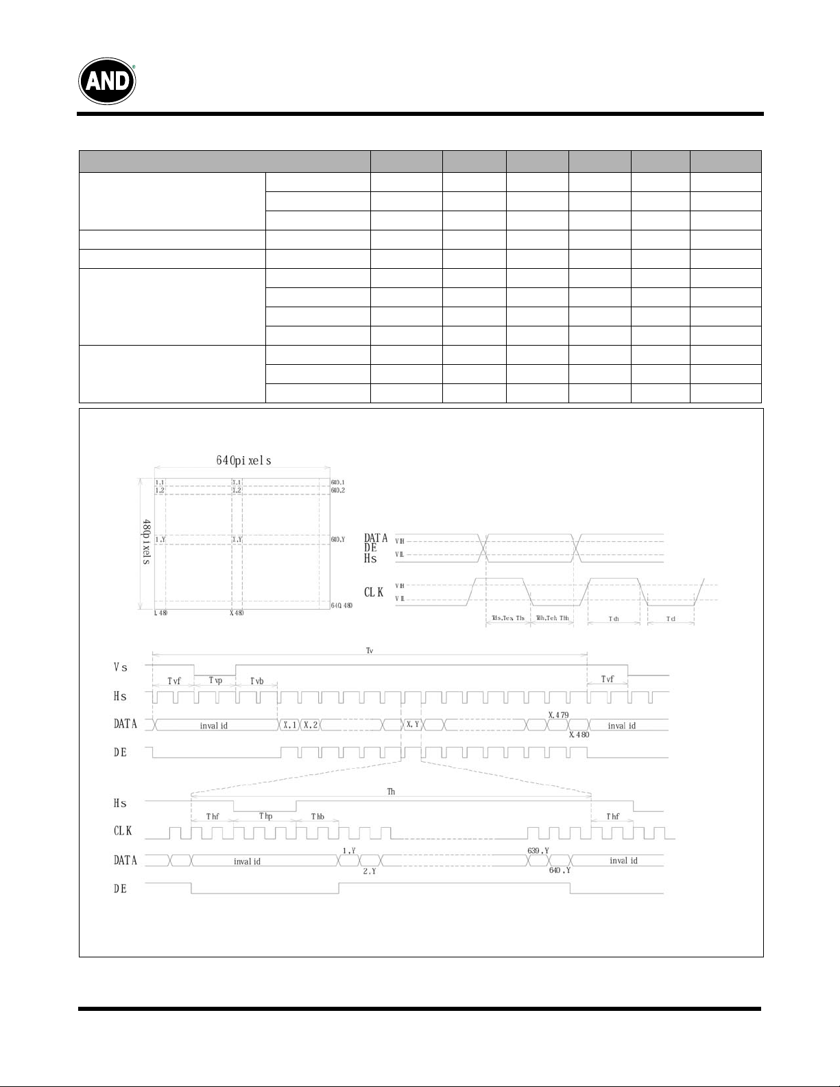
Timing Chart
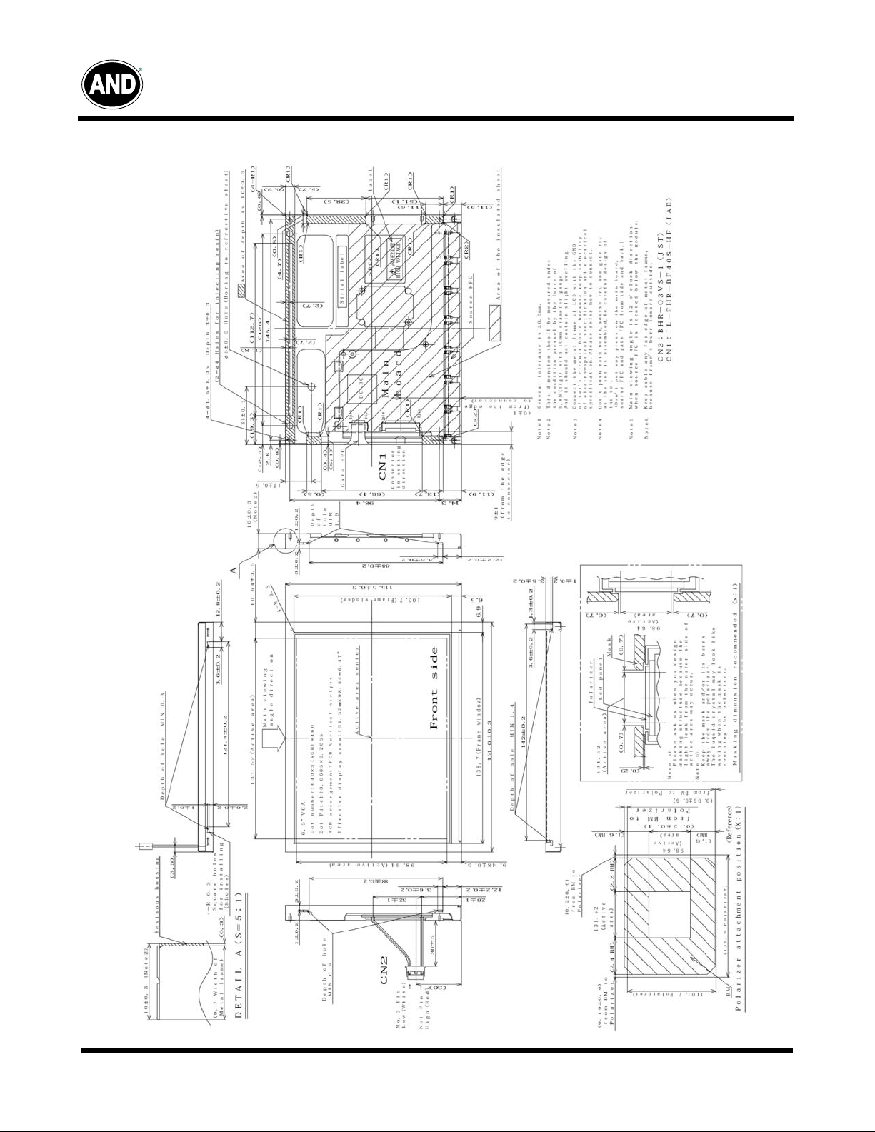
Dimensional Outline
Displays
Timing Specifications
AND065A041F-HB2
Characteristics
Frequency Fck – 25.175 – MHz
CLK Clock
DATA Data Setup/Hold Time Tds/Tdh 5/10 – – ns
DE Data Enable Setup/Hold Time Tes/Teh 5/10 – – ns
Hs Horiz. Sync.
Vs Vert. Sync.
Period Clk – 39.72 – ns
High/Low Time Tch/Tcl 12/12 – – ns
Setup/Hold Time Ths/Thh 5/10 – – ns
Period Th 700 800 832 clk
Pulse Width Thp 4 96 – clk
Front/Back Porch Thf/Thb –/7 13/51 –/– clk
Period Tv 516/16.2 525/16.7 534/17.6 th/ms
Pulse Width Tvp 1 2 – th
Front/Back Porch Thf/Thb –/4 11/32 –/– th
SYMBOL MIN TYP. MAX UNIT REMARKS
Timing Chart
2
Purdy Electronics Corporation • 720 Palomar Avenue • Sunnyvale, CA 94085
Tel: 408.523.8200 • Fax: 408.733.1287 • sales@purdyelectronics.com
www.purdyelectronics.com
1/28/08

Displays
AND065A041F-HB2
640 Pixels
2, 1
2, 2
2, 479
1, 479
2, 480
1, 480
Recommended Inverter: TBD
Block Diagram
1) Drivers are fabricated on the LCD glass
2) Connectors
CN1
1L-FHR-B40S-HF / JAE
Mating connector: FFC (0.5mm pitch)
Photo of back of display
640, 11, 1
640, 21, 2
640, 479
640, 480
480 Lines
Connector Pin Assignments for Interface
CN1; Signal Interface
Terminal No.
1 VDD +3.3V Power Supply
3 VDD +3.3V Power Supply
5
7
9
11
13
15
17
19
21
23
25 G3
27 G1
29 GND Signal Ground
31 R4
33 R2
35 R0
37 GND Signal Ground
39 GND Signal Ground
Symbol Function
2 VDD +3.3V Power Supply
4 VDD +3.3V Power Supply
Signal Ground
GND
6
GSX1
8
DOFF1
10
12
14
16
18 B3
20
22
24
26 G2
28 G0
30 R5
32 R3
34 R1
36 GND Signal Ground
38 CLK Dot Clock
40 GND Signal Ground
Display period compensation signal
Signal Ground
GND
Non-display pd. compensation signal
Signal Ground
GND
Data Enable SIgnal
DE
Signal Ground
GND
Vertical Sync.
VS
Signal Ground
GND
Horizontal Sync.
HS
Signal Ground
GND
B5
B4
Blue Data
B2
B1
B0
Signal Ground
GND
G5
G4
Green Data
Red Data
Note (2): 256K colors are displayed by the combinations of 18 data
bits.
Purdy Electronics Corporation • 720 Palomar Avenue • Sunnyvale, CA 94085
1/28/08 Tel: 408.523.8200 • Fax: 408.733.1287 • sales@purdyelectronics.com
www.purdyelectronics.com
3

Displays
AND065A041F-HB2
Display
BlackLLLLLLLLLLLLLLLLLL –
Green LLLLLLHHHHHHLLLLLL –
Lt. BlueLLLLLLHHHHHHHHHHHH –
Basic
Color
Purple HHHHHHLLLLLLHHHHHH –
YellowHHHHHHHHHHHHLLLLLL –
WhiteHHHHHHHHHHHHHHHHH –
BlackLLLLLLLLLLLLLLLLLL L0
Dark LLLLLHLLLLLLLLLLLL L1
Gray
Scale
of
Red
Light HHHHHLLLLLLLLLLLLL L62
BlackLLLLLLLLLLLLLLLLLL L0
Dark LLLLLLLLLLLHLLLLLL L1
Gray
Scale
of
Green
LightLLLLLLHHHHHLLLLLLL L62
Green LLLLLLHHHHHHLLLLLLGreen L63
BlackLLLLLLLLLLLLLLLLLL L0
Dark LLLLLLLLLLLLLLLLLH L1
Gray
Scale
of
Blue
LightLLLLLLLLLLLLHHHHHL L62
BlackLLLLLLLLLLLLLLLLLL L0
Dark LLLLLHLLLLLHLLLLLH L1
Gray
Scale
of
White
&
Black
Light HHHHHL HHHHHL HHHHHL L62
WhiteHHHHHHHHHHHHHHHHHHWhiteL63
R5 R4 R3 R2 R1 R0 G5 G4 G3 G2 G1 G0 B5 B4 B3 B2 B1 B0
Blue LLLLLLLLLLLLHHHHHH –
Red HHHHHHLLLLLLLLLLLL –
LLLLHLLLLLLLLLLLLL L2
:::
:::
HHHHLHLLLLLLLLLLLL L61
Red HHHHHHLLLLLLLLLLLLGreen L63
LLLLLLLLLLHLLLLLLL L2
:::
:::
LLLLLLHHHHLHLLLLLL L61
LLLLLLLLLLLLLLLLHL L2
:::
:::
LLLLLLLLLLLLHHHHLH L61
Blue LLLLLLLLLLLLHHHHHHBlueL63
LLLLHLLLLLHLLLLLHL L2
:::
:::
HHHHL HHHHHLHHHHHLH L61
Gray Scale
Level
L3~L60
L3~L60
L3~L60
L3~L60
4
Purdy Electronics Corporation • 720 Palomar Avenue • Sunnyvale, CA 94085
Tel: 408.523.8200 • Fax: 408.733.1287 • sales@purdyelectronics.com
1/28/08
www.purdyelectronics.com
Displays
Mechanical Drawing
AND065A041F-HB2
1/28/08 Tel: 408.523.8200 • Fax: 408.733.1287 • sales@purdyelectronics.com
Purdy Electronics Corporation • 720 Palomar Avenue • Sunnyvale, CA 94085
www.purdyelectronics.com
5
 Loading...