

Displays
Features
• VGA (640 x 480 pixels) resolution
• Amorphous silicon TFT LCD panel with LED backlight
• Pixel in stripe configuration
• Light weight and slim
• Displays 262,144 colors
• Optimum Viewing Direction: 6 o’clock
• Image Reversion: Up/Down & Left/Right
• Supports the DENB mode, Sync mode (Hsync+Vsync)
• LVDS transmission interface
• RoHS Compliant
AND050VL-LED-KIT
AND050VL-LED-KIT
640 x 480 Pixels
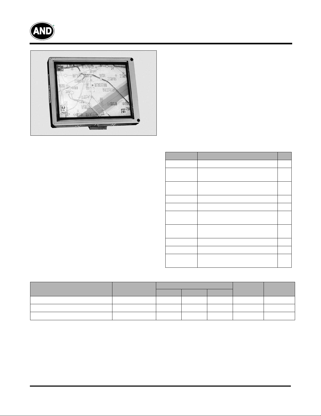
LCD Color Monitor
The AND050VL-LED-KIT is a compact full color TFT LCD
module, whose driving board is capable of converting
composite video signals to the proper interface of LCD panel
and is suitable for computer peripheral, industrial meter,
image communication and multi media.
This device consists of an amorphous silicon panel with
back-light, incorporating a TFT-array that has 640 x 480
pixels on a 5 inch diagonal screen, with pixel in stripe
configuration, 262,144 display colors and a TTL transmission
interface.
Mechanical Characteristics
Parameter Specification Unit
Screen Size 5.0 (diagonal) inch
Display
Format
Display
Colors
Active Area 101.76 (H) x 74.88 (V) mm
Pixel Pitch 0.159 (H) x 0.156 (V) mm
Pixel
Configuration
Outline
Dimension
Weight 173.6 ± 10 g
Back-light 24-LED
Diplay Mode /
Surface
640 (H) x (R, G, B) x 480(V) dot
262,144
Stripe
120.7 (H) x 92.8 (V) x 12.5 (D) mm
Normally white /
Anti-glare & SWV film
Recommended Driving Condition for LED Back Light GND= 0V Ta=25ºC
Specifications
Min. Typ. Max.
– 11.0 11.5 V
– 20 – mA Note 1
– 1.76 1.84 W Note 2
+ V
LED8
* I
LED8
Unit Remark
I
=20mA
L
1
LED2
Symbol
V
LED
I
LED
P
LED
.... + V
LED7
* I
LED7
Parameter
Supply Voltage of LED Backlight
Supply Current of LED Backlight
Backlight Power Consumption
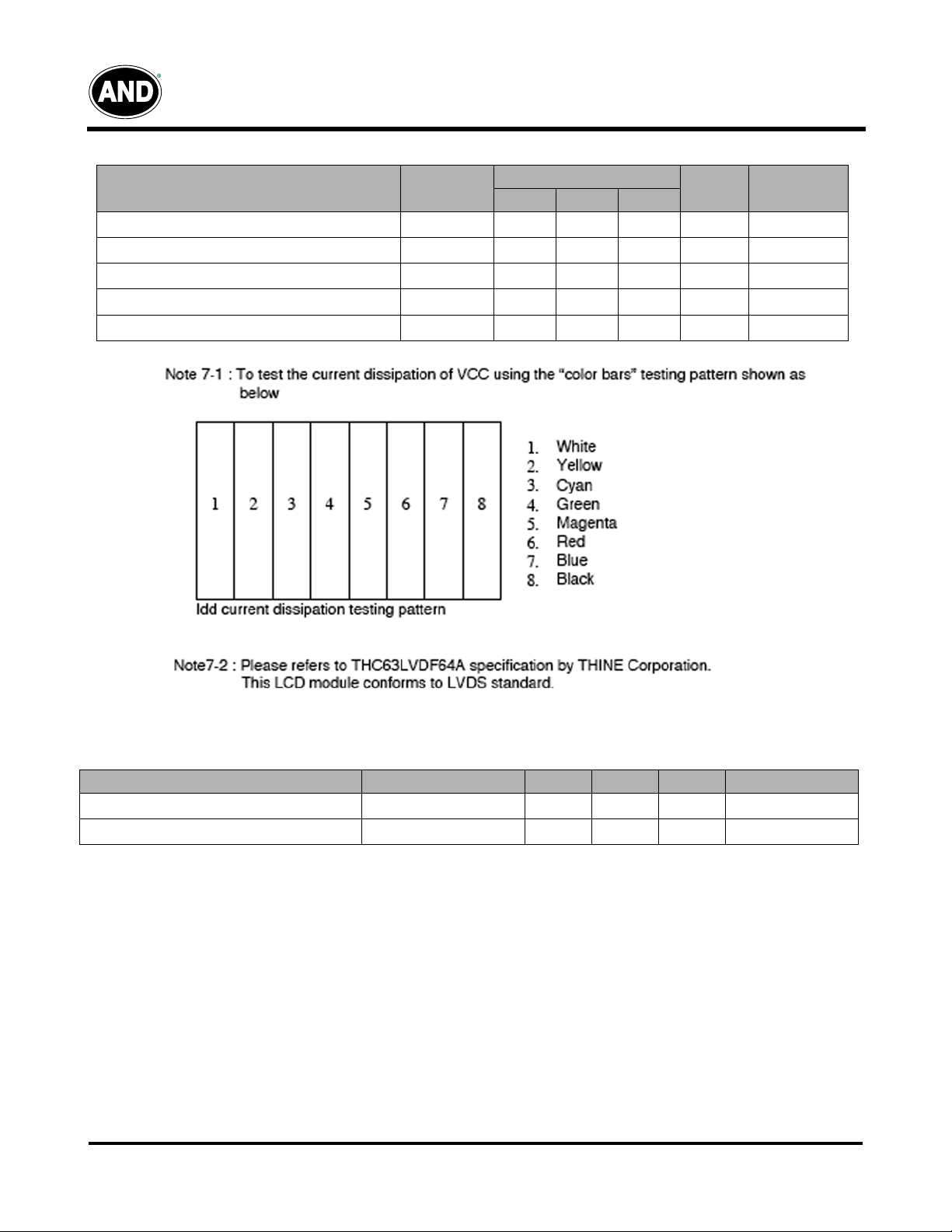
Note 1: The LED driving condition is defined for each LED module. (3 LED Serial)
Note 2: P
Product specifications contained herein may be changed without prior notice. It is therefore advisable to contact Purdy
05/13/03
= V
LED
Tel: 408.523.8200 • Fax: 408.733.1287 • sales@purdyelectronics.com • www.purdyelectronics.com
* I
LED1
Electronics before proceeding with the design of equipment incorporating this product.
+ V
LED1
Purdy Electronics Corporation • 720 Palomar Avenue • Sunnyvale, CA 94085
LED2
* I
*
Displays
Electrical Characteristics: Recommended Operating Conditions GND=0V, Ta=25ºC
Item Symbol
Supply Voltage
Current Dissipation
LVDS Differential Input High Threshold
LVDS Differential Input Low Threshold
V
Voltage V
oom
V
V
V
I
CC
CC
TH
TL
ccm
Specifications
Min. Typ. Max.
3.0 3.3 3.6 V
– 77.90 – mA Note 1
– – 100 mV Note 2
-100 – – Note 2
– 2.7 – V
AND050VL-LED-KIT
Unit Remark
Absolute Maximum Ratings*: GND=OV, Ta=25ºC
Parameters
Supply Voltage
Input Signals Voltage
Symbol Min. Max. Unit Remark
V
CC
V
sig
-0.3 +7.0 V
-0.3
The above are maximum values, which if exceeded, may cause faulty operation or damage to the unit.
Note 1: Input signals include CLK, Hsync, Vsync, DENB, R[0:5], G[0:5] and B[0:5].
05/13/03
Tel: 408.523.8200 • Fax: 408.733.1287 • sales@purdyelectronics.com • www.purdyelectronics.com
Purdy Electronics Corporation • 720 Palomar Avenue • Sunnyvale, CA 94085
V
CC
+0.3
V Note 1
2

Displays
Optical Characteristics Ta = 25ºC
Parameter
Horizontal
Viewing Angle
Contrast Ratio CR
Response Time
Brightness L
Luminance Uniformity U 70 80 – %
LED Life Time +25ºC 20,000 30,000 –
White Chromaticity
Cross Talk
LVDS Interface Block Diagram
Vertical
Rise Tr
Fall Tf – 25 50
Symbol Conditions
θ
= 21, 22
10
θ
= 12 30 40 –
θ
= 11 50 55 –
x
y 0.31 0.34 0.37
CR >
at optimized
viewing angle
θ
= 0º
θ
=
0º 400 450 – cd/m2
θ
=0º
θ
=0º – – 3.5 %
Specifications
Min. Typ. Max.
±55 ±60
200 400 – –
–1530
0.28 0.31 0.34
AND050VL-LED-KIT
Unit
deg
ms
hr
–
05/13/03
Tel: 408.523.8200 • Fax: 408.733.1287 • sales@purdyelectronics.com • www.purdyelectronics.com
Purdy Electronics Corporation • 720 Palomar Avenue • Sunnyvale, CA 94085
3

Displays
Input Terminals:
TFT-LCD Panel Driving
Connector Type: DFL19K-20P-1H(HRS)
Pin #. Symbol Function
1 Vcc +3.3V Power Supply
2 Vcc +3.3V Power Supply
3 GND Ground
4 GND Ground
5 IN0- LVDS receiver signal channel 0
6 IN0+ LVDS receiver signal channel 0
7 GND Ground
8 IN1- LVDS receiver signal channel 1
9 IN1+ LVDS receiver signal channel 1
10 GND Ground
11 IN2- LVDS receiver signal channel 2
12 IN2+ LVDS receiver signal channel 2
13 GND Ground
14 CLK- LVDS receiver signal clock
15 CLK+ LVDS receiver signal clock
16 GND Ground
17 NC No Connection
18 NC No Connection
19 GND Ground
20 GND Ground
AND050VL-LED-KIT
Backlight Driving
Connector Type: JST BHSR-02VS-1, Pin No 2-pin
Pin No.
1 + Input terminal (Positive electrode side) Wire color: Red
2 - Input terminal (Ground side) Wire color: Black
Symbol Description Remarks
05/13/03
Tel: 408.523.8200 • Fax: 408.733.1287 • sales@purdyelectronics.com • www.purdyelectronics.com
Purdy Electronics Corporation • 720 Palomar Avenue • Sunnyvale, CA 94085
4
Displays
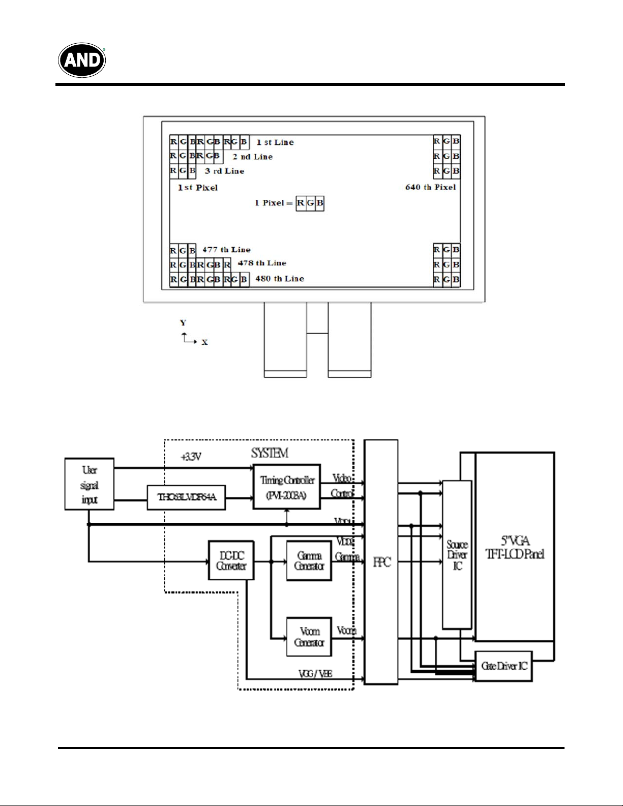
Pixel Arrangement - The LCD module pixel arrangement is stripe.
AND050VL-LED-KIT
Block Diagram - TFT-module Block Diagram.
05/13/03
Tel: 408.523.8200 • Fax: 408.733.1287 • sales@purdyelectronics.com • www.purdyelectronics.com
Purdy Electronics Corporation • 720 Palomar Avenue • Sunnyvale, CA 94085
5
–
Displays
Interface Timing: Timing Parameters
Item
Power Supply VCC 3.0 3.3 3.6 V
CLK Frequency
Period Hp
Display period Hdp – 640 – tc
Pulse width Hpw – 96 – tc
HSYNC
VSYNC
DENB
R, G, B
Back-porch Hbp – 46 – tc
Front-porch Hfp – 18 – tc
Hpw+Hbp – – 142 – tc
Hsync-CLK Hhc 10 – Tc-10 ns
Vsync-Hsync Hvh 0 0 200 tc
Period Vp
Display period Vdp – 480 – Hp
Pulse width Vpw – 2 – Hp
Back-porch Vbp – 33 – Hp
Front-porch Vfp – 10 – Hp
Vpw + Vbp – – 35 – Hp
Horizontal scanning period T1 – 800 – tc
Horizontal display period T2 – 640 – tc
Vertical display period T3 – 480 – T1
Frame cycling period T4 520 525 800 T1
CLK-DATA Dcd 10 – – ns
DATA-CLK Ddc 8 – – ns
AND050VL-LED-KIT
Symbol Min. Typ. Max. Unit
1/tc – 25 – MHz
tc –40–ns
–32–us
– 800 – tc
– 16.8 – ms
– 525 – Hp
05/13/03
Tel: 408.523.8200 • Fax: 408.733.1287 • sales@purdyelectronics.com • www.purdyelectronics.com
Purdy Electronics Corporation • 720 Palomar Avenue • Sunnyvale, CA 94085
6
Displays
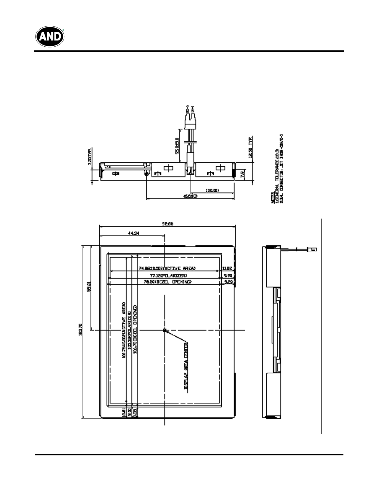
Mechanical Drawing of TFT-LCD Module
Outline Drawing : Front View (unit mm)
AND050VL-LED-KIT
05/13/03
Tel: 408.523.8200 • Fax: 408.733.1287 • sales@purdyelectronics.com • www.purdyelectronics.com
Purdy Electronics Corporation • 720 Palomar Avenue • Sunnyvale, CA 94085
7
Displays
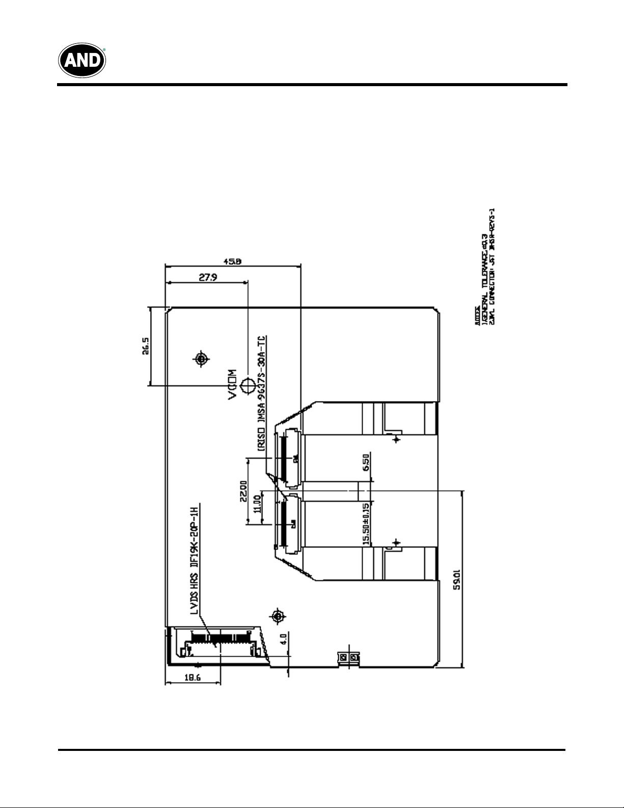
Ouline drawing : Rear View (unit mm)
AND050VL-LED-KIT
05/13/03
Tel: 408.523.8200 • Fax: 408.733.1287 • sales@purdyelectronics.com • www.purdyelectronics.com
Purdy Electronics Corporation • 720 Palomar Avenue • Sunnyvale, CA 94085
8

Displays
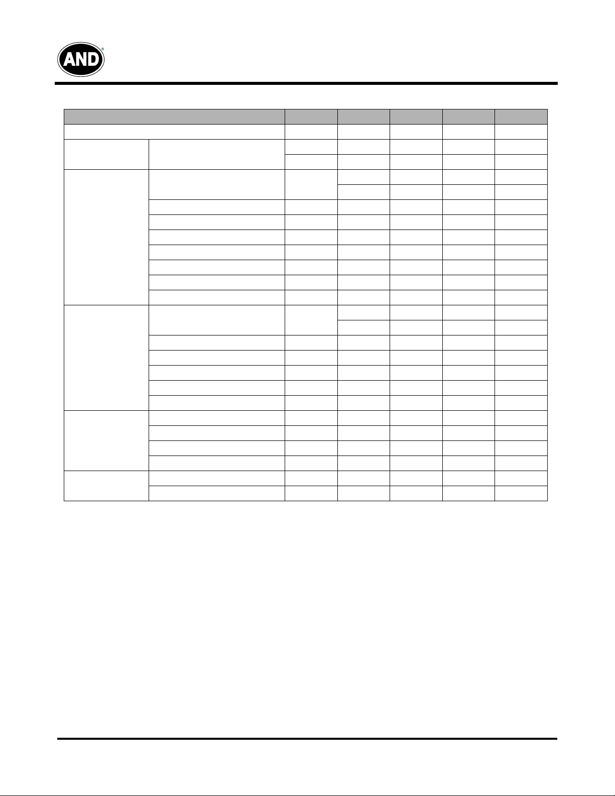
Display Color and Gray Scale Reference
Basic
Color
Gray
Scale
of
Red
Gray
Scale
of
Green
Gray
Scale
of
Blue
Color
R5 R4 R3 R2 R1 R0 G5 G4 G3 G2 G1 G0 B5 B4 B3 B2 B1 B0
Black 000000000000000000
Red (63) 111111000000000000
Green (63) 000000111111000000
Blue (63) 000000000000111111
Cyan 000000111111111111
Magenta 111111000000111111
Yellow 111111111111000000
White 111111111111111111
Red (00) 000000000000000000
Dark 000001000000000000
000010000000000000
111101000000000000
Light 111110000000000000
Red (63) 111111000000000000
Green (00) 000000000000000000
Dark 000000000001000000
000000000010000000
000000111101000000
Light 000000111110000000
Green 000000111111000000
Blue (00) 000000000000000000
Dark 000000000000000001
000000000000000010
000000000000111101
Light 000000000000 111110
Blue (63) 000000000000111111
Red Green Blue
:::
:::
:::
:::
:::
:::
AND050VL-LED-KIT
Input Color Data
05/13/03
Tel: 408.523.8200 • Fax: 408.733.1287 • sales@purdyelectronics.com • www.purdyelectronics.com
Purdy Electronics Corporation • 720 Palomar Avenue • Sunnyvale, CA 94085
9

φ
Displays
PC-TFT-050VL
Interface Board
Features
• Used for TFT-LCD display: 5” AND050VL-LED
• Input Signal: D-SUB VGA signal, composite video
channels and S-Video
• Auto detect input signal when power is on
• Operating Temperature: 0ºC ~ 60ºC
• Storage Temperature: -20ºC ~ 80ºC
• RoHS Compliant
Mechanical Characteristics for Board
Item Specification Unit
Outline Dimension 113 (W) x 68(H) x 15.7 (D) mm
Top Layer Height (max) 12 mm
Board thickness 1.2 mm
Four Screw Holes
Absolute Maximum Rating
Item
Operating Temperature Top – 0 60 °C
Storage Temperature Tstg – -20 80 °C
Symbol Conditions Min. Max. Unit
AND050VL-LED-KIT
The PC-TFT-050VL is designed to work
with the AND050VL-LED color TFT display
which is suitable for security, video game,
door phone, video phone, portable TV and
instrument display applications..
2.5 mm
Input/Output Terminals - CON6
LVDS Connector: MOLEX 87758-32 or compatible
Pin No.
Input/Output Terminals - CON3
VGA Connector: JST B12B-PH-K-S or compatible
Pin No.
Symbol Pin No. Symbol Pin No. Symbol Pin No. Symbol Pin No. Symbol
1 DA0- 8 CLK1- 15 DA5- 22 DA7- 29 VCC
2 DA0+ 9 CLK1+ 16 DA5+ 23 DA7+ 30 VCC
3 DA1- 10 DA3- 17 GND 24 GND 31 VCC
4 DA1+ 11 DA3+ 18 DA6- 25 GND 32 VCC
5 DA2- 12 DA4- 19 DA6+ 26 GND
6 DA2+ 13 DA4+ 20 CLK2- 27 GND
7 GND 14 GND 21 CLK2+ 28 VCC
Input/Output Terminals - CON11
Keyboard Operation Port: MOLEX 53261-1071 or compatible
Symbol Pin No. Symbol
1R+ 9
2 G+ 10 GND
3B+ 11NC
4 NC 12 SDA-VGA
5 VGA-DET 13 IN-HS
6 GND 14 IN-VS
7 GND 15 SCL-VGA
8 GND
VGA-
POWER
Pin No.
1 Auto 6 +3.3V
2 Right 7 GND
3 Left 8 Remote
4 Menu 9 LED-Green
5 Power 10 LED-Red
Input/Output Terminals - CON1
Power Connector: JST B2B-XH-A or compatible
Pin No.
1 GND 2 +12V
Symbol Pin No. Symbol
Symbol Pin No. Symbol
05/13/03
Tel: 408.523.8200 • Fax: 408.733.1287 • sales@purdyelectronics.com • www.purdyelectronics.com
Purdy Electronics Corporation • 720 Palomar Avenue • Sunnyvale, CA 94085
10
Displays
Electrical
Symbol
Vin
Iin
Pin
Input/Output Terminals - CON7
TTL Connector: MOLEX 87758-30 or compatible
Pin No.
1 CLK 7 R2 13 G1 19 E0 25 GND
2 HS 8 R3 14 G2 20 B1 26 DEN
3 VS 9 R4 15 G3 21 B2 27 VCC
4 GND 10 R5 16 G4 22 B3 28 VCC
5 R0 11 GND 17 G5 23 B4 29 L/R
6 R1 12 G0 18 GND 24 B5 30 U/D
Input/Output Terminals - CON2
Audio In Connector:JST B4B-XH-A
or compatible
Pin No.
1 GND 3 GND
2 L-IN 4 R-IN
DC (+V)
DC (+12V)
Symbol Pin No. Symbol Pin No. Symbol Pin No. Symbol Pin No. Symbol
Symbol Pin No. Symbol
Conditions Input/Output Min. Ty p. Max. Unit
12 12 15 V
Input
Input/Output Terminals - CON8
Video & S-Video Connector: JST-B5B-PH-K-S or compatible
Pin No. Symbol Pin No. Symbol
1GND 4 Y
2 Video 5 C
3GND
– TBD – mA
– TBD – W
AND050VL-LED-KIT
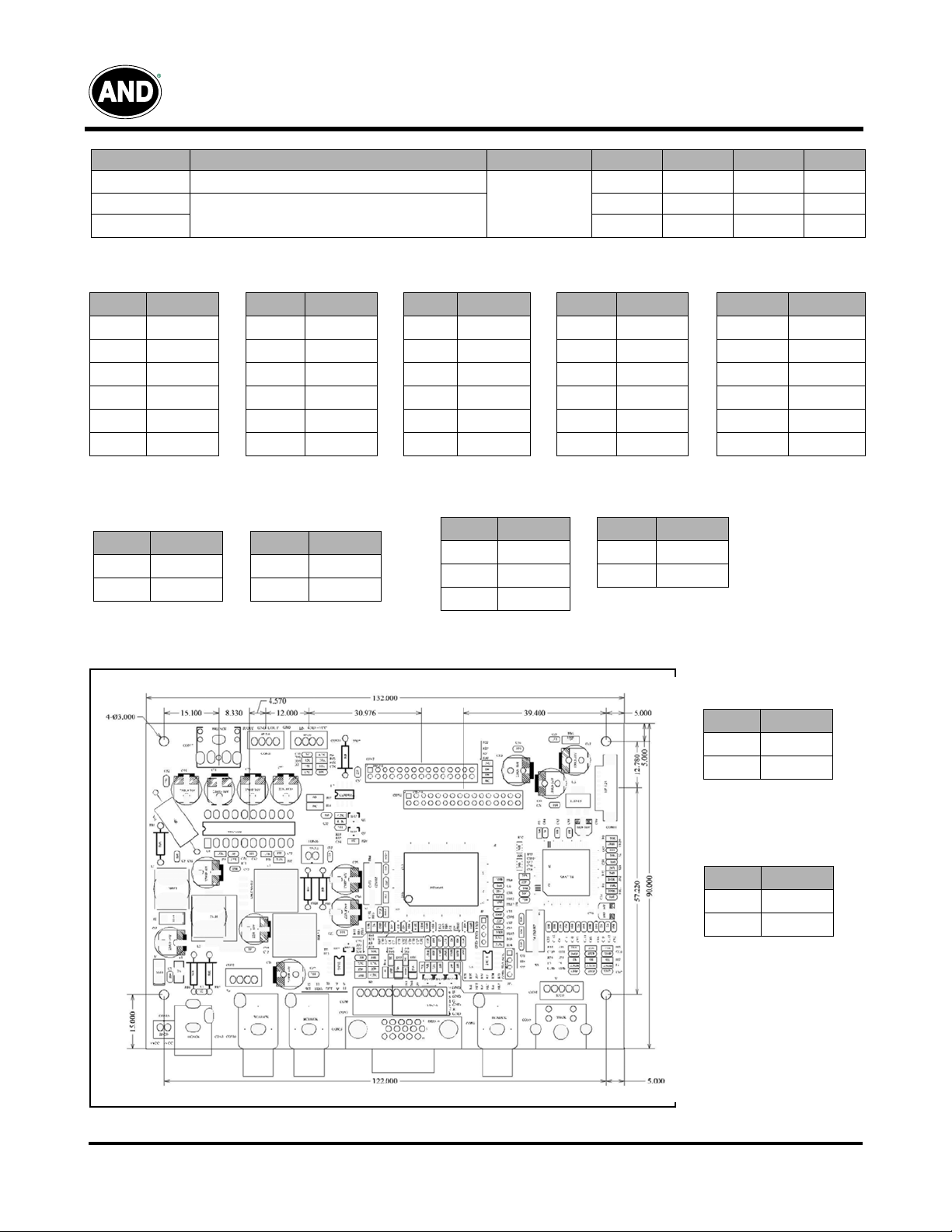
Driver Board Outline Drawing
Input/Output Terminals
- CON13
Audio In Connector
Pin No. Symbol
1 R-IN
2 GND
Input/Output Terminals
- CON10
Audio In Connector
Pin No. Symbol
1 L-IN
2GND
05/13/03
Tel: 408.523.8200 • Fax: 408.733.1287 • sales@purdyelectronics.com • www.purdyelectronics.com
Purdy Electronics Corporation • 720 Palomar Avenue • Sunnyvale, CA 94085
11

Driver Board
Displays
AND050VL-LED-KIT
Driver Board Introduction
Port Definition Port Definition
CON7 Connect port of driver board with LCD Connector (TTL) CON8 Composite video or S-video input port
CON6 Connect port of driver board with LCD Connector (LVDS) CON5 S-video input port
CON3 Analog VGA signal input port (15 pin) CON4 Composite video input port
CON9 Analog VGA signal input port (12 pin) CON10 Connection port of audio in
CON11 Keyboard operation port CON13 Connection port of audio in
CON1 Power input port (DC +12V) CON2 Connection port of audio in
05/13/03
Tel: 408.523.8200 • Fax: 408.733.1287 • sales@purdyelectronics.com • www.purdyelectronics.com
Purdy Electronics Corporation • 720 Palomar Avenue • Sunnyvale, CA 94085
12
 Loading...