

Page 1
Page 2

table of contents
table of contents
Chapter one • Introduction .......................................... 1
About this Guide ....................................................................... 2
System Specifications ................................................................ 2
Installing Punch! Super Home Suite............................................. 3
Installing Punch! Super Home Suite 3D Viewers............................. 3
Registering Your Copy of Punch! Super Home Suite........................ 4
Punch! Technical Support ........................................................... 4
Important System Settings ......................................................... 4
Speed Tips ................................................................................ 5
Program Tips............................................................................. 5
Chapter two • Tutorial.................................................. 7
Start with Your Lot Size and Shape.............................................. 8
Draw the Exterior Walls .............................................................. 9
Draw the Interior Walls............................................................... 9
Doors & Openings .................................................................... 10
Windows................................................................................. 11
Add a Second Floor .................................................................. 12
Drawing Stairs......................................................................... 13
Add a Railing .......................................................................... 13
Add a Roof.............................................................................. 14
Draw a Sidewalk ...................................................................... 15
Put in a Flowerbed and Edge it .................................................. 16
Fence the Backyard .................................................................. 17
Add a Deck ............................................................................. 17
Add Colors and Textures ........................................................... 18
Add Objects ............................................................................ 20
Page 3

Punch! Super Home Suite User’s Guide
Chapter three • Program Tools .................................... 21
Pointer Tool ............................................................................ 22
Rotate Tool ............................................................................. 22
Dimension Tool........................................................................ 22
Text Tool ................................................................................ 23
Pan Tool ................................................................................. 23
Zoom Tool ............................................................................... 23
Viewpoint Tool ........................................................................ 23
Virtual Ruler ........................................................................... 24
Associative Dimensioning ......................................................... 24
Chapter four • Drawing Tools ..................................... 25
Wall Tool ................................................................................ 26
Door Tool................................................................................ 28
Window Tool ........................................................................... 30
Roof Tool ................................................................................ 32
Stairs Tool .............................................................................. 34
Railing Tool ............................................................................ 37
Flooring/Ground Covering Tool .................................................. 38
Pathway Tool .......................................................................... 40
Fill Region Tool ....................................................................... 42
Edging Tool ............................................................................. 43
Fence Tool .............................................................................. 44
Gate Tool ................................................................................ 46
Topography Tool ...................................................................... 48
CAD Tool ................................................................................ 49
Deck Tool ............................................................................... 50
Landscaping Tool ..................................................................... 52
Objects Tool ............................................................................ 54
ii
Page 4

Table of Contents
Chapter five • Menu Bars ........................................... 55
The File Menu ......................................................................... 56
The Edit Menu ......................................................................... 57
The Design Menu ..................................................................... 59
The Options Menu.................................................................... 61
The View Menu ........................................................................ 63
The Window Menu ................................................................... 65
The Help Menu ........................................................................ 65
Chapter six • LiveView™ Environment ........................ 67
Walk-Through Tool ................................................................... 68
Fly-Around Tool ...................................................................... 68
Applying Textures & Colors ....................................................... 69
Lighting & Shadows ................................................................. 71
Viewing Speed......................................................................... 73
Camera Angle .......................................................................... 73
Viewpoint Direction Arrows....................................................... 74
Punch! LiveView Size Options.................................................... 75
Chapter seven • Floorplan Trace & AutoFraming .......... 77
Matching the Drawing Scale ...................................................... 78
Tips for Using FloorPlan Trace ................................................... 79
AutoFraming ........................................................................... 80
Chapter eight • Home Estimator ................................. 81
Introducing Home Estimator ..................................................... 82
Using Home Estimator .............................................................. 82
Construction Square Footage Cost .............................................. 83
Window Schedule .................................................................... 83
Door Schedule ......................................................................... 84
Framing Stud Schedule............................................................. 84
Window/Door Header Schedule.................................................. 84
Roofing Cost ........................................................................... 84
Roof Truss Schedule ................................................................. 84
Landscape Lot Cost .................................................................. 84
Landscape Plant Schedule......................................................... 84
iii
Page 5

Punch! Super Home Suite User’s Guide
Chapter nine • RealModel®......................................... 85
RealModel Introduction ............................................................ 86
Choosing a Scale and Construction Material for Your Real Model .... 86
Optimizing Your Printer Settings for RealModel ........................... 87
Floor Templates ....................................................................... 88
Wall Templates ........................................................................ 89
Roof Templates ........................................................................ 90
Texture Templates.................................................................... 91
Applying the Texture to the Model............................................. 92
Building Your RealModel® - Review ............................................ 93
Chapter ten • 3D Furniture Workshop ......................... 95
3D Furniture Workshop™ Introduction ....................................... 96
Drawing Tools Overview ............................................................ 96
Customizing Tools Overview ...................................................... 98
Drawing Grid Overview ............................................................. 99
Program Tools Overview ...........................................................100
The File Menu ........................................................................102
The Edit Menu ........................................................................103
The Design Menu ....................................................................106
The Options Menu...................................................................108
The View Menu .......................................................................109
The Help Menu .......................................................................110
Creating Custom 3D Objects......................................................111
Opening & Editing Objects .......................................................113
iv
Index....................................................................... 115
Page 6

Chapter one
Chapter one
INTRODUCTION
Contents
About this Guide 2
System Specifications 2
Installing Punch! Super Home Suite 3
Installing Punch! 3D Viewers 3
Registering Your software 4
Punch! Technical Support 4
Important System Settings 4
Speed Tips 5
Program Tips 5
Page 7

Punch! Super Home Suite User’s Guide
About this Guide
This User’s Manual is designed to familiarize you with Punch! Super Home
Suite’s various programs, tools, and their uses. You will need to be
comfortable with the Windows environment and understand the following
terms:
• Click - Press and release the left button on the mouse.
• Right-Click - Press and release the right button on the mouse.
• Double-Click - Press and release the left button on the mouse twice
• Click & Drag - Press the left mouse button and hold it down while moving
the mouse.
• Drag & Drop - Selecting an item or some text and then moving it to a
new location.
• Release - Taking your finger off the mouse button.
• Scrolling - Scroll bars are located at the right and bottom of the window.
You can reposition the floorplan by clicking on the arrows at the ends of
each scroll bar.
If these terms and techniques are unfamiliar to you, please take some time
to become acquainted with them before continuing.
2
System Specifications
Recommended Minimum
• Pentium Processor • 486-DX Processor
• Windows®95, 98 or Higher • Windows®95 or Higher
• 16 MB of RAM • 8 MB of RAM
• 175 MB of Hard Disk Space • 175 MB of Hard Disk Space
before installation before installation
• 100 MB of usable Hard Disk Space • 100 MB of usable Hard Disk Space
after installation after installation
• VGA Video Card set at 800x600 • VGA Video Card set at 800x600
Resolution & 16 bit Color Depth Resolution & 16 bit Color Depth
• CD-ROM • CD-ROM
• Mouse or other pointing Device • Mouse or other pointing Device
Page 8

Installing Punch! Super Home Suite
1. A fragmented hard drive is a common cause of installation errors when
installing new software. We recommend that you defragment your hard
drive before beginning installation.
2. Place the Punch! Super Home Suite CD-ROM in the CD-ROM drive of
your computer.
3. Run “Windows Explorer” from the “Start” menu and Double-Click the
“SuperSetup.exe” program from the directory window for your CD-ROM
drive.
4. Follow the installation instructions on your screen to install Punch!
Super Home Suite.
5. When the program installation is almost complete, you will be asked if
you wish to install Adobe® Acrobat Reader. This program will need to be
installed if you wish to view the on-line PDF User’s Guide.
6. If you have Internet access, please follow the link to the URL to register
your software online. If not, please call 1-800-365-4832 to register.
Chapter 1: Introduction
7. The installer will automatically place a short-cut to Punch! Super Home
Suite inside the “Start” menu.
Installing Punch! Super Home Suite 3D Viewers
1. Place the Punch! Super Home Suite CD-ROM in the CD-ROM drive of
your computer.
2. Run “Windows Explorer” from the “Start” menu. Inside the folder named
“Viewers” you will find five subfolders. Open the folder named “Viewer1”
and Double-Click the “Viewer1.EXE” program.
3. Follow the installation instructions on your screen.
4. The installer will automatically place a short-cut to Punch! Super Home
Suite 3D Viewer inside the “Start” menu.
3
Page 9

Punch! Super Home Suite User’s Guide
Registering Your Copy of Punch! Super Home Suite
It is important that you register your copy of Punch! Super Home Suite.
Software registration allows you to obtain technical support and enables us to
notify you of software updates. Registration is quick and easy; simply call our
toll-free number (please have your Punch! Super Home Suite serial number
available when you call). The serial number is located on the back of the jewel
case.
If you chose not to register your software during the installation process,
you may register it on-line at any time by visiting to www.punchsoftware.com
Punch! Technical Support
Technical support is available by email at “techsupport@punchsoftware.com”
and by phone, free for 60 days from the date of purchase, $10 per call
NOTE:
Your serial
number is
located on the
back of the CD
jewel case.
thereafter at 1-800-365-4832. You must have your Punch! Super Home Suite
registered serial number available when you call.
Important System Settings
1. Set your Display Settings to 800x600 pixels and High Color (16 Bit). Go
to your “Start” menu, select Settings>Control Panel>Display>Settings.
Punch! Software
toll-free registration:
1-800-365-4832
4
2. If you notice that the 3D display is not clear, set back the Graphics
Acceleration. Go to your “Start” menu, select Settings>Control Panels>
System>Performance>Graphics, then set the acceleration back one
notch.
3. By default, all Punch! Super Home Suite measurements display in
Inches, to choose Centimeters go to Design>Unit of Measure..., select
Metric.
Page 10

Chapter 1: Introduction
Speed Tips
You can “Speed Up” the program by changing some of the program’s default
settings.
1. Close the LiveView window when you are not working in 3D. No 3D
calculations are performed when the LiveView window is closed.
2. Choose the Quarter-View window size for LiveView instead of Full-View
to increase 3D rendering speed. 3D rendering speed increases as the
LiveView window becomes smaller in size.
3. Set your Display Screen Settings to 16-bit, 65,000 colors for optimum
3D rendering speed.
4. You don’t have to wait for a 3D view to render every time. Just click the
mouse in the LiveView window to interrupt rendering.
5. Hide the floors that are not being drawn. By turning off the inactive
floors, the program will not waste resources on them.
Program Tips
1. To diagram HVAC, plumbing and electrical, use the CAD Tool. It allows
geometry to be placed on the 2D floorplan without appearing in 3D.
2. To design a home with a basement, simply use the first floor as the
basement level and the second floor as the main floor. To show this in
LiveView, use the Topography Tool to raise the level of the ground
around the home.
3. If you wish to render shadows from a specific direction, change the light
source. From the View menu, choose “3D Lighting,” select the direction
from which you would like the lighting to appear. Make sure you turn
on the 3D Shadow option, also found under the View menu. The
LiveView window also includes Lighting & Shadow icons.
4. To signify an oddly-shaped lot, use the CAD Tool to draw your exact lot
shape. While it will not show in the 3D RealView window, it will print on
all 2D plans.
5
Page 11

Chapter two
Chapter two
Contents
Start with your lot size and shape 8
Draw the exterior walls 9
Draw the interior walls 9
Doors & Openings 10
Windows 11
Add a Second Floor 12
Drawing Stairs 13
TUTORIAL
Add a Railing 14
Add a Roof 14
Draw a Sidewalk 15
Put in a Flowerbed and edge it 16
Add a deck 17
Fence the backyard 17
Add Colors and Textures 18
Add Objects 20
Page 12
Punch! Super Home Suite User’s Guide
The Basics
This chapter contains a Quick Start Exercise which covers the basics of
Punch! Super Home Suite. In the course of this exercise you will create a
simple design and learn the function of each tool.
Once you understand the basic concepts that we will cover in this chapter
you will be able to design the home of your dreams!
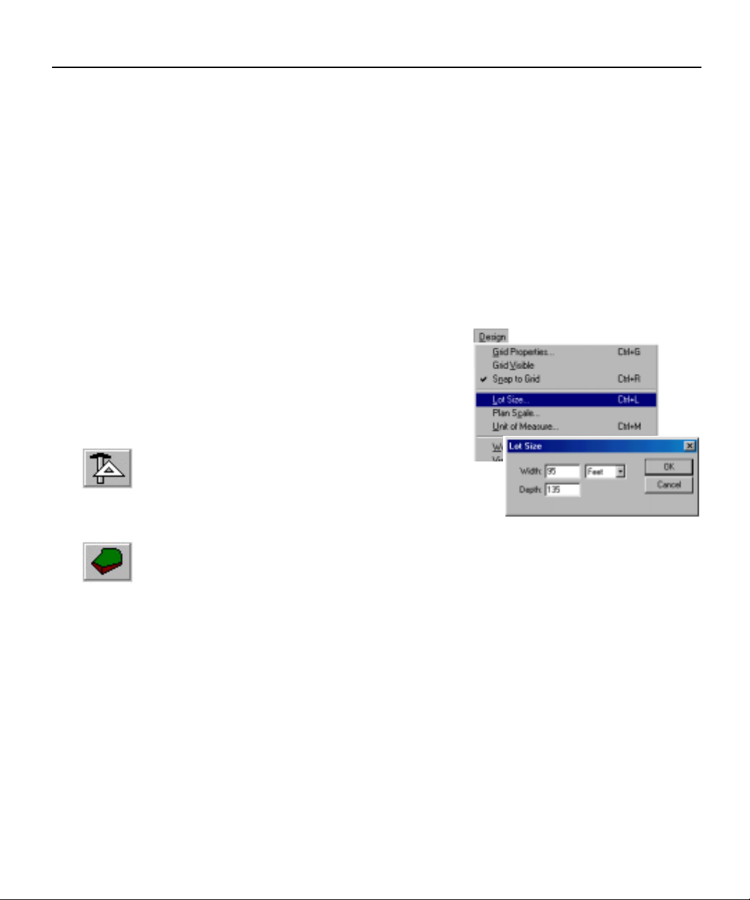
Start with your lot size and shape
First enter the dimensions of your lot.
The basic shape of your lot will appear in the
window.
Although it isn’t necessary for this
tutorial, if you have an irregular lot like a cul
de sac, select the CAD Tool and use the
shapes in the preview bar to outline your lot’s
shape. If your lot has any distinguishing features,
i.e. trees, slope, etc., you will want to indicate
them at this time, too. To define a sloping lot you will need to use the Topo
Tool. To create a straighter edge (like around a foundation) use more layers to
build up the grade.
For more information on the CAD and Topo Tools, see Chapter 4.
8
Page 13
Chapter 2: Tutorial
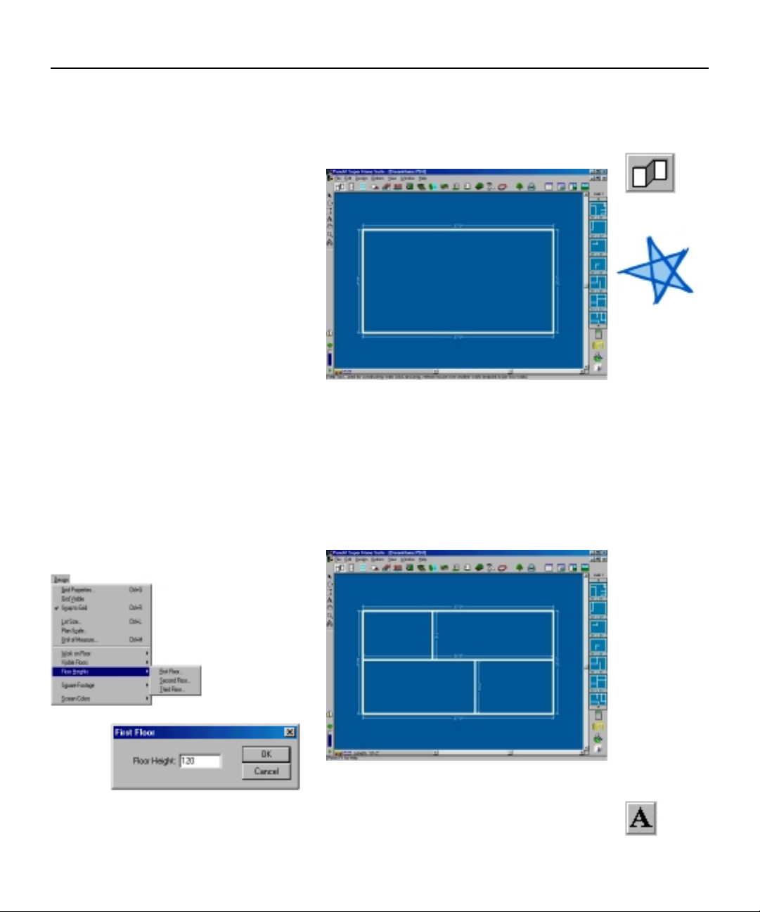
Draw the exterior walls
After defining your lot, the next step will be to draw the outside perimeter
of your floorplan.
Select the Wall Tool and draw a
37’0” x 20’0” rectangle.
Draw the interior walls
Once you’ve defined the outer edge of your floorplan, you can begin
drawing interior walls. Select the Wall Tool again and divide the floorplan into
two rooms.
Now, let’s change the ceiling height for the entire first floor. Select Floor
Heights under Design menu. Floor Heights are measured in inches. You may
also change individual wall heights by Right-clicking on the wall and selecting
Custom Wall Segment.
Note:
The perimeter
must be intact
for Punch!
Super Home
Suite to
accurately
calculate square
feet.
When you view
your design in
RealView and
you notice
“grass” growing
inside your
floorplan or you
have “carpet”
spilling outside,
there are walls
which will need
to be joined.
As you’re drawing walls and rooms, you will want to label them. Select the
Text Tool, type the room name and position it where desired.
9
Page 14
Punch! Super Home Suite User’s Guide
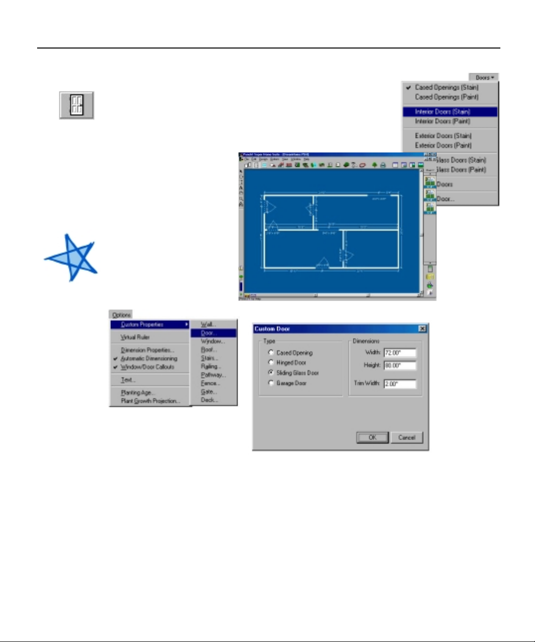
Doors & Openings
Select the Door Tool and then choose from the styles
in the drop down menu. Place an Interior Door between
the two rooms and an Exterior Door on an outside wall.
You can change the style of any door at any time
through the Door
Options menu. This
menu is available under
the Options menubar,
the Doors drop down
menu and by Rightclicking the door in the
plan window.
Note:
When placing
hinged doors,
the first click
places the
door and a
second mouse
click sets the
direction and
angle of the
door.
10
Page 15
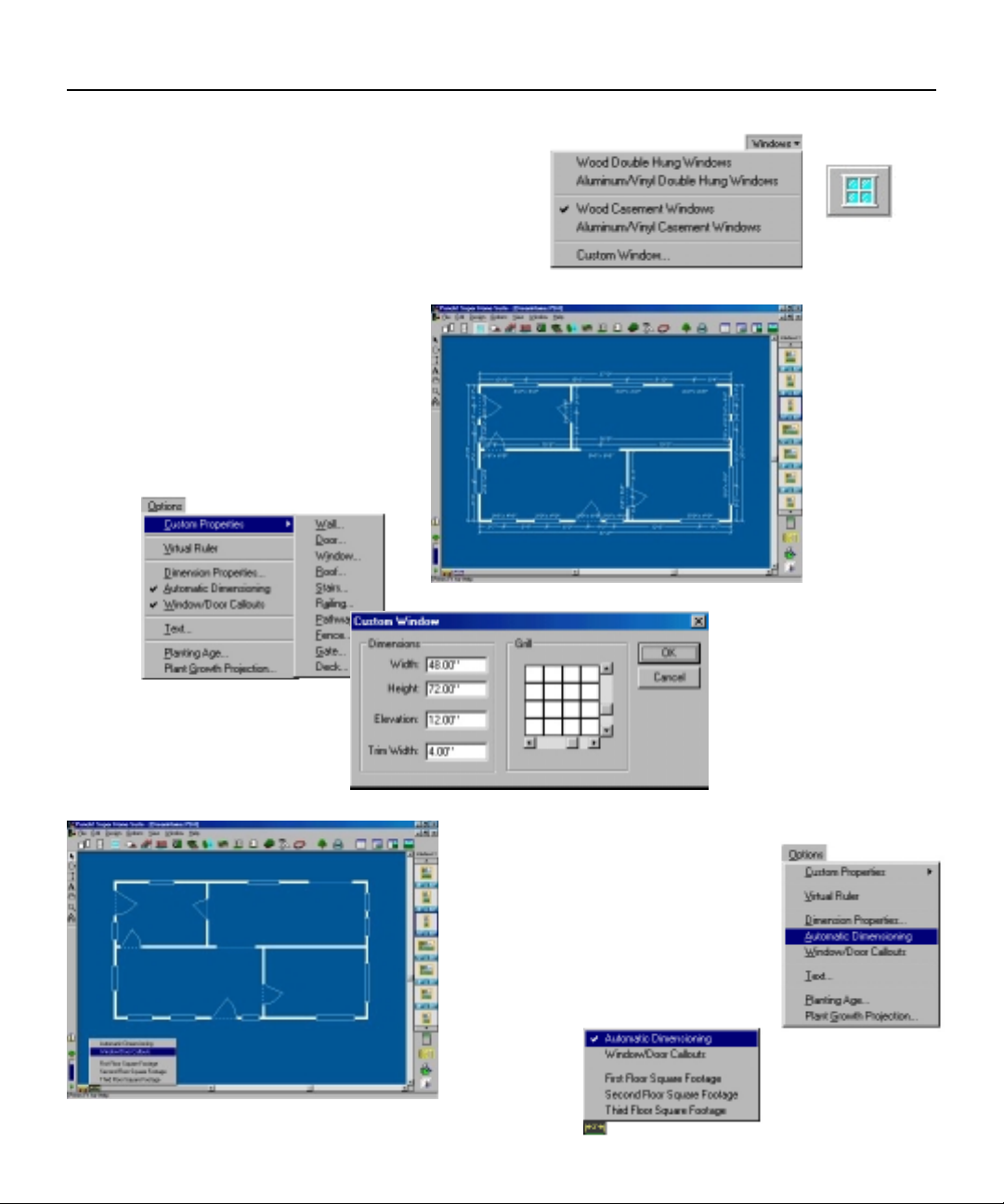
Windows
Select the Window Tool and Drag & Drop a few
into your design. It is not critical to match the
exact placement in these examples.
As with Doors, and many of the other tools,
you can change the style of any
window at any time by calling the
Window Options menu. This menu is
available under the Options menubar,
the Window drop down menu and by
Right-clicking the window in the plan
window.
Chapter 2: Tutorial
If you want to view your
floorplan without the
dimensions, deselect Automatic
Dimensioning and Window/
Door Callouts under the Options
menu or choose from the
Associative Dimension icon at
the bottom
of your
window.
11
Page 16
Punch! Super Home Suite User’s Guide
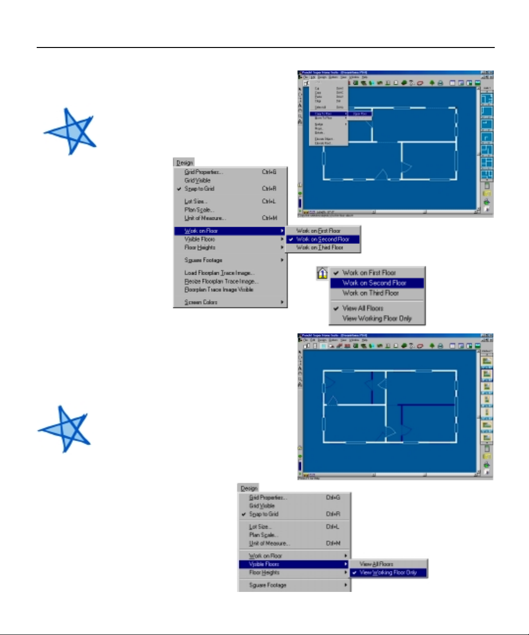
Add a Second Floor
Create a Second Floor that is the
same size as the First Floor. Select an
outside wall, then select Copy to
Floor> Upper Floor from the Edit
Note:
Punch! Super
Home Suite
makes it easy
to tell at a
glance on
which floor
you are
working.
Each floor is
assigned a
separate color.
In addition,
you can
customize
your screen
color scheme.
This option is
located under
the Design
Menu.
Tip:
If you wish,
you may use
the Edit>
Select All
command to
copy all Walls,
Doors and
Windows to the
Second Floor.
menu.
NOTE:
This step
copies all
four outside
walls and all
Doors and
Windows
contained
on these
walls, delete
the Doors
and
Windows you do not wish to retain.
Select Work on Floor>Work on
Second Floor from the Design menu
to make the Second Floor active.
Follow the previous steps to add
Interior Walls, Doors and Windows to
the Second Floor.
At times you may want to view
only the floor that you are designing;
this option is available from both the
Design menubar or the View Floor
icon.
12
Page 17
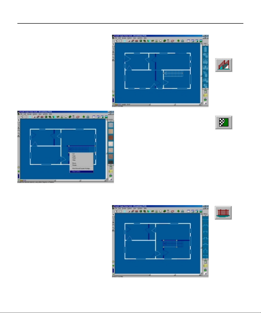
Drawing Stairs
Drawing stairs consists of two
steps.
1. Select the Stairs Tool and
Work On First Floor. The first click
will set the beginning of the stairway
and you will end them with a Rightclick. You will be able to tell which
way the stairs rise by the arrow.
Chapter 2: Tutorial
2. To create the opening in the
upper floor, select Work On Second
Floor and choose the Floor/Ground
Covering Tool. With a series of clicks
define the opening. Select the
Pointer Tool and Right-Click on the
floor area. Choose Floor Cut-Out from
the Pop-up menu to convert the floor
object to a floor cut-out.
Add a Railing
Select the Railing Tool and Work
On Second Floor. With a series of
clicks, define a railing around the
opening you created in the previous
step.
13
Page 18
Punch! Super Home Suite User’s Guide
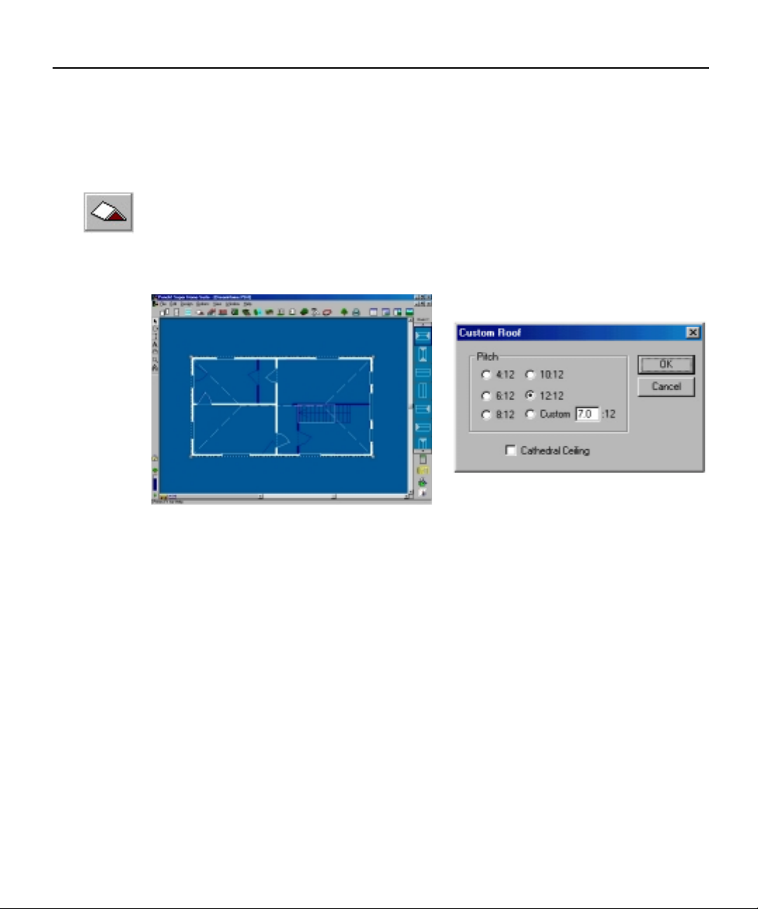
Add a Roof
Select the Roof Tool and Work on Second Floor. Using the default roof
style, Drag & Drop it into the plan window. Move it into position by selecting
the outside edge. Resize it by selecting a corner.
Right-click on the roof and change the pitch to 6:12.
Although you only need one roof section in this exercise, many floorplans
will require several.
14
Page 19
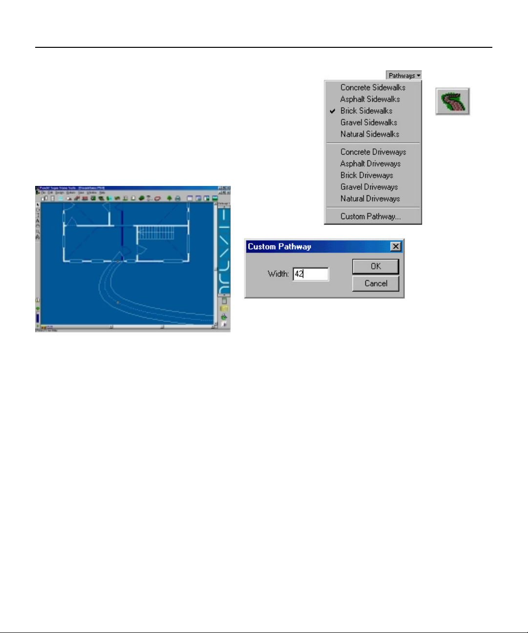
Draw a Sidewalk
Select the Pathway Tool and Work on First Floor.
With a series of clicks, define the sidewalk to the front
door, end the sidewalk with a Right-click.
Double-click on the Pathway you have just drawn
and change the width to 42” in the Custom Pathway
dialogue box.
Chapter 2: Tutorial
15
Page 20
Punch! Super Home Suite User’s Guide
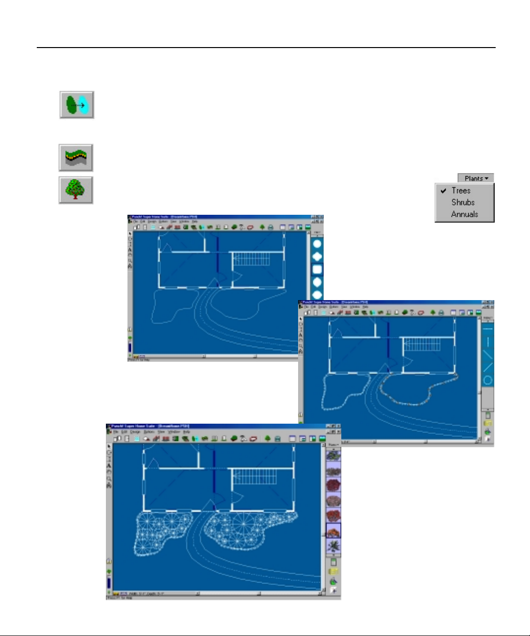
Put in a Flowerbed and edge it
Select the Fill Tool. Select the middle shape and Drag & Drop it to the left
of the sidewalk. To reshape it so that it conforms to the area’s shape, select the
individual points and move them.
Select the Edging Tool and with a series of clicks, define the perimeter of
the flowerbed, end the Edging with a Right-click.
Select the Plants Tool. Select Annuals from the Drop-Down
menu and Drag & Drop some landscape plants into the flowerbed.
16
Page 21
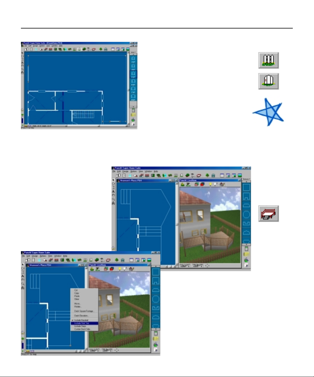
Add a deck
Select the Deck Tool and
with a series of clicks, outline
the area where you wish the
deck to be.
Right-click on each deck
section and specify whether
you want that section to
include railing, stairs, skirt
trim, etc.
Chapter 2: Tutorial
Fence the backyard
Select the Fence Tool and with a
series of clicks define the perimeter
of the area you want to fence.
Select the Gate Tool and drop in
two gates as shown.
NOTE:
The gate will
always conform
to the fence
style, if you
define the fence
as Privacy, the
gate will follow
suit.
17
Page 22
Punch! Super Home Suite User’s Guide
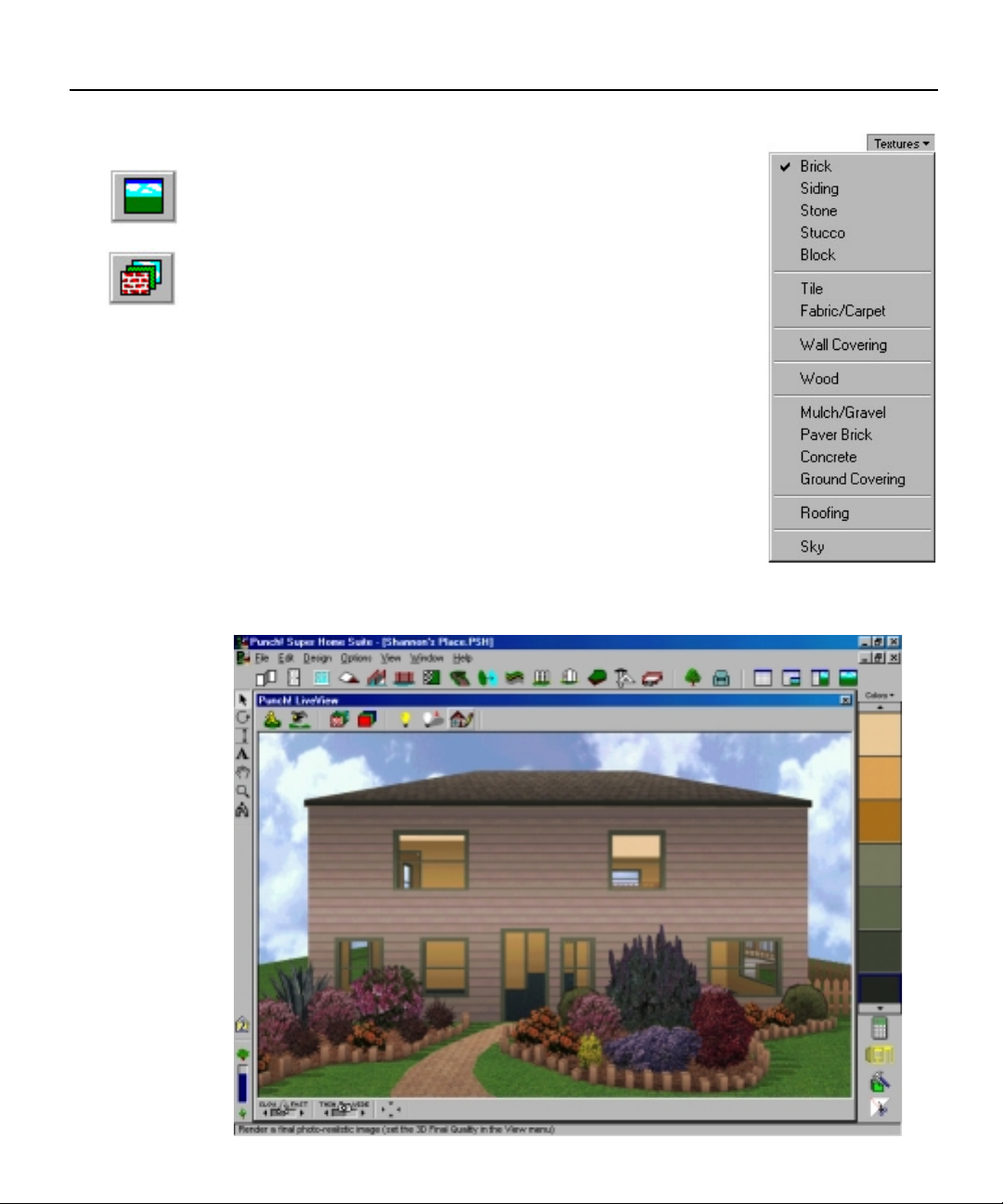
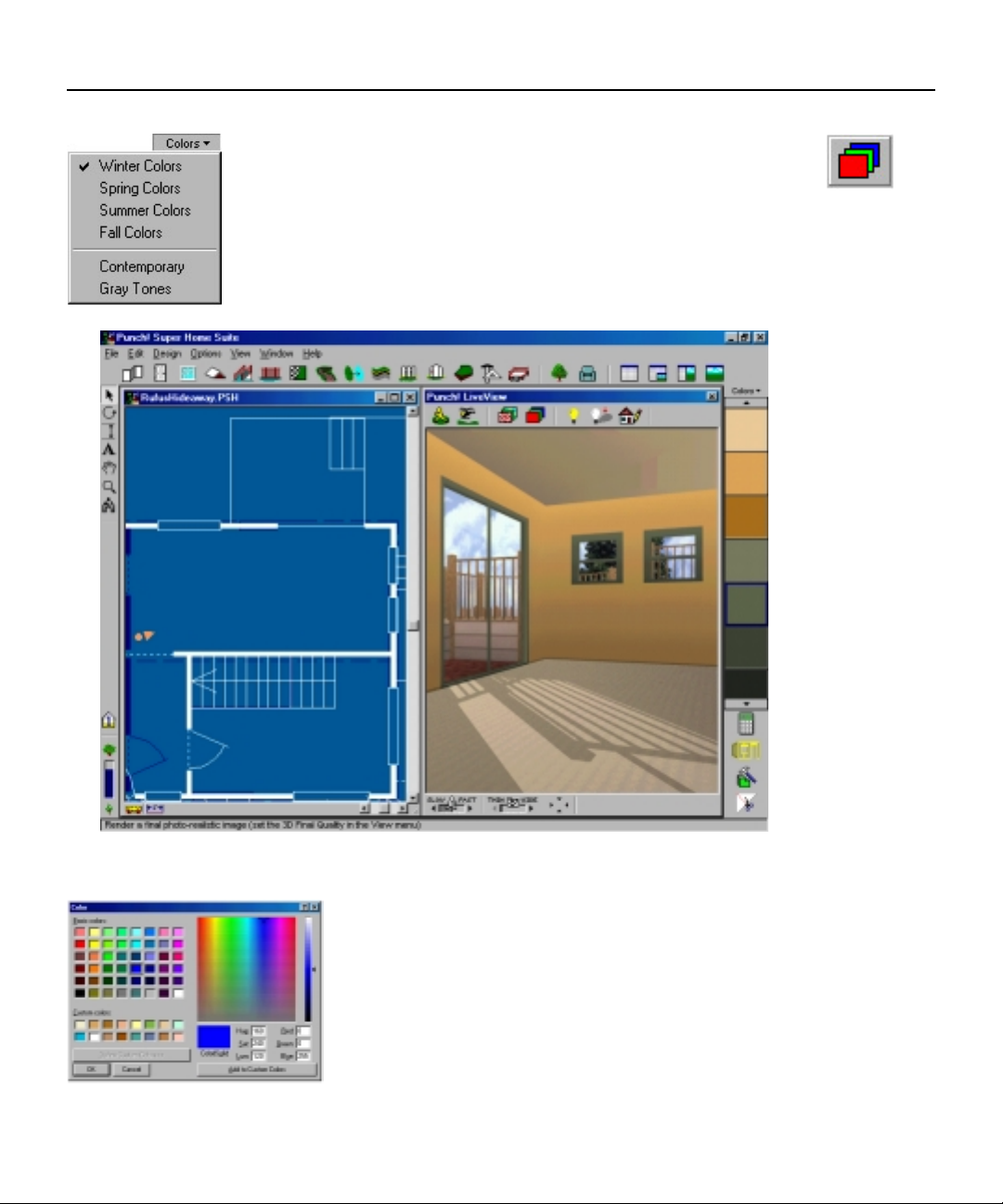
Add Colors and Textures
Activate Punch! LiveView by selecting 3D Full View
under the View menu or choosing the icon from the top
right of your window.
Select the Texture Tool. Select Siding from the Texture
Drop-Down menu. Drag & Drop the desired pattern from
the Preview Bar onto each outer wall of your design. To
expedite this process, Right-click on the color siding then
Right-click on each outer wall; end this process with a
Double-click (left mouse button).
Once you have finished the outer walls, Select Roofing
from the Texture Drop-Down menu. Drag & Drop your
choice onto the roof.
Continue this process until you are satisfied with the
outside of your design.
18
Page 23
Now, let’s move to the inside and decorate it.
Select Wood from the Texture Drop-Down menu. Drag &
Drop a selection from the Preview Bar onto the floor of the
first story to simulate hardwood flooring.
Select the Color Tool and choose a color that you find
attractive. Drag & Drop it onto the interior walls.
Chapter 2: Tutorial
You’re in no way limited to the Colors in the
Preview Window. If you Double-click on any color
you will be presented with the Color Palatte.
With this palatte you are able to duplicate any
color scheme you wish.
19
Page 24
Punch! Super Home Suite User’s Guide
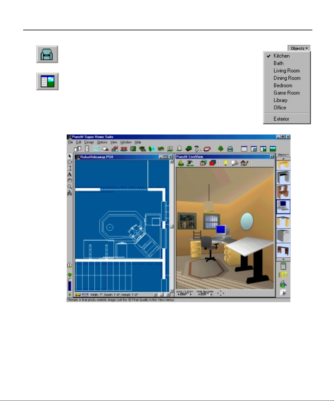
Add Objects
Select the Object Tool, choose Office from the Drop-Down
menu.
Activate the Split Plan View Window. Drag & Drop the
desired Objects into the Plan View window.
20
Page 25

Chapter three
Chapter three
PROGRAM TOOLS
Contents
Pointer Tool 22
Rotate Tool 22
Dimension Tool 22
Text Tool 23
Pan Tool 23
Zoom Tool 23
Viewpoint Tool 23
Virtual Ruler 24
Associative Dimensioning 24
Page 26
Punch! Super Home Suite User’s Guide
The Program Tools
The Program Tools are used to control the working environment. They
allow you to reduce or enlarge the view, to easily move from one part of a
drawing to another and to walk or fly through your designs.
NOTE:
Only objects
totally
encompassed by
the Click & Drag
method will be
selected.
NOTE:
Hold down the
Shift key to
release the
Rotate Tool’s
45 degree
constraint.
Pointer Tool
Use this tool to select, move or resize objects. You may select multiple objects
by holding the “Shift” key down while clicking the desired objects or you can
Click & Drag around several objects.
Rotate Tool
The Rotate Tool allows you to rotate objects. Select the Rotate Tool, then
click on what you wish to Rotate, using your mouse Rotate the Object (Wall,
Stairway, Roof, etc.) until it is in the position you require. You may also
specify a precise degree of rotation in the pop-up menu activated by a rightclick or by selecting Rotate under the Edit menu.
Dimension Tool
The Dimension Tool is used to add dimensions to areas where they are not
automatically generated. It is particularly useful when landscaping to allow
enough space between shrubs and trees. To use, Click & Drag between the
objects that are to be measured.
22
Page 27
Chapter 3: Program Tools
Text Tool
The Text Tool allows you to add labels to your floorplan. You may change the
typeface of your labeling by highlighting the text to be changed and selecting
Type from the Options menu or simply double-click on any piece of text with
the Pointer Tool.
Pan Tool
The Pan Tool makes it easy to reposition your floorplan in the 2D plan view.
When the Pan Tool is selected your cursor changes to a hand. Place the Hand
anywhere on your floorplan, then Click & Drag your floorplan to reposition it
within the viewing window.
Zoom Tool
The Zoom Tool allows you to get a close-up view of your drawing or zoom out
to view the complete floorplan. To enlarge your floorplan, hold the left mouse
button down while moving the mouse up. To reduce it, hold the left mouse
button down while moving the mouse down. The floorplan will be centered in
the window on the spot where you click.
Viewpoint Tool
The Viewpoint Tool is a unique 2D/3D navigational aid. It allows you to view
your drawing from a spot on the 2D plan. When you select the Viewpoint
Tool and click in your drawing, Punch! Super Home Suite will automatically
open a half-screen Punch! LiveView window where you will see a 3D
rendering of your floorplan.
23
Page 28
Punch! Super Home Suite User’s Guide
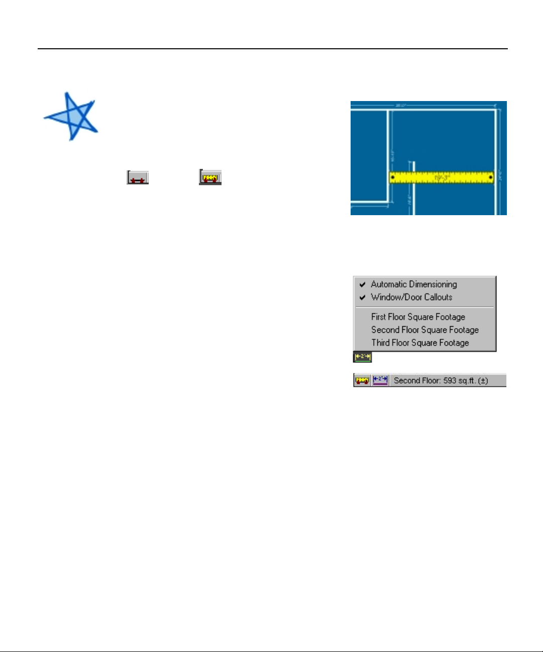
Virtual Ruler
Use the Virtual Ruler when you wish to
figure measurements that are not
automatically generated. Toggle the Virtual
NOTE:
Measurements
made with the
Virtual Ruler
will be more
accurate if you
turn off Snap to
Grid.
Ruler on and off with the icon at the bottom
left of your screen.
On Off
When the Virtual Ruler is active, position
it so it reaches the span that you wish to
measure. The measurement will appear in the middle of the Virtual Ruler.
Associative Dimensioning
The Associative Dimensioning menu
allows you to turn off and on the dimensions
of your floorplan and the dimensions of the
doors and windows.
You can also keep track of the square
footage of each floor individually. When you
select either First, Second or Third Floor
Square Footage from this menu, the
calculation will appear next to the Associative Dimensioning icon.
24
Page 29

Chapter four
Chapter four
DRAWING TOOLS
Contents
Wall Tool 26
Door Tool 28
Window Tool 30
Roof Tool 32
Stairs Tool 34
Railing Tool 37
Flooring/Ground Covering Tool 38
Pathway Tool 40
Fill Region Tool 42
Edging Tool 43
Fence Tool 44
Gate Tool 46
Topography Tool 48
CAD Tool 49
Deck Tool 50
Landscaping Tool 52
Objects Tool 54
Page 30
Punch! Super Home Suite User’s Guide
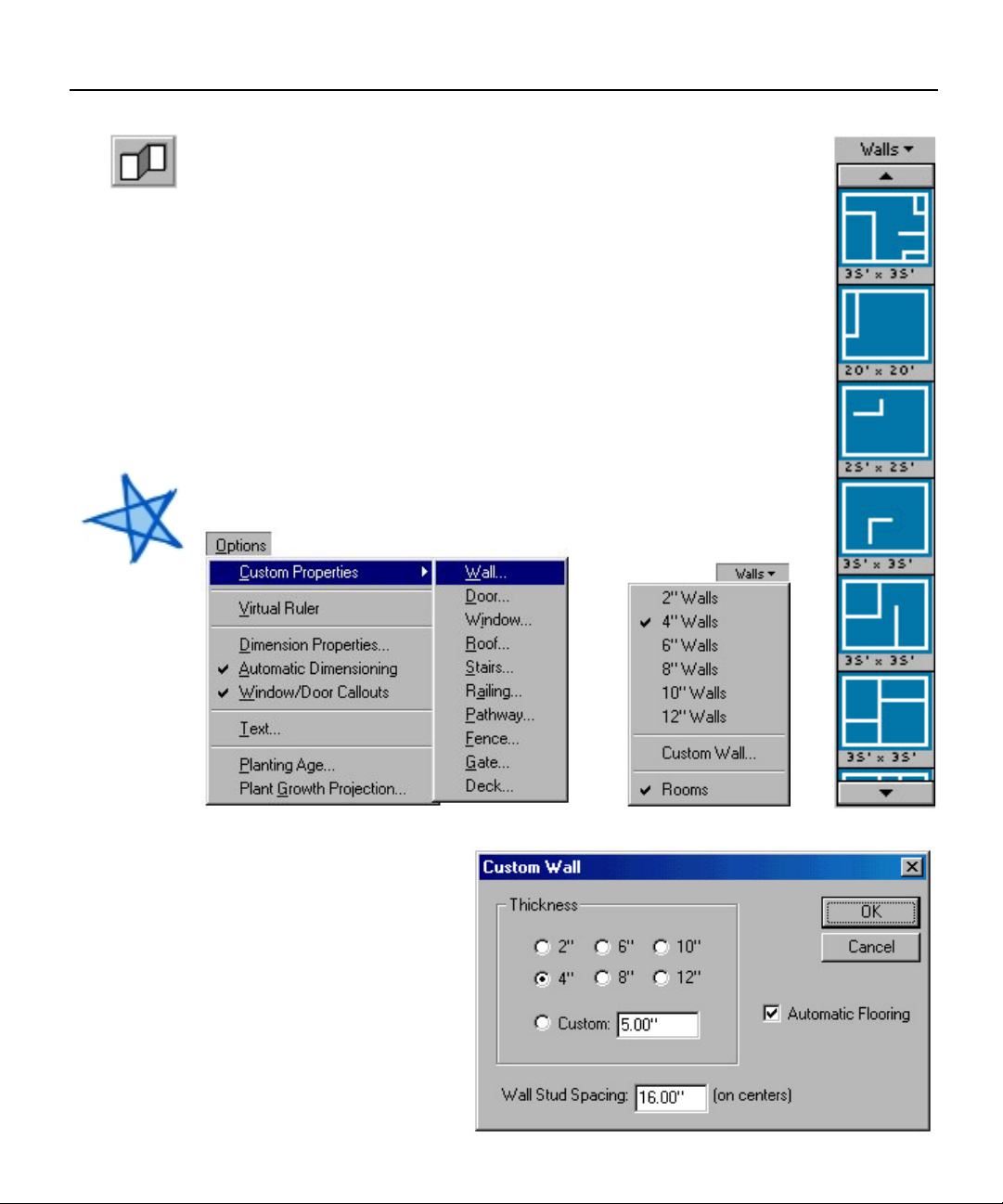
Wall Tool
When the Wall Tool is selected, previews of the available
options will appear in the Preview Bar. To change the default
settings, click on the word Walls above the previews.
You can Drag & Drop room selections from the Preview Bar or
you can manually draw a wall by placing the cursor where you
want the wall to begin, then Click & Drag until you reach the
length you desire.
A double click on any wall will cause the Custom Wall menu to
be displayed. Automatic Flooring is the default setting. By
deselecting it when you draw an upper floor, you can extend a
room up for two or three stories.
NOTE:
While you are
drawing each
floor, bear in
mind that the
perimeter must
be intact for
Punch! Super
Home Suite to
accurately
calculate square
feet. If you view
your design in
Punch!
LiveView and
you notice
“grass” growing
inside your
floorplan or you
have “carpet”
spilling outside,
there are walls
which will need
to be joined.
26
Page 31

Chapter 4: Drawing Tools
Drawing a Wall
Select the Wall Tool. Click & Drag the mouse anywhere within the design
window to draw a Wall. Release the mouse button. The Interactive
Dimensioning feature will display the length of the wall as it is being drawn.
Drawing a Perpendicular Wall
Select the Wall Tool. Click & Drag the mouse anywhere on an existing Wall
segment. Release the mouse button.
Connecting a Wall
Select the Wall Tool. Place the mouse on the end of an existing Wall. Click
& Drag the mouse to the desired length. Release the mouse button. The Wall
will join automatically. The wall must NOT be selected. When a Wall is selected,
the program will resize the Wall instead of drawing a new Wall. To de-select the
Wall, click once anywhere outside the Wall segment.
Connecting Multiple Walls
Select the Wall Tool. Place the mouse on the end of an existing Wall. Click
& Drag the mouse to the desired length. Release the mouse button over the
end of a wall segment. The Wall will trim and join automatically.
NOTE:
To release the
perpendicular
wall constraint,
hold down the
shift key while
you draw a wall.
NOTE:
Punch! Super
Home Suite
automatically
joins wall
segments and
orients walls at
right angles.
Moving Walls
Select the Pointer Tool. Select the Wall you want to move - click the
mouse button once on the Wall segment. Click & Drag on the selected Wall
segment to move it.
Resizing Walls
Select the Pointer Tool. Select the Wall you want to resize - click the
mouse button once on the Wall segment. Click & Drag on an Endpoint of the
selected Wall segment to resize the Wall. Release the mouse button.
When both endpoints are active,
you can move the wall.
When one endpoint is active,
you can resize the wall.
27
Page 32

Punch! Super Home Suite User’s Guide
Door Tool
When the Door Tool is selected, previews of the available
options will appear in the Preview Bar. To change the Preview
Library, click on the word Doors above the previews. You also
have the option of custom designing doors to your specifications.
To place a door in your drawing, select from the available
options and drag it onto a wall segment. By dragging the door
along the wall segment, you can position it according to the
Interactive Dimensioning which are the temporary dimensions
that show while you are positioning
doors, windows, etc. These
dimensions make accurate positioning
much easier and faster.
Note:
When placing
hinged doors,
the first click
places the
door and a
second mouse
click sets the
direction and
angle of the
door.
To resize a door, use the Pointer
Tool to drag one end of the door to
its new size. A double click on any
door will cause the Custom Door
menu to be displayed where you can
change door type and dimensions.
If you wish to reposition a door,
simply drag it to a new place using
the Pointer Tool.
28
Page 33

Chapter 4: Drawing Tools
“Drag & Drop” a Door
Select the Door Tool. Choose a Door style from the drop-down menu.
Select a door from the list. Click & Drag it over a wall segment, then release
the mouse button to “drop” the Door into the wall.
Placing Multiple Doors
Select the Door Tool. Choose a Door style from the drop-down menu.
Select the Door from the list. Click the mouse on a wall segment wherever you
wish to position a Door for as many Doors as you wish to place. If you are
placing hinged Doors, you will need to click once again after placing the Door.
This will set the Door’s swing angle.
Moving a Door
Select the Pointer Tool. Select the Door - click the mouse button once on
the center of a Door. Click & Drag to move the Door along the wall segment.
Release the mouse button to reposition the Door. Be sure to Click & Drag from
the center of the door. Clicking & Dragging from an endpoint of the Door will
resize it.
Resizing a Door
Select the Pointer Tool. Select the door - click the mouse button once on
the center of a Door. Click & Drag on an endpoint of the Door to resize the
Door. Release the mouse button to resize the Door. To customize a Door, RightClick on a Door and choose “Custom Door...” from the pop-up menu. Or
Double-Click on a Door to customize it.
29
Page 34

Punch! Super Home Suite User’s Guide
Window Tool
When the Window Tool is selected, previews of the available
options will appear in the Preview Bar. To change the Preview
Library, click on the word Windows above the previews. You also
have the option of custom designing windows to your
specifications.
To place a window in your drawing, select from the available
options and drag it onto a wall segment. By dragging a window
along the wall segment, you can position it according to the
Interactive Dimensioning. To place more than one window of any
kind, click on the preview then click at the various sites you wish
windows installed. When you are finished, Right-click.
To resize a window, use the Pointer Tool to drag one end of
the window to its new size. A double click on any window will
cause the Custom Window menu to be displayed.
30
Page 35

Chapter 4: Drawing Tools
“Drag & Drop” a Window
Select the Window Tool. Choose a Window style from the drop-down
menu. Select a Window from the list. Click & Drag it over a wall segment, then
release the mouse button to “drop” the Window into the wall.
Placing Multiple Windows
Select the Window Tool. Choose a Window style from the drop-down menu
as in Step 2 above. Select the Window from the list. Click the mouse on a wall
segment wherever you wish to position a Window.
Moving a Window
Select the Pointer Tool. Select the Window - click the mouse button once
on the center of a Window. Click & Drag on the center of the Window along
the wall segment. Release the mouse button to reposition the Window. Note:
Be sure to Click & Drag from the center of the Window. Clicking & Dragging
from an endpoint of the Window will resize it.
Resizing a Window
Select the Pointer Tool. Select the Window - click the mouse button once
on the center of a Window. Click & Drag on an endpoint of the Window along
the wall segment to resize the Window. Release the mouse button to resize the
Window. Note: To customize a Window, Right-Click on a Window and choose
“Custom Window...” from the pop-up menu. Or Double-Click on a Window to
customize it.
Customizing a Window
Select the Pointer Tool. Right click on the Window you wish to customize.
Enter the Width, Height, Elevation and Trim Width you want. In the Grill
section, the sliders at the right and bottom of the image control the number of
panes in the window.
31
Page 36

Punch! Super Home Suite User’s Guide
Roof Tool
When the Roof Tool is selected, previews of the available
options will appear in the Preview Bar. To change the Preview
Library, click on the word Roofs above the previews.
To place a Roof in your drawing, select from the available
options and drag it onto your design. Resize the Roof by
dragging from any corner.
You will notice that the direction of the Roof peak is
automatically created along the widest distance of the Roof. If
the peak is desired along the narrow distance, Drag & Drop the
appropriate roof from the Preview Bar and resize it after it is
drawn. Resizing will not change the direction of peak of the roof.
NOTE:
To design a flat
roof, set the
pitch to 0:12.
To move the Roof, drag it from a boundary frame. To
constrain movement to horizontal or vertical, hold the Shift key
down.
A shortcut to the Custom Roof menu is
a Right-click on the Roof you wish to
customize.
32
Page 37

Chapter 4: Drawing Tools
“Drag & Drop” a Roof
Select the Roof Tool. Select a roof pitch from the drop-down menu. Select
a Roof from the list. Click & Drag it into the design window and release the
mouse button.
Drawing a Roof
Select the Roof Tool. Select a roof pitch from the drop-down menu. Select
a Roof style from the list. Position the mouse within the design window. Click
& Drag the mouse to begin drawing the Roof. Release the mouse button to
create the Roof. If you wish to create eaves, you will want to draw your roof
slightly larger than your walls.
Moving a Roof
Select the Pointer Tool. Select the Roof - click the mouse button on the
boundary frame. Click & Drag on the boundary frame of the Roof to move it.
Release the mouse button to reposition the Roof. Note: Hold the Shift Key
down to constrain movement in horizontal & vertical directions. Be sure to
Click & Drag from the boundary frame of the roof. Clicking & Dragging from
the corner selection handles will resize it.
Note:
If you
mistakenly
draw the roof
on the wrong
floor, use the
the Move To
Floor>Upper
Floor
command in
the Edit menu.
Resizing a Roof
Select the Pointer Tool. Select the Roof - click the mouse button on the
boundary frame. Click & Drag on a corner selection handle to stretch or shrink
the Roof’s size. Release the mouse button to reposition the Roof. To customize
an existing Roof, Right-Click on an existing Roof and choose “Custom Roof…”
from the pop-up menu. Or Double-Click on a roof to customize it.
33
Page 38

Punch! Super Home Suite User’s Guide
Stairs Tool
When the Stairs Tool is selected, previews of the available
options will appear in the Preview Bar. To change the Preview
Library, click on the word Stairs above the previews.
Drawing stairs consists of two steps. The first step is drawing
the stairs themselves (or you can Drag & Drop from the Preview
Bar) and the second is defining an opening in the upper
floor for the stairs to enter.
When drawing Stairs from the 1st Floor
to the 2nd Floor, select the Stairs Tool,
make sure the 1st Floor is the active floor,
then perform a series of
TIP:
To draw a Ramp
for Wheelchair
Accessibility,
first draw a
curved Stairway.
Set the Staircase
Width to 60
inches and the
Riser Height to 0
(zero). You will
be able to
extend the Ramp
to whatever
length you need.
Select the center
point, choose
Elevate Object
from the Edit
Menu, enter half
the distance you
wish your ramp
to incline. Then
select the end
point, choose
Elevate Object
from the Edit
Menu and enter
the total height
you wish your
ramp to incline.
mouse clicks in the
direction you wish the
Stairway to rise, a right
mouse click will end the
Stairs. You will be able to
see which way the Stairs
rise by the arrows.
Drawing a Stairway
Select the Stairs Tool. Choose Straight Staircase, Curved
Staircase or Custom Staircase. Click and release the mouse button,
then drag to the desired stair length. Clicking more than one point
will create stairs with landings. Dragging one orange endpoint at an angle will
create angled stairs with landings.
Double-click to complete. In multistory designs, changing the height
of the floor will automatically
update the stair height to that
floor, the exception being if the
stairs were not drawn long enough
initially. In this case it is better to
draw stairs longer than necessary
and then adjust.
34
Page 39

Chapter 4: Drawing Tools
Create an Opening for the Stairs
After drawing a stairway, you may need to
“cut an opening” in the floor above. Select
Work on Second Floor (or Third Floor, if
applicable) from the Design drop-down menu.
Choose the Floor/Ground Cover Tool. With a
series of clicks, outline the floor area where
you want the cut-out to be. Right-click after
placing the last point to close the floor area.
Select the Pointer tool and Right-Click on
the floor area you just outlined. Choose Floor
Cut-Out from the Pop-up menu to convert the floor object to a floor cut-out.
NOTE:
Floor cut-outs
will not appear
when moving in
3D. They will,
however, appear
after movement
is stopped.
“Drag & Drop” a Stairway
Select the Stairs Tool. Select a Stairway from the list. Click & Drag it into
the design window and release the mouse button.
Moving a Stairway
Select the Pointer Tool. Click on any part of the staircase direction arrows
other than the orange endpoints. Click & Drag the stairs to the desired location
within the file.
35
Page 40

Punch! Super Home Suite User’s Guide
Resizing a Stairway
Select the Pointer Tool. Click on any part of the staircase direction arrows
other than the orange endpoints. Drag the endpoint(s) to extend or shorten
note:
You can control
the number of
steps by
changing the
Riser Height in
the Custom
Staircase menu.
The default
number of steps
is the Floor
Height (set in
Design>Floor
Heights)
divided by the
Riser Height.
While it is
possible to draw
a staircase that is
shorter than the
ceiling, it is not
possible to draw
a stairway which
extends above
the ceiling.
the length of the staircase. The program will automatically stop the stairs at
the next floor level.
Customizing a Stairway
Select the Pointer Tool. Right-click or double-click on any part of the
staircase direction arrows other than the orange endpoints. Staircase width,
riser height, tread width and handrail options can be changed from this dialog
box.
Drawing & Resizing a Curved Staircase
Select the Staircase Tool. Choose Curved Staircase. Click and release the
mouse button, determine the arc size of the staircase, then click again. To
change staircase arc, click any orange endpoint and drag. Double-click to
access customized properties such as staircase width, riser height, tread width
and handrail options.
36
Page 41

Chapter 4: Drawing Tools
Railing Tool
When the Railing Tool is selected, previews of the available
options will appear in the Preview Bar. To change the Preview
Library, click on the word Railing above the previews.
Draw your Railing by performing a series of mouse clicks, a
right mouse click will end the Railing.
A double click on any part of the Railing will cause the
Custom Railing menu to be displayed.
Drawing a Railing
Select the Railing Tool. Choose Straight Railing, Curved Railing or Custom
Railing. Click and release the mouse button, then drag to the desired rail
length. Right-click to complete.
Moving a Railing
Select the Railing Tool. Click on any part of the dashed line. Two orange
endpoints will appear. Click & Drag the railing to the desired location within
the file.
37
Page 42

Punch! Super Home Suite User’s Guide
Flooring/Ground Covering Tool
When the Flooring/Ground Covering Tool is selected,
previews of the available options will appear in the Preview Bar. To
change the Preview Library, click on the word Flooring above the
previews.
By performing a series of mouse clicks, outline the area where
you wish the Flooring/Ground Covering to be placed. A right
mouse click will end the area.
“Drag & Drop” Floor/Ground Cover
Select the Flooring/Ground Covering Tool. Choose either
Interior Flooring or Exterior Ground Covering. Click & Drag an
entry from the list of Flooring/Ground Covering styles. Release the
mouse button anywhere in the 2D plan view. Resize this shape
using the orange endpoints.
38
Page 43

Chapter 4: Drawing Tools
Drawing Custom Floor/Ground Cover
Select the Flooring/ Ground Covering Tool. Then choose either Interior
Flooring or Exterior Ground Covering. Position the mouse within the design
window. Click the mouse button once to set the first point of the Floor/
Ground perimeter. With a series of clicks, outline the Floor/Ground perimeter.
After placing the final perimeter point, Right-Click to end. The final perimeter
point will automatically be connected to the first point to complete the shape.
Moving Floor/Ground Cover
Select the Pointer Tool. Select the Floor/Ground perimeter by clicking on
the boundary frame. Click & Drag on the boundary frame to move the Floor/
Ground Covering. Release the mouse button to reposition the Floor/Ground
Covering. Note: Hold the Shift Key down to constrain movement in horizontal
& vertical directions. Be sure to Click & Drag from the boundary frame of the
Floor/Ground Covering. If you Click & Drag from the corner selection handles
the area will be reshaped.
Reshaping Floor/Ground Cover
Select the Pointer Tool. Select the Floor/Ground perimeter by clicking on
the boundary frame. Click & Drag on a point selection handle to reshape the
Floor/Ground Covering. Release the mouse button to reposition the Floor/
Ground Covering.
Note:
You can
temporarily
deactive the
horizontal &
vertical
constraint by
holding down
the Shift Key
while drawing.
39
Page 44

Punch! Super Home Suite User’s Guide
Pathway Tool
When the Pathway Tool is selected, previews of the available
options will appear in the Preview Bar. To change the Preview
Library, click on the word Pathways above the previews.
You can either Drag & Drop a Pathway from the Preview Bar
or draw one to meet your individual needs. Draw a Pathway by
performing a series of mouse clicks, a right mouse click will end
the Pathway. Selecting the Custom Pathway option will display
this menu:
40
Page 45

Chapter 4: Drawing Tools
“Drag & Drop” a Pathway
Select the Pathway Tool. Choose a Pathway or Driveway Option from the
drop-down menu. Click & Drag an entry from the list of Pathway styles.
Release the mouse button anywhere within the design window.
Drawing a Custom Pathway
Select the Pathway Tool. Then choose from the listing of Pathway styles.
Position the mouse within the design window. Click the mouse button once to
set the first point of the Pathway. Move the mouse to the location for the next
Pathway point and click to set that point. Repeat this step until all the
Pathway points have been set. After placing the final Pathway point, RightClick to end.
Moving a Pathway
Select the Pointer Tool. Select the pathway by clicking on the center-line.
Click & Drag on the center-line to move the pathway. Release the mouse
button to reposition the pathway.
Reshaping a Pathway
Select the Pointer Tool. Select the Pathway by clicking on the center-line.
Click & Drag on a point selection handle to reshape the Pathway. Release the
mouse button to reshape the Pathway.
Note:
Hold the Shift
Key down to
constrain
movement in
horizontal &
vertical
directions. Be
sure to Click &
Drag from the
center-line of
the Pathway.
Clicking &
Dragging from
the corner
selection handles
will reshape it.
41
Page 46

Punch! Super Home Suite User’s Guide
Fill Region Tool
When the Fill Region Tool is selected, previews of the
available options will appear in the Preview Bar. To change the
Preview Library, click on the word Fills above the previews.
You can either Drag & Drop a shape from the Preview Bar or
draw one to meet your needs. Use this feature to
provide interesting planting beds in your
Landscape or a fun Playground for the kids.
“Drag & Drop” Fill Regions
Select the Fill Region Tool. Choose a Fill style from the drop-
down menu. Drag & Drop an entry from the list of Fill Regions.
Release the mouse button anywhere within the design window.
Note:
Hold the Shift
Key down to
constrain
movement in
horizontal &
vertical
directions.
Drawing Fill Regions
Select the Fill Region Tool. Then choose from the listing of
Fill styles. Position the mouse within the design window. Click &
Drag the mouse to draw the desired Fill Region size. Release the
mouse button to create the Fill Region. This will draw round Fill
Regions, create elliptical regions by holding the Shift Key down.
Moving Fill Regions
Select the Pointer Tool. Select the Fill Region by clicking on the boundary
frame. Click & Drag on the boundary frame to move the Fill Region. Release the
mouse button to reposition the region. Be sure to Click & Drag from the
boundary frame of the Fill Region. Clicking & Dragging from the point selection
handles will reshape it.
Reshaping Fill Regions
Select the Pointer Tool. Select the Fill Region by clicking on the boundary
frame. Click & Drag on the point selection handle to reshape the Fill Region.
Release the mouse button to reposition the region.
42
Page 47

Chapter 4: Drawing Tools
Edging Tool
When the Edging Tool is selected, previews of the available
options will appear in the Preview Bar. To change the Preview
Library, click on the word Edging above the previews.
You can either Drag & Drop an Edging from the Preview Bar
or draw one to meet your needs.
Draw an Edging by performing a series of mouse clicks, a
right mouse click will end the Edging.
“Drag & Drop” Edging
Select the Edging Tool. Choose an Edging style from the
drop-down menu. Click & Drag an entry from the list of Edging
shapes. Release the mouse button anywhere within the design
window.
Drawing Custom Edging
Select the Edging Tool. Then choose from the listing of
Edging styles. Position the mouse within the design window.
Click the mouse button to set the first point of the Edging.
Move the mouse to the location for the next Edging point and
click to set that point. Repeat this step until all the Edging points have been
set. After placing the final edging point, Right-Click to end the Edging
drawing.
Reshaping Edging
Select the Pointer Tool. Select the Edging by clicking on the center-line.
Click & Drag on the point selection handles. Release the mouse button to
reshape the Edging. To customize an existing Edging, select the Edging, RightClick then choose “Custom Edging...” from the pop-up menu. Or simply
Double-Click on the Edging.
43
Page 48

Punch! Super Home Suite User’s Guide
Fence Tool
When the Fence Tool is selected, previews of the available
options will appear in the Preview Bar. To change the Preview
Library, click on the word Fencing above the previews.
You can either Drag & Drop a Fence from the Preview Bar or
draw one to meet your needs.
Draw a Fence by performing a series of mouse clicks, a right
mouse click will end the Fence.
Tip:
You can Drag &
Drop Textures
onto your Fence,
to further
customize it.
44
Page 49

Chapter 4: Drawing Tools
“Drag & Drop” Fencing
Select the Fencing Tool. Choose a Fencing style from the drop-down menu.
Click & Drag an entry from the list of fencing shapes. Release the mouse
button anywhere within the design window.
Drawing Fencing
Select the Fencing Tool. Then choose from the listing of Fencing styles.
Position the mouse within the design window. Click the mouse button to set
the first point of the Fencing. Move the mouse to the location for the next
Fencing point and click to set that point. Repeat this step until all the Fencing
points have been set. After placing the final fence point, Right-Click to end
the fence drawing.
Reshaping Fencing
Select the Pointer Tool. Select the Fencing by clicking on the boundary
frame. Click & Drag on the point selection handles to reshape the Fence.
Release the mouse button to reshape the fence. To customize an existing fence,
select the Fence, Right-Click then choose “Custom Fence...” from the pop-up
menu. Or simply Double-Click on the Fence.
Note:
Hold the Shift
Key down to
constrain
movement in
horizontal &
vertical
directions.
45
Page 50

Punch! Super Home Suite User’s Guide
Gate Tool
When the Gate Tool is selected, previews of available Gate
widths will appear in the Preview Bar.
Simply Drag & Drop a gate into your existing fence.
NOTE:
When you place
a Gate on an
existing fence,
the Gate will
always conform
to the type of
fencing used;
i.e., if it is a
Privacy Fence, a
Privacy Gate will
be placed.
46
Page 51

Chapter 4: Drawing Tools
“Drag & Drop” a Gate
Select the Gate Tool. Choose a standard-sized Gate. Click & Drag an entry
from the list. Release the mouse button over a fence segment to place the
Gate. Note: The Gate’s style will be the same style as the fence receiving the
Gate. To specify a custom Gate size, select “Custom Gate...” from the dropdown menu and type in the desired width.
Placing Multiple Gates
Select the Gate Tool. Click once on a standard-sized Gate. Place the mouse
on a fence segment and click to position a Gate. Click along the fence wherever
you wish to place a gate.
Moving a Gate
Select the Pointer Tool. Select the Gate by clicking in the center of it.
Click & Drag on the center to move the Gate along the fence. Release the
mouse button to move the Gate. Note: Be sure to Click & Drag from the center
of the Gate. Clicking & Dragging from the end-points will resize it.
Resizing a Gate
Select the Pointer Tool. Select the Gate by clicking in the center of it.
Click & Drag on an end-point to resize the Gate. Release the mouse button to
resize the Gate.
47
Page 52

Punch! Super Home Suite User’s Guide
Topography Tool
When the Topography Tool is selected, previews of the
available options will appear in the Preview Bar. To customize the
topography grade, click on the word Topo above the previews and
choose Custom Topography. You will be presented with the
following dialogue box. Enter the rise (or fall) you wish to create.
TIP:
To build a splitlevel home or a
home with a
basement, use
the Topography
Tool to “build
up” the land
around your
First Floor. In the
case of a
basement, the
Second Floor will
become the
ground level
floor and the
Third Floor will
be the second
story.
“Drag & Drop” Topography
Select the Topography Tool. Choose a standard Topography
shape. Click & Drag an entry from the list. To set the actual “lay-
of-the-land” choose “Custom Topography...” Then raise and lower
the values of each layer in the pop-up menu. Topography with the
“+” sign indicate hills and the “–” sign indicates valley.
Drawing Topography
Select the Topography Tool. Position the mouse within the
design window. Click the mouse button to set the first point of
the new Topography. Move the mouse to the location for the next
Topography point and click to set that point. Repeat this step
until all the Topography points have been set. After placing the final
Topography point, Right-Click to end the Topography drawing.
48
Page 53

Chapter 4: Drawing Tools
Moving Topography
Select the Pointer Tool. Select the Topography by clicking on the
boundary frame. Click & Drag on the boundary frame to move the selected
area. Release the mouse button to reposition the region.
Reshaping Topography
Select the Pointer Tool. Select the Topography by clicking on the
boundary frame. Click & Drag on the point selection handles to reshape the
Topography. Release the mouse button to reshape the area.
CAD Tool
The CAD Tool is especially useful when diagramming things
that you don’t wish to appear in the 3D views. It allows geometry
like plumbing, electrical, HVAC, outdoor sprinkler systems, etc., to
be placed.
Note:
To draw a
straight line,
place many
points just a few
inches apart.
“Drag & Drop” CAD
Select the CAD Tool. Choose a standard shape. Click & Drag an
entry from the list.
Reshaping CAD
Select the Pointer Tool. Select the CAD Geometry item by
clicking on the boundary frame. Click & Drag on the point
selection handles to reshape the CAD item. Release the mouse
button to reshape the area.
49
Page 54

Punch! Super Home Suite User’s Guide
Deck Tool
When the Deck Tool is selected, previews of the available
options will appear in the Preview Bar.
You can Drag & Drop a Deck from the Preview Bar or draw one
to meet your needs.
Draw a Deck by performing a series of mouse clicks. A post
NOTE:
To constrain the
decking to
horizontal or
vertical, hold the
Shift key down.
will appear in the railing at the location of each click. You have
the option of specifying Skirting, Steps and Railing for each
deck section. You also have the option of elevating the deck.
By Right-clicking on any Deck piece and selecting Custom
Deck Side from the menu, you will be able to change the
Skirting, Step and Railing options for the entire deck.
To add a Deck to the Second Floor, draw the deck on the
First Floor and specify an elevation equal to the ceiling height of
your first floor. Right click on the deck piece where you wish to
add stairs and specify the Total Height equal to the elevation.
50
Page 55

“Drag & Drop” A Deck
Select the Deck Tool. Choose a Deck style from the Preview Bar. Click &
Drag it into position in the design window. Release
the mouse button anywhere within the design
window.
Chapter 4: Drawing Tools
Drawing A Deck
Select the Deck Tool. Position the mouse within
the design window. Click the mouse button to set
the first post for the deck. Move the mouse to the
location for the next post and click to set that
point. Right click on each Deck piece and specify if it
needs skirting, steps or railing.
Reshaping A Deck
Select the Pointer Tool. Select the Deck by
clicking on the boundary frame. Click & Drag on a
point selection handle to reshape the Deck. Release the mouse button to
reshape the Deck.
Tip:
The Interactive
Dimensioning
feature will be
very handy
during Deck
design. You will
be able to space
posts exactly as
far apart as the
building code in
your area
requires.
51
Page 56

Punch! Super Home Suite User’s Guide
Landscaping Tool
When the Landscaping Tool is selected,
previews of the available options will appear in the
Preview Bar. To change the Preview Library, click
on the word Plants above the previews.
Drag & Drop your choice of
plants into your 2D design window. To further
customize your Landscape settings, select Planting
Age under the Options Menu. You can select a
different Planting Age for each plant you choose.
Enter the age you wish the plants to be when
they are placed in the design. Then select Plant
Growth Projection from the Options Menu.
Enter the maximum age that plants may be
grown to represent. The default is 20 years. The
minimum is 3 months and the maximum is 50 years.
52
Punch! Super Home Suite also allows you the unique ability
to watch your plants grow! To grow your plants, select the Plant
Growth Scale located in the lower left portion of your screen.
By depressing the left mouse button on the upper tree, you
will increase the age and size of your landscape plantings. By
depressing the left mouse button on the lower tree, you will
decrease the age and size of your landscape plantings.
Page 57

To view the Plant Details of
individual plants, Double-click
on them.
By using a combination of the many tools available with Punch!
Super Home Suite you can create beautiful landscapes, like this:
Chapter 4: Drawing Tools
53
Page 58

Punch! Super Home Suite User’s Guide
Objects Tool
When the Objects Tool is selected, previews of the available
options will appear in the Preview Bar. To change the Preview
Library, click on the word Objects above the Previews.
Punch! Super Home Suite includes
hundreds of pre-drawn objects. You can Drag &
Drop these objects into your 2D design window.
If you want to change the finish on the
cabinets, you can Drag & Drop any Texture or
Note:
To place an Object
on top of another
Object, like a
toaster on a
counter or a lamp
on a table, use the
Elevate Object
command. This
command is easily
accessed by
Right-clicking on
the Object itself.
Color onto them in Punch! LiveView.
You can further customize any of these
objects with Punch! 3D Furniture
Workshop (see Chapter 9). Double-click
on any Object and this will
automatically launch Punch! 3D
Furniture Workshop or Right-click on
the object you with to customize and
select 3D Furniture Workshop.
54
Page 59

Chapter five
Chapter five
MENU BARS
Contents
The File Menu 56
The Edit Menu 57
The Design Menu 59
The Options Menu 61
The View Menu 63
The Window Menu 65
The Help Menu 65
Page 60

Punch! Super Home Suite User’s Guide
The File Menu
The commands under the File Menu are those that allow file creation; opening, closing, importing and exporting files; saving files; printing features and launching the supporting programs.
New (Ctrl+N) opens a new, untitled
window. Open (Ctrl+O) displays the Open
dialog box, which lets you open an existing
floorplan. Close (Ctrl+W) closes the active
window.
Save (Ctrl+S) saves the changes you
have made since opening your drawing. If
you began a new drawing, this command
will display the “Save As” Dialogue box and you will be prompted to give your
drawing a name. Save As... allows you to save your drawing at various stages
of completion. This command is especially useful if you wish to “try out”
different room or landscaping ideas.
56
Launch 3D Furniture Workshop opens a new Punch! 3D Furniture
Workshop window. 3D Furniture Workshop is a powerful CAD program that
allows you to create your own furniture or edit the existing furniture objects.
You may also open 3D Furniture Workshop by clicking on the icon in the
lower right of your window.
Launch RealModel opens Punch! RealModel and loads the currently open
drawing. Punch! RealModel® (patent-pending) is a program that allows you
to construct an actual scale model of your dream home.
Launch Home Estimator opens Punch! Home Estimator worksheet and
calculates the materials used in the currently open drawing in an editable
format.
Page 61

Chapter 5: Menu Bars
Import allows you to import your
custom-designed furniture and fixtures
from 3D Furniture Workshop. Export
allows you to export the contents of
your Punch! LiveView window in either BMP
or DXF format. Choose the directory where
you wish to save the image, The default
directory is the “My Documents” folder, but
you can save the image in another directory if you prefer. The BMP file can be
printed using MS Paint.
Print to Fit Page (Ctrl+P) displays the Print dialogue box. You will have a
choice of which printer to use and how many copies of your drawing you wish
to print. Print to Scale prints your 2D floorplan in the scale that you have
chosen.
Exit closes the Punch! Super Home Suite program. You will be prompted
to save your work.
The Edit Menu
Commands contained under the Edit Menu are those that allow
alterations to items that you have drawn. It contains the standard
Windows commands, in addition to Punch! Super Home Suite
specific commands.
Undo remembers the last step that was taken and allows you to
erase it. Once you have used the Undo command you have the
option of “Redoing” the change. Undo is not available for every
action.
Cut (Ctrl+X) removes the selected item(s) to the Clipboard. Cut is
unavailable if nothing is selected. Copy (Ctrl+C) places a duplicate of
the selected item(s) on the Clipboard. Copy leaves the original in
place. Copy is unavailable if nothing is selected. Paste (Ctrl+V) places
the contents of the Clipboard into your drawing. You may place the
Clipboard contents as many times as you wish. This command is unavailable if
the Clipboard is empty.
Clear (Delete) removes the selected item(s) from your drawing. The item is
not stored on the Clipboard and its action cannot be undone.
57
Page 62

Punch! Super Home Suite User’s Guide
Select All (Ctrl+A) will select every item on the currently active floor.
Copy To Floor allows you to place a duplicate of
the selected object(s) on a different floor. Like the
copy command, it leaves the original in place.
Move To Floor allows you to relocate selected
object(s) to a different floor. Like the cut command, it
does not leave the original in place.
Nudge allows you to move objects in definable
increments. The Up, Down, Left and Right selections
can also be activated by the arrow keys on your
keyboard. Through the Distance dialogue box,
distances as small as 1 inch may be defined.
Move allows for a very precise placement. A
dialogue box will be displayed asking you to specify
how far you wish to move the selected object(s) and by
which method. The Cartesian method uses the X and Y
coordinates for definition and the Polar method uses
Distance and Angle to specify the move.
58
Rotate will display a dialogue box asking you to
specify the angle of rotation and the method. The object
rotates on its center.
Use the Elevate Object command when you need
to “lift” something onto a table or raise the floor on
your new deck. Elevation is measured in inches and
you may enter a negative number by adding the
minus sign (-) if you wish to lower the object. The
Elevate Roof command is especially useful when you
decide to add a second floor after drawing the roof.
Elevation is measured in inches and you may enter a
negative number by adding a minus sign (-) to lower
the roof.
Page 63

Chapter 5: Menu Bars
The Design Menu
The commands available through the Design Menu
give you control of your floorplan environment. From the
scale at which you are drawing, to ceiling height, to
defining a custom background color.
The Grid Properties (Ctrl+G) option is available to
give you more control over your drawing. By default, the
grid is set at twelve inches; this way you can visualize
that each square on the floorplan is 1 square foot. By
defining a customized Grid, you can design to fit your
specific needs.
You may choose to define a different Grid Spacing or
a smaller Snap Grid for more precise drawing. The choices
for Grid Style are dots or lines, depending on your
preference. Grid Visible toggles the grid on and off.
The Snap to Grid (Ctrl+R) option lets you quickly align items. When Snap
to Grid is checked and you Drag & Drop an object, the object aligns
automatically with the grid. By default, Snap to Grid is checked. The snap to
distance is specified in the Grid Spacing field of the Grid Properties dialogue
box.
The Lot Size (Ctrl+L) option allows you to define a “virtual lot” that more
closely resembles your “physical lot”. You may use either feet or meters as your
unit of measure.
Punch! Super Home Suite creates an actual scale drawing of your
floorplan. The default Plan Scale is 1/3"=1', which means that 1/3 inch on
your design equals one foot in the real world. When you print out your
floorplan, using the Print to Scale option, it will also be at the chosen scale.
Unit of Measure. You may choose to work using English (feet and inches)
or Metric (meters and centimeters) measurements.
NOTE:
To draw a lot
which is not
rectangular (a
cul de sac, for
example), set the
dimensions at
your lot’s largest
point, then use
the CAD Tool to
draw the
irregular edges
59
Page 64

Punch! Super Home Suite User’s Guide
between floors, you can always keep track of which one is active
by the little house in the lower left corner. You can also change
working floors by clicking on the little house and selecting from
the menu.
The Work on Floor option allows
you to choose between the First
Floor, Second Floor or Third Floor.
Both the 2D and 3D views will be
affected by this choice. As you switch
The Visible Floors option allows
you to display either the floor
currently under construction or all
floors of your design. Both the 2D and 3D views will be
affected by this choice.
The Floor Heights option allows you to
set custom ceiling heights for each floor of
your design. You may define the First
Floor, Second Floor and Third Floor
independently of each other. The default
ceiling height is 96 inches (8 feet).
The Square Footage option
allows you to calculate the
square footage of each floor in
your design. It can be accessed from the Design drop-down
menu or by clicking on the icon at the bottom of your
screen.
60
Page 65

Chapter 5: Menu Bars
Floorplan Trace is a powerful tool that will get you
started fast; it lets you easily scan, load and trace existing
plans. Load Floorplan Trace Image... allows you to
import a scanned .bmp file into the background of your
design. Resize Floorplan Trace Image... allows you to
match the scale of your design window. Floorplan Trace
Image Visible toggles the image on and off.
When you select Screen Colors,
you will have the option of changing
the color for the Working Floor,
Inactive Floor, or Background; plus you can Reset Colors to their
default. By defining each option, you will be able to tell at a glance
which floor is currently active. The Working Floor Color default is
white, the Inactive Floor Color default is dark blue, and the Background
Color default is blue. The colors you define will remain with the program until
you assign new colors or use the Reset Colors feature which sets all custom
colors back to the program-defined defaults.
The Options Menu
The commands available through the Options Menu
allow further customization of the drawing
environment.
Custom Properties: To further personalize your
dream home, virtually every tool has custom settings.
See Chapter 4 for the full description of each tool’s
custom properties.
Use the Virtual Ruler when you wish to
figure measurements that are not automatically
generated. Toggle the Virtual Ruler on and off
via the icon at the bottom left of your screen.
By selecting Dimension Properties, you
have the option of changing the endpoints of the
measurements drawn with the Dimension Tool to
suit your needs. This option only changes the
endpoints.
61
Page 66

Punch! Super Home Suite User’s Guide
When the Automatic Dimensioning option is selected, all
items will be shown with their measurements. You can also turn
on and off Automatic Dimensioning with the Associative
Dimensioning icon at the bottom part of your screen.
When the Window/Door Callouts option is checked, the measurements of
all window and door openings will be added to the wall measurements.
You can also turn on and off Window/
Door Callouts with the Associative
Dimensioning icon
at the bottom part
of your screen.
62
When selected, the Text option will display a
dialogue box where you can select the font, style
and size of the Text that you use to label your
floorplan. When you change the display font, all
text in your drawing will be updated.
Page 67

Chapter 5: Menu Bars
Planting Age. When you are
landscaping your dream home, you have
the option of deciding what age the
plants will be when they are
transplanted into your landscape. Unless
otherwise specified, all plants are 0 years
(seedlings). The maximum age that can
be entered into this dialogue box is 20
years.
The Plant Growth Projection
dialogue box allows you to specify the
maximum growing age (in years) for the plants you choose for your landscape.
The default is 20 years. The minimum is 3 months and the maximum is 50
years.
The View Menu
The View Menu contains selections which change the way
your drawing is displayed in the Punch! LiveView window.
Note:
You can define
the Planting
Age for each
individual plant
to further
customize your
landscape.
Reset Floor Plan (Ctrl+E) returns the floorplan to the
center of the window and to 60% of actual size. When Set Plan
View Zoom is selected, a window is displayed that allows you to
choose how large your 2D floorplan is displayed. Reset 3D
View returns the 3D plan view in the LiveView window to the
default setting.
3D Framing Phase and 3D Completion Phase are two ways
to view your drawing in the LiveView window.
63
Page 68

Punch! Super Home Suite User’s Guide
Render 3D Final Quality. You may choose to view your
home in Final Quality at any time. Your home will be displayed
Hide Doors in 3D View allows you to choose whether your floorplan
NOTE:
You can interrupt
any rendering at
any time with a
click of the
mouse. You do
not have to wait
until a render is
completed to
continue
drawing.
3D Lighting allows you to control how
the shadows fall in your design. Select the
direction you wish the light to come from
and how bright you wish the light to appear.
in the LiveView window with a much sharper
appearance.
3D Final Quality. Allows you to control
the speed at which Punch! Super Home
Suite renders your drawing.
3D Viewing Method allows you to
control how you move through your
design. In addition to this menu, you
can control elevation by holding the
right-mouse button down.
renders with or
without doors in the
Punch! LiveView
window. It is
especially useful in
smaller rooms, where
the door might
obscure much of the
viewing space.
64
3D Shadows allows you to include
rendered shadows in your LiveView window.
Refresh enables you to redraw the screen
and refresh the design information in your
drawing.
Page 69

The Window Menu
The Window Menu contains the controls for Punch! LiveView,
the different viewing methods and the open file list.
The Punch! LiveView window allows you to see what your
design looks like in 3D. You can move through your design with
either the Walk-Thru Tool or the Fly-Around Tool.
It is in the Punch! LiveView window that you apply textures
and colors and watch your Landscape grow!
Plan Full View. The default is Plan Full View. When you load
Punch! Super Home Suite, this is the view you will see.
3D Quarter View allows you to use most of your screen for drawing, yet
be able to view your design in 3D.
Split Plan/3D View allows you to focus primarily on your 3D actions while
maintaining a clear view of the 2D design.
Chapter 5: Menu Bars
3D Full View is primarily for detail design like the application of Textures
or Colors. You will also find this a useful view when you are Landscaping your
yard. You will easily see everything from every angle.
Open Window Listing will display a listing of all open drawings.
The Help Menu
Contents... [F1] displays the on-line Help File.
Search... allows you to search for a specific topic in
the Help File.
Using Help... explains how to use Help.
About Punch! Super Home Suite displays the program’s splash screen.
65
Page 70

Chapter six
Chapter six
ENVIRONMENT
Contents
™
LIVEVIEW
Walk-Through Tool 68
Fly-Around Tool 68
Applying Textures & Colors 69
Lighting & Shadows 71
Viewing Speed 73
Camera Angle 73
Viewpoint Direction Arrows 74
Punch! LiveView Size Options 75
Page 71

Punch! Super Home Suite User’s Guide
Walk-Through Tool
The Walk-Through Tool is one mode of navigating in 3D around your
house. In the Punch! LiveView window, simply move the mouse where you
wish to “walk”. The greater the movement of the mouse, the faster the pace.
The elevation may also be changed by selecting 3D Viewing Method>
Walk-Through Elevation... under the View menu. To change the elevation of
the view in Walk-Through mode, hold the right mouse button down.
Fly-Around Tool
The Fly-Around Tool is another way to move directly through your 3D
design. The left mouse button controls up, down, left and right movement,
while the right mouse button zooms in and out for a close-up or bird’s eye
view. The altitude may also be changed by selecting 3D Viewing Method>
Fly-Around Altitude... under the View menu.
In addition to the
icons, these options are
available through the View
Menu. By selecting 3D
Viewing Method, you may
choose between Walk-Through or Fly-Around mode and specify at what
elevation or altitude you want to work.
68
Page 72

Chapter 6: The LiveView Window
Applying Textures & Colors
Punch! Super Home Suite provides the tools to apply a wide
variety of Textures and Colors to customize your design. The only
requirement for applying them is that you are working in a
Punch! LiveView window.
To begin customizing your design, select the Texture or Color
Tool. You’ll notice that when the Texture or
Color Tool is selected, previews of their
respective available options will appear in the
Preview Bar. To change the Preview Library,
click on the word Textures or Colors above
the previews.
Once you have selected the Texture you
desire, Drag & Drop it onto the area of your
design where you wish the Texture to appear.
Note:
To apply the
same texture or
color to several
surfaces, Right-
click on the
desired Texture
or Color, then
Right-click on
each surface
where you wish
it to appear. End
this application
with a Left-click.
69
Page 73

Punch! Super Home Suite User’s Guide
Plus, you’re in no way limited to the Colors in the Preview
Window. If you Double-click on any color, you will be presented
with the Color Palatte. With this palatte you are able to
duplicate any color scheme you wish.
You can define a color several ways:
1. By clicking anywhere in the color matrix.
2. By moving the slider along the right of the matrix.
3. By entering Hue/Sat/Lum values. The Hue is controlled by
moving the pointer horizontally in the matrix, the saturation is
controlled by moving the pointer vertically, and the luminosity
is controlled by the slider at the right.
4. By entering Red/Green/Blue values.
As you experiment with these values the color will be shown
in the Color|Solid box. When you have defined the color you
desire, click Add to Custom Colors to store it in your document.
70
Page 74

Chapter 6: The LiveView Window
Lighting & Shadows
The Lighting Icon allows you to change the direction, intensity and
brightness of the lighting rendered in LiveView.
The Shadows Icon allows you to switch on and off the shadows in your
rendering.
71
Page 75

Punch! Super Home Suite User’s Guide
Although the Photo-
realism of Punch! Super
Home Suite is excellent at
the default level, you can
make it even sharper.
By changing the settings
in the View>3D Final
Quality menu, you can
control the smoothness of the
renderings displayed in the
LiveView window. You can view your home at the 3D Final Quality setting at
any time by clicking on the Render Now Icon.
NOTE:
The higher the
quality setting,
the slower your
drawing will
render. But, you
can interrupt
rendering at any
time with a click
of the mouse.
You do not have
to wait until a
render is
completed to
continue
drawing.
72
Page 76

Chapter 6: The LiveView Window
Viewing Speed
The Viewing Speed option allows you to control the speed at which you
move through your drawing.
At the slowest speed, all textures will render accurately as you move
around in the LiveView window. As you set the speed to the faster settings,
the textures degrade as you move around. They will accurately render again
once you stop moving.
Camera Angle
The Camera Angle allows you to control the Field of Vision displayed in
LiveView. If you wish to see more of a small room, for example, set the field to
the widest setting. Narrow it again by clicking on the arrow under the word
“Thin”.
Normal View
Thinnest Setting Widest Setting
73
Page 77

Punch! Super Home Suite User’s Guide
Viewpoint Direction Arrows
These arrows allow you to quickly view your drawing from each edge of
your lot.
74
Page 78

Chapter 6: The LiveView Window
Punch! LiveView Size Options
The default is Plan Full View. When you load Punch! Super Home Suite,
this is the view you will see. The 3D Quarter View option allows you to use
most of your screen for drawing, yet be able to view your design in 3D.
When you wish to focus primarily on your 2D actions while maintaining a
clear view of the 3D design, select Split Plan/3D View. Then, when you’re
ready to add textures and colors to your Dream Home it will be easier in the
3D Full View mode.
75
Page 79

Chapter seven
Chapter seven
FLOORPLAN TRACE
& AUTOFRAMING
Contents
Matching the Drawing Scale 78
Tips for Using FloorPlan Trace 79
AutoFraming 80
Page 80

Punch! Super Home Suite User’s Guide
Introducing FloorPlan Trace
Punch! Super Home Suite makes it easy for you to transfer those plans
you have on paper to your computer.
Simply scan your plan and save it in BMP format. Then load it into Punch!
Super Home Suite and trace it!
Matching the Drawing Scale
Find a wall section, or some
other item in the scanned image
with a known length.
Example: Zoom in and find a
wall with a known length in the
scanned image.
TIP:
Set the
Virtual Ruler
to the same
length as the
wall you wish
to match.
Select the Virtual Ruler. Set
it parallel to the wall segment
where you know the length.
78
Page 81

Chapter 7: Floorplan Trace & AutoFraming
Choose Resize Floorplan Trace Image (under the Design menu) to open
the resize dialog box.
Set the values in the Horizontal and Vertical boxes to reduce or enlarge the
traced drawing.
Tips for Using FloorPlan Trace
! Zoom in and out as necessary to make it easier to see and trace over
the bitmapped lines.
! Changing the color of the walls you are tracing may make them easier
to see. For example, use red to trace, instead of black.
! At times it may be easier to turn off the image you are tracing. This
will be especially useful when you are working on a very complex part
of your floorplan.
! You may find it useful to set the Snap Grids to “Off”.
79
Page 82

Punch! Super Home Suite User’s Guide
AutoFraming
View rough-in framing at any time during the design process. See complex
stairs, roof trusses, headers and more. AutoFraming works in conjunction with
Home Estimator to track expenses and keep you on budget.
Switch between Completion Phase and Framing Phase with the icons in
the lower right of your screen.
80
Page 83

Chapter eight
Chapter eight
HOME ESTIMATOR
Contents
Introducing Home Estimator 82
Using Home Estimator 82
Construction Square Footage Cost 83
Window Schedule 83
Door Schedule 84
Framing Stud Schedule 84
Window/Door Header Schedule 84
Roofing Cost 84
Roof Truss Schedule 84
Landscape Lot Cost 84
Landscape Plant Schedule 84
Page 84

Punch! Super Home Suite User’s Guide
Introducing Home Estimator
Home Estimator continually and automatically tallies your expenses and
building materials as you design your home. It produces a handy spreadsheetstyle report which can be exported, edited and printed.
You input the labor and material costs for your area and Home Estimator
does the rest.
Launch Home Estimator by selecting Launch Home Estimator under the
File Menu or by clicking on the Home Estimator icon in the lower right
portion of your screen.
Using Home Estimator
Home Estimator automatically tracks and calculates measurements, areas,
and objects as you work. These components are then compiled into an editable
spreadsheet-based schedule. The spreadsheet can be modified, exported, and
saved as a Microsoft Excel file (.xls).
82
Icon Overview
Open
Save
Print
Insert Row/Column
Delete Row/Column
Font
Format Cell
Background Color/Pattern
Page 85

Cells which are shaded in green signify cells where you will enter your
actual local prices of components.
Chapter 8: Home Estimator
Note:
Prices may be
higher during the
peak building
season and may
depend on the
part of the
country where
you are building
your new home.
You will get this
number from your
local contractor.
Construction Square Footage Cost
Punch! Super Home Suite will automatically calculate the total square
footage for each floor of your design. The Construction Cost Per Square Foot
will be dependent upon a few variables specific to your area.
Window Schedule
Home Estimator also keeps track of all the sizes of windows in your
design. The costs for the windows can be obtained from a local building
supply company
83
Page 86

Punch! Super Home Suite User’s Guide
Door Schedule
Punch! Super Home Suite will keep track of the sizes of doors you use in
your design. The costs for the doors can be obtained from a local building
supply company.
Framing Stud Schedule
The program default is 2"x4" studs. You have the ability to change this to
2"x6" or whatever size studs you prefer to use.
The height will be the ceiling height of the room. If you have multiple
ceiling heights, you will have multiple lengths of studs to enter.
The cost of this lumber can be obtained at your local lumber yard.
Window/Door Header Schedule
Along with the actual windows and doors, you will need to price the
lumber for Window & Door Headers. This cost can be obtained at your local
lumber yard.
Roofing Cost
The total square footage of your roof will be calculated by Punch! Super
Home Suite. You will get this cost from your building contractor.
84
Roof Truss Schedule
The program will compile a list of all Roof Trusses necessary as well as
specifying the span and pitch. It will also notate which will be used for
cathedral and which will be used for flat ceilings.
Landscape Lot Cost
Punch! Super Home Suite will calculate the total square footage of your
landscape lot. This figure will help you estimate the total sod requirements,
etc. The total square footage does not include the footprint of the house.
Landscape Plant Schedule
Home Estimator will list the plants you use in your landscape. It will also
list the age of these plants at planting time.
Page 87

Chapter nine
Chapter nine
Contents
®
RealModel
Choosing a Scale and Construction
Material for Your Real Model 86
Introduction 86
®
REALMODEL
Optimizing Your Printer Settings
for RealModel 87
Floor Templates 88
Wall Templates 89
Roof Templates 90
Texture Templates 91
Applying the texture to the model 92
®
Building Your RealModel
- Review 93
Page 88

Punch! Super Home Suite User’s Guide
RealModel Introduction
Punch! Super Home Suite integrates the exclusive, patented RealModel
technology that allows you to construct an actual scale model of any home
you can draw.
Materials Needed for Construction:
· Construction material — foam board or poster board
· Adhesive — spray adhesive, rubber cement, or glue stick, etc.
· Tape
· Straight pins
· Straight-edge ruler
· Artist’s knife or scalpel
Launch RealModel by clicking on the
RealModel icon in the lower right portion
of your screen or by selecting Launch
RealModel under the File menu.
®
86
Choosing a Scale and
Construction Material
for Your Real Model
With the RealModel program
window open, select the Scale
option from the Model menu.
The Scale Dialog will be
displayed. Select the button
corresponding to the desired print
scale. All model templates will print
in this scale. For example, if you
choose 1/2"=1' - a ten-foot wall
will print as a five-inch template,
etc.
Page 89

Chapter 9: RealModel®
Then select the Construction Material... option from the Model
menu.
In the Construction
Material dialogue box, select the
button corresponding to the
thickness of the material you will use
to construct your model. Make sure
the floorplan walls are the same
thickness as your material.
Optimizing Your Printer Settings for RealModel
These settings are printer-dependent. The examples here show a laser
printer, but these settings are typical of many popular color ink jet printers.
When you select any of the print functions, you will see the Print Setup
dialog box. The settings that appear will be printer-dependent. But most
printer will have settings similar to those displayed below.
When you click on the Properties button, the Printer Properties
dialogues will be displayed. The specifics of
this dialogue box will vary from printer to
printer. For specific questions, please consult
your printer documentation.
Selecting Draft or Economy Mode will
speed up the printing process, but some
quality will be sacrificed. Use these settings
when you are experimenting with your
design.
When you are ready to print the final
copy that will be used in the construction
of your RealModel, use the Final or Best
setting.
87
Page 90

Punch! Super Home Suite User’s Guide
The following templates will be needed to construct your RealModel. All
templates are numbered and labeled at the attachment points.
· Floor Templates (labeled by floor for multi-story designs)
· Wall Templates
· Roof Templates
· Texture Templates
Floor Templates
Select Print Floor Template from
the File menu.
In the submenu specify which
floor you wish to print. Specify your
printer selection and click OK. Your
floor plan will print in sections, with
directions for placing the floor plan
together printed at the bottom of
each page. Tape these pages together
to create the Floor Template which
will be affixed to your Construction
Material.
88
Page 91

Wall Templates
Select Print All Wall Templates from the File
menu.
Specify your printer selections and click OK.
The directions for connecting the walls will print
on each page. You will note on some of the walls
shaded area(s) will appear at the ends of the wall.
Cut out each wall section from your construction
material to the exact size of the template including
the shaded areas. The shaded areas will be the
thickness of your construction material and are the location where the
templates attach.
Chapter 9: RealModel®
Note:
It may be easier
to connect the
walls before
placing them on
the floor plan.
This allows you
to work from
different angles.
Once the walls
are connected,
secure the walls
to the floor plan.
You can
temporarily affix
the walls to each
other and to the
floor plan with
straight pins.
89
Page 92

Punch! Super Home Suite User’s Guide
Roof Templates
Select Print All Roof Templates
from the File menu.
Specify your printer selections
and click OK.
Although your Roof Templates
may print attached at points, cut out
each roof section separately from
your construction material to the
exact size of the template. Once the
roof is connected together, secure the
roof to the walls.
NOTE:
There will be a
space between
the Roof sections
— this is an
allowance for the
thickness of the
Construction
Material.
2D Roof Template ____________________
Guidelines for Gable Insert
90
Gable
Allowance for
Material Thickness
3D Roof Construction __________________
Gable
Hip
Hip
Page 93

Chapter 9: RealModel®
Texture Templates
There are only two steps to follow for each texture, but you will need to
take your time with this section. Use the Fly-Around Tool to view your
drawing from all angles and to make sure all template textures are printed.
Step 1.
Decide which Texture Template
matches which wall or roof. Display
your drawing using the Render
Textures & Colors tool.
For this example, let’s print this
section of the roof.
Step 2.
Switch views by selecting the
Render Template Labels tool. The
roof section is template #15, Side-A
Once you have chosen the template you wish to
print, select Print Template Textures... from the
File menu.
91
Page 94

Punch! Super Home Suite User’s Guide
Follow these two steps for each wall and roof texture on your model.
Many times it is best to print and assemble each texture before moving on
to the next texture section. But, if you choose to print all textures prior to
construction, it is wise to label them with the name/number.
Applying the texture to the model
Note:
To minimize
paper use, print
these textures
on the
“Landscape”
option on your
printer.
Once you have printed out all the textures, you are ready to apply them to
your model.
1. Cut-out the printed template texture including the blank regions
signifying the windows and doors. If the texture “tiled”* across multiple pages,
glue or tape the sections together to create a continuous template texture.
2. Attach the texture to the proper side (A or B) of the matching
construction material piece which was created when you previously applied the
Wall or Roof Templates. The texture can be attached to the construction
material using spray-adhesive, glue stick or tape. (The use of white glue for
this step may cause the paper to wrinkle.)
Enter the template number and specify A or B side. Set
the preferred Print Quality. The Proof quality provides a
good preview at a moderate printing speed. Use Final
quality for actual model construction. Click “Print...” to
proceed.
*Tiling is the term used
when an image that is
too large to fit on the
selected paper size is
printed across several
To minimize paper
waste you may want to
select the “Landscape”
setting on your Printer
92
sheets of paper.
Setup Menu.
Page 95

Chapter 9: RealModel®
Building Your RealModel® - Review
1. Complete your design in Punch! Super Home Suite.
2. Launch RealModel®
3. Set the Scale and then select Construction Material from the Model
menu. In this dialog box, select the width of the material you have chosen to
use for the construction of your RealModel®. It is very important that you
choose the appropriate thickness of the material, the templates are printed to
fit the thickness you specify.
4. Select the Print Floor Template option from the File menu. Print the
Floor Templates and assemble them according to their numbering; i.e., each
numbered wall will match to the corresponding wall. The Base Template note at
the bottom of each page will indicate the number of pages remaining to
complete the Floorplan template. You should use a sturdy construction
material for the base.
5. Select the Print All Wall Templates option from the File menu. Print
the Wall Templates and assemble them according to their numbers. Match the
Wall numbers to the numbers on the Floor Template.
6. Select the Print All Roof Templates option from the File menu. Print
the Roof Templates and assemble them as they appear in your design.
7. Select the Print Template Textures option from the File menu. Print
the Textures and assemble them according to their numbers. Match the Texture
numbers to the numbers on the Wall Template.
93
Page 96

Chapter ten
Chapter ten
3D FURNITURE
Contents
3D Furniture Workshop™ Introduction 96
Drawing Tools Overview 96
Customizing Tools Overview 98
Drawing Grid Overview 99
Program Tools Overview 100
TM
WORKSHOP
The File Menu 102
The Edit Menu 103
The Design Menu 106
The Options Menu 108
The View Menu 109
The Help Menu 110
Creating Custom 3D Objects 111
Opening & Editing Objects 113
Page 97

Punch! Super Home Suite User’s Guide
3D Furniture Workshop™ Introduction
Punch! Super Home Suite provides a powerful 3D Furniture Workshop
program that allows you to create your own furniture or edit the existing
furniture objects.
You can launch 3D Furniture Workshop by clicking on the 3D Furniture
Workshop icon in the lower right-hand portion of your screen or by selecting
Launch 3D Furniture Workshop from the File menu.
Drawing Tools Overview
2D/3D Rectangle
The 2D/3D Rectangle Tool allows you to draw squares and rectangles. Click on
the tool and Click & Drag in the design window to the shape you need. If you
have selected the 3D tool, you will be able to extrude your shape to add
height.
96
2D/3D Ellipse
The 2D/3D Ellipse Tool allows you to draw circles and ovals. Click on the tool
and Click & Drag in the design window to the shape you need. If you have
selected the 3D tool, you will be able to extrude your shape to add height.
2D/3D Multigon
The 2D/3D Multigon Tool allows you to draw objects with a specific numer of
equal sides. You specify the number of sides by going to Options>Custom
Options. Click on the tool and Click & Drag in the design window to the shape
you need. If you have selected the 3D tool, you will be able to extrude your
shape to add height.
Page 98

Chapter 10: 3D Furniture Workshop™
2D/3D Polygon
The 2D/3D Polygon Tool allows you to draw an object with any number of
sides. Polygons may be open or closed objects. Click on the tool and with a
series of clicks, draw the shape you need. Double-click to set the last point. If
you have selected the 3D tool, you will be able to extrude your shape to add
height.
2D/3D Closed Arc
The 2D/3D Closed Arc Tool allows you to draw elliptical arcs which
automatically close along the bottom. Click on the tool and Click & Drag in the
design window to the shape you need. To constrain the shape, hold the Shift
key down. If you have selected the 3D tool, you will be able to extrude your
shape to add height.
2D/3D Circular Closed Arc
The 2D/3D Circular Closed Arc Tool allows you to draw shapes from full
circles to thin pie-shaped objects. Click on the tool and Click & Drag in the
design window to the shape you need. Release the Mouse button, then move
the Mouse up or down to define the area. End with a Left Click. If you have
selected the 3D tool, you will be able to extrude your shape to add height.
2D/3D Open Arc
The 2D/3D Open Arc Tool allows you to draw elliptical arcs which remain
open. Click on the tool and Click & Drag in the design window to the shape
you need. To constrain the shape, hold the Shift key down. If you have
selected the 3D tool, you will be able to extrude your shape to add height.
97
Page 99

Punch! Super Home Suite User’s Guide
2D/3D Circular Arc
The 2D/3D Circular Arc Tool allows you to draw shapes from full circles to
thin pie-shaped objects which remain open. Click on the tool and Click & Drag
in the design window to the shape you need. Release the Mouse button, then
move the Mouse up or down to define the area. End with a Left Click. If you
have selected the 3D tool, you will be able to extrude your shape to add
height.
2D Line/3D Plane
The 2D Line/3D Plane Tool allows you to draw straight lines and flat planes of
any length. Click on the tool and Click & Drag in the design window to the
length you need. To constrain your line to horizontal or vertical, hold down
the Shift key. If you have selected the 3D tool, you will be able to extrude
your shape to add height.
98
2D Curve/3D Surface
The 2D Curve/3D Surface Tool allows you to draw curves of any shape. Click
on the tool and with a series of clicks, draw the shape you need. The curve
will be smoothed when you finish. Double-click to set the last point. If you
have selected the 3D tool, you will be able to extrude your shape to add
height.
Customizing Tools Overview
Textures
The Textures Tool allows you to add textures like woodgrain, brick, fabric,
concrete, etc. to the object you are drawing. Drag & Drop textures from the
Preview Bar. Change the texture category by clicking on the word Textures
above the previews.
Page 100

Chapter 10: 3D Furniture Workshop™
Colors
The Colors Tool allows you to apply colors of your choice to the object you are
drawing. Drag & Drop colors from the Preview Bar. Change the color category
by clicking on the word Colors above the previews.
Objects
The Objects Tool allows you to select from the library which object you wish
to edit. Change the object category by clicking on the word Objects above the
previews. Drag & Drop the desired object into the design window.
Drawing Grid Overview
Front Grid
The Front Grid Icon sets the Front Grid active and allows you to draw on the
X and Y axis. You can tell that the Front Grid is active when it has the tighter
grid pattern.
Floor Grid
The Floor Grid Icon sets the Floor Grid active and allows you to draw on the X
and Z axis. You can tell that the Floor Grid is active when it has the tighter
grid pattern.
Side Grid
The Side Grid Icon sets the Side Grid active and allows you to draw on the Z
and Y axis. You can tell that the Side Grid is active when it has the tighter
grid pattern.
99
 Loading...