

Page 1

User’s Guide
Professional
Home Design
Platinum
Page 2

© 2007 Punch! Software, L.L.C.
PUNCH! Professional Home Design Platinum User’s Guide
All rights reserved. This document, as well as the software described in it, is furnished under licen se and
can only be used or copied in accordance with the terms of the license.
Portions of the software described in this document © 1995-2007 Microsoft Corporation.
Except as permitted by such license, no part of this document can be reproduced, stored in a retrieval
system, or transmitted, in any form or by any means, electronic, mechanical, recording, or otherwise,
without the prior written permission of Punch! Software, L.L.C.
Punch! Software, L.L.C. reserves the right to improve, enhance and revise its products without notice.
Punch! Professional Home Design Platinum is a registered trademark of Punch! Software, L.L.C.
Microsoft Windows is a registered trademark of Microsoft Corporation. All other product names
mentioned in this document are trademarks or registered trademarks of their respective manufacturers.
The information in this document is furnished for informational use only, is subject to change without
notice and should not be construed as a commitment by Punch! Software, L.L.C. Punch! assumes no
liability for any errors or inaccuracies that may appear in this document.
Sixth edition, 2007
Printed in the United States of America
Page 3

Table of Contents
Part 1: Nuts & Bolts . . . . . . . . . . . . . . . . . . . . . . . . . . . . . . . . . . . . . 1
Welcome . . . . . . . . . . . . . . . . . . . . . . . . . . . . . . . . . . . . . . . . . . . . . 3
A Quick Tour . . . . . . . . . . . . . . . . . . . . . . . . . . . . . . . . . . . . . . . . . . 5
Finding Answers . . . . . . . . . . . . . . . . . . . . . . . . . . . . . . . . . . . . . . . 9
Before You Draw . . . . . . . . . . . . . . . . . . . . . . . . . . . . . . . . . . . . . . 15
Part 2: Punch! Software Primer . . . . . . . . . . . . . . . . . . . . . . . . . . 19
Drawing 2D Entities . . . . . . . . . . . . . . . . . . . . . . . . . . . . . . . . . . . . 21
Viewing in 2D & 3D . . . . . . . . . . . . . . . . . . . . . . . . . . . . . . . . . . . 29
Adding 3D Features . . . . . . . . . . . . . . . . . . . . . . . . . . . . . . . . . . . . 45
Rearranging Entities . . . . . . . . . . . . . . . . . . . . . . . . . . . . . . . . . . . . 55
Managing Content . . . . . . . . . . . . . . . . . . . . . . . . . . . . . . . . . . . . . 61
Saving, Sharing, & Printing . . . . . . . . . . . . . . . . . . . . . . . . . . . . . . 65
Part 3: From the Ground Up . . . . . . . . . . . . . . . . . . . . . . . . . . . . . 69
Topo Designer . . . . . . . . . . . . . . . . . . . . . . . . . . . . . . . . . . . . . . . . 71
Room Wizard . . . . . . . . . . . . . . . . . . . . . . . . . . . . . . . . . . . . . . . . . 79
Foundation Plan Tab . . . . . . . . . . . . . . . . . . . . . . . . . . . . . . . . . . . 83
Floor Plan Tab . . . . . . . . . . . . . . . . . . . . . . . . . . . . . . . . . . . . . . . . 89
Part 4: Utilities in Your Home Design . . . . . . . . . . . . . . . . . . . . 105
Electrical Plan Tab . . . . . . . . . . . . . . . . . . . . . . . . . . . . . . . . . . . . 107
Plumbing Plan Tab . . . . . . . . . . . . . . . . . . . . . . . . . . . . . . . . . . . . 113
HVAC Plan Tab . . . . . . . . . . . . . . . . . . . . . . . . . . . . . . . . . . . . . . 117
PUNCH! Professional Home Design Platinum User’s Guide i
Page 4

Contents
Part 5: Working on Your Home’s Exterior . . . . . . . . . . . . . . . . 121
Roofing Plan Tab . . . . . . . . . . . . . . . . . . . . . . . . . . . . . . . . . . . . 123
Roofing Wizard . . . . . . . . . . . . . . . . . . . . . . . . . . . . . . . . . . . . . . 133
Deck Plan Tab . . . . . . . . . . . . . . . . . . . . . . . . . . . . . . . . . . . . . . . 139
Deck Designer . . . . . . . . . . . . . . . . . . . . . . . . . . . . . . . . . . . . . . . 145
Landscape Plan Tab . . . . . . . . . . . . . . . . . . . . . . . . . . . . . . . . . . 153
Detail Plan Tab . . . . . . . . . . . . . . . . . . . . . . . . . . . . . . . . . . . . . . 161
Part 6: PowerTools . . . . . . . . . . . . . . . . . . . . . . . . . . . . . . . . . . . . 167
Floor Plan Trace . . . . . . . . . . . . . . . . . . . . . . . . . . . . . . . . . . . . . 169
PhotoView . . . . . . . . . . . . . . . . . . . . . . . . . . . . . . . . . . . . . . . . . . 173
DXF/DWG Export & Import . . . . . . . . . . . . . . . . . . . . . . . . . . . 179
Cabinet Wizard . . . . . . . . . . . . . . . . . . . . . . . . . . . . . . . . . . . . . . 181
Elevation Editor . . . . . . . . . . . . . . . . . . . . . . . . . . . . . . . . . . . . . . 191
Framing Editor . . . . . . . . . . . . . . . . . . . . . . . . . . . . . . . . . . . . . . 195
Estimator . . . . . . . . . . . . . . . . . . . . . . . . . . . . . . . . . . . . . . . . . . . 203
Material Modifier . . . . . . . . . . . . . . . . . . . . . . . . . . . . . . . . . . . . 207
RealModel® . . . . . . . . . . . . . . . . . . . . . . . . . . . . . . . . . . . . . . . . 211
Part 7: 3D Custom Workshop . . . . . . . . . . . . . . . . . . . . . . . . . . . 215
Before You Draw in 3D . . . . . . . . . . . . . . . . . . . . . . . . . . . . . . . 217
Drawing 2D Entities . . . . . . . . . . . . . . . . . . . . . . . . . . . . . . . . . . 225
Drawing 3D Entities . . . . . . . . . . . . . . . . . . . . . . . . . . . . . . . . . . 243
Editing 3D Objects . . . . . . . . . . . . . . . . . . . . . . . . . . . . . . . . . . . 261
Controlling Views . . . . . . . . . . . . . . . . . . . . . . . . . . . . . . . . . . . . 271
Glossary . . . . . . . . . . . . . . . . . . . . . . . . . . . . . . . . . . . . . . . . . . . . . . 277
Index . . . . . . . . . . . . . . . . . . . . . . . . . . . . . . . . . . . . . . . . . . . . . . . . . 283
ii PUNCH! Professional Home Design Platinum User’s Guide
Page 5

Part 1
Nuts & Bolts
Chapter 1: Welcome . . . . . . . . . . . . . . . . . . . . . . . . . . . . . . . . 3
Chapter 2: A Quick Tour . . . . . . . . . . . . . . . . . . . . . . . . . . . . 5
Chapter 3: Finding Answers . . . . . . . . . . . . . . . . . . . . . . . . . . 9
Chapter 4: Before You Draw . . . . . . . . . . . . . . . . . . . . . . . . 15
Page 6

Page 7

Chapter 1
Welcome
Punch! Professional Home Design Platinum is a professional-level home design system developed for anyone who needs
fast, accurate home drawings and wants the flexibility to view and edit their plan in 3D.
Uses for Punch! Professional Home Design Platinum include:
■ Architectural drawings
■ Presentations
■ Deck design
■ 3D visualization
■ DXF/DWG Import and Export
■ Electrical plans
■ Framing customization
■ Interior design
■ Landscaping
In addition, Punch! Professional Home Design Platinum contains a variety of useful PowerTools that each perform a
specific task. For instance, Framing Editor lets you customize almost every facet of your framing, like the material,
spacing, and even the direction studs and trusses are to be placed. Layout Manager makes it easy to make professional
presentations of your designs to an architect or builder. Once you’re finished with your design, you can even record an AVI
movie to send to your friends, architect, builder, and so on.
It’s simple to get started designing the home of your dreams. Take a few minutes to familiarize yourself with the contents
of this manual, so you’ll know where to quickly find the answers. Be sure to see Chapter 2 for an overview of the screen
layout and a quick tour of the program.
For a basic overview of tools and techniques that you’ll use throughout the design process, see “Punch! Software Pr im er”,
which begins on page 19.
The most important thing to do before beginning work with Punch! Platinum will be setting you r display to 32-bit color. To
do this, right-click the Desktop, then click Properties on the pop-up menu. Click the Settings Tab on the Display Properties
dialog box, then select True Color (32-bit); if this is not available on your computer, select 24-bit.
PUNCH! Professional Home Design Platinum User’s Guide 3
Page 8

Chapter Welcome
1
Contents of Package
Punch! Professional Home Design Platinum comes with
everything you need to install and use the software. The
package includes the following items:
■ Punch! Professional Home Design Platinum Installation
DVD
■ PUNCH! Professional Home Design Platinum User’s
Guide
■ HomePlan Idea Book
System Requirements
In order to run Punch! Professional Home Design Platinum,
it is recommended that you have a Pentium-based computer.
In addition, your system should include the following:
System Requirements
■ Intel® Pentium®, Celeron®, Xeon™, or Centrino™ or
AMD® Athlon™, Duron™, or Opteron™ Processor
■ Windows® 98 or higher
■ 64 MB of RAM
■ 3.8 GB of hard disk space
■ VGA video card displaying at least 800x600 with 24-bit
color (32-bit, if available)
■ DVD-ROM drive
■ Mouse or other pointing device
■ 32 MB Video Card Memory
■ (optional) Microsoft Internet Explorer 4.0 or above to use
Punch! Updater
Installing Punch! Professional Home Design Platinum
To install Punch! Professional Home Design Platinum, you
must run Setup. You can’t install or reconfigure Punch!
Platinum by copying files directly from the distribution DVD
to your hard drive.
To install Punch! Platinum if installation does not
begin automatically
1 Insert Punch! Platinum Installation DVD into your
DVD-ROM drive. Installation begins as soon as you
insert the DVD.
2 Double-click My Computer.
3 Double-click the DVD-ROM drive (most computers will
begin the installation at this point).
4 Double-click SETUP.
Registering Punch! Professional Home Design Platinum
The first time you launch Punch! Professional Home Design
Platinum, you will have the opportunity to register your
software. Punch! Platinum will run in Trial Mode for seven
(7) days after installation, but note that Printing, Saving, and
Exporting are disabled in Trial Mode.
1 Type your Name and Company in the appropriate fields
of the Registration dialog box.
Note: Your Serial Number is automatically generated.
2 Click Register. Your web browser will automatically
launch and connect your computer to the Internet. The
Product Registration webpage will load automatically.
3 Type the required information, then click Submit
Registration.
4 Your Authorization Code will be emailed to the address
you typed.
5 Cut & Paste the Authorization Code from the email to the
Product Registration dialog box.
6 When the Authorization Code is validated. Click
Authorize.
To install Punch! Platinum
1 Insert Punch! Platinum Installation DVD into your
DVD-ROM drive. Installation begins as soon as you
insert the DVD.
2 Follow the installation prompts that appear.
Note: If installation did not begin when you inserted the
Punch! Platinum Installation DVD into your DVD-ROM
drive, Autorun may be turned off on your computer.
4 PUNCH! Professional Home Design Platinum User’s Guide
Page 9
Chapter 2
A Quick Tour
To get the most benefit from Punch! Professional Home Design Platinum, you should take a minute to become familiar
with the layout of the Punch! drawing space, plan tabs, and toolbars. This chapter describes the basic components.
In most cases, information is not provided regarding standard Windows concepts or on specific menu items. For
information on standard Windows concepts, such as the mouse, the Control menu, the window border, the maximize
button, dialog box controls and so on, refer to Windows online Help.
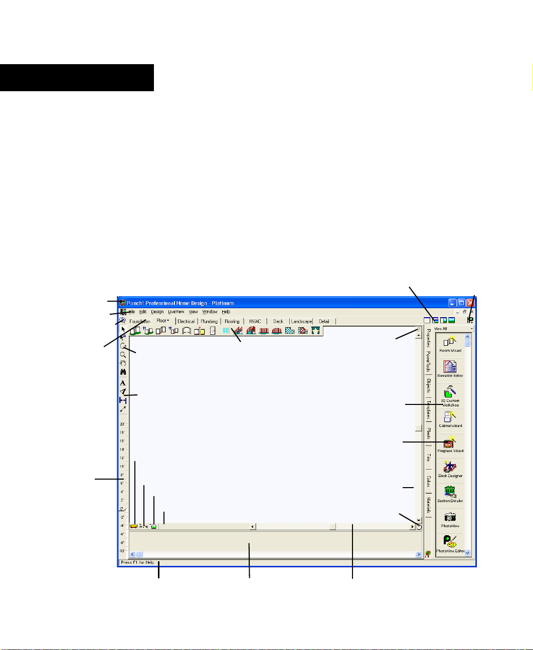
title bar
menu bar
tips & tricks
plan tab
elevation
slider
standard toolbar
annotation and
dimension bar
virtual
ruler
measurement
tools
working floor button
selection filter
plan toolbar
design window
LiveView
icons
context help button
Preview Bar
Properties
Bar
vertical
scroll bar
compass
Launch Punch!
websites
Status Bar
plant inventory bar
PUNCH! Professional Home Design Platinum User’s Guide 5
horizontal scroll bar
Page 10
Chapter A Quick Tour
2
Title Bar
The title bar extends across the top of the application
window. It displays the name of the program and the name of
the current drawing file. Using the buttons at the right end of
the title bar you can minimize, maximize, close or restore the
window. You can also maximize or restore a window by
double-clicking on the title bar. Double-clicking the Control
menu box at the left end of the title bar is a quick way to exit.
If the application is running in a window, rather than
maximized, dragging the title bar moves the entire window
on the desktop.
Menu Bar
You can choose menu items using either the mouse or the
keyboard. To use the mouse, click the menu name; when the
menu drops down, click the item you want. Menu items with
an arrow to the right display cascading menus, when you
place the pointer over one of them. When you highlight a
menu item, a description is displayed on the Status Bar.
To use the keyboard, press the ALT key and type the
underlined letter in the menu name, then type the underlined
letter in the menu item’s name. If there is a cascading menu,
you must type another letter. You can also use the arrow keys
to move through menu items and press ENTER to select one.
The ESC key backs out of the menu items one level at a time.
There are single-key or key combination shortcuts for certain
frequently-used menu items. Each menu lists available
shortcut keys to the right of the item’s name. You can use the
techniques for choosing menu items in combination.
Elevation Slider
With Punch! Platinum’s Elevation Slider you can
easily move selected items vertically off “ground
level”. This feature makes it a snap to make sure
windows, doors, plants, and so on are in exactly the
position you want. Simply select the object or feature
to be raised and move the slider by clicking and
dragging, with the mouse. For more information, see
“Elevating your Selection”, on page 57.
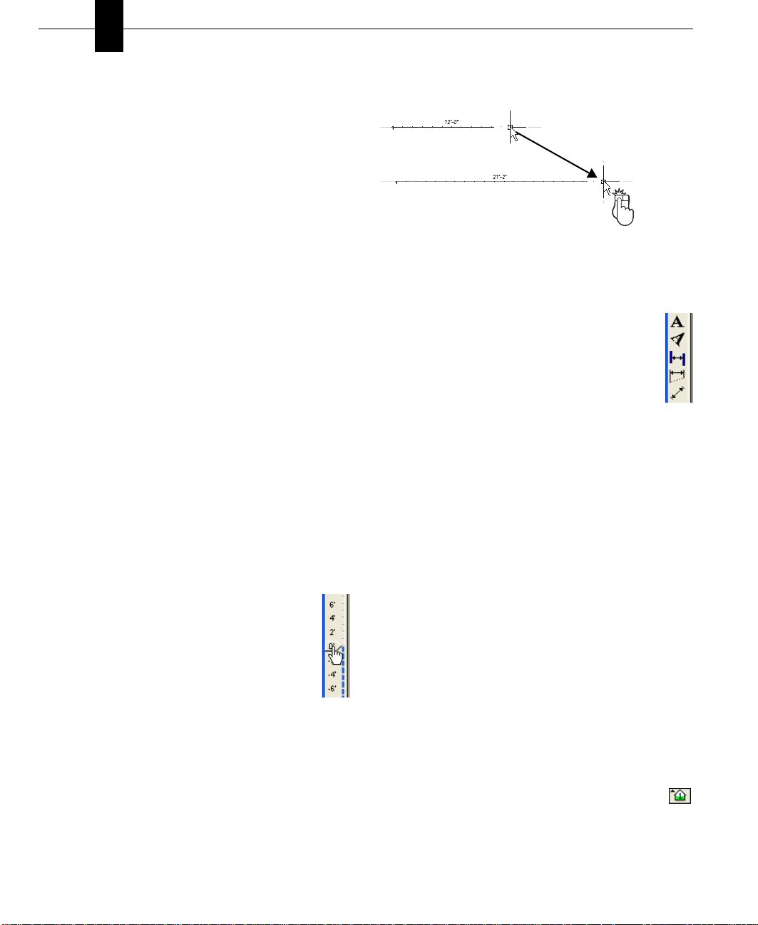
Virtual Ruler
The Virtual Ruler works like a real-world tape measure. It
stores away in the corner of the window, until you need it.
Then, with one click, it is displayed in the middle of the
window, where you can move it into any position necessary
to make a needed measurement. It then stores away until you
need it again. To move the Virtual Ruler, click and drag from
the center. To resize, click and drag on one of the ends, then
drag.
Drag
You are not constrained to vertical or horizontal; the Vertical
Ruler can be stretched in any direction necessary.
Annotation Bar
On the Annotation Bar, there are two tools for text,
straight and angled, and several tools to let you
dimension part of your design where automatic
dimensioning may not be available.
With these tools, you will be able to measure and label
any part of your drawing. If you want, you can store
these labels on the Detail Tab, so you have the option of
turning them off when you want to see your design in a more
unobstructed state.
Measurement Tools
The measurement tools include associative dimensions,
window/door callouts and the shortcuts to calculate floor
square footage.
Associative Dimensioning are the measurements that appear
as you are adding features. For example, the Associative
Dimensioning feature will show how far from the ends of
each wall the window is positioned.
When the Window/Door Callouts option is checked, the
measurements of all window and door openings will be
shown, with the wall measurements, and be displayed in the
floor plan view.
Selecting one of the three square footage options will cause
Punch! Platinum to make that calculation and display it in the
Status Bar.
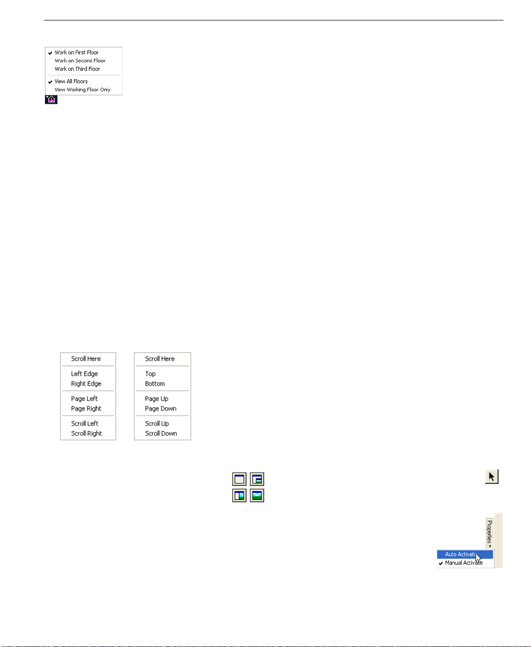
Working Floor Button
Use the Working Floor button to switch the current
view, based on the number of floors in your home plan.
When you click the Working Floor button, a pop-up menu is
displayed. Simply click the floor on which you would like to
work to switch the current working floor.
6 PUNCH! Professional Home Design Platinum User’s Guide
Page 11
Status Bar
Preview Bars
You can click and drag objects, templates, materials, colors,
and so on from their Preview Bars onto your plan. The
Preview Bar changes to reflect your selection. For instance, if
you click the Plant Bar, plant options will be displayed.
Status Bar
The Status Bar is located in the lower left of the window and
displays prompts, program messages, and measurements. It is
a good place to look when you are holding the pointer over
certain buttons or menu items to find their function.
Scroll Bars
Scroll bars provide a way for you to pan across the drawing,
that is, to change the part of the drawing visible in the
window, without changing the level of magnification.
■ To pan the drawing in small increments, click the scroll
arrow that points in the direction you want to pan.
■ To pan in larger increments, click the control shaft,
between the scroll box and a scroll arrow.
■ To pan by a custom increment, drag the scroll box in the
direction you want to pan.
■ To position at a specific area of the page, right-click the
scroll bar and click the wanted area on the pop-up menu
that is displayed.
Clicking one of the buttons on the PowerTool bar launches
one of the associated Punch! Platinum applications. For
example:
■ Launch Topo Designer. To learn more about Topo
Designer, see the chapter titled “Topo Designer”, which
begins on page 71.
■ Launch Material Modifier. To learn more about Material
Modifier, see the chapter titled “Material Modifier”,
which begins on page 207.
■ Launch Roofing Wizard. To learn more about Roofing
Wizard, see the chapter titled “Roofing Wizard”, which
begins on page 133.
All PowerTools launch in this same fashion, whether they
were written by Punch! Software, LLC or by a third-party
developer.
Properties Bar
You can easily modify features you have previously drawn
by selecting them and editing their properties on the
Properties Bar. You can even set the Properties Bar to
automatically display when a feature is selected, by clicking
Auto Activate.
Selecting the Properties Bar
The Properties Bar is easily accessed b y clicking a feature on
your floor plan. For example, clicking a door accesses the
customizable properties for doors and clicking a plant
accesses the properties for plants.
LiveView Icons
It is in the LiveView window where you see your
designs come to life! The default view is Plan Full
View. When you load Punch! Platinum, this is the
view you will see. With the 3D Quarter View option, use
most of your window for drawing, yet be able to view your
design in 3D. For a full explanation see
“Viewing in 2D & 3D”, which begins on page 29.
When you want to focus primarily on your 2D actions, while
maintaining a clear view of the 3D design, select Split Plan/
3D View. Then, when you’re ready to add materials and
colors to your Dream Home it will be easier in the 3D Full
View mode.
the chapter titled
PUNCH! Professional Home Design Platinum User’s Guide 7
To select the Properties Bar
1 On the Standard Toolbar, click the Selection Tool.
2 Click the feature you want to customize. The
Properties Bar is displayed.
Note: If the Properties Bar does not
automatically display, it may be set to
“Manual Activate”. To reset the toggle,
click the arrow after “Properties”, then
click Auto Activate on the pop-up menu
that is displayed.
Page 12
Chapter A Quick Tour
2
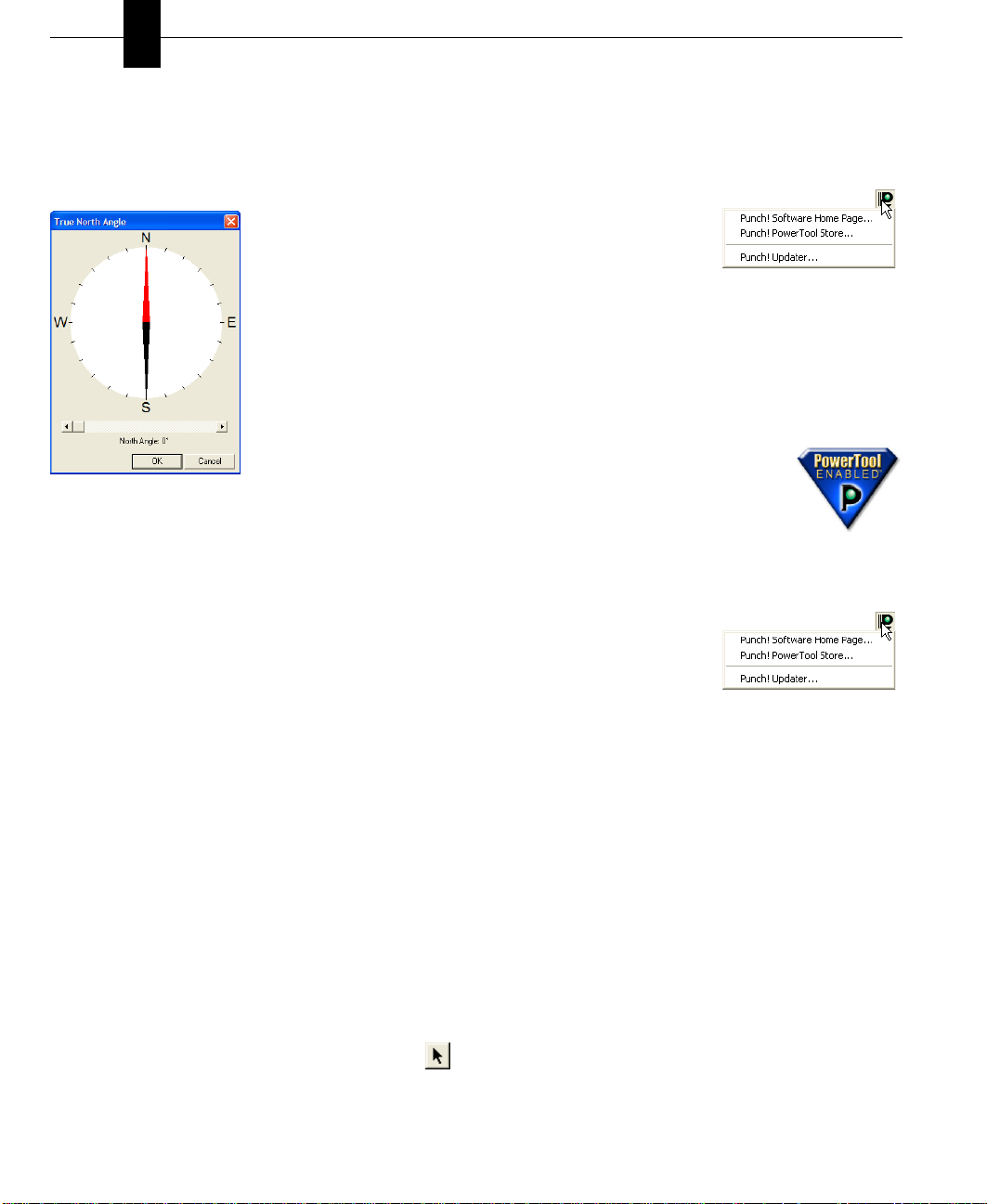
Compass Setting
With the True North compass you can make sure that your
design is placed correctly on your lot. The compass is also
useful to accurately depict the direction of shadows and the
sun’s position.
Plan Tabs
Punch! Platinum utilizes a collection of layers, which are
accessible by clicking the tabs along the top and right side of
the design window. Clicking a plan tab accesses a set of tool s
that you can use to design your floor plan; for example,
clicking the Electrical Tab accesses outlets, switche,s and
ceiling fans, while clicking the Landscaping Tab accesses
tools for edging, fencing, ground fill, excavation, and so on.
Once placed, each feature such as a door, window, plant,
outlet, and so on, can be altered at any time. Click the feature
and the Properties Toolbar is brought to the top (a default that
can be changed) and displays the customizable properties of
that feature.
PunchSoftware.com
With the click of one button, you can visit the Punch! website
at www.punchsoftware.com or the Punch! PowerTool Store
at www.punchsoftware.com/PowerTool_store.htm.
■ To automatically launch your
browser and visit the Punch!
home page, click the Punch!
Software websites button at
the upper right of your
window, then click Punch! Software Home Page.
■ New additions and revisions are being added to the
Punch! content libraries all the time. Use the Punch!
Updater to connect to our server, search for new content
packages, and update your existing content libraries.
Punch! PowerTools™
Punch! Professional Home Design Platinum
is PowerTool enabled. Punch! PowerTools
seamlessly add additional features and
functionality to your program to make it
easier to create your dream home!
Whenever more PowerTools become available, they are
offered to users at the Punch! PowerTool Store.
■ To automatically launch your
browser and visit the Punch!
PowerTool Store, click the
Punch! Software websites
button at the upper right of
your screen, then click Punch! PowerTool Store.
You can further customize which plan layer or combination
of plan layers you want to be active. In addition, you can
make each plan layer a different color, so you can tell at a
glance which layer a specific feature is on. You can even
move features to a different plan, when necessary.
Selecting a Plan Tab
Using the easily-accessible plan tabs, you can quickly access
each tool set at any time.
To select a plan tab
1 On the Standard Toolbar, click the Selection Tool.
2 Click the plan tab you want to use. The plan tab is
selected and the tools available on that tab appear.
8 PUNCH! Professional Home Design Platinum User’s Guide
Page 13

Chapter 3
Finding Answers
Punch! Professional Home Design Platinum is not just one software application, but several applications that can be used
together. Punch! provides you with a number of sources you can use to familiarize yourself with these applications. When
you have questions about a specific feature or procedure, this manual and the Integrated Help system, that you can access
from the program, provide a comprehensive guide to all of the tools in Punch! Professional Home Design Platinum. The
video tutorials that are accessible from the Help menu, on the other hand, are an excellent way to learn about the way real
projects are constructed from the ground up. This chapter also discusses ways to access technical support and the Punch!
website.
PUNCH! Professional Home Design Platinum User’s Guide 9
Page 14
Chapter Finding Answers
3
About This Guide
The text and graphics in this guide are tailored to help you
find the information you need quickly and get the most out of
Punch! Platinum. Each section of this guide is divided into a
series of step-by-step instructions, making it easy for you to
scan a page to find exactly what you need. You can also refer
to the index for additional topics on the same subject, if
necessary.
Instructions for installing and using Microsoft Windows do
not appear in this guide. If you’re uncomfortable with your
knowledge of Windows or with the concepts associated with
a user interface object, you should review Windows online
Help before attempting any serious work with Punch!
Platinum.
Basic Terms
The following is a list of terms used throughout this guide.
Take a moment to familiarize yourself with the language
used in this guide and to reinforce your understanding of
basic terminology.
Click
Pressing and releasing the left mouse button once.
Right-click
Pressing and releasing the right mouse button once.
Double-click
Pressing and releasing the left mouse button twice.
Click and drag
Pressing the left mouse button, holding it down and moving
the mouse, simultaneously.
Drag-and-drop
Clicking to select an item, holding down the mouse button,
then dragging and releasing.
Scroll
Using the scroll bars on the sides of the application window
by clicking the slider box, holding down the mouse button
and dragging.
Graphic Cues
This guide uses several types of graphic elements. Some
show the window or a dialog box that will appear during an
operation. When this type of graphic illustration is used,
every effort is made to show the element exactly as it is
displayed on the window.
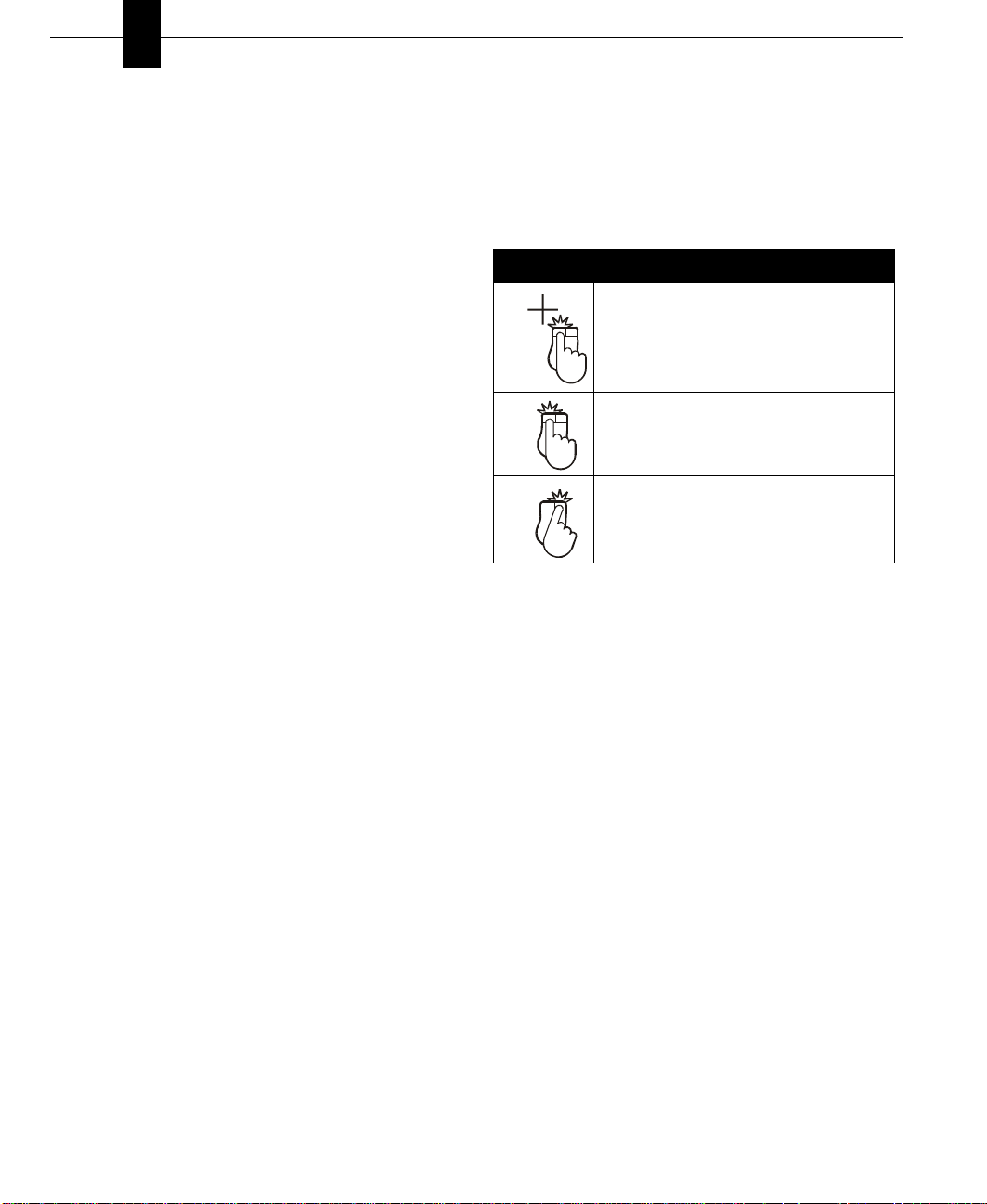
Graphic Cues Used in this Guide
Convention Meaning
mouse click that selects a point—the
number, when present, specifies the mouse
click’s position in a series of clicks
2
click and drag operation—beginning of
arrow indicates where to start; end of arrow
Drag
indicates where to stop
a right mouse click —the number, when
present, specifies the mouse click’s position
in a series of clicks
2
Tips for Users of Other Punch! Programs
Punch! Platinum will open all floor plans designed with
previously-released Punch! programs. One major difference
from very early Punch! programs involves the use of interior,
exterior, and foundation walls. Walls drawn in some previous
Punch! programs, like Punch! Super Home Suite and Punch!
5 in 1 Home Design, may import as interior walls, so these
walls will need to be customized in Punch! Platinum.
In addition, you will want to use the Punch! Topo Designer
PowerTool to update all topography drawn in previouslyreleased Punch! programs.
Designer”, which begins on page 71.
To update a file from a previous Punch! program
1 Make a copy of your file. Save the original.
2 Open the copied file.
3 Define your design’s exterior walls. For more
information, see “To convert exterior walls to interior
walls”, which begins on page 92.
4 Use the Wall Segment Properties dialog box to match all
roof sections. For more information, see “Defining Gable
Wall Segments”, which begins on page 92.
For more information, see “Topo
10 PUNCH! Professional Home Design Platinum User’s Guide
Page 15
Integrated Help
5 Use the Automatic Flooring feature on the upper floors.
For more information, see “To control automatic flooring
for exterior walls”, which begins on page 92.
6 (optional) Draw flooring on the upper floors. For more
information, see “Adding Flooring”, which begins on
page 101.
7 Customize any complex roofing sections. For more
information, see “Using the Freehand Roof Tools”,
which begins on page 124.
Tip: The most important thing to remember when beginning
a new drawing is to complete your foundation or exterior
walls first. A completely-closed exterior perimeter will
ensure that floor square footage measurements will be
correctly calculated.
Integrated Help
Punch! Platinum includes an extensive integrated help
system. This system includes additionl information to that
found in the PUNCH! Professional Home Design Platinum
User’s Guide.
To access the online help files
■ On the Help menu, click Contents or press F1.
To access help for a specific part of your 2D
drawing
1 On the Standard Toolbar, click the Selection Tool.
2 Click the Context Help Button.
3 Click the feature, object, or plant that you want help
with. The Quick Access menu for that feature,
object, or plant is displayed on the right side of the
window.
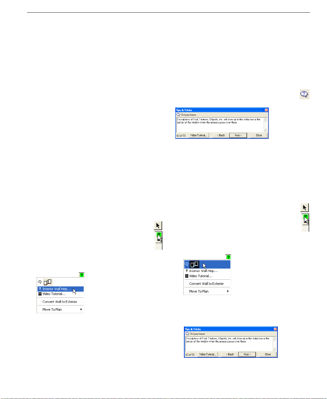
Tips & Tricks
Punch! Platinum makes it easy to get started by providing
users with tips and tricks for each Tool. Tips & Tricks
provide information about each tool and some general
information about the program. Tips & Tricks can be turned
off and on to suit your needs.
To access general tips & tricks
■ On the Standard Toolbar, click the Tips & Tricks
Button.
To access tips & tricks for a specific tool
1 On any plan tab, click the tool you want to learn more
about.
2 Click the Tips & Tricks Button; the Tips and Tricks
menu for that tool is displayed.
To access tips & tricks for a part of your 2D drawing
1 On the Standard Toolbar, click the Selection Tool.
2 Click the Context Help Button.
3 Click the feature, object, or plant that you want help
with. The Quick Access menu for that feature,
object, or plant is displayed on the right side of the
window.
4 Click the tool’s Help listing on the pop-up window. Help
for that feature, object, or plant is displayed.
5 (optional) Pressing F1, while many tools are active, will
access the help file for that Tool.
PUNCH! Professional Home Design Platinum User’s Guide 11
4 Click the Tips & Tricks listing at the top of the pop-up
window. The Tips & Tricks menu for that feature, object,
or plant is displayed.
5 (optional) Click Back or Next to cycle through the tips
available for that feature, object, or plant.
Page 16
Chapter Finding Answers
3
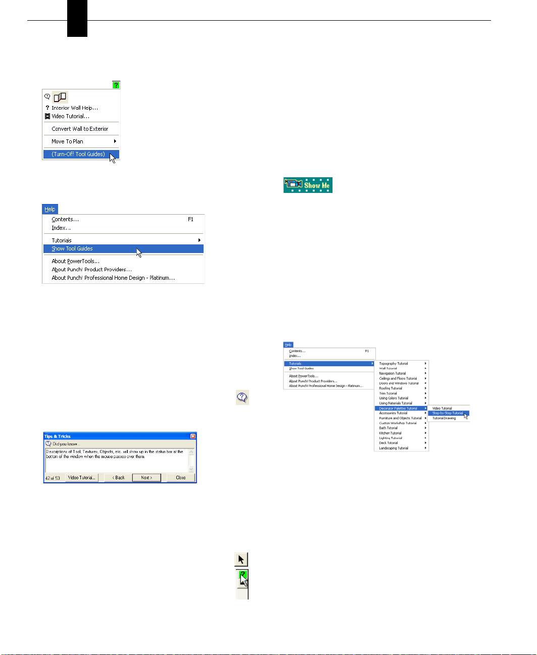
To turn tool guides on and off
■ To turn off Tool Guides, click (Turn-Off Tool Guides).
■ To turn on Tool Guides, on the Help Menu, click Show
Tool Guides.
Video Tool Tip Tutorials
Video Tutorials are available for drawing tools and other
commonly-used features. These tutorials can be accessed
three ways.
3 Right-click the feature, object, or plant that you want
help with. The Quick Access menu for that tool, object,
or plant is displayed.
4 Click Video Tutorial on the pop-up window. A short
video will be played, showing how the tool works.
To access tool tip tutorials from Help
1 On the Help menu, click Contents or press F1.
2 Navigate through the Help System, until the topic you
need is displayed.
3 Click the Show Me button. A short video will be played,
showing how the tool or feature works.
Video Step-by-Step Tutorials
You can get started easily with Punch! Platinum’s Step-byStep Tutorials. They are available at all times , from the Help
Menu.
To access the step-by-step tutorials
1 On the Help Menu, click Tutorials. A listing of available
tutorials is displayed.
To access tool tip tutorials from Tool Guides
1 On the Standard Toolbar, click the Selection Tool.
2 Click the feature, object, or plant that you want help
with, then click the Tool Guide Tool. The Tips and
Tricks menu for that tool is displayed.
2 Hightlight the topic you want to view, then click how you
want to view the tutorial.
3 Click the Video Tutorial button on the Tips and Tricks
menu. A short video will be played, showing how the
tool works.
To access tool tip tutorials with a right-click
1 On the Standard Toolbar, click the Selection Tool.
2 Click the Context Help Button.
■ Video Tutorial: Shows a short video movie of the topic.
■ Step-by-Step Tutorial: Displays an HTML file that
follows along with the Video Tutorial.
■ Tutorial Drawing: Opens the Punch! Platinum file used
in the selected Video Tutorial.
Technical Support
Before contacting Punch! Technical Support, please verify
that the answer to your question is not available from one of
the following resources:
12 PUNCH! Professional Home Design Platinum User’s Guide
Page 17

■ Punch! Professional Home Design Platinum User’s
Guide
■ Punch! Platinum Help System
■ Video Tutorials
■ To automatically launch your browser and visit the
Punch! Software website, click the Connect to
Punch! button at the upper right of your window.
■ The Punch! Online Community is available at
http://forums.punchsoftware.com. At the Online
Community, users can post questions and trade useful
tips and tricks.
■ The Customer Support Center is available at
http://punch.custhelp.com. At the Customer Support
Center you can register your software, search the
knowledge base, or ask a question, if necessary.
The Customer Support Center can only answer questions that
are related to features of Punch! Professional Home Design
Platinum. They cannot answer specific questions about home
building, local building codes, and so on.
When contacting the Support Center, please provide the
following details:
■ Serial Number - located on the Help > About Punch!
Home Design dialog box
■ Your computer’s operating system
■ Make and model of your computer
■ Video card manufacturer and model
■ Video card driver date and version
■ Video RAM
■ Display settings, including hardware acceleration
Technical Support
After registering your program, you will receive 60 days of
free technical support. When you call, you should be in front
of your computer, with the program running, and have the
above information handy. The technical support contact
information can be located at the Customer Support Center http://punch.custhelp.com.
PUNCH! Professional Home Design Platinum User’s Guide 13
Page 18

Chapter Finding Answers
3
14 PUNCH! Professional Home Design Platinum User’s Guide
Page 19

Chapter 4
Before You Draw
To get the most benefit from Punch! Professional Home Design Platinum, you should take a minute to become familiar
with some of its basic concepts. This chapter describes a few settings you should know before you begin your project.
With Punch! Platinum you can set a precise drawing scale, define units of measurement and set the reference grid. There
are also many performance settings you can apply to optimize drawing speed and 3D viewing.
PUNCH! Professional Home Design Platinum User’s Guide 15
Page 20
Chapter Before You Draw
4
Important System Settings
Some of your computer’s settings can impact Punch!
Platinum’s efficiency. By changing one (or more) of these
settings, you can control how the program performs.
■ Set your Display Settings to 800x600 pixels and High
Color (24-bit) or True Color (32-bit). On your Start
menu, select Control Panel>Display>Settings.
■ If you notice that the 3D display is not clear, reduce the
Graphics Acceleration. On your Start menu, select
Control Panels> System>Performance>Graphics, then
set the acceleration back one notch.
■ By default, all measurements display in English Units; to
choose Metric Units go to Design>Unit of Measure...
select Metric Units.
Speed Tips
You can “Speed Up” Punch! Platinum by changing some of
the program's settings.
■ Close the LiveView window when you are not working
in 3D. No 3D calculations are performed when the
LiveView window is closed.
■ Choose the Quarter-View window size for LiveView
instead of Full-View to increase 3D rendering speed.
■ Turn off shadows. For more information, see “Adding
Lighting and Shadows”, which begins on page 38.
■ Hide floors that are not active. Turning off inactive
floors, means the program will not waste resources on
them.
■ On the View menu, click Render Options. The Render
Options dialog box is displayed. The lower the render
quality, the faster LiveView will render your design.
5 In the Screen Area section, move the slider to display at
least 800 x 600 pixels.
6 Click OK. The new window settings are applied. You
may be prompted to restart your computer to apply the
new settings. If so, click OK or Yes.
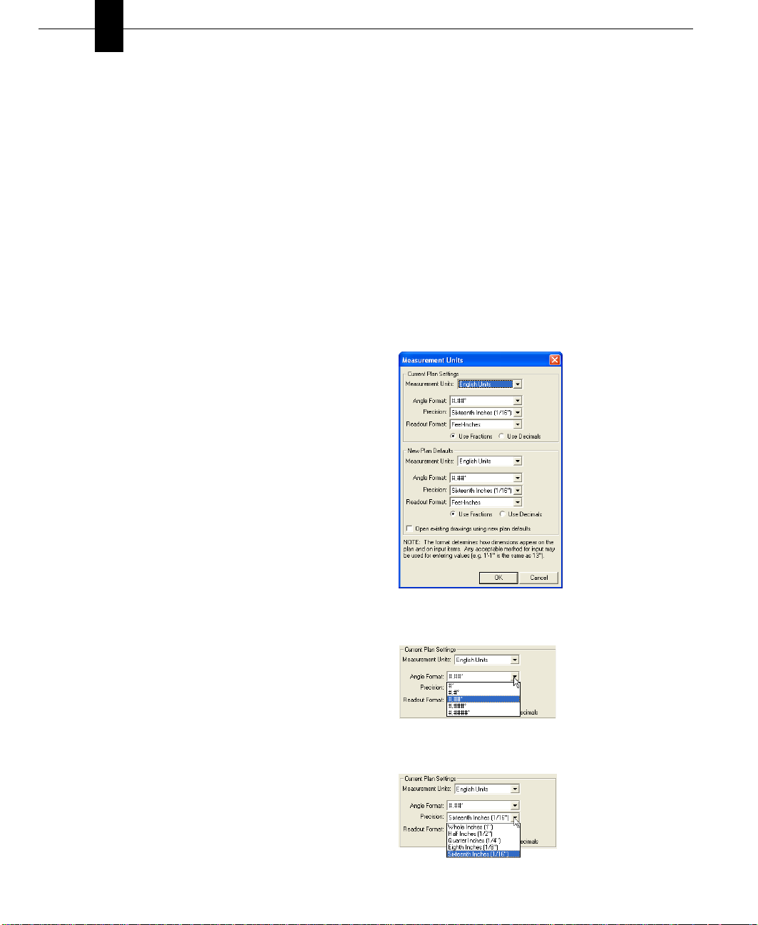
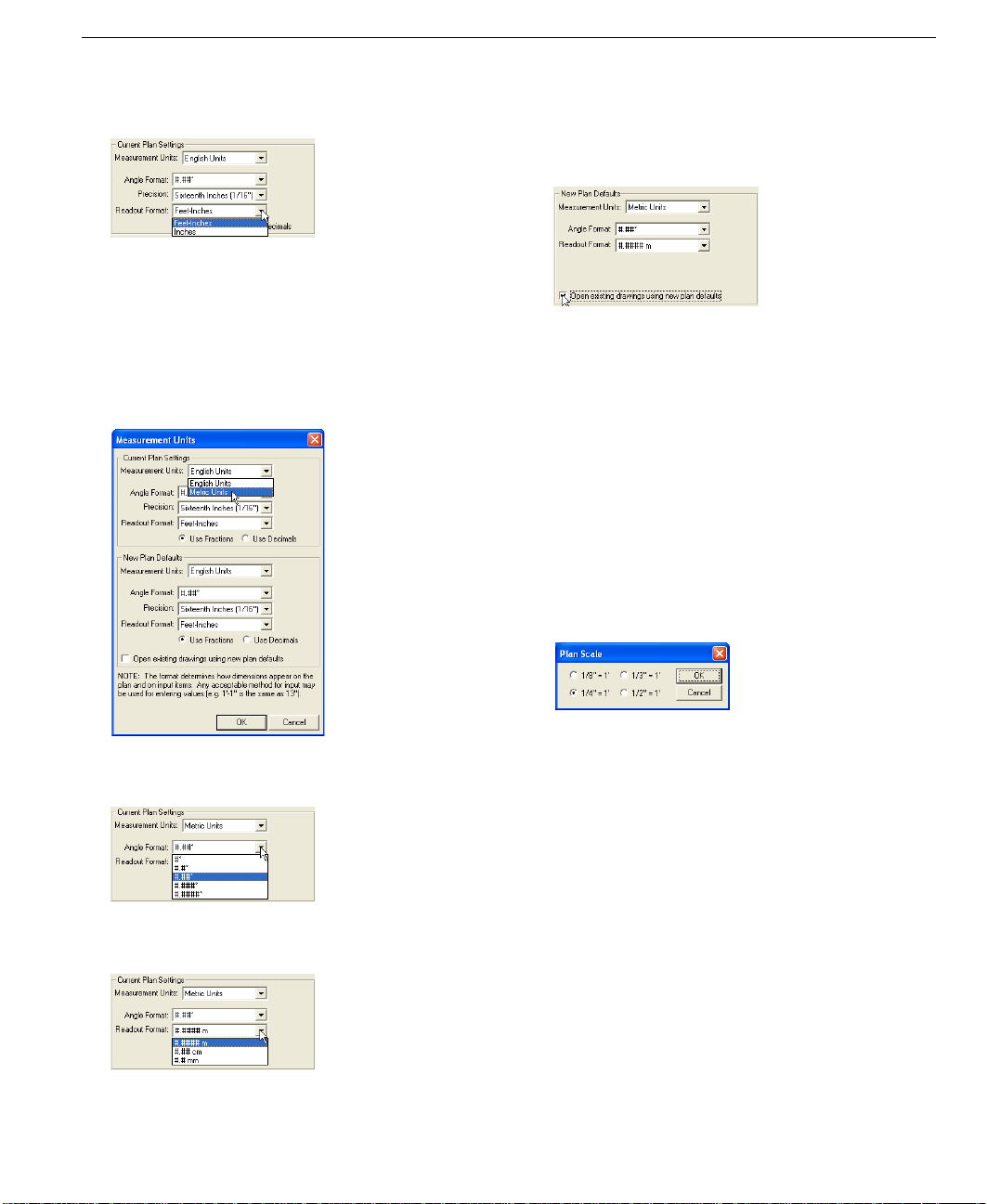
Setting the Units of Measurement
You can set units of measurement by selecting either English
or Metric measurements. You can also set the default
measurements and options to be applied when any
previously-drawn design is opened.
To use English measurements
1 On the Design menu, click Unit of Measure. The
Measurement Units dialog box is displayed.
2 Click English Units.
Display Settings
Punch! Platinum is designed to run effectively, based on the
3 (optional) Click the arrow next to Angle Format and
select the number of decimal points you want to use.
system requirements printed on the software packaging.
However, there are some specific settings you can select to
obtain the best display possible.
To adjust your display settings
1 On the Start menu, click Settings, Control Panel. The
Control Panel program group is displayed.
4 (optional) Click the arrow next to Precision and select the
number of decimal points you want to use.
2 Double-click Display. The Display Properties dialog box
is displayed.
3 Click the Settings page tab.
4 In the Colors list box, click True Color (32-bit).
Note: If 32-bit is unavailable, click True Color (24-bit).
16 PUNCH! Professional Home Design Platinum User’s Guide
Page 21
Setting the Scale
5 (optional) Click the arrow next to Readout Format and
select the format you want.
6 Click OK. The unit of measurement and options you
selected are applied.
To use Metric measurements
1 On the Design menu, click Unit of Measure. The
Measurement Units dialog box is displayed.
2 Click Metric Units.
To set defaults for previous designs
1 Follow the instructions for either English or Metric units,
outlined above, then click the box to set the defaults for
all previously-drawn designs.
2 Click OK. The defaults will be applied to any previously-
drawn design when it is opened.
Setting the Scale
Scale is the ratio between real-world size of objects and items
in your drawing and their size when printed. The default
drawing scale is 1/4" = 1', meaning that 1/4" on your drawing
plan equals one foot in real-world size. You can customize
scale settings at any time to suit your needs, as well as print
your drawing to scale.
To set the drawing scale
1 On the Design menu, click Plan Scale. The Plan Scale
dialog box is displayed.
3 (optional) Click the arrow next to Angle Format and
select the number of decimal points you want to use.
4 (optional) Click the arrow next to Readout Format and
select the format you want.
5 Click OK. The unit of measurement and options you
selected are applied.
PUNCH! Professional Home Design Platinum User’s Guide 17
2 Click a new scale setting, then click OK. The new scale is
applied to your plan drawing.
Defining Your Lot Size and Topography
Use the Site Planner and Topo Designer PowerTools to
define lot size and all topography.
Note: After you’ve created topographical objects using
Topo Designer, the Design, Lot Size option on the Menu Bar
is disabled. All further changes to the lot size need to be
made using Topo Designer.
For more information, see “Topo Designer”, which begins on
page 71.
Note: To draw curved property lines, use the Curve Tool on
the Detail Tab, then
Features”, which begins on page 165.
see “Converting Details to Intelligent
Page 22

Chapter Before You Draw
4
18 PUNCH! Professional Home Design Platinum User’s Guide
Page 23

Part 2
Punch! Software Primer
Chapter 5: Drawing 2D Entities . . . . . . . . . . . . . . . . . . . . . . 21
Chapter 6: Viewing in 2D & 3D . . . . . . . . . . . . . . . . . . . . . . 29
Chapter 7: Adding 3D Features . . . . . . . . . . . . . . . . . . . . . . 45
Chapter 8: Rearranging Entities . . . . . . . . . . . . . . . . . . . . . . 55
Chapter 9: Managing Content . . . . . . . . . . . . . . . . . . . . . . . . 61
Chapter 10: Saving, Sharing, & Printing . . . . . . . . . . . . . . . 65
Page 24

Page 25

Chapter 5
Drawing 2D Entities
This chapter contains concepts and procedures that you will need throughout your design process.
Many 2D features are drawn the same way throughout Punch! Professional Home Design Platinum and the PowerTools
that are included with it. Whether you are drawing a rectangle to mask part of a tree in Plant Editor or a rectangle to tint a
custom material in Material Modifier, it will always be drawn in the same way. The icons may differ slightly, but the
process is the same.
PUNCH! Professional Home Design Platinum User’s Guide 21
Page 26
Chapter Drawing 2D Entities
5
Drawing Shapes
Many features are drawn the same way throughout Punch!
Professional Home Design Platinum and the PowerTools that
are a part of it. Whether you are drawing a rectangle to mask
part of a tree in PlantEditor or a rectangle to tint a custom
material in Material Modifier, it will always be drawn in the
same way. The icons may differ slightly, but the process is
the same.
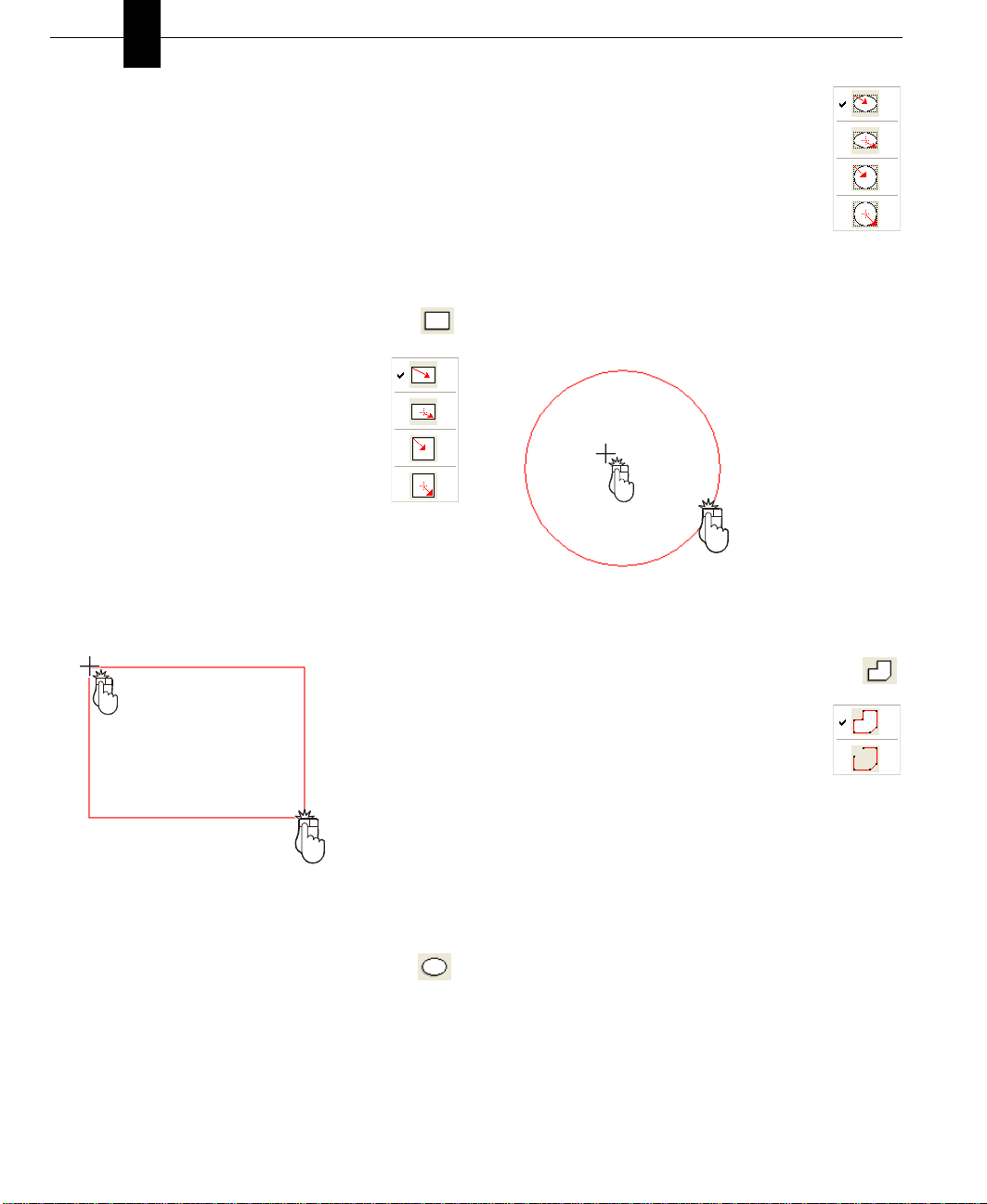
To draw rectangles and squares
1 Click the Rectangle Tool. The pointer changes to
reflect drawing mode.
2 (optional) On the Properties Bar, click the
Method button and choose how you want to
draw the shape:
■ Rectangle from the corner,
■ Rectangle from the center,
■ Square from the corner,
■ Square from the center.
3 Click on the design window to define the
start point of the rectangle. A rubber-band rectangle is
displayed and follows the pointer. Dimensions are
displayed, as you draw.
4 Hold the mouse button down, as you extend the rectangle
to the size you want.
2
1
Drag
5 Release the mouse button.
To draw circles and ovals
1 Click the Circle/Oval Tool. The pointer changes to
reflect drawing mode.
2 (optional) On the Properties Bar, click the
Method button and choose how you want to
draw your shape:
■ Oval from the edge,
■ Oval from the center,
■ Circle from the edge,
■ Circle from the center.
3 Click on the design window to define the start point of
the shape. A rubber-band shape is displayed and follows
the pointer. Dimensions are displayed, as you draw.
4 Hold the mouse button down, as you extend the shape to
the size you want.
2
1
Drag
5 Release the mouse button.
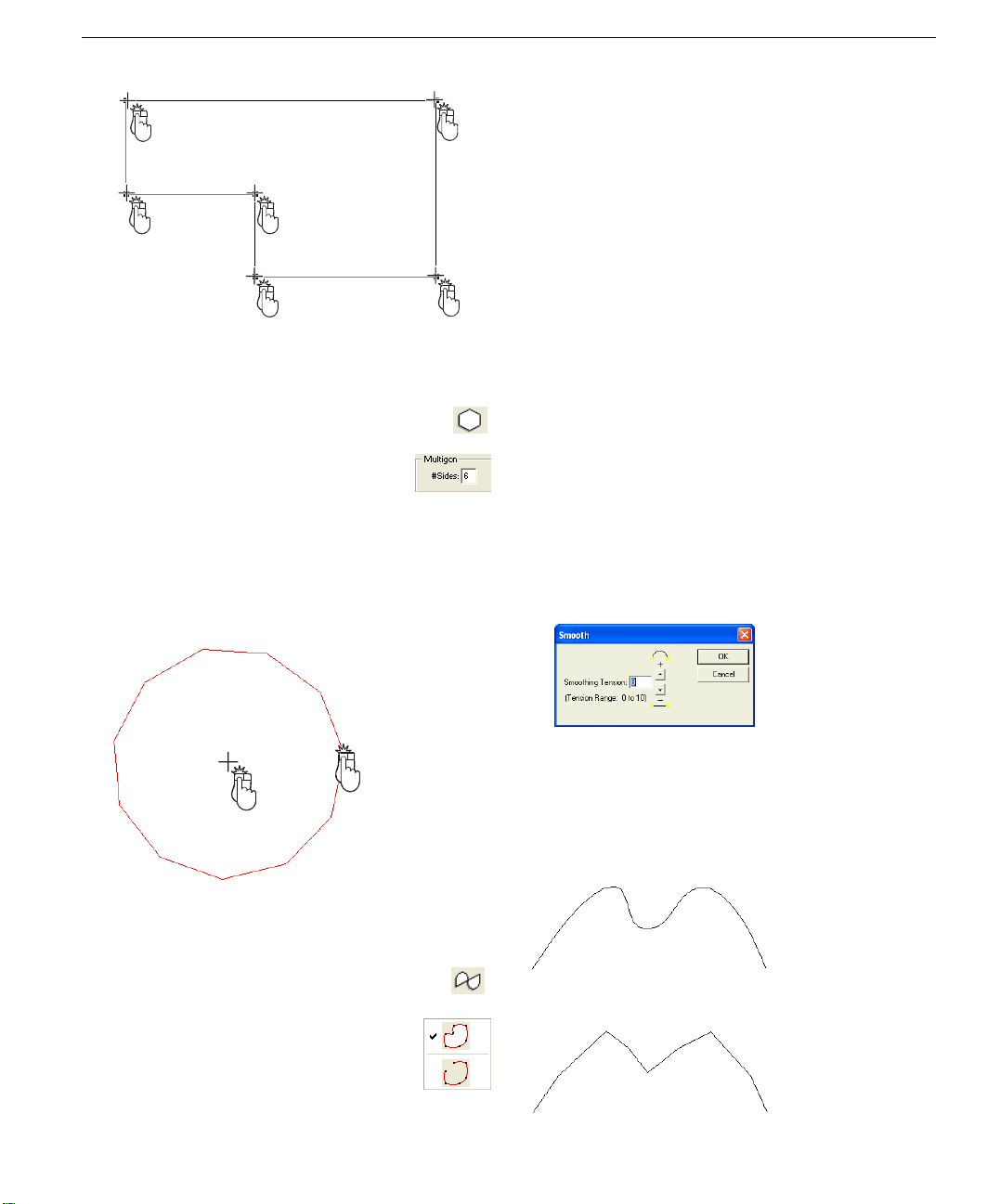
To draw a polygon
1 Click the Polygon Tool. The pointer changes to
reflect drawing mode.
2 (optional) On the Properties Bar, click the
Method button and choose how you want to
draw the shape:
■ Closed polygon,
■ Open polygon.
3 Click on the design window to define the start point of
the polygon. A rubber-band line is displayed and follows
the pointer. Dimensions are displayed, as you draw.
4 Click and move the mouse to the next cornerpoint.
Repeat until you have drawn the necessary shape.
22 PUNCH! Professional Home Design Platinum User’s Guide
Page 27
Changing Curve Tension
3 Click on the design window to define the start point of
the curve. A rubber-band curve is displayed and follows
2
2
1
the pointer.
4 Click and move the mouse to the next point. Repeat until
you have drawn the needed shape.
2
5
2
4
Note: Although the lines will initially appear angular, they
will become curved when you end drawing mode.
5 Double-click to end drawing mode.
2
3
2
2
5 Right-click to end drawing mode.
To draw a multigon
1 Click the Multigon Tool. The pointer changes to
reflect drawing mode.
2 (optional) On the Properties Bar, type the
number of sides you want the multigon to
have.
3 Click on the design window to define the start point of
the multigon. A rubber-band multigon is displayed and
follows the pointer.
4 Hold the mouse button down, as you extend the multigon
to the size you want.
Drag
2
1
Changing Curve Tension
To further control the look of the shapes drawn with any of
the arc or curve tools, you have control over the degree of
curve assigned to them. With the Str aighten fea ture, it is easy
to create angular shapes and, with Curve Tension, you can
change the appearance. Curve Tension is measured between
1 and 10. Specifying 1 in the dialog box results in very little
tension being applied, while specifying 10 causes a slightlyexaggerated curve.
To change curve tension
1 Click an object to select it.
2 On the Properties Bar, click Adjust, in the Curve section.
The Smooth dialog box is displayed.
3 Type the amount of tension that you want.
4 Click OK. The Curve Tension you specified is applied.
Examples:
5 Release the mouse button.
To draw a curve
1 Click the Curve Tool. The pointer changes to
reflect drawing mode.
2 (optional) On the Properties Bar, click the
Method button and choose how you want to
draw the shape:
■ Closed Curve,
■ Open Curve.
Default Curve Tension (8):
Curve Tension set at 2:
PUNCH! Professional Home Design Platinum User’s Guide 23
Page 28
Chapter Drawing 2D Entities
5
To remove curve tension
1 Click an object to select it.
2 On the Properties Bar, click Straighten, in the Curve
section. The curve is changed to a polyline.
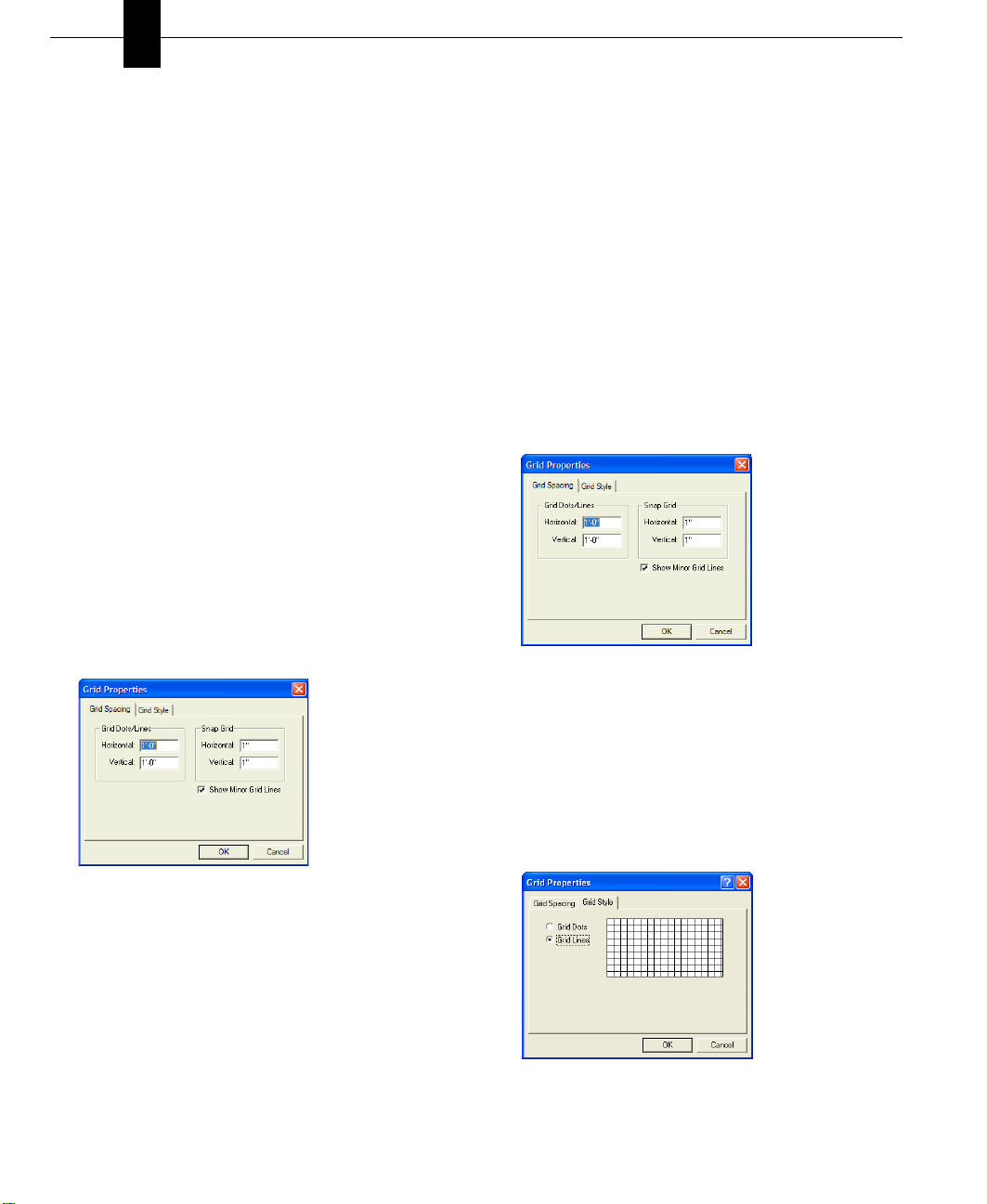
Using the Grid
With Punch! Platinum you can set specific grid properties
that aid in drawing your home plan. You can set points, based
on the reference grid, which is useful when you want to make
sure certain points are specified precisely.
Grid settings have a direct impact on the ease of aligning
objects, snapping objects to the grid, and so on. When using
the Snap to Grid feature, items that are dragged and dropped
on the design window are automatically snapped, or placed,
to align with the current grid. By default, Snap to Grid is on.
You can customize grid settings by selecting grid spacing,
grid style, and hiding or displaying.
Grid properties can also be set by accessing the right-cl ick
menu, with nothing selected.
To define Snap to Grid settings
1 On the View menu, click Grid Properties or right-click
on your design window and click Grid Properties on the
pop-up menu that is displayed. The Grid Properties
dialog box is displayed.
Note: Initially, the grid is set at 12 i nches, m aking it easy to
visualize each plan square as exactly one square foot, but can
be customized to meet your particular design needs.
Note: Snap settings can be set as low as 0.0625 (1/16) inch
(English), 0.01 meter (1 cm) (Metric), and still show visible
movement along the grid. Snap settings can be set as high as
500 inches (English), 12.70 meter (Metric).
To select grid spacing
1 On the View menu, click Grid Properties or right-click
on your design window and click Grid Properties on the
pop-up menu that is displayed. The Grid Properties
dialog box is displayed.
2 Type new horizontal and vertical measurements in the
Grid Dots/Lines section of the Grid Spacing page, then
click OK. The new grid spacing is applied.
To change the grid style
1 On the View menu, click Grid Properties or right-click
on your design window and click Grid Properties on the
pop-up menu that is displayed. The Grid Properties
dialog box is displayed.
2 Click the Grid Style page tab.
3 Click either Grid Dots or Grid Lines, then click OK. The
new grid style is applied.
2 On the Grid Properties dialog box, type new
measurements in the Snap Grid text boxes, then click
OK. Items you draw or drag-and-drop into the design
window will now snap to the measurements you’ve
defined.
3 (optional) When you change the Snap Grid settings,
Minor Grid Lines are displayed to show where along the
grid you are snapping. To turn off the display of Minor
Grid Lines, click to uncheck the Show Minor Grid Lines
checkbox.
24 PUNCH! Professional Home Design Platinum User’s Guide
Page 29
Dimensioning
Note: Grid Dots/Lines can be set to as low as 1 inch
(English), 0.02 m (Metric), and still be viewable. Grid Dots/
Lines can be set as high as 500 inches (English), 12.70 m
(Metric).
To move objects/features along the grid
1 On the Standard Toolbar, click the Selection Tool.
2 Click the object or feature you want to move.
3 Using the arrow keys on your keyboard, move the object
or feature into position.
Note: Each time you press an arrow key, the object or
feature will move one increment that you hav e set in the Snap
Grid settings.
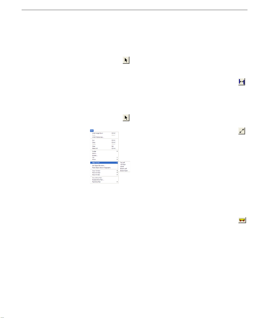
To align objects/features with an area of the grid
1 On the Standard Toolbar, click the Selection Tool.
2 Click the object or feature you want to align.
3 On the Edit menu, click Align to
Grid, then click with which area
of the grid you want your
selection aligned.
generated. Dimensions drawn with the Dimension Wall tool
are automatically updated when either wall is moved. You’ll
find this tool extremely useful when measuring between the
main house and the walls of other buildings, like a garden
shed or playhouse. In some instances, you might want to print
your plan drawing without dimension annotation. You have
the option of turning off automatic dimensioning, if you
don’t want it displayed on the drawing page or as you draw.
To use the wall-spacing dimension tool
1 On the Annotation toolbar, click the Dimension
Wall Tool.
2 Click a wall on the design window to define the starting
point; hold down the mouse button and drag to the
second wall.
3 Release the mouse button to set the measurement.
To use the zero-offset dimension tool
1 On the Annotation toolbar, click the Zero-Offset
Dimension Tool.
2 Click on the design window to define the starting point;
hold down the mouse button and drag to the ending point
of the measurement you require.
3 Release the mouse button to set the measurement.
To turn off Snap to Grid
■ On the View menu, click to uncheck Snap to Grid, press
CTRL+R, or right-click on your design window and click
Snap to Grid on the pop-up menu. The feature is
disabled. To enable Snap to Grid, simply recheck the
menu item.
To display the grid
■ On the View menu, click to check Grid Visible or right-
click on your design window and click Grid Visible on
the pop-up menu that is displayed. The grid is displayed
on the design window.
Dimensioning
Punch! Platinum automatically displays dimensions, as you
draw, making it easy to precisely place walls, doors, and
other items in your plan drawing. The powerful Dimension
Wall tool will be especially useful to add interactive
dimensions between walls, where they are not automatic al ly
PUNCH! Professional Home Design Platinum User’s Guide 25
Using the Virtual Ruler
The Virtual Ruler is a handy feature for measuring items in
your home plan that are not automatically dimensioned. You
can “undock” the ruler at any time, leaving it active, or hide it
from view with one mouse click. The Virtual Ruler is an easy
way to measure at an angle, too.
To measure using the Virtual Ruler
1 Click the Virtual Ruler button at the bottom of the
design window, or right-click on a blank area of
the drawing space and click Center Virtual Ruler, on the
pop-up menu. The Virtual Ruler is displayed on the
drawing page.
2 Click an end and drag in the direction you want to
measure. The measurement is displayed in the center of
the Virtual Ruler.
3 (optional) Click the center of the Virtual Ruler and drag it
to a new location on the design window.
Tip: Zoom in on the area you are measuring so you have a
close-up view of the ruler.
Page 30
Chapter Drawing 2D Entities
5
To hide the Virtual Ruler
■ Click the Virtual Ruler button at the bottom of the
design window, or right-click on the ruler and
click Hide Virtual Ruler, on the pop-up menu. The
Virtual Ruler is “docked.”
Calculating Square Footage
Punch! Platinum can automatically calculate square fo otage
of each floor of your home plan. This feature makes it easy to
figure how much carpet you’ll need to cover the first floor,
for instance, or simply estimate your overall home size. If
square footage is incorrect, check to make sure the exterior
perimeter is intact.
Foundation Perimeter”, which begins on page 84.
To calculate floor square footage
■ At the bottom of the window, click the Dimension
button, then click First Floor Square Footage (or
Second or Third floor). Punch! Platinum calculates the
square footage and the total is displayed on the Status
Bar.
Note: The square footage calculation is based on wall
centerline measurements.
For more information, see “Defining the
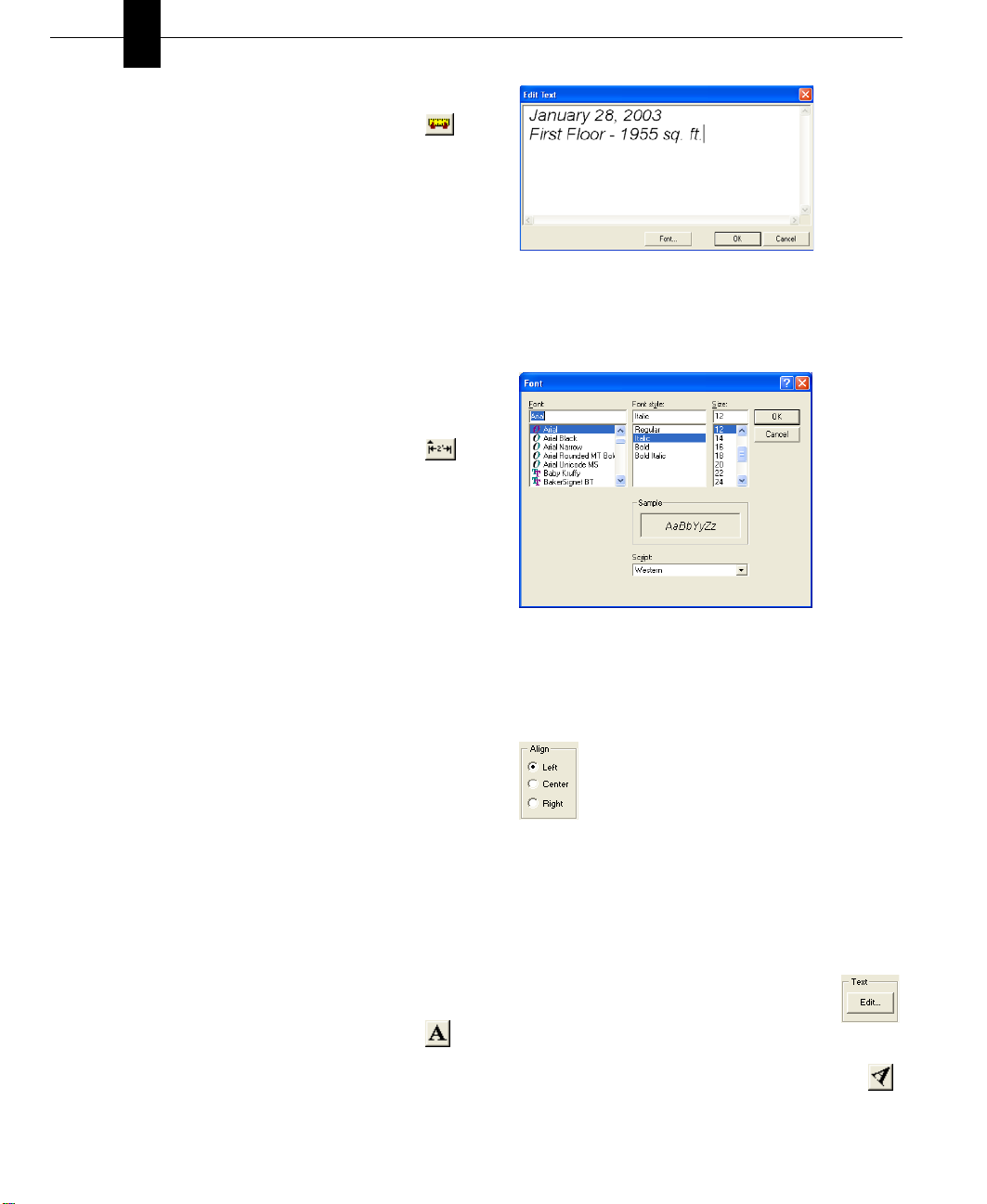
3 Type the annotation in the text box. Click OK to end edit
mode.
4 (optional) Click Font; the Font dialog box is displayed.
Choose the Font, Style and Size, then click OK.
Adding Text
Use text to add information to your drawing. For example,
you might add text to annotate rooms, specify a home
address, the date the drawing was created, or a specific
feature in your plan. Punch! Platinum gives you the
flexibility to place text anywhere in your plan drawing, using
different formatting techniques for each text instance. Text
you place in your drawing is displayed on all 2D printed
output.
To set font before adding text
1 On the Design menu, click Text Font. The Font dialog
box is displayed.
2 Set the font as you want it to be applied to all subsequent
text.
3 Click OK.
To place text in your drawing
1 On the Annotation toolbar, click the Multi-Line
Text Tool.
2 Click the area where you want to place text on the
drawing page. An Edit Text dialog box is displayed.
To change alignment of multi-line text
1 Using the Selection Tool, click the text you want to
change. Selection handles appear around the text.
2 Click Center on the Properties Bar.
3 (optional) Click Right on the Properties Bar.
To edit text
■ Double-click the text you want to edit.
OR
■ Click the text you want to edit, then click Edit
on the Properties Bar.
To place text at an angle
1 On the Annotation Toolbar, click the Rotated Text
Tool.
26 PUNCH! Professional Home Design Platinum User’s Guide
Page 31

2 Click the area where you want to place text on the
drawing page. An Edit Text dialog box is displayed.
3 Type the annotation in the text box.
4 Click the radio button next to the angle you want or enter
a custom angle in the dialog box.
5 Click OK to end edit mode.
6 (optional) Click Font; the Font dialog box is displayed.
Choose the Font, Style and Size, then click OK.
To change formatting of existing text
1 Using the Selection Tool, click the text you want to
change. Selection handles appear around the text.
2 On the Properties Bar, click Edit or double-click the
selected text. The Font dialog box is displayed.
3 To change the text font, click a new font on the Font list.
4 To change the text style, click a new style on the Font
style list.
5 To change the text size, click a new size on the Size list.
6 Click OK.
Adding Text
PUNCH! Professional Home Design Platinum User’s Guide 27
Page 32

Chapter Drawing 2D Entities
5
28 PUNCH! Professional Home Design Platinum User’s Guide
Page 33

Chapter 6
Viewing in 2D & 3D
Punch! Platinum provides many options for looking at your design onscreen. You can display several windows, each
containing a different view of your plan. This gives you the flexibility to view your drawing as a 2D plan, as a 2D plan with
a corresponding 3D view or using only Punch! LiveView.
When viewing your 2D home plan, you can magnify the view by zooming in, reduce the view by zooming out, use the
Viewpoint tool to display a specific area of your drawing or pan the view in any direction.
3D viewing provides many options, from walking through the home plan to flying around the plan or viewing the framing
or completion phase of your project. You can adjust 3D display settings using a variety of viewing features, including
adding shadows, for a realistic effect, or adjusting the lighting intensity of the view. Finally, you can create a photorealistic view of your design.
In this chapter, you’ll learn about the numerous commands designed to let you view your design in both 2D and 3D.
PUNCH! Professional Home Design Platinum User’s Guide 29
Page 34

Chapter Viewing in 2D & 3D
6
Viewing the 2D Plan
When initially designing your plan, you will probably want
to view the 2D plan view only. Once completed, you can
view your plan in a combination of 2D and 3D or in 3D only.
In addition, Punch! Platinum organizes your floor plan into
layers, which are each easily accessible with a si ngle mouse
click. For example, you can choose to view the deck plan
with landscaping one moment, then quickly switch to view
electrical and plumbing. Any combination ... any time!
To view the 2D plan only
■ On the Window menu, click Plan Full View. The 2D plan
view is displayed.
To view all 2D floor plan views at once
■ Click the Working Floor button at the left bottom
of the design window, then click to check View
All Floors.
To view the working floor only
■ Click the Working Floor button at the left bottom
of the design window, then click to check View
Working Floor Only.
To view drawing layer combinations
1 Click a plan tab.
2 Click the arrow to the right of the tab
label. A drop-down menu will appear.
3 Click the plan you want to view.
4 (optional) Repeat until the
combination you want is reached.
3 Click on the design window and drag in a downward
direction to zoom out.
Note: When the mouse is clicked, the location of the cursor
will be centered on the design window.
To zoom in using the wheel mouse
■ Click on the design window and use the mouse’s wheel
to zoom in and out.
Note: To access this feature, using some older wheel mouse
drivers, set the Scrolling Size to “None” in the Control
Panel>Mouse>Mouse Properties>Buttons dialog box.
To set the zoom factor
1 Double-click the Zoom tool or on the View menu, click
Set Plan View Zoom. The Set Plan View Zoom dialog
box is displayed.
2 Type a new zoom factor, then click OK.
To reset the 2D plan view
■ On the View menu, click Reset Plan View or press
CTRL+E on your keyboard. Your plan is reset to the
original, default view.
Panning Across the 2D Drawing
You can move the design window to see portions of the plan
which are outside the current view, by panning. Panning also
makes it easy to slowly view areas of your drawing piece-bypiece.
Zooming In and Out in 2D
You can get a closer look at an area or see a larger portion of
your plan drawing by zooming in and out. By dragging over
the drawing, the view enlarges or decreases dynamically.
You can also set the zoom factor to obtain exact zoom
precision. Once you’ve finished viewing your plan close-up,
you can return to the previous, full view with one mouse
click.
To zoom in
1 On the Standard Toolbar, click the Zoom button.
2 Click on the design window and drag in an upward
direction to zoom in.
30 PUNCH! Professional Home Design Platinum User’s Guide
To pan in any direction
1 On the Standard Toolbar, click the Pan button. The
pointer changes to reflect Pan mode.
2 Click on the design window and drag in the direction you
want to view. The view changes, dynamically, as you
move the mouse.
Fitting Your Design to Your Current Window Size
You can quickly position your entire deisng within your
window, without using the Pan Tool or Zoom Tool.
Page 35

To fit your entire design within your window
■ Press CTRL+F or, on the View menu, click Fit to
Window.
Customizing Visible Plans
During the design of your floor plan, there may be times
when you want certain layers, that by default are hidden, to
be visible. For example, while working on your electrical
plan, you may need to see where plumbing lines will be.
Punch! Platinum makes it easy to customize how you view
your plan layers.
You can also assign custom colors to areas of your design,
such as plans, inactive floors, grid line colors, and the color
of your crosshair. These color settings, and more, can be
customized by accessing the View Menu.
To hide a plan layer from view
1 On the Standard Toolbar, click the Selection Tool.
2 Click the plan tab you want to use. The plan tab is
selected and the tools available on that tab appear.
3 Click the arrow to the right of the plan name, then click
the plan layer you want hidden.
Customizing Visible Plans
To customize the color of plan layer
1 On the View menu, click Screen Colors. The Screen
Colors dialog box is displayed.
Note: Items on a hidden plan layer are not available during
a Select All process and will not be altered with the other
items and features in your drawing.
To view a plan layer
1 On the Standard Toolbar, click the Selection Tool.
2 Click the plan tab you want to use. The plan tab is
selected and the tools available on that tab appear.
3 Click the arrow to the right of the plan name, then click
the plan layer you want to appear.
PUNCH! Professional Home Design Platinum User’s Guide 31
2 Click the plan color you want to change. The Color
dialog box is displayed.
OR
1 On the Standard Toolbar, click the Selection Tool.
2 Click the plan tab you want to customize. The plan tab is
selected and the tools available on that tab appear.
3 Click the arrow to the right of the plan name, then click
Floor Plan Color. The Color dialog box is displayed.
Page 36

Chapter Viewing in 2D & 3D
4 Click a color from the Basic colors, Custom colors, or the
color matrix. Click OK.
Note: The Color|Solid preview box displays the chosen
color.
5 (optional) On the right side of the dialog box, move the
arrow next to the color bar to define the luminosity. Click
OK.
6 (optional) Type Hue, Saturation, and Luminosity
variables. Click OK.
7 (optional) Type Red, Green, and Blue variables. Click
OK.
To assign an interior fill color
1 On the View menu, click Screen Colors. The Screen
Colors dialog box is displayed.
6
Note: The Color|Solid preview box displays the chosen
color.
4 (optional) On the right side of the dialog box, move the
arrow next to the color bar to define the luminosity. Click
OK.
5 (optional) Type Hue, Saturation, and Luminosity
variables. Click OK.
6 (optional) Type Red, Green, and Blue variables. Click
OK.
7 On the Screen Colors dialog box, click OK.
To assign an inactive floor color
1 On the View menu, click Screen Colors. The Screen
Colors dialog box is displayed.
2 Click the Inactive Floor Color preview box. The Color
dialog box is displayed.
3 Click a color from the Basic colors, Custom colors, or the
color matrix. Click OK.
Note: The Color|Solid preview box displays the chosen
color.
4 (optional) On the right side of the dialog box, move the
arrow next to the color bar to define the luminosity. Click
OK.
5 (optional) Type Hue, Saturation, and Luminosity
variables. Click OK.
6 (optional) Type Red, Green, and Blue variables. Click
OK.
7 On the Screen Colors dialog box, click OK.
To assign a background color
1 On the View menu, click Screen Colors. The Screen
Colors dialog box is displayed.
2 Click the Plan Background Color preview box. The
Color dialog box is displayed.
3 Click a color from the Basic colors, Custom colors, or the
color matrix. Click OK.
Note: The Color|Solid preview box displays the chosen
color.
2 Click the Interior Fill Color preview box. The Color
dialog box is displayed.
3 Click a color from the Basic colors, Custom colors, or the
color matrix. Click OK.
32 PUNCH! Professional Home Design Platinum User’s Guide
4 (optional) On the right side of the dialog box, move the
arrow next to the color bar to define the luminosity. Click
OK.
5 (optional) Type Hue, Saturation, and Luminosity
variables. Click OK.
Page 37

Customizing Visible Plans
6 (optional) Type Red, Green, and Blue variables. Click
OK.
7 On the Screen Colors dialog box, click OK.
To assign a grid line color
1 On the View menu, click Screen Colors. The Screen
Colors dialog box is displayed.
2 Click the Grid Line Color preview box. The Color dialog
box is displayed.
3 Click a color from the Basic colors, Custom colors, or the
color matrix. Click OK.
Note: The Color|Solid preview box displays the chosen
color.
4 (optional) On the right side of the dialog box, move the
arrow next to the color bar to define the luminosity. Clic k
OK.
5 (optional) Type Hue, Saturation, and Luminosity
variables. Click OK.
6 (optional) Type Red, Green, and Blue variables. Click
OK.
7 On the Screen Colors dialog box, click OK.
To assign a minor grid line color
1 On the View menu, click Screen Colors. The Screen
Colors dialog box is displayed.
2 Click the Minor Grid Line Color preview box. The Color
dialog box is displayed.
3 Click a color from the Basic colors, Custom colors, or the
color matrix. Click OK.
Note: The Color|Solid preview box displays the chosen
color.
4 (optional) On the right side of the dialog box, move the
arrow next to the color bar to define the luminosity. Clic k
OK.
5 (optional) Type Hue, Saturation, and Luminosity
variables. Click OK.
6 (optional) Type Red, Green, and Blue variables. Click
OK.
7 On the Screen Colors dialog box, click OK.
To assign a topography line color
1 On the View menu, click Screen Colors. The Screen
Colors dialog box is displayed.
2 Click the Topography Line Color preview box. The
Color dialog box is displayed.
3 Click a color from the Basic colors, Custom colors, or the
color matrix. Click OK.
Note: The Color|Solid preview box displays the chosen
color.
4 (optional) On the right side of the dialog box, move the
arrow next to the color bar to define the luminosity. Click
OK.
5 (optional) Type Hue, Saturation, and Luminosity
variables. Click OK.
6 (optional) Type Red, Green, and Blue variables. Click
OK.
7 On the Screen Colors dialog box, click OK.
To assign a crosshair color
1 On the View menu, click Screen Colors. The Screen
Colors dialog box is displayed.
2 Click the CrossHair Color preview box. The Color dialog
box is displayed.
3 Click a color from the Basic colors, Custom colors, or the
color matrix. Click OK.
Note: The Color|Solid preview box displays the chosen
color.
4 (optional) On the right side of the dialog box, move the
arrow next to the color bar to define the luminosity. Click
OK.
5 (optional) Type Hue, Saturation, and Luminosity
variables. Click OK.
6 (optional) Type Red, Green, and Blue variables. Click
OK.
7 On the Screen Colors dialog box, click OK.
To assign a ClearView color
1 On the View menu, click Screen Colors. The Screen
Colors dialog box is displayed.
2 Click the Clearview Color preview box. The Color dialog
box is displayed.
3 Click a color from the Basic colors, Custom colors, or the
color matrix. Click OK.
Note: The Color|Solid preview box displays the chosen
color.
PUNCH! Professional Home Design Platinum User’s Guide 33
Page 38

Chapter Viewing in 2D & 3D
6
4 (optional) On the right side of the dialog box, move the
arrow next to the color bar to define the luminosity. Click
OK.
5 (optional) Type Hue, Saturation, and Luminosity
variables. Click OK.
6 (optional) Type Red, Green, and Blue variables. Click
OK.
7 On the Screen Colors dialog box, click OK.
To assign a wireframe background color
1 On the View menu, click Screen Colors. The Screen
Colors dialog box is displayed.
2 Click the Wireframe Background Color preview box.
The Color dialog box is displayed.
3 Click a color from the Basic colors, Custom colors, or the
color matrix. Click OK.
Note: The Color|Solid preview box displays the chosen
color.
4 (optional) On the right side of the dialog box, move the
arrow next to the color bar to define the luminosity. Click
OK.
5 (optional) Type Hue, Saturation, and Luminosity
variables. Click OK.
6 (optional) Type Red, Green, and Blue variables. Click
OK.
7 On the Screen Colors dialog box, click OK.
Working with 3D
Punch! Professional Home Design Platinum lets you view
your design in photo-realistic 3D. You can select exterior and
interior wall color, add realistic roof materials and select
from a variety of wood textures to make your design
completely unique. In the LiveView Window, you can view
your design from a variety of angles.
Using the Decorator Palettes, you can easily make changes to
your decorating theme. This makes it easy to experiment with
a variety of color schemes, both inside and outside your
design, before picking up a paintbrush!
With the powerful ClearView feature, you can literally see
through the walls and view electrical, plumbing, and so on.
Working with 2D and 3D Windows
There are three pre-set LiveView window sizes, but you are
not limited to those three views. The LiveView window can
be repositioned and resized to fit your requirements. All
LiveView window pre-set sizes are accessible from the rightclick plan options menu.
To display the 2D plan view and a small 3D view
■ On the Window menu, click 3D Quarter View, or
click the 3D Quarter View icon, or right-click, while
nothing is selected, and click 3D Quarter View from the
pop-up menu that is displayed.
To reset all colors
■ On the View menu, click Screen Colors, then click Reset
Colors. All colors will be reset to the default values.
Controlling the Crosshair Cursor
By default, the cursor is displayed with a crosshair. This
crosshair is helpful when lining up edges, walls, and other
objects and entities in your drawing. You have the ability to
turn off this crosshair, on the View menu.
To turn off the crosshair cursor
■ On the View menu, click to uncheck Show Crosshair
Cursor. The crosshair cursor is removed.
To turn on the crosshair cursor
■ On the View menu, click to check Show Crosshair
Cursor. The crosshair cursor is displayed.
34 PUNCH! Professional Home Design Platinum User’s Guide
To display a split 2D and 3D view
■ On the Window menu, click Split Plan/3D View, or
click the Split Plan/3D View icon, or right-click,
while nothing is selected, and click Split Plan/3D View
from the pop-up menu that is displayed.
Page 39

To display a 3D view only
■ On the Window menu, click 3D Full View or click
the 3D Full View icon, or right-click, while nothing
is selected, and click 3D Full View from the pop-up
menu that is displayed.
Moving around in 3D
To view your design using Walk-T hrough
1 Open a LiveView window, as explained previously.
2 On the LiveView menu, click 3D Viewing Method,
Walk-Through, or click the Walk-Through button
on the LiveView window.
3 Position the mouse pointer in the LiveView window,
then click and drag up to move inward.
4 Position the mouse pointer in the LiveView window,
then click and drag down to move outward.
To view your design using Controlled WalkThrough
1 Open a LiveView window, as explained previously.
2 Click the Controlled Walk-Through button on the
LiveView window.
3 To look left, position the mouse pointer in the LiveView
window, then click and drag left.
4 To look right, position the mouse pointer in the
LiveView window, then click and drag right.
5 To look up, position the mouse pointer in the LiveView
window, then click and drag away from you.
6 To look down, position the mouse pointer in the
LiveView window, then click and drag toward you.
To refresh your 3D view
■ Press the F5 key or, on the View menu, click Refresh.
Moving around in 3D
Punch! Platinum provides two interactive 3D viewing
options, the 3D Walk-Through and Fly-Around views. Using
interactive viewing, you can vary the viewing level by
adjusting the altitude and height. Viewing speed and camera
angle can also be adjusted to provide the best viewing
capabilities available.
PUNCH! Professional Home Design Platinum User’s Guide 35
To change Walk-Through elevation with the mouse
■ Press and hold the right mouse button down to raise and
lower the viewpoint, alternately.
To specify an absolute Walk-Through elevation
1 Open a LiveView window, as explained previously.
2 On the View menu, click 3D Viewing Method, Walk-
Through Elevation. The Walk-Through Elevation dialog
box is displayed.
3 Type a new elevation measurement, in inches, then click
OK.
To view your design using Fly-Around
1 Open a LiveView window, as explained previously.
2 On the LiveView menu, click 3D Viewing Method,
Fly-Around, or click the Fly-Around button on the
LiveView window.
Page 40

Chapter Viewing in 2D & 3D
6
3 Move the Fly-Around pointer around inside the
LiveView window and watch the view move,
dynamically.
To view your design using Controlled Fly-Around
1 Open a LiveView window, as explained previously.
2 Click the Controlled Fly-Around button on the
LiveView window.
3 Click and hold the mouse button down, then move the
Fly-Around pointer around inside the LiveView window
and watch the view move, dynamically.
To see an aerial view of your design
1 Open a LiveView window, as explained previously.
2 On the LiveView menu, click 3D Viewing Method,
Aerial View, or click the Aerial View button on the
LiveView window.
3 Press and hold your left mouse button and press your
arrow keys to position your aerial view.
4 Press your left mouse button and move your cursor to
rotate your aerial view.
To change your aerial view elevation
■ Press your right mouse button to toggle your aerial view
elevation.
To change Fly-Around altitude with the mouse
■ Press and hold the right mouse button down to change the
viewpoint.
To adjust the 3D camera angle
1 Open a LiveView window, as explained previously.
2 At the bottom of the LiveView window,
click the right camera angle arrow to widen
the view.
3 Or, at the bottom of the LiveView window, click the left
camera angle arrow to narrow the view.
To increase or decrease the Fly-Around and WalkThrough speed
1 Open a LiveView window, as explained previously.
2 At the bottom of the LiveView window, click
the right speed arrow to speed up the viewing
method.
3 Or, at the bottom of the LiveView window, click the left
arrow to slow down the viewing method.
Note: The faster the viewing speed, the lower the quality of
the rendered 3D image.
Accessing the Rendering Styles
With Punch! Platinum’s four rendering options you can view
your three dimensional floor plan in variety of ways. With
ClearView, you may see potential conflicts hidden by walls,
for example, between utilities, and so on.
To specify a center of reference i n Fly -Around
mode
1 Open a LiveView window, as explained previously.
2 On the design window, click the center of
reference icon and drag it to a new position.
Note: The placement of the icon will be the point that the
helicopter revolves around.
To render using wireframe mode
1 On the Window menu, click 3D Full View or click
the 3D Full View icon.
2 On LiveView, click the Render Style
button, then click Render Wire Frame
from the pop-up menu.
Note: While in Wire Frame mode, your
design will be displayed on a black
To specify an absolute Fly-Arou nd altitude
1 Open a LiveView window, as explained previously.
2 On the View menu, click 3D Viewing Method, Fly-
background. Each feature of your floor plan
will be rendered in the color of the plan tab
where it is drawn. For example, walls will be displayed in the
color you have defined for the Floor Plan Tab.
Around Altitude. The Fly-Around Altitude dialog box is
displayed.
3 Type a new elevation measurement, then click OK.
To render using shaded wireframe mode
1 On the Window menu, click 3D Full View or click
the 3D Full View icon.
36 PUNCH! Professional Home Design Platinum User’s Guide
Page 41

Adjusting Rendering Quality
2 On LiveView, click the Render Style
button, then click Render Shaded Wire
Frame from the pop-up menu.
Note: While in Shaded Wire Frame mode,
your design will be displayed on a black
background. Each feature of your floor plan
will be rendered in the color of the material
you have applied to it.
To view a room using ClearView
1 On the Window menu, click 3D Full View or click the
3D Full View icon.
2 On LiveView, click the Render Style
button, then click Render ClearView
from the pop-up menu.
To control the opacity of a ClearView rendering
1 On the LiveView menu, click Render Style, then
ClearView, or click the ClearView Tool.
2 Click the left arrow on the Translucency
Slider. Your floor plan will appear more
translucent.
3 Click the right arrow on the Translucency Slider. Your
floor plan is displayed more solidly.
To render view with materials
1 On the Window menu, click 3D Full
View or click the 3D Full View icon.
2 On LiveView, click the Render Style
button, then click Render Materials from
the pop-up menu.
Adjusting Rendering Quality
Punch! Platinum technology includes anti-aliased, photorealism. With this technology, you can view your plan with
incredible detail, whether you are in ClearView, viewing
materials, viewing framing, and so on.
To render a plan in 3D final quality
1 Open a LiveView window, as explained previously.
2 On the LiveView menu, click Render 3D Final
Quality, or click the 3D Final Quality button on
the LiveView window.
To set 3D render quality
■ On the LiveView menu, click 3D Final Quality, Low.
This results in a fast rendering speed, but lower quality
output.
■ On the LiveView menu, click 3D Final Quality, High.
This results in a moderate rendering speed and average
quality output.
■ On the LiveView menu, click 3D Final Quality, Ultra
High. This results in a slower rendering speed and a high
quality output.
■ On the LiveView menu, click 3D Final Quality,
Excellent. This results in a very slow rendering speed,
but a very high quality, sharp output.
Note: You can stop the rendering process at any time by
pressing the ESC key.
Note: The Translucency Slider will only appear while
working in ClearView.
PUNCH! Professional Home Design Platinum User’s Guide 37
Setting Rendering Options
With Punch! Platinum you can customize the render quality
of many of the customized features you use. By setting these
features to a lower render quality, you can speed up the
rendering time.
To set the render options
1 Open a LiveView window, as explained previously.
2 On the LiveView menu, click Render Options. The
Rendering Options dialog box is displayed.
Page 42

Chapter Viewing in 2D & 3D
3 Click and drag the slider to set the rendering quality for
each feature you want to change.
4 Click OK.
Note: The lower the render quality is set, the faster
LiveView will render your design.
6
Adding Lighting and Shadows
With Punch! Platinum, you can customize the lighting and
shadows. You can virtually see how that big oak tree casts
shadows into your living room window.
To adjust the lighting intensity in a 3D View
1 Open a LiveView window, as explained earlier.
2 On the LiveView menu, click Lighting, then 3D
Lighting, or click the 3D Lighting button on the
LiveView window. The 3D Lighting dialog box is
displayed.
4 Drag the Direction slider to change the direction from
which the sun shines.
5 Drag the Angle slider to change the sun’s angle.
6 Drag the Brightness slider to increase or decrease the
sun’s brightness.
7 Click OK
To adjust the sun’s shadow quality on 3D
1 Open a LiveView window, as explained previously.
2 On the LiveView menu, click Lighting, then 3D
Lighting, or click the 3D Lighting button on the
LiveView window. The 3D Lighting dialog box is
displayed.
3 Click to uncheck the Optimal Quality checkbox. The
slider becomes active.
4 Drag the slider to change the sun’s shadow quality.
5 (optional) Click to check the Optimal Quality checkbox,
for highest quality.
6 Click OK.
Note: A lower shadow quality speeds up rendering times,
while a higher quality slows down rendering times.
To adjust ambient light in 3D
1 Open a LiveView window, as explained previously.
2 On the LiveView menu, click Lighting, then 3D
Lighting, or click the 3D Lighting button on the
LiveView window. The 3D Lighting dialog box is
displayed.
3 Under Ambient Light, drag the Intensity slider to
increase or decrease the intensity.
4 Drag the Brightness slider to increase or decrease the
brightness.
5 Click OK.
To adjust lighting to daytime
1 Open a LiveView window, as explained previously.
2 On the LiveView menu, click Lighting, then Adjust
Lighting to DayTime. All of the light fixtures are turned
off, and your design is displayed as if it is daytime.
To adjust lighting to nighttime
3 (optional) Click to uncheck the Sunlight On checkbox,
and bybass all of the sunlight settings.
38 PUNCH! Professional Home Design Platinum User’s Guide
1 Open a LiveView window, as explained previously.
Page 43

Using the Decorator Palette
2 On the LiveView menu, click Lighting, then Adjust
Lighting to NightTime. All of the light fixtures are turned
on, and your design is displayed as if it is nighttime.
To turn all light fixtures on
1 Open a LiveView window, as explained previously.
2 On the LiveView menu, click Lighting, then click All
Light Fixtures ON. All of the light fixtures in your design
turn on.
To turn all light fixtures off
1 Open a LiveView window, as explained previously.
2 On the LiveView menu, click Lighting, then click All
Light Fixtures OFF. All of the light fixtures in your
design turn off.
To render shadows to a 3D view
1 Open a LiveView window, as explained previously.
2 On the LiveView menu, click 3D Shadows or click
the 3D Shadows button on the LiveView window.
Note: Shadows will also render when the Render Final
Quality selection is clicked.
To control shadow quality
■ On the LiveView menu, click Shadow Quality and click
either High (slow) or Low (fast).
To preview reflections
1 Open a LiveView window, as explained previously.
2 On the LiveView menu, click Preview Reflections,
or click the Preview Reflections button on the
LiveView window.
Using the Decorator Palette
Punch! Decorator Palette allows you to
construct lists of commonly-used colors and
materials so they can be easily used
throughout your design. Each palette is
divided into as many as 15 groups, allowing
you to assign each group to a room or other
segment of your design.
You simply load the Decorator Palette with
the colors and materials you want to apply to
your 3D view, then save the palette for use
in later sessions. Decorator Palettes can even
be exported and imported for use in different
drawings.
To build a palette
1 On the LiveView menu, click Edit Palette, or click
the Show/Hide Palettes button in the LiveView
window. The default palette is displayed.
2 If the Colors and Materials tabs are not visible, position
the LiveView window so you can access these tabs.
3 Click and drag a color or material from Punch! Platinum
and place it on a blank palette tile.
Applying colors and materials from palette
■ Click and drag the color or material you want from the
palette tile to the area of your design. Your selection is
displayed in LiveView.
Note: To apply the same color or material to multiple
surfaces in LiveView, be sure AutoClick Placement is
checked, or press CTRL+D to toggle it on and off.
To clear a palette entry
1 Right-click the entry you want to delete and click Clear
Palette Entry.
2 Click Yes at the prompt to remove the entry.
Identifying Colors and Materials
When you’re working with a lot of different colors and
materials, it can become difficult to remember the library
PUNCH! Professional Home Design Platinum User’s Guide 39
Page 44

Chapter Viewing in 2D & 3D
6
where each appears. You can find a color or material’s
original library with just a few simple clicks.
To select a color or paint
■ Right-click the color or paint and click Select Color/
Paint, from the pop-up menu. Its original library is
displayed on the Preview Bar, with the color or paint
selected.
To select a material
■ Right-click the material and click Select Material, from
the pop-up menu. Its original library is displayed on the
Preview Bar, with the material selected.
Managing Groups
You can organize the colors and materials of each room by
assigning groups. Decorator Palette provides you with 15
blank group labels.
To create a group
1 Select a material or color you want to bring to the palette.
Click and drag the color or material onto a blank palette
tile. Repeat with additional materials or colors, as
desired.
2 Once you have all the materials and colors you want,
click the Group 1 label, then click Rename Section on the
drop-down menu.The Palette Section Name dialog box is
displayed.
■ Click the plus box on the group label. The group expands
and displays your entries.
To expand all groups
■ Click the group label and select Expand All. All of your
groups expand and display your entries.
To collapse all groups
■ Click the group label and select Collapse All. All of your
groups collapse and display only their assigned names.
Managing LiveView Palettes
Your LiveView palettes are saved separately from the rest of
your design. That means you can use the same palette in
different drawings, different sessions, or even share palettes
with colleagues.
To save a custom palette
1 Click the palette drop-down menu and click Save Palette
As. The Palette Name dialog box is displayed.
2 Specify your palette by typing a name in the Palette
Name text box and click OK. Your palette is saved and
the name of your palette is displayed.
To import a custom palette
1 Click the palette drop-down menu bar and click Import
3 Type a name for the group in the Palette Section Name
text box and click OK. The name you entered is
displayed in the group label.
Palette. The Open dialog box is displayed.
2 Click the palette you want to import and click Open. The
Palette Name dialog box is displayed.
3 Type a new Palette Name if you want to, then click OK.
To collapse a group
■ Click the group label and select Collapse Section.
OR
■ Click the minus box on the group label. The group
collapses and displays only its assigned name.
To expand a group
■ Click the group label and select Expand Section.
The palette is displayed.
To export a palette
1 Click the palette drop-down menu bar and select Export
Palette. The Save As box is displayed.
2 To select a different drive or folder, click a different
drive and folder, or type the complete path in the File
Name text box. Click Save.
OR
40 PUNCH! Professional Home Design Platinum User’s Guide
Page 45

Customizing LiveView
To organize palettes
1 Click the palette menu and select Organize Palettes. The
Palettes dialog box is displayed with the names of each of
your palettes.
2 (optional) To move a palette up the list in priority, click
the palette name and click the upward arrow on the lefthand side of the window.
3 (optional) To move a palette down the list in priority,
click the palette name and click the downward arrow on
the left-hand side of the window.
4 (optional) To rename a palette, select the name of the
palette you want to change and click the Rename Palette
button at the bottom of the window and the Palette Name
dialog box is displayed.
5 (optional) Type the name you want in the Palette Name
text box and click OK. The palette appears under its new
name.
6 (optional) To delete a palette, select the name of the
palette you want to delete and click the Delete Palette
button. Click Yes to delete that palette completely.
7 Click Close.
Customizing LiveView
There may be times when you will need to see your
design without specific features, objects, and so on.
With Punch! Platinum you have complete control over what
parts of your design are visible. Clicking the Show/Hide
Components Tool activates a pop-up toolbar where you can
access the individual controls.
These controls operate simply, if there is a red “X” through
the icon, that feature is hidden; if there is not an “X”, that
feature is visible.
To hide/view doors in 3D
1 Open a LiveView window, as explained previously.
2 On the LiveView window, click the Show/
Hide Components Tool, then click the Show/
Hide 3D Doors icon on the pop-up toolbar.
To hide/view objects in 3D
1 Open a LiveView window, as explained previously.
2 On the LiveView window, click the Show/
Hide Components Tool, then click the
Show/Hide 3D Objects icon on the pop-up
toolbar.
To hide/view plants in 3D
1 Open a LiveView window, as explained previously.
2 On the LiveView window, click the Show/
Hide Components Tool, then click the Show/
Hide 3D Plants icon on the pop-up toolbar.
To hide/view roofs in 3D
1 Open a LiveView window, as explained previously.
2 On the LiveView window, click the Show/
Hide Components Tool, then click the Show/
Hide 3D Roofs icon on the pop-up toolbar.
To hide/view materials in 3D
1 Open a LiveView window, as explained previously.
2 On the LiveView window, click the Show/
Hide Components Tool, then click the Show/
Hide 3D Materials icon on the pop-up toolbar.
To hide/view topography in 3D
1 Open a LiveView window, as explained previously.
2 On the LiveView window, click the Show/
Hide Components Tool, then click the Show/
Hide 3D Topography icon on the pop-up toolbar.
Note: To hide the topography lines on the 2D design
window, on the View menu, click to uncheck Show
Topography Lines.
PUNCH! Professional Home Design Platinum User’s Guide 41
Page 46

Chapter Viewing in 2D & 3D
6
To suppress background animation in 3D
1 Open a LiveView window, as explained previously.
2 On the LiveView window, click the Show/
Hide Components Tool, then click the
Animate 3D Background icon on the pop-up toolbar.
Note: When background animation (cloud movement) is
suppressed, no resources will be used to move the clouds in
the sky, which results in a faster rendering time.
To hide/view electrical in 3D
1 Open a LiveView window, as explained previously.
2 On the LiveView window, click the Show/
Hide Components Tool, then click the Show/
Hide 3D Electrical icon on the pop-up toolbar.
To hide/view plumbing in 3D
1 Open a LiveView window, as explained previously.
2 On the LiveView window, click the Show/
Hide Components Tool, then click the Show/
Hide 3D Plumbing icon on the pop-up toolbar.
To hide/view HVAC in 3D
1 Open a LiveView window, as explained previously.
2 On the LiveView window, click the Show/
Hide Components Tool, then click the Show/
Hide 3D HVAC icon on the pop-up toolbar.
up menu. The View Name dialog box is displayed.
3 Type the name in the dialog box. Click OK.
To access a saved view
■ On the LiveView window, click
the LiveView View icon, then
click the view description on the
pop-up menu. The LiveView
window will display the
selected view.
To update a saved view
■ Reposition the view. On the LiveView window, click the
LiveView View icon, then click Update on the pop-up
menu.
To organize the LiveView views
1 On the LiveView window, click the LiveView View
icon, then click Organize Views on the pop-up menu.
The 3D Views organizer is displayed.
To hide/view trim in 3D
1 Open a LiveView window, as explained previously.
2 On the LiveView window, click the Show/
Hide Components Tool, then click the Show/
Hide 3D Trim icon on the pop-up toolbar.
Saving 3D LiveView Views
You can save pre-set LiveView views that can be easily
accessed at any time.
To save a LiveView view
1 Using the tools described earlier in this chapter, set the
LiveView window with the direction and angle that you
want to save.
2 On the LiveView window, click
the LiveView View icon, then
click Save 3D View on the pop-
42 PUNCH! Professional Home Design Platinum User’s Guide
2 Click to select a view, then click the arrows on the left to
reorder the list.
Page 47

3 (optional) Click to select a view, then click Rename
View. The View Name dialog box is displayed. Type the
name in the dialog box. Click OK.
4 (optional) Click to select a view, then click Delete View.
Confirm that you want the view deleted, then click OK.
5 Click Close, once you have organized the views to your
satisfaction.
Using the 3D Cutaway Slider
With Punch! Platinum’s 3D Cutaway Slider you peel away
layers of your floor plan, with ease. You can slice away layer
after layer of your design from any of the four sides or from
the top, making it easy to see room arrangements, furniture
placement, and so on.
Using the 3D Cutaway Slider
Setting the Viewpoint Angle
Punch! Platinum has four pre-set viewpoint angles and, from
those angles, moving to the needed viewpoint is easy.
To view a plan using the 3D Cutaway Slider
1 On the LiveView menu, click 3D Full View or
click the 3D Full View icon.
2 (optional) Click one of the direction buttons to
select from which direction to cut away.
3 On the LiveView window, click and drag the 3D
Cutaway Slider up and down to see a cutaway
view of your design.
To set a viewpoint angle
1 On the LiveView menu, click 3D Full View or click
the 3D Full View icon.
2 In the LiveView window, click one of the
Viewpoint Direction buttons.
PUNCH! Professional Home Design Platinum User’s Guide 43
Page 48

Chapter Viewing in 2D & 3D
6
Note: By clicking the other three Viewpoint Direction
buttons, you will view your floor plan from the other edges of
your lot.
Selecting Features in 3D
With Punch! Platinum’s 3D Selection Tool, you can click a
feature on the LiveView window and it will be automatically
selected it on your 2D plan. This makes fine-tuning your
design much easier. For example, you can easily select
windows that may be stacked on top of each other in the 2D
design view.
To use the 3D selection tool
1 Click the 3D Selection Tool.
2 On the LiveView window, click a feature to select
it. That feature is activated on the design window and its
properties are displayed on the Properties Toolbar.
Identifying Colors and Materials
As you experiment with different colors and materials during
the design process, you may want to identify a previouslyused material. This is easy with Punch! Platinum’s Select
Material/Paint Tool.
To use the select material/paint tool
1 Click the Select Material/Paint Tool.
2 On the LiveView window, click the color or
material that you want to identify. That color or material
will be displayed in the Preview Bar.
Note: The material being identified in this example is is th e
flooring of the deck.
Note: To identify a plant, hold down the CTRL key, while
clicking a plant on the LiveView window.
Note: You can select features on the active floor only. If the
feature you click does not become active, make sure it is on
the active floor.
44 PUNCH! Professional Home Design Platinum User’s Guide
Page 49

Chapter 7
Adding 3D Features
Punch! Professional Home Design Platinum lets you view your home in photo-realistic 3D. You can select exterior and
interior wall color, add realistic roof materials, and select from a variety of woods to make your home design completely
unique. View all your customizations in the LiveView Window.
By adding color, trim, and materials, you can make decorative changes to the 3D presentation of your home design as
quickly as you think of them. This makes it easy to experiment with a variety of colors, both inside and outside your home,
before picking up a paintbrush!
Good to Know...
You’ll find more information about using
LiveView in
2D & 3D”, which begins on page 29.
You’ll find more information about
moving, rotating and elevating entities in
the chapter titled “Rearranging Entities”,
which begins on page 55.
the chapter titled “Viewing in
PUNCH! Professional Home Design Platinum User’s Guide 45
Page 50

Chapter Adding 3D Features
7
Objects Preview Bar
Punch! Platinum lets you add details to the LiveView
presentation of your design using a variety of objects.
Included in the library are 3D Objects, 2D Symbols, and
Accessories. The Objects Preview Bar is accessible at any
time and objects can be placed on any plan tab.
The Accessories category is very large and includes drapes,
blinds, curtains, shutters, and so on. An Accessory can only
be placed on a wall segment.
In addition, you can create your own filing system for the
objects you create with 3D Custom Workshop or rearrange
the objects to suit your needs.
It is important to keep in mind that the obj ects onl y appea r in
3D when you are viewing in 3D mode. In the plan drawing,
objects appear as 2D symbols, while textures such as color,
wallpaper, wainscoting, and so on do not appear in 2D at all.
To add 3D objects using drag-and-drop
1 Click the Objects Tab. The Preview Bar
displays design objects.
2 (optional) At the top of the Preview Bar,
click the Library drop-down menu, then
select the needed object library from the
menu.
4 Scroll to view the available objects.
5 Click the object you want to place; hold down the mouse
button and drag the object onto your design window.
6 (optional) Click the Selection Tool, then click the object
you just placed to drag it to another location on your
design window.
To add 3D objects using import
1 On the File menu, click Import, then Punch! Custom
Workshop Object.
2 In the File Name box, type the name of the file you want
to open or search for the file by switching folders or
drives.
3 When you see the name of the file you want to open,
click to select it.
4 Click OK. The object will be imported and placed in the
center of the design.
5 (optional) Click the Selection Tool, then click the object
you just placed to drag it to another location on your
design window.
To add 2D symbols
1 Click the Objects Tab.
2 At the top of the Preview Bar, click the Library drop-
down menu, then select 2D Symbol Library from the
menu.
3 (optional) At the top of the Preview Bar,
click the Objects drop-down menu, then click another
object library.
46 PUNCH! Professional Home Design Platinum User’s Guide
3 At the top of the Preview Bar, click the Symbols drop-
down menu, then select exactly which type of Symbol
you want to use. 2D Symbol options are displayed in the
Preview Bar.
Page 51

Plants Preview Bar
4 Click the symbol you want to place; hold down the
mouse button and drag the symbol onto your design
window.
5 (optional) Click the Selection Tool, then click the symbol
you just placed to drag it to another location on your
design window.
To add log home components using drag-and-drop
1 Click the Objects Tab.
The Preview Bar
displays furnishing
objects.
2 At the top of the Preview
Bar, click the Objects
drop-down menu, then
click LogHome.
3 Scroll to view the
available components.
4 Click the component
you want to place; hold
down the mouse button
and drag the object onto your design window.
5 (optional) Click the Selection Tool, then click the
component you just placed to drag it to another location
on your design window.
5 On the Preview Bar, click the plant you want to place;
hold down the mouse button and drag it onto your design
window.
Plants Preview Bar
Punch! Platinum includes thousands of plants to make
designing your landscape easy and fun. Divided into several
categories, choose the ones that grow best in your area of the
country.
To add plants
1 Click the Landscape plan tab.
2 Click the Plants Tab. The Preview Bar displays plants
available for placement.
3 At the top of the Preview Bar, click the Objects drop-
down menu to display the plant categories, then click to
check the type of plants you want to place.
4 Use the scroll bar to view the remainder of the plant
selections in the Preview Bar.
Note: Hold your cursor over the preview of the plant and
that plant’s name will be displayed in the Status Bar.
PUNCH! Professional Home Design Platinum User’s Guide 47
To move a plant
1 On the Standard Toolbar, click the Selection Tool.
2 Click the plant you want to move.
3 Click again; hold down the mouse button and drag the
plant to the new location.
To customize the planting age
1 On the Standard Toolbar, click the Selection Tool.
2 Click the plant you want to customize.
3 On the Plant Preview Bar, type the age of
the plant at the time of planting.
Page 52

Chapter Adding 3D Features
7
Note: Planting age can be adjusted only after a plant is
placed.
To identify which plant has been placed and view
its information
1 On the Standard Toolbar, click the Selection Tool.
2 On the design window, right-click the plant you want to
identify, then click Plant Details on the pop-up menu.
Plant Inventory Bar
Punch! Platinum keeps track of which plants you have used
in your landscape. From this bar, you can easily find and/or
replace all occurrences of each plant in your design. The
Plant Inventory Bar shows all plants that are on the visible
plan and on the active floor.
To access the plant inventory bar
■ Click the Plant Inven tory Bar icon. The Plant
Inventory Bar is displayed across the bottom of the
design window.
Viewing Hardiness Zones
Punch! Platinum includes USDA Hardiness Zone maps for
the contiguous 48 states, Alaska and Hawaii, Canada, Europe
and Australia. All plants included in Punch! Platinum can be
sorted, using this information.
To view a hardiness zone map
1 Click the Plants Tab.
The Preview Bar will
display plants available
for placement.
2 At the top of the
Preview Bar, click the
Punch! Library dropdown menu, then click the Hardiness Zone map you want
to view.
To hide the hardiness zone map
■ Click anywhere on the zone map.
PlantFinder
Punch! Platinum includes thousands of plants to make
designing your landscape easy and fun. PlantFinder is a
powerful sorting engine that lets you see only the plants that
To select all occurrences of a plant
■ On the Plant Inventory Bar, double-click a plant. All
occurrences of that plant will be selected on the design.
To replace all occurrences of a plant
■ On the Preview Bar, click the plant you want to use; hold
down the mouse button and drag it onto the plant you
want to replace on the Plant Inventory Bar.
48 PUNCH! Professional Home Design Platinum User’s Guide
fit your particular criteria.
To sort plants
1 Click the Plants Tab.
The Preview Bar will
display plants available
for placement.
2 At the top of the
Preview Bar, click the
Punch! Library drop-
Page 53

down menu, then click PlantFinder. The PlantFinder
dialog box is displayed.
Making Plants Grow
3 Type the botanical or common name of the plant, in the
dialog box.
4 Uncheck the criteria that does not meet your needs, then
click OK. A plant matching the criteria you specified will
be displayed in the Preview Bar.
Note: If you do not specify a category to be searched,
Punch! Platinum will search the “Trees” category by default.
3 Uncheck the criteria that does not meet your needs, then
click OK.
Note: Only the plants matching all the variables selected
will be displayed in the Preview Bar. To broaden your search,
check fewer boxes.
4 (optional) Click the View All buttons to select all options
in a category.
To locate a plant on the Preview Bar
■ On the design window, right-click the
plant you want to locate, then click
Locate Plant on the pop-up menu that
is displayed. The plant will be
selected and displayed on the Preview
Bar.
OR
■ On the LiveView window, click the Find Applied
Tool and CTRL+click on the plant, in 3D. The
plant will be selected and displayed on the Preview Bar.
To find a plant by name
1 Click the Plants Tab. The
Preview Bar will display
plants available for
placement.
2 At the top of the Preview Bar,
click the Objects drop-down
menu, then click Find Plant
by Name. The Find Plant by
Name dialog box is
displayed.
To view all plants
■ At the top of the Preview Bar, click the Punch! Libary
drop-down menu, then click View All Plants.
Making Plants Grow
With Punch! Platinum you can watch your landscape grow
from year to year. With just a couple of mouse clicks you can
watch your landscape change over 20 years.
To grow your landscape
1 On the Window menu, open a LiveView window and
position it to easily see the area of your landscape you
want to watch mature.
2 Click the Landscape tab. The Plant Growth Meter is
displayed to the right of the plan tabs.
3 Clicking the smaller tree to the left of the
Plant Growth Meter makes the plants
appear younger, while pressing the larger tree, on the
right, makes them appear older.
PUNCH! Professional Home Design Platinum User’s Guide 49
Page 54

Chapter Adding 3D Features
Note: The age is displayed in the Status Bar.
Note: To change the planting age for individual plants, see
“To customize the planting age”, on page 47.
7
To apply base trim
1 Click the Trim
Tab.
2 At the top of the
Preview Bar, click
the Library dropdown menu, then select the needed trim library from the
menu.
3 At the top of the
Preview Bar, click
the Objects dropdown menu, then
select exactly what
type of Base Trim
you want to use. Base Trim options appear in the Preview
Bar.
4 Click the trim you want to apply; hold down the mouse
button and drag it onto the wall of your home in the
LiveView window. The trim you selected is applied.
Removing Wall Trims
All wall trims are removed in the same way, drag and drop a
“no trim” material onto the wall.
Applying Trims
All interior walls are drawn with standard 6" base trim. It is
easy to add base trim, crown molding, or library paneling for
an elegant appearance or use wainscotting if you want to
apply two different materials on one wall. You can also add
casing molding around doors and windows.
In this example we will use Base Trim, but crown molding,
door casings, library paneling, and wainscotting will be
applied in exactly the same way.
To remove wall trim
1 Click the Trim Tab. The Preview Bar will display trims
available for placement.
2 At the top of the Preview Bar, click the Object drop-
down menu, then select Standard Base Trim from the
menu. Base trim options appear in the Preview Bar.
3 Apply the last trim option on the Preview Bar
to remove wall trim entirely.
Applying Paint and Color
With Punch! Platinum, you can try out various color schemes
with ease. Now you can choose between paint libraries and
color families with just a few mouse clicks. Walls are just
one example of what can be colorized; you can also apply
color to furniture, window trim, doors, and so on. To apply
different paint colors to different rooms, refer to
Wall”, on page 95.
To make designing easier, you can create custom Decorator
Palettes.
Palette”, which begins on page 39.
For more information, see “Using the Decorator
“Breaking a
50 PUNCH! Professional Home Design Platinum User’s Guide
Page 55

Applying Paint and Color
To apply paint
1 Click the Colors Tab. The Preview Bar
will display paint colors available for
placement.
2 (optional) At the top of the Preview Bar,
click the Style drop-down menu to
display the available Paint Libraries.
Click to select which one you want to
use. The paint colors are displayed on the
Preview Bar.
3 Scroll to view the available paint colors.
4 Click the paint color you want to apply;
hold down the mouse button and drag it
onto the exterior walls of your home, in
the LiveView window. The paint you
selected is applied.
Note: To customize a color, see “To define a custom color”,
on page 52.
5 (optional) To view larger paint chips, click the Library
drop-down menu at the top of the Preview Bar, as in Step
2 above, and then click Paint Chooser from the drop
down menu. The Paint Chooser is displayed.
Note: The actual name of the paint is displayed, in the upper
right, for ease in purchasing the correct color.
To apply color from a customizable palette
1 Click the Colors Tab. The Preview Bar
will display colors available for
placement.
2 At the top of the Preview Bar, click the
Library drop-down menu, then select
Custom Colors.
3 (optional) At the top of the Preview Bar,
click the Style drop-down menu to
display the Colors style menu, then click
to check Spring or whichever category
you prefer. The color palette is displayed
on the Preview Bar.
4 Scroll to view the available Spring
colors.
5 Click the color you want to apply; hold down the mouse
button and drag the color onto the exterior walls of your
home, in the LiveView window. The color you selected
is applied.
Note: To customize a color, see “To define a custom color”,
on page 52.
To apply color from the color ramp
1 Click the Colors Tab. The
Preview Bar will display
colors available for
placement.
2 At the top of the Preview Bar, click the Library drop-
down menu, then then click Color Ramp. Twenty-five
shades of the same color appear in the Preview Bar.
3 (optional) At the top of the Preview Bar,
drag the slider, below the color spectrum,
to change the color family.
4 Scroll to view the variations of that color.
5 Click the color you want to apply; hold down the mouse
button and drag the color onto the exterior walls of your
home, in the LiveView window. The color you selected
is applied.
To apply a series of the same color
1 Click the Colors Tab. The Preview Bar will display
colors available for placement.
PUNCH! Professional Home Design Platinum User’s Guide 51
Page 56

Chapter Adding 3D Features
2 (optional) At the top of
the Preview Bar, click the
Style drop-down menu to
display the Colors style
menu, then click to check
Spring. The Spring color
palette is displayed on the
Preview Bar.
3 Scroll to view the available Spring colors.
4 At the top of the Preview Bar, click the
AutoClickPlacement checkbox, or press CTRL+D to
toggle on and off.
5 Click the color you want to apply.
6 On the LiveView window, click on each wall where you
want the chosen color to appear.
7 Click the right mouse button to end. The color you
selected is applied.
7
Using Custom Colors
With Punch! Platinum, you can define your own custom
color with the Color dialog box. You can start with one of the
basic colors available, then change its red, blue, or green
values, or click on a color in the color spectrum window to
“mix” your own color.
In addition to customizing colors from the Preview Bar, you
can add custom colors to your library. If you see a color you
like, maybe a shade of green in the grass, or a fabric on a
couch that is not currently available as a color, you can add
that color to your library.
By customizing colors, you are sure to find the exact color
you want.
5 Click one of the Basic or Custom colors or click on the
color spectrum block to select a color.
6 (optional) Adjust the current Red, Green, and Blue values
to create a custom color.
7 (optional) Click an area on the color spectrum window to
select a color, then adjust the RGB values, if necessary.
8 Click OK. The color you defined is displayed on the
Preview Bar.
Find Applied
After you have applied colors or materials, or after placing
plants, you can easily identify which color, material, or plant
has been used.
To find an applied color or material
1 On the LiveView window, click the Find Applied
Tool.
2 Click on the color or material you want to identify. The
color or material is displayed in the Preview Bar.
To define a custom color
1 Click the Colors Tab. The Preview Bar will display
colors available for placement.
2 At the top of the Preview Bar, click the Library drop-
down menu, then click Custom Colors.
3 (optional) At the top of the Preview Bar, click the Colors
drop-down menu to display the Colors style menu, then
click to check Summer. The Summer color palette is
displayed on the Preview Bar.
4 Double-click one of the colors on the Preview Bar. The
Color dialog box is displayed.
52 PUNCH! Professional Home Design Platinum User’s Guide
To identify a plant
1 On the LiveView window, click the Find Applied Tool.
2 Hold down the CTRL key and click on the plant you
want to identify. The plant is displayed in the Preview
Bar.
To edit or create a new color
1 On the LiveView window, click the Find Applied Tool.
2 Hold down the SHIFT key and click on the color you
want to add. A dialog box is displayed.
Page 57

3 Click Yes to save the color to your Custom Colors
library.
Note: The color will replace the first color in the Gray
Tones category.
Applying Building Materials
With Punch! Platinum, customizing the exterior of your
home is a simple drag and drop procedure. Available
materials include brick, stucco, gravel, roofing, and so on.
You can create your own custom materials.
information, see “Material Modifier”, which begins on page
207.
You can even apply two different materials to a wall, using
the Wainscotting feature.
“Applying Trims”, which begins on page 50.
For more information, see
For more
Applying Building Materials
To apply custom materials
1 Click the Materials tab. The Preview Bar will display
materials available for placement.
2 At the top of the
Preview Bar, click
the Library dropdown menu, then select Custom Material Library from
the menu.
3 At the top of the Preview
Bar, click Custom
Materials Library dropdown menu, then select a
library. The Preview Bar
displays custom material
options.
4 Click the custom material
you want to apply; hold
down the mouse button
and drag it onto a surface
of your home, in the
LiveView window. The custom material you selected is
applied.
To apply material
1 Click the Materials Tab. The Preview
Bar will display materials available
for placement.
2 (optional) At the top of the Preview
Bar, click the Style drop-down menu
to display the Materials style menu,
then click to check the material you
want, for instance brick, stucco, stone,
siding, and so on. Options of the
selected material will be displayed on
the Preview Bar.
3 Scroll to view the available materials.
4 Click the material you want to apply;
hold down the mouse button and drag
the material onto the exterior walls of
your home, in the LiveView window.
The material you selected is applied.
Note: To increase the accuracy of
applying materials, it may help to zoom in
closer to what you are texturing.
AutoClick Placement
You can apply the same object, plant, trim, and so on by
using the AutoClick Placement toggle. We will use “Tr im” in
this example, but the steps for using AutoClick Plac ement are
the same, regardless of what you are inserting or applying.
To use AutoClick Placement
1 Click the Trim
Tab.
2 At the top of the
Preview Bar, click
the Library dropdown menu, then select the library which contains the
trim you want to apply. The Preview Bar displays trims
available for placement.
3 At the top of the Preview Bar, click the AutoClick
Placement checkbox, or press CTRL+D to toggle on and
off.
4 Click the trim you want to apply.
5 Click each wall section where you want to place trim.
6 Right-click to end. The trim you selected is applied.
PUNCH! Professional Home Design Platinum User’s Guide 53
Page 58

Chapter Adding 3D Features
7
Editing 3D Objects
Once you’ve placed 3D objects in your drawing, it’s easy to
move, delete, copy, and rotate objects, usually involving just
one or two mouse clicks. You can also edit objects, using 3D
Custom Workshop.
Workshop”, which begins on page 215.
To resize an object
1 On the Standard Toolbar, click the Selection Tool.
2 Click an object to select it. The Workshop
Object Properties Bar is displayed.
3 Type the Width, Height and Depth to
customize them.
4 (optional) Type the percent sizing
dimensions.
5 (optional) If you want shadows, make sure
the Cast Shadow checkbox is selected.
6 (optional) Type an angle, if you want to
rotate the object.
For more information, see “3D Custom
To rotate an object in 1-degree increments
1 Click the object to be rotated. Selection handles appear
around the object.
2 Press and hold the SHIFT key then press the left or right
arrow key to rotate the selection in that direction.
To rename objects
1 On the Standard Toolbar, click the Selection Tool.
2 Right-click an object, then select Object Name from the
menu. The Custom Workshop Object Name dialog box is
displayed.
3 Type a new name in the dialog box, then click OK.
Note: This is the name that will be listed in the spreadsheet,
created by Punch! Estimator.
54 PUNCH! Professional Home Design Platinum User’s Guide
Page 59

Chapter 8
Rearranging Entities
In addition to standard Windows commands like cut, copy, paste, and delete, Punch! Platinum includes more sophisticated
modes of manipulating your design. You can copy or move entities, walls, and so on, to different flo ors, as well as between
plan layers.
You can flip your entire design, either vertically or horizontally, to make it easy to view it from any angle, or from any
direction. In addition, you can move or rotate your entire floor plan at one time.
More advanced concepts are also covered in this chapter, s uch as rotating individual entities to custom fit them into your
design and elevating entities, using the Elevation Slider, to achieve perfect placement. Learn to customize settings like
nudge factor, so Punch! Platinum works best for you.
PUNCH! Professional Home Design Platinum User’s Guide 55
Page 60

Chapter Rearranging Entit ie s
8
Editing Using Cut, Copy, and Paste
Cut moves the selection to the Clipboard and deletes the
original. Copy places a duplicate of the selection on the
Clipboard. Paste places the contents of the Clipboard into
your drawing. By default, when you paste a selection
multiple times, each time you paste, the object is offset so
each is visible. You can place the Clipboard contents as many
times as necessary. Clear removes the selection.
To cut a selection
1 On the Standard Toolbar, click the Selection Tool.
2 Click the selection you want to cut.
3 On the Edit menu, click Cut or press CTRL+X on the
keyboard. The selection is removed to the Clipboard.
To copy a selection to the clipboard
1 On the Standard Toolbar, click the Selection Tool.
2 Click the selection you want to copy.
3 On the Edit menu, click Copy or press CTRL+C on the
keyboard. The selection is copied to the Clipboard.
To paste a selection from the clipbo ar d
1 On the Standard Toolbar, click the Selection Tool.
2 On the Edit menu, click Paste or press CTRL+V on the
keyboard. The selection is copied from the Clipboard to
the design window.
To delete a selection
1 On the Standard Toolbar, click the Selection Tool.
2 Click the selection you want to delete.
3 Press the DELETE key on the keyboard.
To move entities by specifying coordinates
1 On the Standard Toolbar, click the Selection Tool.
2 Click an entity to select it. To select more than one enti ty,
hold down the SHIFT key while clicking.
3 Click Move on the Edit menu. The Move dialog box is
displayed.
4 Click either Cartesian or Polar, then type new X- and
Y-Axis coordinates in the appropriate text boxes.
5 Click OK. The entity you selected is moved, based on the
coordinates you specified.
Using Nudge
You can also precisely move features into position using
Nudge. Nudge utilizes the arrow keys to move selected
features a specified distance. Nudge works in tandem with
the Snap Grid. To learn more about the Snap Grid, refer to
“Using the Grid”, on page 24.
To adjust Nudge settings
1 On the View menu, confirm there is a check next to Snap
to Grid. This confirms that the Snap Grid is activated.
2 On the View menu, click Grid Properties or press
CTRL+G. The Grid Properties dialog box is displayed.
Moving your Selection
Once you’ve placed features, you can move them by
dragging or by specifying exact cartesian or polar coordinates
that correspond to the reference grid. For more information
on the reference grid, see
To move entities by dragging
1 On the Standard Toolbar, click the Selection Tool.
2 Click an entity to select it. To select more than one entity;
hold down the SHIFT key, while clicking.
3 Holding down the mouse button, drag the entity to a new
location, then release the mouse button.
56 PUNCH! Professional Home Design Platinum User’s Guide
“Using the Grid”, on page 24.
3 Enter, in inches, the Snap Grid distance you want to set.
Click OK.
4 On the Edit menu, click Nudge, then click the direction
(up, down, left, right) or use the arrow keys on your
keyboard.
Note: When the “Snap to Grid” is turned off, Nudge moves
the entity or feature one pixel at a time, instead of snapping to
the grid distance.
Page 61

Rotating a Selection
To move a selection using the Nudge feature
1 On the Standard Toolbar, click the Selection Tool.
2 Click the entity to select it.
3 On the Edit menu, click Nudge, then click the direction
(up, down, left, right).
4 (optional) Use the arrow keys on your keyboard to nudge
the entity.
Rotating a Selection
Using the rotate feature, you can easily spin an entity around
any point. This is useful when you want to face an entity in a
different direction from which it was drawn. Using the Rotate
tool, you can freely rotate the selection, or you can specify
the exact amount of rotation, using the Rotate dialog box.
To freely rotate an entity
1 On the Standard Toolbar, click the Selection Tool.
2 Click the feature you want to rotate.
3 On the Standard Toolbar, click the Rotate Tool.
4 Click the entity; hold down the mouse button and
move the pointer in the direction that you want the entity
to rotate. Degree of rotation will appear in the Status Bar,
as you draw. Press SHIFT to release the 45 degree
constraint.
5 Release the mouse button.
Note: The item rotates around its centerpoint.
To rotate by specifying an amount
1 On the Standard Toolbar, click the Selection Tool.
2 Click the feature you want to rotate.
3 Right-click the selection and click Rotate on the pop-up
menu that is displayed.
Flipping and Mirroring your Selection
The Flip function takes the original feature and reverses it,
either horizontally or vertically. Mirror works much like the
Flip function. The difference is that mirror leaves the original
and makes a duplicate. Mirror creates two identical entities,
facing one another.
To flip a feature horizontally
1 Click the feature you want to flip.
2 On the Edit menu, click Flip Horizontal.
To flip a feature vertically
1 Click the feature you want to flip.
2 On the Edit menu, click Flip Vertical.
To mirror a feature horizontally
1 Click the feature you want to mirror.
2 On the Edit menu, click Mirror Horizontal.
3 Move the feature into position.
To mirror a feature vertically
1 Click the feature you want to mirror.
2 On the Edit menu, click Mirror Vertical.
3 Move the feature into position.
Elevating your Selection
The elevate tool is extremely useful. From “lifting” lamps
onto tables to elevating planters and benches onto your deck,
exact placement is easy.
With the Elevation Slider, you can easily move selected
items vertically. This feature makes it a snap to make sure
windows, doors, plants, and so on, are in exactly the position
you want.
4 Type, in degrees or radians, the amount you want to
rotate the entity and click OK. The entity is rotated.
To rotate an object in 1-degree increments
1 Click the object to be rotated. Selection handles appear
around the object.
2 Press and hold the SHIFT key then press the left or right
arrow key to rotate the selection in that direction.
PUNCH! Professional Home Design Platinum User’s Guide 57
To elevate an entity
1 On the Standard Toolbar, click the Selection Tool.
2 Click the feature you want to elevate.
3 On the Edit menu, click Set Elevation. The Set Elevation
dialog box is displayed.
Page 62

Chapter Rearranging Entit ie s
4 Type the amount you want to elevate the entity and click
OK. The entity is elevated.
Note: To specify an amount in inches you may use either 18
or 18". To specify an amount in feet and inches they must be
separated by a hyphen, for instance 18'-0", 8'-6", and so on. A
single number like 20 will be understood as 20 inches.
5 (optional) The Float Above Topography switch causes
entities to follow the lay of the land.
To use the elevation slider
1 On the Standard Toolbar, click the Selection
Tool.
2 Click the feature you want to elevate.
3 Click the Elevation Slider at the left side of your
window and move the elevation control up or
down until the entity is in the correct position.
4 Release the mouse. The elevation of the entity is
changed.
To set the working elevation
1 Right-click the Elevation Slider at the left side of your
window and click Set Working Elevation from the popup menu that is displayed.
8
4 Type the elevation, in inches, or feet and inches,
separated with a hyphen. Click OK.
Note: All selected entities will be reset to the elevation
specified, even if the entities were originally located at
various elevations.
To make features follow custom topography
1 On the Standard Toolbar, click the
Selection Tool.
2 Click the feature(s) you want to
follow the custom topography.
3 Right-click the Elevation Slider at the left side of your
window and click Float Above Topography from the
pop-up menu that is displayed.
4 (optional) Right-click the Elevation Slider at the left side
of your window and click Set Elevation from the pop-up
menu that is displayed.
5 Check the box which specifies Float Above Topography.
2 In the Set Working Elevation dialog box, type the
necessary elevation in inches, or feet and inches,
separated with a hyphen. Click OK.
3 (optional) Right-click, while nothing is selected, and
click Set Working Elevation from the pop-up menu that
is displayed.
To set the elevation of a group of entities
1 On the Standard Toolbar, click the
Selection Tool.
2 Press SHIFT and click each entity
you want to elevate.
3 Right-click the Elevation Slider at
the left side of your window and
click Set Elevation from the pop-up
menu that is displayed.
58 PUNCH! Professional Home Design Platinum User’s Guide
Click OK.
Elevating to a Floor’s Base or Surface
You can set an object’s elevation to match that of a floor’s
base or surface. This makes it easy to accuratel y place objects
at custom elevations, such as elevating ceiling lamps to a
ceiling, placing cabinets on an elevated floor section, or
objects on a deck.
You can elevate an object to a floor’s base, the bottom
surface, or top surface.
Page 63

Copying your Selection to Different Floors
Note: When you’re working on the first floor, and working
with the first floor exterior walls, you can only elevate
selections to the floor’s surface, otherwise objects would be
underground.
To elevate to a floor’s surface
1 Click to select the floor to which you want an object
elevated.
2 Press the SHIFT key and click to select the object you
want elevated.
Important: Both the floor and the object must be
selected.
3 Right-click on the center of the
object you want elevated. The
pop-up menu is displayed.
4 Click Elevate to selected floor’s
surface. The object is elevated to
the top surface of the floor you
selected.
To elevate to a floor’s base
1 Click to select the floor to which you want an object
elevated.
2 Press the SHIFT key and click to select the object you
want elevated.
Important: Both the floor and the object must be
selected.
3 Right-click on the center of the
object you want elevated. The
pop-up menu is displayed.
4 Click Elevate to selected floor’s
base. The object is elevated to the
bottom surface of the floor you
selected.
Copying your Selection to
Different Floors
There may be times when you want multiple floors to contain
duplicates. Copy to Floor leaves the entity in its original
position and places a duplicate where you define. Move to
Floor deletes these entities from their original position.
To copy from one floor to another
1 On the Standard
Toolbar, click the
Selection Tool.
2 Select the entities you
want duplicated. To
select more than one
entity, press the
SHIFT key, while
clicking entities.
3 On the Edit menu,
click Copy to Floor,
Upper Floor. Select
Lower Floor if you
want to copy the
original down one
level.
To move entities from one floor to another
1 On the Standard
Toolbar, click the
Selection Tool.
2 Click the entities you
want moved. To select
more than one entity,
press the SHIFT key,
while clicking entities.
3 On the Edit menu,
click Move to Floor,
Upper Floor. Select
Lower Floor if you
want to move the
original down one
level.
Moving Features to Different Plan Layers
With Punch! Platinum, you can move selections to different
plan layers; Move to Floor deletes these entities from their
original position. This will be useful if you want to move a
feature between two stories that you have drawn.
To move features from one plan to another
1 On the Standard Toolbar, click the Selection Tool.
PUNCH! Professional Home Design Platinum User’s Guide 59
Page 64

Chapter Rearranging Entit ie s
8
2 Click the feature you want moved. To select more than
one entity, press the SHIFT key, while clicking entities.
3 On the Edit menu,
click Move to Plan,
then specify the plan
where you want the
feature to appear.
4 (optional) Right-click
the selection and click
Move to Plan on the
pop-up menu that is
displayed, then click
which plan. The
selection is moved to a
different plan.
Note: Items on a hidden
layer are not available
during a Select All process
and will not be moved
along with the other items
and features in your drawing.
Moving the Entire Floor Plan
At any point during the design process, you can move the
entire plan. With just a couple of mouse clicks, you can see
how your dream home will look on different parts of your lot.
To move the entire floor plan
1 On the Design menu, click Move Entire Plan. The Move
Entire Plan dialog box is displayed.
To rotate the entire floor plan
1 On the Design menu, click Rotate Entire Plan. The
Rotate Entire Plan dialog box is displayed.
2 Click either Degrees or Radians, then type the angle you
want to rotate the plan, in the Angle text box.
3 Click OK. The plan is rotated, based on the angle
measurement you specified.
Using Undo
With Punch! Platinum, you can specify up to 50 levels of
Undo, making it easy to recover your work. Bear in mind, the
more levels of undo you specify, the more system resources
will be used. To conserve system resources, set the undo
level at the lowest level possible.
To use undo
■ On the Edit menu, click Undo or press CTRL+Z. The
previous action is reversed.
To turn off undo
1 On the Edit menu, click Undo Preferences; the Undo
Preferences dialog box is displayed.
2 Click the Deactivate Undo (Faster) box, then click OK.
2 Click either Cartesian or Polar, then type amount you
want the plan moved in the appropriate text boxes.
3 Click OK. The plan is moved, based on the coordinates
you specified.
Note: Coordinates are measured in inches, or they can be
measured in feet and inches, separated by a hyphen.
Rotating the Entire Floor Plan
At any point during the design process, you can rotate the
entire plan. With just a couple of mouse clicks, you can see
how your dream home will look facing a different direction
on your lot.
60 PUNCH! Professional Home Design Platinum User’s Guide
To set undo parameters
1 On the Edit menu, click Undo Preferences; the Undo
Preferences dialog box is displayed.
2 Type the number of undo levels you want to use; click
OK.
To use redo
■ On the Edit menu, click Redo or press CTRL+Y. The
previous action is reversed.
Page 65

Chapter 9
Managing Content
New additions and revisions are being added to the Punch! content libraries all the time. Use the Punch! Updater to connect
to our server, search for new content packages, and update your existing content libraries. Punch! also gives you powerful
tools for organizing libraries of textures, materials, and objects...whether you download that content or create it yourself.
Note: The Punch! Updater utility compares the content packages you’ve downloaded to those on the server. Punch! does
not collect or transmit information about you or your system over the Internet.
PUNCH! Professional Home Design Platinum User’s Guide 61
Page 66

Chapter Managing Content
9
Updating your Punch! content
Punch! Updater offers a list of available updates for you to
download. Not only does Punch! Updater allow you to
choose which updates you want, but Updater recommends
additional downloads to complement your initial selection.
Updating your software, using Punch! Updater, allows you to
receive the maximum performance from your software.
To search for available updates
1 Make sure your computer is connected to the Internet,
then click the Punch! Software Web site button in the top
right-hand corner. A drop-down menu is displayed.
2 Click Punch! Updater. The Punch! Updater Package
Manager displays the packages already downloaded.
4 Click the link. Punch! Updater searches for available
updates and a list is displayed.
5 Click the checkbox next to each package you want to
install. The Total Download Size and Total Installation
Size is displayed. The Install button is activated.
Note: Some updates are designed to work in conjunction
with other updates. In such cases, Punch! lists the packages
designed to accompany your selections in the Recommended
Updates section. Failure to download these additional
packages may impact the appearance or performance of your
new content.
6 (optional) To select all the recommended packages, click
the Select All button.
7 Click the Install button to begin the installation process.
Your selection(s) downloads to your hard drive.
8 When installation is complete, click OK. The initial
search page is displayed.
3 Click the Search for Updates button. The initial search
page is displayed.
Note: Once you have downloaded a package, it appears in
the Package Manager and no longer appears in the available
updates list.
To uninstall an update
1 Click the Package Manager button. The packages you’ve
downloaded are displayed.
2 Select the package you want to uninstall, then click the
Uninstall button. The uninstall confirmation box is
displayed.
62 PUNCH! Professional Home Design Platinum User’s Guide
Page 67

3 Click YES to uninstall the package. When uninstallation
is complete, a dialog box will be displayed.
4 Click OK to return to the Package Manager.
To customize install manager options
1 Click the Program Settings button. The Install Manager
Options are displayed.
Organizing Content
To customize update manager options
1 Click the Program Settings button. The Install Manager
Options are displayed.
■ To automatically select the Punch! Updater
recommendations, click the checkbox next to
Automatically select recommended package updates.
■ Your library may already contain a file that exists in the
package you are downloading. Specify the action you
want Punch! Updater to take in this situation.
2 To save your settings, click the Save button. Your
updated Program Settings are saved.
3 To restore Updater’s original Program Settings, click the
Default button, then click the Save button. The Program
Settings return to their default setting.
To customize network options
1 Click the Program Settings button. The Install Manager
Options appear.
2 Click the LAN Proxy Server drop-down box. The proxy
use options appear.
■ Click Do not use a proxy server to disable Punch!
Updater from using a proxy server when accessing the
Internet.
■ Click Use system’s proxy settings to use your current
Internet settings to access the Internet.
■ Click Use custom proxy settings to enter HTTP Proxy,
Port and No Proxy for.
■ To remove all files upon uninstallation, select the
checkbox next to Remove empty categories from the
software when uninstalling packages.
■ To prompt a warning before uninstalling packages, click
the checkbox next to Warn me before uninstalling
packages.
2 To save your settings, click the Save button. Your
updated Program Settings are saved.
3 To restore Updater’s original Program Settings, click the
Default button, then click the Save button. The Program
Settings return to their original setting.
PUNCH! Professional Home Design Platinum User’s Guide 63
Note: A proxy server acts as a buffer between your
computer and the information you are accessing on the
Internet. Proxy settings can be customized to restrict your
computer from certain information.
3 To save your settings, click the Save button. Your
updated Program Settings are saved.
4 To restore Updater’s original Program Settings, click the
Default button, then click the Save button. The Program
Settings return to their default setting.
Organizing Content
You have complete control over how your libraries are
organized. This makes it easier to remember where you have
stored all the materials and accessories that you created or
downloaded for the Living Room, for example. You can
access organizers for Materials, Accessories, Trims,
Templates, and Objects. You can also access organizers in
PowerTools such as the Window Designer, Door Designer,
and Trim Designer.
Page 68

Chapter Managing Content
9
The following example will access the materials organizer
from the Materials tab. Follow similar steps to access the
other organizers listed above, and when working in Material
Workshop.
To use an Organizer
1 Click the Materials tab. The available materials are
displayed on the Preview Bar.
2 At the top of the Preview Bar, click the Library drop-
down menu, then click Custom Material Library.
3 Click the Library drop-down menu, then click Custom
Material Organizer.
The Material Organizer is displayed.
To create, delete, or rename a material category
1 Click the Materials tab. The available materials are
displayed on the Preview Bar.
2 At the top of the Preview Bar, click the Library drop-
down menu, then click Custom Material Library.
3 Click the Library drop-down menu, then click Custom
Material Organizer.
The Material Organizer is displayed.
4 (optional) In the Category section, click the New button.
Select a folder in which to create the new category, then
type a name for the new category and click OK.
5 (optional) In the Category section, click Delete. Select a
4 On the left side of the Material Organizer, select a
category.
5 On the right side of the Material Organizer, select a
category.
6 Click to select the material you want to move.
7 (optional) Click the Info button to display information
about the selected material.
8 (optional) Click the Delete button to permanently remove
the selected material.
9 Click an arrow button to move the selected material from
one of the selected categories to the other.
10 Click Close.
64 PUNCH! Professional Home Design Platinum User’s Guide
folder to delete and click OK.
6 (optional) In the Category section, click Rename. Select a
folder to rename and click OK. Type a new name for the
category and click OK again.
7 Click Close.
Page 69

Chapter 10
Saving, Sharing, & Printing
When you start Punch! Platinum, a new blank drawing file is displayed. If you are returning to work on an existing
drawing, you must open, or display, it on the screen. Opening a file involves clicking Open on the File menu and specifying
the name of the file you want to open. Once you have opened a file, you can edit, import, export, print, view, and save it.
You can have more than one file open at a time. The exact number of files you can have open depends on the amount of
memory in your system and the complexity of the home plan file. When you open a file, Punch! Platinum displays it in a
new window.
The changes you make to a plan drawing occur only in your computer’s memory, until you save them. To preserve a
drawing for later use, you must save it to a file. If you want to save a drawing using its current name or if you want to save
a new, untitled drawing, use Save. If you want to save a drawing using a new name, use Save As.
At any point during the design process you can import objects created in 3D Custom Workshop to further customize your
design. In addition, you can export a 3D LiveView rendering to make it easy to share your design with friends.
PUNCH! Professional Home Design Platinum User’s Guide 65
Page 70

Chapter Saving, Sharing, & Printing
10
Opening a File
Opening a file copies the data it contains into memory,
making it available for you to edit or print the plan drawing.
To open an existing file
1 Double-click a floor plan icon.
or
1 On the File menu, click Open. The Open dialog box is
displayed.
2 In the File Name box, type the name of the file you want
to open, or search for the file by switching folders or
drives.
3 When you see the name of the file you want to open,
click to select it.
4 Click OK.
To see a list of recently opened files
1 On the File menu, highlight Open Recent. The Open
Recent listing is displayed.
2 On the Open Recent pop-up, click the file you want to
open. The file loads into memory.
To clear the recently opened files listing
1 On the File menu, highlight Open Recent. The Open
Recent listing is displayed.
2 On the Open Recent pop-up, click Clear Recent Designs
List. A warning box is displayed.
3 Click Yes to delete all files from the listing. Click No to
leave the listing unchanged.
Saving a File
When you open a file, Punch! Platinum copies the file to your
computer’s memory. As you work, you modify the copy
stored in memory. Any system failure or loss of power
destroys that copy. To save your work permanently, you must
save it to a file on a disk. A good rule of thumb is to save
every 15 minutes or after you’ve completed any work you
wouldn’t want to redo.
When you click the Save command, Punch! Platinum saves
the active drawing, using the name and location you last gave
it. You can create more than one version of a drawing or save
copies on another disk for safekeeping. You can save each
version under a different name or you can save them under
the same name in different folders or on different disks.
To save an existing file
■ On the File menu, click Save, or right-click, then click
Save on the pop-up menu that is displayed, or press
CTRL+S.
To save a new, unnamed file
1 On the File menu, click Save As. The Save As dialog box
is displayed.
2 Type a file name in the File Name text box. Punch!
Platinum automatically adds the PRO extension, unless
you specify another extension.
3 Click OK.
To save a file to a different name, drive, or folder
1 On the File menu, click Save As. The Save As dialog box
is displayed.
2 If you want to save the drawing under another name, type
a name in the File Name text box.
3 If you want to save the drawing to a different drive or
folder, click a different drive and folder, or type the
complete path in the File Name text box.
4 Click OK.
Closing a File
When you finish working with a file, close it to remove the
window from the screen and to free up your computer’s
memory. When you are done working in Punch! Platinum,
close all your files and exit the program.
To close a file
■ On the File menu, click Close. If you have unsaved
changes in your plan drawing, Punch! Platinum prompts
you to save them before it closes the file.
To close all open files and exit Punch! Platin um
■ On the File menu, click Exit. If any open drawings have
unsaved changes, Punch! Platinum prompts you to save
them before it closes their files.
Accessing the Pre-Drawn Home Plans
Punch! Platinum includes a wide variety of home plans for
you to alter. The included home plans are located in the
directory where you installed the program, in a subdirectory
called “Plans”.
66 PUNCH! Professional Home Design Platinum User’s Guide
Page 71

Importing Files
To open a pre-drawn home plan
1 Open the Punch! software and click File, Open.
2 On the screen that appears, click the down arrow beside
My Documents and select C Drive.
Note: Typically this location will be c:/Program Files/
Punch! <title>/Plans.
3 From the folders that appear in the window, double-click
Program Files.
4 From the next set of folders that appear, click Punch!
5 Select Plans from the next set of folders.
6 The 20 plans will appear in the window. Double-click the
plan you wish to view.
Note: All plans included with Punch! Platinum are the
copyright of Wolfgang Trost Architects. The plans and 3D
computer images are for conceptual purposes only. You must
have any plans provided in, or generated by, Punch!
Professional Home Design Platinum checked by a licensed
architect, before you build. Punch Software LLC and
Wolfgang Trost Architects are not liable for errors,
omissions, or any other deficiencies in these conceptual
plans. Complete sets of building plans for these homes are
available by contacting Wolfgang Trost Architects, at
www.wolfgangtrost.com.
Exporting Files
You can export a rendering of your LiveView window to
BMP, JPG, PDS, PNG, TGA, and WMF format. Files can be
exported in Textured, Wire-Frame, and ClearView modes.
The exported file will appear just as your LiveView window
does. Be sure to render your drawing in high-resolution,
before exporting. Size is also controlled by how your
LiveView window appears; the larger the LiveView window,
the larger the file will be. For more information on
controlling the LiveView environment,
& 3D”, which begins on page 29.
By exporting your design to VRML, it becomes available for
viewing with a VRML viewer or through a web browser
(provided an appropriate plug-in is installed). These helper
applications and plug-ins are available as free downloads on
the Internet.
Note: The 3D design will appear without the materials,
when viewed from a VRML file.
To export
1 On the File menu, click Export 3D, LiveView Image.
The Export Options dialog box is displayed.
see “Viewing in 2D
Importing Files
Punch! Professional Home Design Platinum is actually many
programs in one. All of these programs integrate seamlessly;
objects created with Punch! 3D Custom Workshop and
cabinets designed in Punch! Cabinet Wizard are available for
import into your floor plan.
To import a 3D Custom Workshop object
1 On the File menu, click Import, Punch! 3D Custom
Workshop Object. The Import Punch! 3D Object dialog
box is displayed.
2 In the File Name box, type the name of the file you want
to open, or search for the file by switching folders or
drives.
3 When you see the name of the file you want to open,
click to select it.
4 Click OK. The object is placed in the center of your 2D
design.
Note: Double-click the object to re-open it in 3D Custom
Workshop.
PUNCH! Professional Home Design Platinum User’s Guide 67
2 Click the radio button next to the format you want to use,
then click OK. The Save As dialog box is displayed.
3 (optional) Click the radio button next to the Export
Quality that is needed, then click OK.
4 (optional) Set a size for the exported image, then click
OK.
5 Type a file name in the File Name text box. Punch!
Platinum automatically adds the extension.
6 If you want to save the drawing to a different drive or
folder, click a different drive and folder, or type the
complete path in the File Name text box.
7 Click OK.
To export to VRML
1 On the File menu, click Export 3D, VRML.
2 In the File Name text box, type a name. Punch! Platinum
automatically adds the extension, then click OK.
Page 72

Chapter Saving, Sharing, & Printing
10
Printing floor plans
Punch! Platinum prints, using the current Windows printer
drivers. You can, however, print using any installed printer.
Using the Print dialog box you can specify a printer or plotter
from those currently installed. You can print your drawing in
color or in black and white; it can be printed to scale or you
can print it all on one page, whatever you require. Follow
these steps to print your 2D drawing.
To print to fit page
1 On the File menu, click Print to Fit Page or press
CTRL+P. A Print Manager menu will ask if you want to
print your drawing in color. Click Yes to print in color;
click no to print in grayscale.
Note: Gridlines will print if they are visible when the
drawing is printed.
2 The Print Setup dialog box is displayed.
Note: Gridlines will print if they are visible when the
drawing is printed.
3 On the File menu, click Print to Scale. A Print Manager
menu will ask if you want to print your drawing in color.
Click Yes to print in color; click no to print in grayscale.
4 The Print Setup dialog box is displayed.
5 Click the printer you want to use.
6 (optional) Change the paper orientation and size.
7 Click OK.
Printing a 3D LiveView Rendering
Punch! Platinum streamlines the process used to print the 3D
LiveView images. With just a couple of clicks, you can print
beautiful, full-color renderings of your design.
To print a 3D LiveView rendering
1 On the File menu, click Print 3D LiveView, then select
the quality needed.
2 The Print Setup dialog box is displayed.
3 Click the printer you want to use.
4 (optional) Change the paper orientation and size.
5 Click OK.
3 Click the printer you want to use.
4 (optional) Change the paper orientation and size.
5 Click OK.
To print to scale
1 On the Design menu, click Plan Scale. The Plan Scale
dialog box is displayed.
2 Click the radio button next to the scale you want to use.
Click OK.
68 PUNCH! Professional Home Design Platinum User’s Guide
Page 73

Part 3
From the Ground Up
Chapter 11: Topo Designer . . . . . . . . . . . . . . . . . . . . . . . . . . 71
Chapter 12: Room Wizard . . . . . . . . . . . . . . . . . . . . . . . . . . 79
Chapter 13: Foundation Plan Tab . . . . . . . . . . . . . . . . . . . . . 83
Chapter 14: Floor Plan Tab . . . . . . . . . . . . . . . . . . . . . . . . . . 89
Page 74

Page 75

Chapter 11
Topo Designer
Punch! Professional Home Design Platinum’s Topo Designer lets you incorporate information abo ut your lot’s contours
into your design then display that information in 3D. You can use complex curves or simple geometric shapes to represent
your topography. You can even use existing topography drawings to trace the contours of your lot. All modifications made
in Topo Designer can be applied back to Punch! Platinum. Your topo lines will be displayed on the Landscape tab and their
visibility can be turned on and off.
PUNCH! Professional Home Design Platinum User’s Guide 71
Page 76

Chapter Topo Designer
11
Adding Topography Objects
Use Topo Designer to create topography objects using a
variety of methods. You can create sloped lots, draw custom
contours from scratch with simple 2D tools, even import a
topographical image of your lot and trace the exact contours.
Note: After you’ve created topographical objects using
Topo Designer, the Design > Lot Size option on the Punch!
Platinum Menu Bar is disabled. All further changes to the lot
size need to be made using Topo Designer.
Launching Topo Designer
■ Launch Topo Designer by clicking the Topo
Designer icon on the PowerTool Bar.
Tips for Users of Other Punch! Programs
Topography created in previous versions of Punch! Software
will be automatically converted when you launch
Topography Designer.
Topography that was drawn in a previous Punch! program
was cumulative. Topo Designer elevations are absolute.
Example: If, in a previous version, you drew a circular area
and set its elevation to four feet, then drew an overlapping
area and set its elevation to three feet, the result would have
been a seven foot hill. Topo Designer will display this as a
four foot hill with a one foot depression at the top.
Tips for drawing topography
■ Topo lines should not be overlapped.
■ The new topo will not be relative to zero automatically. If
the only topo contour is set to 4', the whole lot will be 4'.
■ Sloped Lot objects and Sloped Lot Section Objects need
to be converted to topo contours.
■ Select the Sloped Lot object, set the contour spacing and
descent angle, then click the Convert to Contours button.
■ Select the Sloped Lot Section object, set the descent
angle, then press the “convert to contours” button.
3 (optional) If you change your lot size after you begin
drawing your topography contours, click the Scale
Contours box to ensure that your existing topo contours
are scaled up or down by the ratio of the new lot size.
4 (optional) Click to select meters, if you want to use
metric measurements.
Setting the Working Elevation
Before you draw topography objects, be sure to set your
working elevation. All other topography objects are drawn in
relation to this elevation.
To set the working elevation
1 On the Design menu, click Set Working Elevation. The
Set Working Elevation dialog box is displayed.
2 (optional) In the Working Elevation edit box, type a new
value.
3 Click OK.
Setting the Lot Size
With Topo Designer you can define a lot size that matches
your physical lot. The default lot size is 200 x 200 feet.
Drawing Topography Objects
Contour lines represent a series of connected points that share
the same elevation. Using Topo Designer’s 2D drawing tools,
you can draw open or closed contours to represent the
To set the lot size
1 On the Design menu, click Lot Properties or press
CTRL+L. The Lot Properties dialog box is displayed.
2 Type the new lot size in the text boxes, then click OK.
topography of your lot. The various contour tools all work in
much the same way. You begin by choosing a general shape
for your contour, setting the elevation, then choosing the
drawing method. The drawing methods are the same as those
discussed
The lot is altered.
72 PUNCH! Professional Home Design Platinum User’s Guide
in the section “Drawing Shapes”, on page 22.
Page 77

Creating a Building Pad
Note: Elevations for topography objects are not cumulative,
each is relative to the working elevation of your drawing.
Tip: When drawing multiple instances of a topography
object, be sure to turn Auto Reset off. On the Design menu,
click to uncheck Auto Reset Tools. When Auto Reset Tools
is unchecked, you can draw concurrent topography objects
without selecting the corresponding topography tool each
time.
To draw topography objects
1 Click one of the Topography Tools. The pointer
changes to reflect the drawing mode.
2 The Topo Object Properties Bar is displayed,
showing the customizable options for this tool.
3 (optional) In the Elevation edit box, type a new
value.
4 (optional) Click the Method button to access a
different drawing style, then select an option
from the pop-up menu that is displayed.
5 Draw the topography object, according to the shape you
chose.
6 Click and move the mouse to the next point. Repeat until
you have drawn the needed shape.
Note: You can find more information about drawing
standard shapes in the section “Drawing Shapes”, on page 22.
Creating a Building Pad
Use the Building Pad tools to draw level ground for your
foundation. You can draw the building pad, using a special
polygon tool or convert another topography object to a
building pad. When you return to Punch! Platinum, you can
make your building pad visible on the Foundations tab by
turning the Landscape layer on.
4 Click and move the mouse to the next point. Repeat until
you have drawn the needed shape.
5 Double-click to end drawing mode.
To convert an existing topography object to a
building pad
1 Click a contour shape in the design window. The Topo
Object Properties Bar is displayed, showing the
customizable options for this contour.
2 Click the Convert to Build Pad button.
Adding Slopes
Many topographical maps show slope, rather than complex
topography shapes. You can use Topo Designer to create
multiple slopes, with individual angles of descent. Once
you’ve defined the slope, you can move selected topography
lines to create plateaus or otherwise customize your
topography design.
To define slope sections
1 Click the Slope Lot Section Tool.
2 (optional) On the Topography Slope Properties
Bar, type a different Descent Angle in the
dialog box.
3 Click on the design window; hold down the
mouse button and drag.
4 Release the mouse button.
5 Repeat steps 3 and 4 until the topography is drawn to
your lot’s specifications.
To draw a building pad
1 Click the Building Pad Area Tool. The pointer
changes to reflect drawing mode.
2 (optional) In the Elevation edit box, type a new
value.
3 Click on the design window to define the start
point of the polygon. A rubber-band curve is
displayed and follows the pointer.
PUNCH! Professional Home Design Platinum User’s Guide 73
Page 78

Chapter Topo Designer
11
Tracing a Topography Image
If you already have an image that shows the topology of your
lot—for instance a scanned topology drawing or an aerial
photograph—Topo Designer lets you trace topography
objects directly over that image. Simply import the image,
position it in the drawing, then use one of the topography
tools to trace the image.
To import a trace image
1 On the Design menu, click Load Topography
Trace Image or click the Trace Topography
Properties Tool. The Open dialog box is displayed.
2 In the File Name box, type the name of the image file yo u
want to open or search for the file by switching folders or
drives.
3 When you see the name of the file you want to open,
click to select it.
4 Click OK.
To move a trace image
1 Click the Trace Topography Properties Tool. The
Image Trace Properties Bar is displayed, showing
the customizable options for this tool.
2 On the Properites Bar, click the Offset Image
button. A pop up dialog box is displayed.
2 In the Scale Section, type a new value in the
Horizontal or Vertical text box, then press
ENTER. The trace image is resized.
OR
1 On the Design menu, click Resize Topography
Trace Image. The Resize Topography Trace
Image dialog box is displayed.
2 Type a new value in the Horizontal or Vertical text box,
then click OK. The trace image is resized.
Note: You can click Original Size on the Resize
Topography Trace Image dialog box, or on the Image Trace
Properties Bar, to return the trace image to its original size.
To flip a trace image
1 Click the Trace Topography Properties Tool. The
Image Trace Properties Bar is displayed, showing
the customizable options for this tool.
2 In the Scale Section, click the Flip Horizontal or Flip
Vertical button. The trace image is flipped.
To stretch a trace image to fit the design window
1 Click the Trace Topography Properties Tool. The
Image Trace Properties Bar is displayed, showing
3 Click the horizontal or vertical scroll arrows to reposition
the trace image.
4 Click OK. The trace image is repositioned.
To resize a trace image
1 Click the Trace Topography Properties Tool. The
Image Trace Properties Bar is displayed, showing
the customizable options for this tool.
74 PUNCH! Professional Home Design Platinum User’s Guide
the customizable options for this tool.
2 In the Scale Section, click the Horizontal or
Vertical stretch button. The trace image is
stretched accordingly to fit the page.
OR
1 On the Design menu, click Resize Topography
Trace Image. The Resize Topography Trace
Image dialog box is displayed.
Page 79

2 Check the Stretch Horizontal or Stretch Vertical
checkbox, then click OK. The trace image is stretched
accordingly, to fit the page.
Note: You can click Original Size on the Resize
Topography Trace Image dialog box, or on the Image Trace
Properties Bar, to return the trace image to its original size.
To control the visibility of a trace image
1 Click the Trace Topography Properties Tool. The
Image Trace Properties Bar is displayed, showing
the customizable options for this tool.
2 Check the Visible checkbox at the bottom of
the property bar. When the checkbox is not
checked, the trace image is not visible.
OR
■ On the Design menu, click Topography Trace
Image Visible. When Topography Trace
Image Visible is not checked, the trace image
is not visible.
Controlling Lot Properties
3 (optional) Click to raise or lower the Patch Resolution. A
lower value results in a more accurate 3D rendering of
your topography, but may also impact performance.
4 (optional) Check the Render Patch Lines checkbox to
include patch lines, when rendering in ClearView.
5 (optional) Check the Render Lot Base checkbox to render
the subsurface as a solid.
6 (optional) In the Topography Generation section, click to
raise or lower the Generation Quality. Higher generation
quality reduces rendering speed.
7 (optional) Check the Automatically Generate When
Needed checkbox to update the LiveView window every
time you add or change a topography object.
8 Click OK.
Controlling Lot Properties
The Lot Properties dialog box allows you to
control not only the size of your lot, but how it is
rendered in 3D.
To modify the lot properties
1 On the Design menu, click Lot Properties or click
the Lot Properties Tool. The Lot Properties dialog
box is displayed.
2 (optional) Type a value in Width or Depth text boxes,
then select a unit of measurement from the drop-down
box.
PUNCH! Professional Home Design Platinum User’s Guide 75
Editing Topography Objects
You can control the precision of your topography drawing by
changing the elevation or adding and deleting specific
topography points to the topography objects you have
created.
To increase or decrease elevation
1 Click a topography object in the design window.
2 (optional) On the Topo Objects Properties Bar,
type a different elevation in the dialog box.
To add a topography point
1 Click the Add Topography Point Tool. The
pointer changes to reflect drawing mode.
2 Click to enter a new point on one of the topography
objects you have created.
Page 80

Chapter Topo Designer
11
To remove a topography point
1 Click the Remove Topography Point Tool. The
pointer changes to reflect drawing mode.
2 Click to remove a point from one of the topography
objects you have created.
Using Snaps to Draw Topography Objects
With snaps, you can define exactly what distance topography
objects are placed from other topography objects and CAD
objects. You can move through the Snaps Toolbar with the
Tab key. Each time you press Tab, the next Snap Tool is
activated; Shift-Tab reverses the process.
Note: Each Snap Tool defaults back to “No Snap” after it is
used; double-clicking the Snap Tool will lock it in active
mode.
To snap a topography object to the end of anothe r
CAD object
1 Click one of the Topography Tool buttons.
2 On the Snaps toolbar, click the Snap to Endpoint
Tool or press TAB.
3 Click a CAD object in the design window. The
topography contour will “snap to” the endpoint nearest
where you clicked.
To snap a topography object to the segment center
of another CAD object
1 Click one of the Topography Tool buttons.
2 On the Snaps toolbar, click the Snap to Segment
Centerpoint Tool or press TAB to move through
the tools on the Snaps toolbar.
3 Click a CAD object in the design window. The
topography object will “snap to” the segment centerpoint
nearest where you clicked.
To snap a topography object to the center of
another CAD object
1 Click one of the Topography Tool buttons.
2 On the Snaps toolbar, click the Snap to Object
Centerpoint Tool or press TAB to move through
the tools on the Snaps toolbar.
3 Click a CAD object in the design window. The
topography object will “snap to” the centerpoint of the
CAD object clicked.
To snap a topography object to the corner of
another CAD object
1 Click one of the Topography Tool buttons.
2 On the Snaps toolbar, click the Snap to Object
Cornerpoint Tool or press TAB to move through
the tools on the Snaps toolbar.
3 Click a CAD object in the design window. The
topography object will “snap to” the cornerpoint of the
CAD object clicked.
To snap a topography object from an intersection
1 Click one of the Topography Tool buttons.
2 On the Snaps toolbar, click the Snap to Intersection
Tool or press TAB to move through the tools on
Snaps toolbar.
3 Click a CAD object in the design window. The
topography object will “snap to” the endpoint nearest
where you clicked.
To snap a topography object at right angles to
another CAD object
1 Click one of the Topography Tool buttons.
2 On the Snaps toolbar, click the Snap to
Perpendicular Tool or press TAB to move through
the tools on the Snaps toolbar.
3 Click a CAD object in the design window. The
topography object will “snap” perpendicularly to the
segment nearest where you clicked.
To snap a topography object a specified distance
from another CAD object
1 Click one of the Topography Tool buttons.
2 On the Snaps toolbar, click the Snap to Segment-
Offset Tool. The Snap to Segment-Offset dialog
box is displayed.
3 Type a value in the text box, then click OK.
4 Click a CAD object in the design window. The
topography object will “snap to” the point at the specified
distance from the CAD object clicked.
76 PUNCH! Professional Home Design Platinum User’s Guide
Page 81

Accessing the Rendering Styles
To snap a topography object to a segment of
another CAD object
1 Click one of the Topography Tool buttons.
2 On the Snaps toolbar, click the Snap to On-
Segment Tool or press TAB to move through the
tools on the Snaps toolbar.
3 Click a CAD object in the design window. The
topography object will “snap to” the segment of the CAD
object clicked.
Accessing the Rendering Styles
With Punch! Platinum’s Topo Designer, you can view your
desing using two rendering styles: 3D solid and ClearView.
With ClearView you can see your topography in a
completely different view.
To view your topography using 3D solid
1 Open a LiveView window.
2 On the LiveView window, click the
Rendering Style button and click the 3D
view.
To view your topography using ClearView
1 Open a LiveView window.
2 On the LiveView window, click the
Rendering Style button and click
ClearView.
Customizing LiveView
There may be times when you will need to see your
design without specific features, objects, and so on.
With Punch! Platinum you have complete control over what
parts of your design are visible. Clicking the Show/Hide
Components Tool activates a pop-up toolbar where you can
access the individual controls.
These controls operate simply, if there is a red “X” through
the icon, that feature is hidden; if there is not an “X”, that
feature is visible.
To hide/view doors in 3D
1 Open a LiveView window, as explained previously.
2 On the LiveView window, click the Show/
Hide Components Tool, then click the Show/
Hide 3D Doors icon on the pop-up toolbar.
To hide/view objects in 3D
1 Open a LiveView window, as explained previously.
2 On the LiveView window, click the Show/
Hide Components Tool, then click the
Show/Hide 3D Objects icon on the pop-up
toolbar.
To hide/view plants in 3D
1 Open a LiveView window, as explained previously.
2 On the LiveView window, click the Show/
Hide Components Tool, then click the Show/
Hide 3D Plants icon on the pop-up toolbar.
To hide/view roofs in 3D
1 Open a LiveView window, as explained previously.
2 On the LiveView window, click the Show/
Hide Components Tool, then click the Show/
Hide 3D Roofs icon on the pop-up toolbar.
To hide/view materials in 3D
1 Open a LiveView window, as explained previously.
2 On the LiveView window, click the Show/
Hide Components Tool, then click the Show/
Hide 3D Materials icon on the pop-up toolbar.
To hide/view topography in 3D
1 Open a LiveView window, as explained previously.
2 On the LiveView window, click the Show/
Hide Components Tool, then click the Show/
Hide 3D Topography icon on the pop-up toolbar.
Note: To hide the topography lines on the 2D design
window, on the View menu, click to uncheck Show
Topography Lines.
To suppress background animation in 3D
1 Open a LiveView window, as explained previously.
2 On the LiveView window, click the Show/
Hide Components Tool, then click the Show/
Hide 3D Animation icon on the pop-up toolbar.
Note: When background animation (cloud movement) is
suppressed, no resources will be used to move the clouds in
the sky, which results in a faster rendering time.
To hide/view electrical in 3D
1 Open a LiveView window, as explained previously.
PUNCH! Professional Home Design Platinum User’s Guide 77
Page 82

Chapter Topo Designer
11
2 On the LiveView window, click the Show/
Hide Components Tool, then click the Show/
Hide 3D Electrical icon on the pop-up toolbar.
To hide/view plumbing in 3D
1 Open a LiveView window, as explained previously.
2 On the LiveView window, click the Show/
Hide Components Tool, then click the Show/
Hide 3D Plumbing icon on the pop-up toolbar.
To hide/view HVAC in 3D
1 Open a LiveView window, as explained previously.
2 On the LiveView window, click the Show/
Hide Components Tool, then click the Show/
Hide 3D HVAC icon on the pop-up toolbar.
Good to Know...
You’ll find more information about viewing
your topography drawing in 2D and 3D in
the chapter titled “Viewing in 2D & 3D”,
which begins on page 29.
You’ll find more information about drawing
the shapes used to create contours in
chapter titled “Drawing 2D Entities”, which
begins on page 21.
the
78 PUNCH! Professional Home Design Platinum User’s Guide
Page 83

Chapter 12
Room Wizard
For many people, visualizing their dream home does not start with the outside shape of the building , but with a wish list of
individual rooms. Now you can create complex floor plans from the inside out, by laying out your home design room by
room. Create entire rooms with one click of the mouse! Build an entire floor in just minutes, with Punch! Room Wizard.
PUNCH! Professional Home Design Platinum User’s Guide 79
Page 84

Chapter Room Wizard
12
Launching Room Wizard
■ Launch Room Wizard by clicking the Room
Wizard icon on the PowerTool Bar.
Adding Rooms
You can create rooms with a few simple clicks of the mouse.
Punch! Room Wizard allows you to use pre-designed room
dimensions, customize these dimensions, or create your room
from scratch. When you want to see your design with the
overlapping walls trimmed away, just click the “Walls” tab.
The Rooms toolbar features twelve color-coded room types,
as well as one general room type that can be customized to
your wishes. Simply select your room type, change your
room’s dimensions (if you wish), and place your room on the
design window. When you’re finished placing rooms, simply
exit Room Wizard to update your design!
Tip: It is best to use Room Wizard only once per design. If
you have added walls using the tools in your design program,
there is the possibility that those walls will be removed by relaunching Room Wizard.
To create auto-sized rooms
1 Click the corresponding button for the room type that you
want to create. The Room Properties Bar appears on the
right-hand side of the Room Wizard.
2 Click the radio button next to auto-sizing on the Room
Properties Bar.
3 (optional) In the Width text box, enter the width of the
room, in feet and inches, and press ENTER.
4 (optional) In the Height text box, enter the length of the
room, in feet and inches, and press ENTER.
5 Click in the drawing area to place your room.
Tip: You can resize an auto-sized room by clicking on a
wall and expanding it to the length you want.
To draw rooms
1 Click the corresponding button for the room type that you
want to create. The Room Properties Bar appears on the
right-hand side of the Room Wizard.
2 Click the radio button next to Manual Sizing on the
Room Properties Bar.
3 Click the Method button and select your design method.
4 Choose the Method to draw your room.
■ To draw a rectangular room, starting from
the upper left-hand corner, select the first
rectangle option.
■ To draw a rectangular room, starting in the
center, select the second rectangle option.
■ To draw a square room, starting from the
upper left-hand corner, select the first square option.
■ To draw a square room starting from the center, select
the second square option.
5 Create your room by clicking and dragging in the design
window to draw your walls.
To create a room from scratch
1 Click the Rectangle button. The Room Properties Bar
appears on the right-hand side of the Room Wizard.
2 Choose the Method to draw your room.
■ To create a rectangular room, starting from
the upper left-hand corner, select the first
rectangle option.
■ To create a recta n gul ar room, starting in
the center, select the second rectangle
option.
■ To create a square room, starting from the upper left-
hand corner, select the first square option.
■ To create a square room starting from the center,
select the second square option.
3 In the Room Name text box, type your room’s name and
press ENTER.
4 Create your room by clicking and dragging in the design
window to draw your walls.
Modifying Room Properties
Modifications to your room(s) are performed on
the right-hand side of the Room Wizard in the
Room Properties Bar. You can modify
properties such as room dimensions, name,
even the viewing priority of overlapping rooms,
at any time during the building process.
Note: The Room Properties Bar will appear
each time you create a room.
To change room dimensions
1 On the Standard Toolbar, click the
Selection Tool.
80 PUNCH! Professional Home Design Platinum User’s Guide
Page 85

Modifying Room Properties
2 Select the room you want to modify. The Room
Properties Bar appears on the right-hand side of the
Room Wizard.
3 (optional) In the Width text box, enter the width of the
room, in feet and inches, and press ENTER.
4 (optional) In the Height text box, enter the length of the
room, in feet and inches, and press ENTER.
To change room names
1 On the Standard Toolbar, click the Selection Tool.
2 Select the room you want to modify. The Room
Properties Bar appears on the right-hand side of the
Room Wizard.
3 In the Room Name text box, type your room’s name and
press ENTER.
To align a room to the grid
1 On the Standard Toolbar, click the Selection Tool.
2 Select the room you want to modify. The Room
Properties Bar appears on the right-hand side of the
Room Wizard.
3 Click one of the Align to Grid buttons to
reposition the room.
Note: When you draw a room, by default, it is
aligned to the grid. However, if you resize the
room using the Properties Bar, to something
other then a 6" increment, you can use Align to Grid to
position the room more precisely.
2 Select the room you want to calcu late. To select more
than one room, press the SHIFT key, while clicking
rooms.
3 Click the Calc. Area button on the Room Properties Bar.
4 The calculation is displayed in the space under the Calc.
Area button.
To calculate the area of an entire floor
1 Click on the Walls tab. Your design is displayed in
blueprint form.
2 (optional) Click Calc. Floor Area to calculate the total
area of the current floor.
Good to Know...
You’ll find more information about viewing
your drawing in 2D and 3D in
titled “Viewing in 2D & 3D”, which begins
on page 29.
You’ll find more information about editing
your room features in
“Rearranging Entities”, which begins on
page 55.
the chapter
the chapter titled
To control the visibility of overlapping rooms
1 On the Standard Toolbar, click the Selection Tool.
2 Select the room you want to modify. To select more than
one room, press the SHIFT key while clicking rooms.
The Room Properties Bar appears on the right-hand side
of the Room Wizard.
3 (optional) Click Increase Priority to make the selected
room appear on top of any overlapping rooms.
4 (optional) Click Lower Priority to make the selected
room appear beneath any overlapping rooms.
Note: When you want to see your design with the
overlapping walls trimmed away, just click the “Walls” tab.
To calculate the area of a room
1 On the Standard Toolbar, click the Selection Tool.
PUNCH! Professional Home Design Platinum User’s Guide 81
Page 86

Chapter Room Wizard
12
82 PUNCH! Professional Home Design Platinum User’s Guide
Page 87

Chapter 13
Foundation Plan Tab
Just like building in the real world, the best place to start is with a foundation for your design. The Foundation Plan Tab
includes tools to help you add the foundation details to your plan. You will learn to specify wall and footing widths, add
stiffener beams, draw piers, and define post tension.
Punch! Professional Home Design Platinum makes creating basements or split-level homes easy. With just one or two
mouse-clicks your basement will be moved into proper elevation position, with the use of the versatile Elevation Slider.
PowerTools to enhance your design
■ “Topo Designer”, on page 71
■ “Material Modifier”, on page 207
PUNCH! Professional Home Design Platinum User’s Guide 83
Page 88

Chapter Foundation Plan Tab
13
Defining the Foundation Perimeter
Punch! Professional Home Design Platinum provides the
tools to create a good foundation in your home plan. You
have options for wall thickness, footing width, stiffener
beams, and foundation piers.
Note: As you draw your foundation you are also drawing
your first floor walls.
To define the foundation perimeter
1 On the Foundation Plan tab, click the Foundation
Perimeter Tool.
2 Click on the design window to define the start point of
the foundation. A rubber-band line is displayed and
follows the pointer. This line signifies the first edge of
the foundation. Notice that dimensions are displayed, as
you draw.
2
1
2
2
Setting the Foundation Perimeter Options
Punch! Professional Home Design Platinum
draws your first floor walls, as you define the
foundation perimeter. Once you have defined
the foundation perimeter of your design, you
have the option to customize many features.
From wall thickness, floor height, and stud
spacing to automatic flooring options and
footing width, you have alternatives for
almost every feature. You can customize
these settings at any time. For information on
setting the wall style,
Wall Segments”, which begins on page 92.
To define the foundation width
1 On the Standard Toolbar, click the
Selection Tool.
2 Click the wall of the foundation to select
it; the Wall Properties Bar is displayed.
3 Click the radio button next to the width
of footings you want to use.
4 (optional) Type in a custom
measurement, if needed.
see “Defining Gable
To define stud spacing
2
4
2
3
1 On the Standard Toolbar, click the Selection Tool.
2 Click the wall of the foundation to select it; the Wall
Note: Drawing is constrained to 15 degree angles; to release
this constraint, hold down the SHIFT key, while drawing.
Properties Bar is displayed.
3 Type the stud spacing required in the dialog box.
3 Click and move the pointer to the next cornerpoint.
Repeat until you have completely drawn the foundation.
4 Right-click to end drawing mode.
To hide window and door dimensions
■ On the View menu, click to uncheck Window/Door
Callouts.
OR
■ At the bottom of the window, click the Dimension
button, then click to uncheck Window/Door
callouts on the pop-up menu that is displayed.
OR
■ On the Walls Properties Bar, click to uncheck the radio
button next to Callouts.
To dimension from wall center
Note: The dashed lines represent footing width and the faint
blue diagonal lines represent the foundation area.
84 PUNCH! Professional Home Design Platinum User’s Guide
By default, measurements are from wall surface to wall
surface; to measure walls “on center” follow these steps .
Page 89

Editing Foundation Walls
1 On the Standard Toolbar, click the Selection Tool.
2 Click the wall of the foundation to select it; the Wall
Properties Bar is displayed.
3 Click the radio button next to Centers.
To change dimension location
1 On the Standard Toolbar, click the
Selection Tool.
2 Click the wall of the foundation to
select it; the Wall Properties Bar is
displayed.
3 Click the Flip Dims button.
To control automatic flooring
1 On the Standard Toolbar, click the Selection Tool.
2 Click a wall of the foundation to select it; the Wall
Properties Bar is displayed.
3 Check the Automatic Floor checkbox. Flooring is
automatically inserted between joined exterior wall s.
4 Uncheck the Automatic Flooring checkbox. The flooring
disappears.
5 (optional) Type a Depth in the dialog box to customize
the flooring depth.
To control the floor reflectivity
1 On the Standard Toolbar, click the Selection Tool.
2 Click a wall of the foundation to select it; the Wall
Properties Bar is displayed.
3 At the bottom of the Properties Bar, click the left or right
Floor Reflectivity arrows, or drag the scroll bar to control
the floor’s reflectivity.
Editing Foundation Walls
At any point during design of your new home, foundation
walls can be moved, reshaped, removed, and so on.
To reshape the foundation
1 On the Standard Toolbar, click the Selection Tool.
2 Click the wall of the foundation you want to
reshape.
3 Click a cornerpoint of the foundation; hold down the
mouse button and drag.
4 Click the next cornerpoint; hold down the mouse button
and drag.
5 (optional) Click a side of the foundation to move two
cornerpoints at once.
To convert foundation walls to interior walls
1 On the Standard Toolbar,
click the Selection Tool.
2 Right-click a foundation wall
on your design window. Click
Convert Wall to Interior on
the pop-up menu. All
connected walls become interior walls; the footings
disappear and the walls are moved from the Foundation
Plan Tab to the Floor Plan Tab.
Adding Stiffener Beams
Stiffener beams are used to support the foundation; typically
they run from one end of the foundation to the other. You can
control the length, width, and dimension of each beam.
To place stiffener beams
1 On the Foundation Plan tab, click the Stiffener
Beam Tool.
2 On the Beam Properties Bar, type the width
and depth of stiffener beam you want.
3 Press the mouse button on the design window
to define the start point of the stiffener beam.
A rubber-band line is displayed and follows
the pointer.
PUNCH! Professional Home Design Platinum User’s Guide 85
Page 90

Chapter Foundation Plan Tab
13
2
1
2
2
4 Hold the mouse button down, as you extend the stiffener
beam to the opposite side of the foundation.
5 Release the mouse button to end drawing mode.
Note: Drawing is constrained to 15 degree angles. To
release this constraint, hold down the SHIFT key, while
drawing.
To change the length of a stiffener beam
1 On the Standard Toolbar, click the Selection Tool.
2 Click the stiffener beam you want to alter. Selection
handles appear.
3 Click an endpoint of the stiffener beam; hold down the
mouse button and drag. Release the mouse button to stop
lengthening the beam.
To change the dimensions of a stiffener beam
1 On the Standard Toolbar, click the Selection
Tool.
2 On the Beam Properties Bar, type the width
and depth of stiffener beam you want.
Defining Foundation Piers
Foundation piers support the foundation. They are concrete
pads that add strength under a support column. Even after
you place piers, you can customize them.
To place foundation piers
1 On the Foundation Plan tab, click the Piering
Tool.
2 On the Pier Properties Bar, type the diameter
of piers you want to use.
3 Click on the design window. A foundation pier
will be placed at the location of each click.
To resize a foundation pier
1 On the Standard Toolbar, click the Selection Tool.
2 On the Pier Properties Bar, type the new
diameter of piers you want to use.
Adding Post Tension Strands
Post tension strands are used to prevent cracking in a
concrete slab foundation. They extend from one edge of the
foundation to the other and are bolted into the frame and set
in concrete.
To place a post tension strand
1 On the Foundation Plan tab, click the Post-
tension Tool.
2 Press the mouse button on the design window to define
the start point of the post tension strand. A rubber-band
line is displayed and follows the pointer.
2
1
2
2
3 Hold the mouse button down, as you extend the post
tension strand to the opposite side of the foundation.
4 Release the mouse button to end drawing mode.
Drawing the Foundation Slope
Foundation Slope is typically specified in garages or
basement areas where there is a drain. It specifies which
direction the floor area slopes.
To draw the foundation slope
1 On the Foundation Plan tab, click the Foundation
Slope Tool.
2 Click once in your plan drawing, then drag in the
direction you want the floor to slope.
3 Release the mouse button. The slope is defined.
86 PUNCH! Professional Home Design Platinum User’s Guide
Page 91

To change the slope direction
1 On the Standard Toolbar, click the Selection Tool.
2 Click an end of the foundation slope indicator.
3 Move the mouse in the direction you want the slope
changed.
4 Release the mouse button.
Creating a Basement
Basements are easy to create with the Elevation Slider.
To create a basement
1 On the Foundation Plan tab, click the Foundation
Perimeter Tool.
2 Draw a foundation. For specific information on adding
foundations, see
on page 84.
3 Press and hold the SHIFT key down, while clicking on
each foundation wall, to select all the foundation walls.
4 On the left side of the screen, drag the Elevation Slider
down to the level of the basement.
“Defining the Foundation Perimeter”,
Creating a Basement
5 Draw the Foundation of the rest of the home and proceed
with designing your home plan.
Creating a Slab Foundation
A slab foundation is the preferred foundation in many areas.
Punch! Professional Home Design Platinum makes it easy to
draw one. Four inches is a standard thickness for slab
foundations. Post tension strands are added to prevent
cracking.
To create a slab foundation
1 On the Foundation Plan tab, click the Foundation
Perimeter Tool.
2 Draw a foundation. For specific information on adding
foundations, see “Defining the Foundation Perimeter”,
on page 84.
3 Click the wall of the foundation to select it; the Wall
Properties Bar is displayed.
4 Type 4 (or the needed depth) in the flooring depth dialog
box, then click OK.
5 Draw post tension strands. For specific information on
adding post tension strands, see
Strands”, on page 86.
“Adding Post Tension
Creating a Split-Level Foundation
Designing a split-level home is quite simple. The foundation
will need to be drawn in two parts and, with the aid of the
Elevation Slider, moved into place.
To create a split level
1 On the Foundation Plan tab, click the Foundation
Perimeter Tool.
2 Draw the foundation of the part of your home plan that
will be different from the rest of the home. If you need
help drawing a foundation, please refer to
Foundation Perimeter” on page 84.
3 Press and hold the SHIFT key down, while clicking on
each foundation wall, to select all the foundation walls.
4 On the left side of the screen, drag the Elevation Slider
down to the level needed for the split.
“Defining the
PUNCH! Professional Home Design Platinum User’s Guide 87
Page 92

Chapter Foundation Plan Tab
13
88 PUNCH! Professional Home Design Platinum User’s Guide
Page 93

Chapter 14
Floor Plan Tab
By beginning with the foundation phase of your design, the exterior walls of the first floor are automatically generated. The
next step is drawing exterior walls of the upper floors and drawing interior walls on all stories. Drawing walls is simple,
just click and drag.
Punch! Platinum automatically displays wall dimensions and connects corners for you. To add interactive dimensions
between walls, where they are not automatically added, s e e “Dimensioning”, which begins on page 25.
Exterior walls, even those automatically generated with the foundation tools and interior walls can be resized, moved, or
deleted after they are placed. Punch! Platinum makes creating the final home plan of your dreams, exactly as you want it,
simple.
You can define your wall thickness, before placing, and create custom-sized walls in a snap. Further customize your design
by adding windows, doors, stairs, furniture, and so on.
PowerTools to enhance your design
■ “Material Modifier”, on page 207
■ “Cabinet Wizard”, on page 181
PUNCH! Professional Home Design Platinum User’s Guide 89
Page 94

Chapter Floor Plan Tab
14
Drawing Exterior Walls
By default, the foundation design process creates eight-foot
exterior walls on the first floor. However, if you want to skip
the foundation section, you can begin designing by drawing
exterior walls, using the two Exterior Wall tools. With these
tools you can either draw “free form” or to specific
dimensions, whichever suits your needs best. Walls are
automatically joined, when you draw, and are placed at right
angles. It is extremely important to use the Exterior Wall
tools to draw a complete exterior wall perimeter, so Punch!
Platinum can correctly calculate the floor’s square footage.
To draw exterior walls
1 On the Floor Plan tab, click the Exterior Wall
Tool.
2 Click on the design window; hold down the mouse button
and drag. Notice that the wall follows the pointer and
automatically displays the wall length.
3 Release the mouse button when the correct wall length is
reached.
4 Repeat steps, drawing horizontal and vertical walls.
Notice that Punch! Platinum automatically connects
walls to form corners.
Note: To draw the last wall perpendicular to the first wall,
release the mouse button while the cursor is atop the start
point of the first wall.
Note: Drawing is constrained to 5 degree angles; to release
this constraint, hold down the SHIFT key, while drawing.
Note: If you don’t see automatic dimensioning, while you
draw, it might be turned off. To enable automatic
dimensioning, on the View menu, click Automatic
Dimensioning. To add interactive dimensions between walls,
where they are not automatically generated,
“Dimensioning”, which begins on page 25.
To draw exterior walls to exact lengths
1 On the Floor Plan tab, click the Exterior Wall
(Custom Length) Tool.
2 Click on the design window; hold down the mouse button
and drag. Notice that the wall follows the pointer and
automatically displays the wall length.
3 Release the mouse button at any point. The Custom Wall
Length menu is displayed.
see
4 Type the length needed, then click OK.
5 Repeat steps, drawing horizontal and vertical walls.
Notice that Punch! Platinum automatically connects
walls to form corners.
Note: Dimensions are entered in inches or feet and inches,
separated by a hyphen. For example, 10-0 indicates ten feet,
while 10 is interpreted as ten inches.
Note: To draw the last wall perpendicular to the first wall,
release the mouse button, while the cursor is atop the start
point of the first wall.
Changing Exterior Wall Segment Length
Once you have drawn exterior walls for your design, you can
easily change the length of individual wall segments. You
can not only change the length of a wall, but move an
adjoining wall with the segment.
To change the wall segment length
1 On the Standard Toolbar, click the Resize Segment
(Custom Length) Tool.
2 Click an exterior wall. The Change Segment Length
dialog box is displayed.
3 Type the new length in inches or feet and inches,
separated by a hyphen. For example, 10-0 indicates ten
feet, while 10 is interpreted as ten inches.
4 Click Change. The wall segment is resized.
5 (optional) Click the radio button for the red dot to change
the location of the left end of the wall segment, then click
Change.
6 (optional) Click the radio button for the green dot to
change the location of the right end of the wall segment,
then click Change.
90 PUNCH! Professional Home Design Platinum User’s Guide
Page 95

Drawing Interior Walls
Drawing Interior Walls
Once you’ve drawn your exterior house shell, you can begin
drawing the interior walls of your home. There are two
interior wall tools; one draws walls on the fly, while using the
other makes it easy to define an absolute length.
To draw interior walls on the fly
1 On the Floor Plan tab, click the Interior Wall
Tool.
2 Click on the design window; hold down the mouse button
and drag. Notice that the wall follows the pointer and
automatically displays the wall length.
3 Release the mouse button when the wall length you want
is reached.
2
2
1
4 Repeat steps above, drawing horizontal and vertical
walls. Notice that Punch! Platinum automatically
connects walls to form corners.
Tip: Punch! Platinum’s default is to track walls along
adjoining walls; to avoid this constraint, begin drawing from
the center of the room and drag toward the wall.
Note: Drawing is constrained to 5 degree angles; to release
this constraint, hold down the SHIFT key, while drawing.
Note: If you don’t see automatic dimensioning, while you
draw, it might be turned off. To enable automatic
dimensioning, on the View menu, click Automatic
Dimensioning. To add interactive dimensions between walls,
where they are not automatically generated,
“Dimensioning”, which begins on page 25.
To draw interior walls to exact lengths
1 On the Floor Plan tab, click the Interior Wall
(Custom Length) Tool.
2 Click on the design window; hold down the mouse button
and drag. Notice that the wall follows the pointer and
automatically displays the wall length.
2
see
3 Release the mouse button at any point. The Custom Wall
Length menu is displayed.
4 Type the exact length needed, then click OK.
5 Repeat steps above, drawing horizontal and vertical
walls. Notice that Punch! Platinum automatically
connects walls to form corners.
Note: Dimensions are entered in inches or feet and inches,
separated by a hyphen. For example, 10-0 indicates ten feet
while 10 is interpreted as ten inches.
Note: To draw the last wall perpendicular to the first wall,
release the mouse button, while the cursor is atop the start
point of the first wall.
Setting Wall Options
Once you have drawn interior or exterior
walls for your design, you have the option to
customize many features. From wall
thickness, floor height, and stud spacing to
automatic flooring options, you have
alternatives for almost every feature.
To define wall width
1 On the Standard Toolbar, click the
Selection Tool.
2 Click a wall to select it; the Wall
Properties Bar is displayed.
3 Click the radio button next to the width
of walls you want to use.
4 (optional) Type in a custom
measurement, if needed.
Note: For changes to take effect, press
ENTER after each change.
To define stud spacing
1 On the Standard Toolbar, click the
Selection Tool.
2 Click a wall to select it; the Wall Properties Bar is
displayed.
3 Type the stud spacing required in the dialog box.
PUNCH! Professional Home Design Platinum User’s Guide 91
Page 96

Chapter Floor Plan Tab
14
To hide all window and door dimensions
■ On the View menu, click to uncheck Window/Door
Callouts.
OR
■ At the bottom of the window, click the Dimension
button, then click to uncheck Window/Door
callouts on the pop-up menu that is displayed.
To turn off dimension or callouts for a selected wall
■ On the Walls Properties Bar, click to uncheck the
checkbox next to Auto-Dim.
OR
■ On the Walls Properties Bar, click to uncheck the
checkbox next to Callouts.
To dimension from wall surface
By default, measurements are from wall center to wall center;
to measure walls from surface to surface, follow these steps.
1 On the Standard Toolbar, click the Selection Tool.
2 Click a wall to select it; the Wall Properties Bar is
displayed.
3 Click the radio button next to Surfaces.
To change dimension location
1 On the Standard Toolbar, click the Selection Tool.
2 Click a wall to select it; the Wall Properties Bar is
displayed.
3 Click the Flip Dims button.
2 Click an exterior wall to select it; the Wall Properties Bar
is displayed.
3 Check the Automatic Floor checkbox. Flooring is
automatically inserted between joined exterior wa lls.
4 Uncheck the Automatic Flooring checkbox. The flooring
disappears.
5 (optional) Type a Depth in the dialog box to customize
the flooring depth.
To control automatic flooring for interior walls
1 On the Standard Toolbar, click the Selection Tool.
2 Click an interior wall to select it; the Wall Properties Bar
is displayed.
3 On the Properties Bar, type the depth of the automatic
floor you want, in the Depth textbox.
4 Press ENTER.
Editing Walls
At any point during design of your new home, both exterior
and interior walls can be moved, reshaped, removed, and so
on.
To convert exterior walls to interior walls
1 On the Standard Toolbar, click
the Selection Tool.
2 Right-click an exterior wall on
your design window. Click
Convert Wall to Interior on the
pop-up menu. All connected
walls becomes interior walls.
To convert interior walls to exterior walls
1 On the Standard Toolbar, click
the Selection Tool.
2 Right-click an interior wall on
your design window. Click
Convert Wall to Exterior on the
pop-up menu. All connected
walls becomes exterior walls.
Automatic Flooring
By default, exterior walls are drawn with a 1/2" auto-floor.
Interior walls do not have an auto-floor, however, you can
create one by specifying its depth on the Properties Bar.
To control automatic flooring for exterior walls
1 On the Standard Toolbar, click the Selection Tool.
92 PUNCH! Professional Home Design Platinum User’s Guide
Defining Gable Wall Segments
When a wall is drawn that will be roofed by a gable roof
section, you can easily match the wall to the pitch of the roof.
It does not matter whether you draw the roof first or alter the
wall segment first.
Page 97

To define a gable wall segment
1 Click the wall section that will be fitted to the gable roof;
the Wall Properties Bar is displayed.
2 Click the Wall Style button, then click
the Gable Style on the pop-up menu.
3 Type the Base Height. The Base
Height, denoted by the blue bar, will
typically be your ceiling height.
4 Type Pitch - A and B to match the
pitch of the roof section they will
meet.
5 Type Height - C and D (if necessary,
to match your roof line). Click OK.
Drawing Irregular Walls
1
Tip: Punch! Platinum’s default is to track walls along
adjoining walls; to avoid this constraint, begin drawing from
the center of the room and drag toward the wall.
To define slanted walls
1 Click the wall section that will be fitted to the gable roof;
the Wall Properties Bar is displayed.
2 Click the Wall Style button, then click
the Gable Style on the pop-up menu.
3 Type the Base Height. The Base
Height, denoted by the blue bar, will
typically be your ceiling height.
4 Type Pitch A and B if you are
matching a roof line.
5 Type Height - C and D (if necessary,
to match your roof line). Click OK.
Drawing Irregular Walls
With Punch! Platinum, you can draw diagonal walls, create
gable walls, and elevate wall segments. You can create a
unique floor plan with just a few clicks.
To draw diagonal walls
1 On the Floor Plan tab, click the Interior Wall
Tool.
2 On the Preview Bar, click the wall width you want.
3 Press and hold the SHIFT key, then click on the design
window and drag. Notice that the wall follows the pointer
and automatically displays the wall length.
4 Release the mouse button when the diagonal wall length
you want is reached.
To rotate walls
1 On the Standard Toolbar, click the Selection Tool.
2 Click a wall to select it.
3 Click Rotate on the Edit menu. The Rotate dialog box is
displayed.
4 Click either Degrees or Radians, then type the angle you
want to rotate the wall in the Angle text box.
5 Click OK. The wall segment or wall group you selected
is rotated, based on the angle measurement you specified.
To rotate walls in 1-degree increments
1 Click the object to be rotated. Selection handles appear
around the object.
2 Press and hold the SHIFT key then press the left or right
arrow key to rotate the selection in that direction.
Changing Interior Wall Segment Length
Once you have drawn exterior walls for your design, you can
easily change the length of individual wall segments. You
can not only change the length of a wall, but move an
adjoining wall with the segment , assuring perpendicular
walls.
PUNCH! Professional Home Design Platinum User’s Guide 93
Page 98

Chapter Floor Plan Tab
14
To lengthen or shorten wall segments
1 On the Standard Toolbar, click the Selection Tool.
2 Click to select an endpoint on the wall you want to resize.
3 Hold down the mouse button and drag the endpoint.
Notice as you move the pointer, the wall dimensions are
displayed.
Drag
4 Continue dragging, until the wall length you want is
reached, then release the mouse button.
To define the wall segment length from the center
1 On Standard Toolbar, click the Resize Segment
(Custom Length) Tool.
2 Click an interior wall. The Change Segment Length
dialog box is displayed.
3 Type the length needed, then click Change. The wall
segment is resized.
4 (optional) Click the radio button for the red dot to change
the location of the left end of the wall segme nt, then click
Change.
5 (optional) Click the radio button for the green dot to
change the location of the right end of the wall segment,
then click Change.
6 (optional) Uncheck the Linked box if you want the wall
to be resized, but do not want the adjoining wall to
remain perpendicular to it.
Note: Dimensions are entered in inches or feet and inches,
separated by a hyphen. For example, 10-0 indicates ten feet,
while 10 is interpreted as ten inches.
Defining Wall Height
Punch! Platinum makes setting an entire floor’s wall height
easy. In addition, you can define custom wall heights for
individual wall segments.
To change the height of a wall
1 On the Standard Toolbar, click the Selection Tool.
2 Click to select a wall segment in your drawing.
The Wall Properties Bar is displayed.
3 Type a new height in the Wall Style section of
the Wall Properties Bar.
4 Press ENTER.
To change the height of an entire floor
1 On the Design menu, click Default Ceiling Heights. The
Default Ceilings dialog box is displayed.
2 Type a new height measurement in the text box
corresponding to the floor you want to change, then click
OK.
Note: Changing the ceiling height this way will cause
subsequently-drawn walls to be at the new height. If walls
were drawn before setting the new wall height, they will need
to be individually changed.
3 (optional) On the Edit Menu click Select All, or type
CTRL+A, to select all walls on the active floor of your
drawing, then type a new height in the Wall Style section
of the Wall Properties Bar.
Drawing a Curved Wall
With Punch! Platinum, drawing bay windows and curved
walls is easy. You could even draw a round house! After
drawing the walls, you can add windows, doors, and so on, to
suit your need.
To draw a curved wall
1 On the Floor Plan tab, click the Curved Wall
Tool. The Curved Wall Tool Properties dialog
box is displayed.
94 PUNCH! Professional Home Design Platinum User’s Guide
Page 99

Breaking a Wall
Breaking a Wall
With Punch! Platinum, it’s easy to paint each room in your
design a different color. Once you have drawn exterior and
interior walls to your specifications, you can simulate
different rooms with the Wall Break Tool, making it possible
to apply different colors or materials in each room.
information, see “Applying Paint and Color”, which begins
on page 50.
For more
2 Type the Wall Segment length in the text box, then click
OK.
3 On the Design window, press the mouse button, to define
one end of the circular wall segment, and drag. A rubberband line appears and follows the pointer. This line
signifies the diameter of your curved wall.
4 Release the mouse button when the wall is the correct
length.
5 Move the mouse clockwise or counter-clockwise, until
the wall is the shape you want.
6 Click to end.
Note: Press SHIFT to reverse the direction the arc is
drawing.
To draw a bay window
1 On the Floor Plan tab, click the Curved Wall
Tool. The Curved Wall Tool Properties dialog
box is displayed.
2 Type 4'-0" (four feet, zero inches) as the Wall Segment
length in the dialog box, then click OK.
3 On the Design window, press the mouse button to define
one end of the circular wall segment and drag. A rubberband line appears and follows the pointer. This line
signifies the diameter of your curved wall.
4 Release the mouse button when the wall is the correct
length.
5 Move the mouse clockwise or counter-clockwise, until
the wall is the shape you want.
6 Click to end.
7 Drag and drop windows onto the facets of the bay
window.
which begins on page 97.
Note: Press SHIFT to reverse the direction the arc is
drawing.
For more information, see “Adding Windows”,
To break a wall
1 On the Floor Plan tab, click the Wall Break Tool.
2 On the Design window, click a wall where you
want to position a break.
3 (optional) Hold the mouse button down and move it back
and forth to position the break, using associative
dimensioning.
Adding Doors and Openings
All doors and cased openings are automatically dimensioned
to neighboring walls, doors, and windows. There are three
types of openings and nine door styles available in Punch!
Platinum and they are all placed in the same manner.
To add a door
1 On the Floor Plan tab, click the Door Tool. The
Door Properties Bar is displayed.
2 On the Door Properties Bar, click the Door
Style button, then click the door style you
want from the pop-up window that is
displayed.
3 On the Design window, click a wall where
you want to place a door.
4 (optional) Click to set the door swing, if necessary.
PUNCH! Professional Home Design Platinum User’s Guide 95
Page 100

Chapter Floor Plan Tab
5 Type the Width, Height, Elevation, and Trim Width to
6 Type the Door Swing Angle, if necessary.
Note: Any changes made on the Door Properties Bar
become the default and will be used the next time a door is
placed.
14
customize them.
Changing Door Settings
There is no need to redraw a door just because you need a
different size or style. You can control many of its features
through the Custom Door Properties Bar.
To change door type
1 On the Standard Toolbar, click the
Selection Tool.
2 Click the door you want to modify.
3 On the Door Properties Bar, click Door
Style button, then click the door style
you want from the pop-up window that
is displayed.
To resize a door by specifying
dimensions
1 On the Standard Toolbar, click the Selection Tool.
2 Click the door you want to modify.
3 On the Door Properties Bar, type the Width,
Height, Elevation, and Trim Width to
customize them.
To resize a door by dragging
1 On the Standard Toolbar, click the Selection Tool.
2 Click a door to select it.
3 Holding down the mouse button on an endpoint of the
door, drag the endpoint to resize the door, then release
the mouse button.
To flip the direction of a door
1 On the Standard Toolbar, click the Selection
Tool.
2 Click the door you want to modify.
3 On the Door Properties Bar, click the Flip Door button.
The door flips direction.
To change door swing
1 On the Standard Toolbar, click the Selection
Tool.
2 Click the door you want to modify.
3 On the Door Properties Bar, type the new door swing
angle. The door swing updates.
To change the elevation of a door
1 On the Standard Toolbar, click the Selection Tool.
2 Click a door to select it.
3 On the Door Properties Bar, type a new elevation in the
Elevate text box.
4 (Optional) Use the Elevation Slider at the left of the
screen to raise or lower the selected door into position.
Adding Double Doors
Double doors add an elegant look to any room. To simulate
French Doors, use glass doors instead of the wooden ones
used in this example.
To draw double doors
1 On the Floor Plan tab, click the Door Tool. The
Door Properties Bar is displayed.
2 On the Door Properties Bar, click the
Door Style button, then click the Custom
Door style at the bottom of the list. The
Door Preview Bar is displayed.
3 Click the arrow next to “Doors”
at the top of the Preview Bar to
display the door library list, then
click Double Doors. Available
double doors are displayed in the
Preview Bar.
96 PUNCH! Professional Home Design Platinum User’s Guide
 Loading...