

Page 1
User’s Guide
User’s Guide
www.punchsoftware.com
TM
Page 2

© 2002 Punch! Software, L.L.C.
PUNCH! Master Landscape & Home Design User’s Guide
All rights reserved. This document, as well as the software described in it, is furnished under license and
can only be used or copied in accordance with the terms of the license.
Portions of the software described in this document © 1995-2002 Microsoft Corporation.
Except as permitted by such license, no part of this document can be reproduced, stored in a retrieval
system, or transmitted, in any form or by any means, electronic, mechanical, recording, or otherwise,
without the prior written permission of Punch! Software, L.L.C.
Punch! Software, L.L.C. reserves the right to improve, enhance, and revise its products without notice.
Punch! Master Landscape and Home Design is a registered trademark of Punch! Software, L.L.C.
Microsoft Windows is a registered trademark of Microsoft Corporation. All other product names
mentioned in this document are trademarks or registered trademarks of their respective manufacturers.
The information in this document is furnished for informational use only, is subject to change without
notice, and should not be construed as a commitment by Punch! Software, L.L.C. Punch! assumes no
liability for any errors or inaccuracies that may appear in this document.
Second edition, 2002
Printed in the United States of America
Page 3

Table of Contents
Part 1: The Basics
Chapter 1: Welcome . . . . . . . . . . . . . . . . . . . . . . . . . . . . . . . . . . . . . . . . . . . . . 3
Contents of Package . . . . . . . . . . . . . . . . . . . . . . . . . . . . . . . . . . . . . . . . . . . . . . . . . . . . . 4
System Requirements . . . . . . . . . . . . . . . . . . . . . . . . . . . . . . . . . . . . . . . . . . . . . . . . . . . . 4
Tips for Users of Other Punch! Programs . . . . . . . . . . . . . . . . . . . . . . . . . . . . . . . . . . . . 5
Installing Punch! Master Landscape and Home Design . . . . . . . . . . . . . . . . . . . . . . . . . 6
Registering Punch! Master Landscape and Home Design . . . . . . . . . . . . . . . . . . . . . . . . 6
Speed Tips . . . . . . . . . . . . . . . . . . . . . . . . . . . . . . . . . . . . . . . . . . . . . . . . . . . . . . . . . . . . 7
Important System Settings . . . . . . . . . . . . . . . . . . . . . . . . . . . . . . . . . . . . . . . . . . . . . . . . 7
Display Settings . . . . . . . . . . . . . . . . . . . . . . . . . . . . . . . . . . . . . . . . . . . . . . . . . . . . . . . .8
Online Help . . . . . . . . . . . . . . . . . . . . . . . . . . . . . . . . . . . . . . . . . . . . . . . . . . . . . . . . . . .8
Technical Support . . . . . . . . . . . . . . . . . . . . . . . . . . . . . . . . . . . . . . . . . . . . . . . . . . . . . . 9
Chapter 2: Window Layout . . . . . . . . . . . . . . . . . . . . . . . . . . . . . . . . . . . . . . 11
Title Bar . . . . . . . . . . . . . . . . . . . . . . . . . . . . . . . . . . . . . . . . . . . . . . . . . . . . . . . . . . . . . 12
Menu Bar . . . . . . . . . . . . . . . . . . . . . . . . . . . . . . . . . . . . . . . . . . . . . . . . . . . . . . . . . . . .12
Plan Tabs and Toolbars . . . . . . . . . . . . . . . . . . . . . . . . . . . . . . . . . . . . . . . . . . . . . . . . . 12
Tool Guides . . . . . . . . . . . . . . . . . . . . . . . . . . . . . . . . . . . . . . . . . . . . . . . . . . . . . . . . . . 13
Elevation Slider . . . . . . . . . . . . . . . . . . . . . . . . . . . . . . . . . . . . . . . . . . . . . . . . . . . . . . . 15
Virtual Ruler . . . . . . . . . . . . . . . . . . . . . . . . . . . . . . . . . . . . . . . . . . . . . . . . . . . . . . . . . .15
Measurement Tools . . . . . . . . . . . . . . . . . . . . . . . . . . . . . . . . . . . . . . . . . . . . . . . . . . . . 16
Working Floor Button . . . . . . . . . . . . . . . . . . . . . . . . . . . . . . . . . . . . . . . . . . . . . . . . . . 16
Status Bar . . . . . . . . . . . . . . . . . . . . . . . . . . . . . . . . . . . . . . . . . . . . . . . . . . . . . . . . . . . .16
Scroll Bars . . . . . . . . . . . . . . . . . . . . . . . . . . . . . . . . . . . . . . . . . . . . . . . . . . . . . . . . . . .16
LiveView Icons . . . . . . . . . . . . . . . . . . . . . . . . . . . . . . . . . . . . . . . . . . . . . . . . . . . . . . . 17
Preview Bar . . . . . . . . . . . . . . . . . . . . . . . . . . . . . . . . . . . . . . . . . . . . . . . . . . . . . . . . . . 17
Launch Buttons . . . . . . . . . . . . . . . . . . . . . . . . . . . . . . . . . . . . . . . . . . . . . . . . . . . . . . . 17
PUNCH! Master Landscape & Home Design User’s Guide
i
Page 4

Contents
Chapter 3: A Quick Tour . . . . . . . . . . . . . . . . . . . . . . . . . . . . . . . . . . . . . . . 19
About This Guide . . . . . . . . . . . . . . . . . . . . . . . . . . . . . . . . . . . . . . . . . . . . . . . . . . . . . 20
Right-Click Pop-up Menus . . . . . . . . . . . . . . . . . . . . . . . . . . . . . . . . . . . . . . . . . . . . . . 21
Changing the Lot Size . . . . . . . . . . . . . . . . . . . . . . . . . . . . . . . . . . . . . . . . . . . . . . . . . . 23
Setting the Scale . . . . . . . . . . . . . . . . . . . . . . . . . . . . . . . . . . . . . . . . . . . . . . . . . . . . . . 23
Setting Unit of Measurement . . . . . . . . . . . . . . . . . . . . . . . . . . . . . . . . . . . . . . . . . . . . 24
Using the Grid . . . . . . . . . . . . . . . . . . . . . . . . . . . . . . . . . . . . . . . . . . . . . . . . . . . . . . . . 24
Chapter 4: File Management . . . . . . . . . . . . . . . . . . . . . . . . . . . . . . . . . . . . 27
Opening a File . . . . . . . . . . . . . . . . . . . . . . . . . . . . . . . . . . . . . . . . . . . . . . . . . . . . . . . . 28
Saving a File . . . . . . . . . . . . . . . . . . . . . . . . . . . . . . . . . . . . . . . . . . . . . . . . . . . . . . . . . 28
Closing a File . . . . . . . . . . . . . . . . . . . . . . . . . . . . . . . . . . . . . . . . . . . . . . . . . . . . . . . . 29
Accessing the Pre-Drawn Homeplans . . . . . . . . . . . . . . . . . . . . . . . . . . . . . . . . . . . . . . 29
Importing Files . . . . . . . . . . . . . . . . . . . . . . . . . . . . . . . . . . . . . . . . . . . . . . . . . . . . . . . 30
Exporting Files . . . . . . . . . . . . . . . . . . . . . . . . . . . . . . . . . . . . . . . . . . . . . . . . . . . . . . . 31
Printing Floorplans . . . . . . . . . . . . . . . . . . . . . . . . . . . . . . . . . . . . . . . . . . . . . . . . . . . . 31
Printing a 3D LiveView Rendering . . . . . . . . . . . . . . . . . . . . . . . . . . . . . . . . . . . . . . . 35
Chapter 5: Dimensioning, Measuring and Text . . . . . . . . . . . . . . . . . . . . . 37
Dimensioning . . . . . . . . . . . . . . . . . . . . . . . . . . . . . . . . . . . . . . . . . . . . . . . . . . . . . . . . 38
Using the Virtual Ruler . . . . . . . . . . . . . . . . . . . . . . . . . . . . . . . . . . . . . . . . . . . . . . . . . 39
Calculating Square Footage . . . . . . . . . . . . . . . . . . . . . . . . . . . . . . . . . . . . . . . . . . . . . 40
Adding Text . . . . . . . . . . . . . . . . . . . . . . . . . . . . . . . . . . . . . . . . . . . . . . . . . . . . . . . . . 40
Chapter 6: Controlling Views . . . . . . . . . . . . . . . . . . . . . . . . . . . . . . . . . . . . 43
Viewing the 2D Plan . . . . . . . . . . . . . . . . . . . . . . . . . . . . . . . . . . . . . . . . . . . . . . . . . . . 44
Zooming In and Out in 2D . . . . . . . . . . . . . . . . . . . . . . . . . . . . . . . . . . . . . . . . . . . . . . 45
Panning Across the 2D Drawing . . . . . . . . . . . . . . . . . . . . . . . . . . . . . . . . . . . . . . . . . . 45
Using Viewpoints . . . . . . . . . . . . . . . . . . . . . . . . . . . . . . . . . . . . . . . . . . . . . . . . . . . . . 46
Arranging 2D and 3D Windows . . . . . . . . . . . . . . . . . . . . . . . . . . . . . . . . . . . . . . . . . . 47
Chapter 7: Working with Plan Tabs . . . . . . . . . . . . . . . . . . . . . . . . . . . . . . 51
Selecting a Plan Tab . . . . . . . . . . . . . . . . . . . . . . . . . . . . . . . . . . . . . . . . . . . . . . . . . . . 52
Customizing Visible Plans . . . . . . . . . . . . . . . . . . . . . . . . . . . . . . . . . . . . . . . . . . . . . . 52
Moving Features to Different Plans . . . . . . . . . . . . . . . . . . . . . . . . . . . . . . . . . . . . . . . 53
ii
PUNCH! Master Landscape & Home Design User’s Guide
Page 5

Part 2: Creating Your Design
Chapter 8: Landscape Plan Tab . . . . . . . . . . . . . . . . . . . . . . . . . . . . . . . . . . 57
Defining the Property Line . . . . . . . . . . . . . . . . . . . . . . . . . . . . . . . . . . . . . . . . . . . . . . . 58
Calculating Square Footage of the Property . . . . . . . . . . . . . . . . . . . . . . . . . . . . . . . . . 59
Adding a Ground Fill Region . . . . . . . . . . . . . . . . . . . . . . . . . . . . . . . . . . . . . . . . . . . . . 60
Calculating Square Footage of a Fill Region . . . . . . . . . . . . . . . . . . . . . . . . . . . . . . . . . 62
Adding Berms or Ponds . . . . . . . . . . . . . . . . . . . . . . . . . . . . . . . . . . . . . . . . . . . . . . . . . 63
Drawing Sidewalks, Pathways or Driveways . . . . . . . . . . . . . . . . . . . . . . . . . . . . . . . . 67
Calculating Square Footage of a Pathway . . . . . . . . . . . . . . . . . . . . . . . . . . . . . . . . . . . 69
Edging an Area . . . . . . . . . . . . . . . . . . . . . . . . . . . . . . . . . . . . . . . . . . . . . . . . . . . . . . . . 69
Drawing Fences and Gates . . . . . . . . . . . . . . . . . . . . . . . . . . . . . . . . . . . . . . . . . . . . . . . 72
Drawing Retaining Walls . . . . . . . . . . . . . . . . . . . . . . . . . . . . . . . . . . . . . . . . . . . . . . . . 75
To Place a Sprinkler Head . . . . . . . . . . . . . . . . . . . . . . . . . . . . . . . . . . . . . . . . . . . . . . . 77
Altering Topography . . . . . . . . . . . . . . . . . . . . . . . . . . . . . . . . . . . . . . . . . . . . . . . . . . . 79
Adding Plants . . . . . . . . . . . . . . . . . . . . . . . . . . . . . . . . . . . . . . . . . . . . . . . . . . . . . . . . . 82
Viewing Hardiness Zones . . . . . . . . . . . . . . . . . . . . . . . . . . . . . . . . . . . . . . . . . . . . . . . 85
PlantFinder . . . . . . . . . . . . . . . . . . . . . . . . . . . . . . . . . . . . . . . . . . . . . . . . . . . . . . . . . . .86
Making Plants Grow . . . . . . . . . . . . . . . . . . . . . . . . . . . . . . . . . . . . . . . . . . . . . . . . . . . . 88
Contents
Chapter 9: Floor Plan Tab . . . . . . . . . . . . . . . . . . . . . . . . . . . . . . . . . . . . . . . 91
Drawing Exterior Walls . . . . . . . . . . . . . . . . . . . . . . . . . . . . . . . . . . . . . . . . . . . . . . . . . 92
Changing Exterior Wall Segment Length . . . . . . . . . . . . . . . . . . . . . . . . . . . . . . . . . . . 94
Customizing the Exterior Wall Properties . . . . . . . . . . . . . . . . . . . . . . . . . . . . . . . . . . . 95
Defining Gable Wall Segments . . . . . . . . . . . . . . . . . . . . . . . . . . . . . . . . . . . . . . . . . . . 97
Drawing Interior Walls . . . . . . . . . . . . . . . . . . . . . . . . . . . . . . . . . . . . . . . . . . . . . . . . . . 98
Drawing Irregular Walls . . . . . . . . . . . . . . . . . . . . . . . . . . . . . . . . . . . . . . . . . . . . . . . . 100
Customizing the Interior Wall Properties . . . . . . . . . . . . . . . . . . . . . . . . . . . . . . . . . . . 101
Changing Interior Wall Segment Length . . . . . . . . . . . . . . . . . . . . . . . . . . . . . . . . . . . 104
Defining Wall Height . . . . . . . . . . . . . . . . . . . . . . . . . . . . . . . . . . . . . . . . . . . . . . . . . . 106
Moving Walls . . . . . . . . . . . . . . . . . . . . . . . . . . . . . . . . . . . . . . . . . . . . . . . . . . . . . . . . 107
Breaking a Wall . . . . . . . . . . . . . . . . . . . . . . . . . . . . . . . . . . . . . . . . . . . . . . . . . . . . . . 108
Adding Cased Openings . . . . . . . . . . . . . . . . . . . . . . . . . . . . . . . . . . . . . . . . . . . . . . . . 109
Adding Doors . . . . . . . . . . . . . . . . . . . . . . . . . . . . . . . . . . . . . . . . . . . . . . . . . . . . . . . . 110
Moving an Opening or Door . . . . . . . . . . . . . . . . . . . . . . . . . . . . . . . . . . . . . . . . . . . . 111
Changing Door Settings . . . . . . . . . . . . . . . . . . . . . . . . . . . . . . . . . . . . . . . . . . . . . . . . 112
PUNCH! Master Landscape & Home Design User’s Guide
iii
Page 6

Contents
Removing an Opening or Door . . . . . . . . . . . . . . . . . . . . . . . . . . . . . . . . . . . . . . . . . . 114
Adding Windows . . . . . . . . . . . . . . . . . . . . . . . . . . . . . . . . . . . . . . . . . . . . . . . . . . . . 115
Moving a Window . . . . . . . . . . . . . . . . . . . . . . . . . . . . . . . . . . . . . . . . . . . . . . . . . . . 116
Changing Window Settings . . . . . . . . . . . . . . . . . . . . . . . . . . . . . . . . . . . . . . . . . . . . 117
Elevating a Window . . . . . . . . . . . . . . . . . . . . . . . . . . . . . . . . . . . . . . . . . . . . . . . . . . 119
Stacking Windows . . . . . . . . . . . . . . . . . . . . . . . . . . . . . . . . . . . . . . . . . . . . . . . . . . . 120
Removing a Window . . . . . . . . . . . . . . . . . . . . . . . . . . . . . . . . . . . . . . . . . . . . . . . . . 120
Adding a Second Floor . . . . . . . . . . . . . . . . . . . . . . . . . . . . . . . . . . . . . . . . . . . . . . . . 121
Creating a Split Level . . . . . . . . . . . . . . . . . . . . . . . . . . . . . . . . . . . . . . . . . . . . . . . . . 123
Placing a Staircase . . . . . . . . . . . . . . . . . . . . . . . . . . . . . . . . . . . . . . . . . . . . . . . . . . . 124
Modifying a Staircase . . . . . . . . . . . . . . . . . . . . . . . . . . . . . . . . . . . . . . . . . . . . . . . . . 125
Adding Railings . . . . . . . . . . . . . . . . . . . . . . . . . . . . . . . . . . . . . . . . . . . . . . . . . . . . . 127
Modifying a Railing . . . . . . . . . . . . . . . . . . . . . . . . . . . . . . . . . . . . . . . . . . . . . . . . . . 128
Adding Flooring . . . . . . . . . . . . . . . . . . . . . . . . . . . . . . . . . . . . . . . . . . . . . . . . . . . . . 129
Calculating the Flooring Square Footage . . . . . . . . . . . . . . . . . . . . . . . . . . . . . . . . . . 131
Adding a Floor Cutout . . . . . . . . . . . . . . . . . . . . . . . . . . . . . . . . . . . . . . . . . . . . . . . . 132
Adding Objects . . . . . . . . . . . . . . . . . . . . . . . . . . . . . . . . . . . . . . . . . . . . . . . . . . . . . . 133
Editing Objects . . . . . . . . . . . . . . . . . . . . . . . . . . . . . . . . . . . . . . . . . . . . . . . . . . . . . . 134
Moving Objects . . . . . . . . . . . . . . . . . . . . . . . . . . . . . . . . . . . . . . . . . . . . . . . . . . . . . . 135
Elevating Objects . . . . . . . . . . . . . . . . . . . . . . . . . . . . . . . . . . . . . . . . . . . . . . . . . . . . 136
Chapter 10: Roofing Plan Tab . . . . . . . . . . . . . . . . . . . . . . . . . . . . . . . . . . 137
Adding a Roof . . . . . . . . . . . . . . . . . . . . . . . . . . . . . . . . . . . . . . . . . . . . . . . . . . . . . . . 138
Using the Freehand Roof Tools . . . . . . . . . . . . . . . . . . . . . . . . . . . . . . . . . . . . . . . . . 140
Editing Roofs . . . . . . . . . . . . . . . . . . . . . . . . . . . . . . . . . . . . . . . . . . . . . . . . . . . . . . . 143
Drawing a Gambrel Roof . . . . . . . . . . . . . . . . . . . . . . . . . . . . . . . . . . . . . . . . . . . . . . 146
Drawing a Saltbox Roof . . . . . . . . . . . . . . . . . . . . . . . . . . . . . . . . . . . . . . . . . . . . . . . 149
Adding a Soffit . . . . . . . . . . . . . . . . . . . . . . . . . . . . . . . . . . . . . . . . . . . . . . . . . . . . . . 153
Chapter 11: Deck Plan Tab . . . . . . . . . . . . . . . . . . . . . . . . . . . . . . . . . . . . . 155
Adding a Deck . . . . . . . . . . . . . . . . . . . . . . . . . . . . . . . . . . . . . . . . . . . . . . . . . . . . . . 156
Calculating Square Footage of a Deck . . . . . . . . . . . . . . . . . . . . . . . . . . . . . . . . . . . . 157
Changing the Deck Height . . . . . . . . . . . . . . . . . . . . . . . . . . . . . . . . . . . . . . . . . . . . . 158
Editing Handrail Options . . . . . . . . . . . . . . . . . . . . . . . . . . . . . . . . . . . . . . . . . . . . . . 158
Editing Skirt Trim Options . . . . . . . . . . . . . . . . . . . . . . . . . . . . . . . . . . . . . . . . . . . . . 160
Editing Step Options . . . . . . . . . . . . . . . . . . . . . . . . . . . . . . . . . . . . . . . . . . . . . . . . . . 161
Adding Custom Railings . . . . . . . . . . . . . . . . . . . . . . . . . . . . . . . . . . . . . . . . . . . . . . . 163
iv
PUNCH! Master Landscape & Home Design User’s Guide
Page 7

Modifying a Custom Railing . . . . . . . . . . . . . . . . . . . . . . . . . . . . . . . . . . . . . . . . . . . . 164
Placing a Custom Staircase . . . . . . . . . . . . . . . . . . . . . . . . . . . . . . . . . . . . . . . . . . . . . 166
Modifying a Custom Staircase . . . . . . . . . . . . . . . . . . . . . . . . . . . . . . . . . . . . . . . . . . . 167
Chapter 12: CAD Plan Tab . . . . . . . . . . . . . . . . . . . . . . . . . . . . . . . . . . . . . 169
Using the CAD tools . . . . . . . . . . . . . . . . . . . . . . . . . . . . . . . . . . . . . . . . . . . . . . . . . . 170
Part 3: Customizing Your Drawing
Chapter 13: Editing Your Drawing . . . . . . . . . . . . . . . . . . . . . . . . . . . . . . 175
Editing Using Cut, Copy, Paste and Clear . . . . . . . . . . . . . . . . . . . . . . . . . . . . . . . . . . 176
Using Undo . . . . . . . . . . . . . . . . . . . . . . . . . . . . . . . . . . . . . . . . . . . . . . . . . . . . . . . . . 177
Copying Objects to Different Floors . . . . . . . . . . . . . . . . . . . . . . . . . . . . . . . . . . . . . . 178
Moving Objects to Different Floors . . . . . . . . . . . . . . . . . . . . . . . . . . . . . . . . . . . . . . . 178
Moving Features to Different Plans . . . . . . . . . . . . . . . . . . . . . . . . . . . . . . . . . . . . . . . 179
Moving the Entire Floor Plan . . . . . . . . . . . . . . . . . . . . . . . . . . . . . . . . . . . . . . . . . . . . 179
Rotating the Entire Floor Plan . . . . . . . . . . . . . . . . . . . . . . . . . . . . . . . . . . . . . . . . . . . 180
Flipping the Entire Floor Plan . . . . . . . . . . . . . . . . . . . . . . . . . . . . . . . . . . . . . . . . . . . 180
Using Nudge . . . . . . . . . . . . . . . . . . . . . . . . . . . . . . . . . . . . . . . . . . . . . . . . . . . . . . . . . 181
Rotating a Selection . . . . . . . . . . . . . . . . . . . . . . . . . . . . . . . . . . . . . . . . . . . . . . . . . . . 182
Customizing Floorplan Colors . . . . . . . . . . . . . . . . . . . . . . . . . . . . . . . . . . . . . . . . . . . 183
Elevating Objects . . . . . . . . . . . . . . . . . . . . . . . . . . . . . . . . . . . . . . . . . . . . . . . . . . . . . 185
Using Elevation Slider . . . . . . . . . . . . . . . . . . . . . . . . . . . . . . . . . . . . . . . . . . . . . . . . . 186
Contents
Chapter 14: Working with LiveView . . . . . . . . . . . . . . . . . . . . . . . . . . . . . 189
Opening a LiveView Window . . . . . . . . . . . . . . . . . . . . . . . . . . . . . . . . . . . . . . . . . . . 190
Moving around in 3D . . . . . . . . . . . . . . . . . . . . . . . . . . . . . . . . . . . . . . . . . . . . . . . . . . 191
Applying Texture . . . . . . . . . . . . . . . . . . . . . . . . . . . . . . . . . . . . . . . . . . . . . . . . . . . . . 193
Applying Color . . . . . . . . . . . . . . . . . . . . . . . . . . . . . . . . . . . . . . . . . . . . . . . . . . . . . . . 194
Using Custom Colors . . . . . . . . . . . . . . . . . . . . . . . . . . . . . . . . . . . . . . . . . . . . . . . . . . 196
Applying Wall Trims . . . . . . . . . . . . . . . . . . . . . . . . . . . . . . . . . . . . . . . . . . . . . . . . . . 197
Adding Lighting and Shadows . . . . . . . . . . . . . . . . . . . . . . . . . . . . . . . . . . . . . . . . . . . 198
Viewing Elevations . . . . . . . . . . . . . . . . . . . . . . . . . . . . . . . . . . . . . . . . . . . . . . . . . . . 199
Using ClearView . . . . . . . . . . . . . . . . . . . . . . . . . . . . . . . . . . . . . . . . . . . . . . . . . . . . . 200
Adjusting Rendering Quality . . . . . . . . . . . . . . . . . . . . . . . . . . . . . . . . . . . . . . . . . . . . 201
Customizing LiveView . . . . . . . . . . . . . . . . . . . . . . . . . . . . . . . . . . . . . . . . . . . . . . . . 202
PUNCH! Master Landscape & Home Design User’s Guide
v
Page 8

Contents
Part 4: Companion Programs
Chapter 15: Using FloorPlan Trace . . . . . . . . . . . . . . . . . . . . . . . . . . . . . . 209
Importing a Floorplan Image . . . . . . . . . . . . . . . . . . . . . . . . . . . . . . . . . . . . . . . . . . . 210
Matching the Drawing Scale . . . . . . . . . . . . . . . . . . . . . . . . . . . . . . . . . . . . . . . . . . . . 210
Tracing the Imported Floorplan . . . . . . . . . . . . . . . . . . . . . . . . . . . . . . . . . . . . . . . . . 212
Hiding an Imported Floorplan . . . . . . . . . . . . . . . . . . . . . . . . . . . . . . . . . . . . . . . . . . . 212
Chapter 16: Using Landscape Estimator . . . . . . . . . . . . . . . . . . . . . . . . . . 213
Calculating Construction Costs . . . . . . . . . . . . . . . . . . . . . . . . . . . . . . . . . . . . . . . . . . 214
Completing the Window & Door Schedules . . . . . . . . . . . . . . . . . . . . . . . . . . . . . . . . 214
Completing the Framing Stud Schedule . . . . . . . . . . . . . . . . . . . . . . . . . . . . . . . . . . . 215
Completing the Door/Window Header Schedule . . . . . . . . . . . . . . . . . . . . . . . . . . . . 216
Completing the Roofing Cost . . . . . . . . . . . . . . . . . . . . . . . . . . . . . . . . . . . . . . . . . . . 216
Completing the Roof Truss Schedule . . . . . . . . . . . . . . . . . . . . . . . . . . . . . . . . . . . . . 217
Completing the Deck Materials Schedule . . . . . . . . . . . . . . . . . . . . . . . . . . . . . . . . . . 217
Completing the Landscape Lot Cost . . . . . . . . . . . . . . . . . . . . . . . . . . . . . . . . . . . . . . 218
Completing the Landscape Plant Schedule . . . . . . . . . . . . . . . . . . . . . . . . . . . . . . . . . 218
Chapter 17: Using PhotoView . . . . . . . . . . . . . . . . . . . . . . . . . . . . . . . . . . . 219
Tips for Using PhotoView . . . . . . . . . . . . . . . . . . . . . . . . . . . . . . . . . . . . . . . . . . . . . 220
Importing PhotoView Images . . . . . . . . . . . . . . . . . . . . . . . . . . . . . . . . . . . . . . . . . . . 220
Moving PhotoView Images . . . . . . . . . . . . . . . . . . . . . . . . . . . . . . . . . . . . . . . . . . . . 222
Replacing PhotoView Images . . . . . . . . . . . . . . . . . . . . . . . . . . . . . . . . . . . . . . . . . . . 223
Elevating PhotoView Images . . . . . . . . . . . . . . . . . . . . . . . . . . . . . . . . . . . . . . . . . . . 224
Altering PhotoView Images . . . . . . . . . . . . . . . . . . . . . . . . . . . . . . . . . . . . . . . . . . . . 225
Masking PhotoView Images . . . . . . . . . . . . . . . . . . . . . . . . . . . . . . . . . . . . . . . . . . . . 227
Landscaping Using PhotoView Images . . . . . . . . . . . . . . . . . . . . . . . . . . . . . . . . . . . 229
Right in Your Own Backyard . . . . . . . . . . . . . . . . . . . . . . . . . . . . . . . . . . . . . . . . . . . 230
Part 5: 3D Custom Workshop
Chapter 18: Window Layout . . . . . . . . . . . . . . . . . . . . . . . . . . . . . . . . . . . . 235
Title Bar . . . . . . . . . . . . . . . . . . . . . . . . . . . . . . . . . . . . . . . . . . . . . . . . . . . . . . . . . . . 236
Menu Bar . . . . . . . . . . . . . . . . . . . . . . . . . . . . . . . . . . . . . . . . . . . . . . . . . . . . . . . . . . . 236
Toolbars . . . . . . . . . . . . . . . . . . . . . . . . . . . . . . . . . . . . . . . . . . . . . . . . . . . . . . . . . . . 236
Position Readout Bar . . . . . . . . . . . . . . . . . . . . . . . . . . . . . . . . . . . . . . . . . . . . . . . . . 237
vi
PUNCH! Master Landscape & Home Design User’s Guide
Page 9

Contents
Status Bar . . . . . . . . . . . . . . . . . . . . . . . . . . . . . . . . . . . . . . . . . . . . . . . . . . . . . . . . . . . 237
Scroll Bars . . . . . . . . . . . . . . . . . . . . . . . . . . . . . . . . . . . . . . . . . . . . . . . . . . . . . . . . . . 237
Preview Bar . . . . . . . . . . . . . . . . . . . . . . . . . . . . . . . . . . . . . . . . . . . . . . . . . . . . . . . . . 237
Chapter 19: File Management . . . . . . . . . . . . . . . . . . . . . . . . . . . . . . . . . . . 239
Opening a New File . . . . . . . . . . . . . . . . . . . . . . . . . . . . . . . . . . . . . . . . . . . . . . . . . . . 240
Opening an Existing Object . . . . . . . . . . . . . . . . . . . . . . . . . . . . . . . . . . . . . . . . . . . . . 240
Saving a File . . . . . . . . . . . . . . . . . . . . . . . . . . . . . . . . . . . . . . . . . . . . . . . . . . . . . . . . . 241
Closing a File . . . . . . . . . . . . . . . . . . . . . . . . . . . . . . . . . . . . . . . . . . . . . . . . . . . . . . . . 243
Exporting Files . . . . . . . . . . . . . . . . . . . . . . . . . . . . . . . . . . . . . . . . . . . . . . . . . . . . . . . 244
Printing Objects . . . . . . . . . . . . . . . . . . . . . . . . . . . . . . . . . . . . . . . . . . . . . . . . . . . . . . 245
Chapter 20: Drawing Grids . . . . . . . . . . . . . . . . . . . . . . . . . . . . . . . . . . . . . 247
Drawing on the Front Grid . . . . . . . . . . . . . . . . . . . . . . . . . . . . . . . . . . . . . . . . . . . . . . 248
Drawing on the Floor Grid . . . . . . . . . . . . . . . . . . . . . . . . . . . . . . . . . . . . . . . . . . . . . . 249
Drawing on the Side Grid . . . . . . . . . . . . . . . . . . . . . . . . . . . . . . . . . . . . . . . . . . . . . . . 250
Changing Grid Settings . . . . . . . . . . . . . . . . . . . . . . . . . . . . . . . . . . . . . . . . . . . . . . . . 251
Using 2D Views . . . . . . . . . . . . . . . . . . . . . . . . . . . . . . . . . . . . . . . . . . . . . . . . . . . . . . 252
Chapter 21: Drawing in 3D . . . . . . . . . . . . . . . . . . . . . . . . . . . . . . . . . . . . . 255
Drawing a 3D Rectangle . . . . . . . . . . . . . . . . . . . . . . . . . . . . . . . . . . . . . . . . . . . . . . . 256
Drawing a 3D Oval . . . . . . . . . . . . . . . . . . . . . . . . . . . . . . . . . . . . . . . . . . . . . . . . . . . 258
Drawing a 3D Multigon . . . . . . . . . . . . . . . . . . . . . . . . . . . . . . . . . . . . . . . . . . . . . . . . 259
Drawing a 3D Polygon . . . . . . . . . . . . . . . . . . . . . . . . . . . . . . . . . . . . . . . . . . . . . . . . . 262
Drawing a 3D Closed Arc . . . . . . . . . . . . . . . . . . . . . . . . . . . . . . . . . . . . . . . . . . . . . . 263
Drawing a 3D Circular Closed Arc . . . . . . . . . . . . . . . . . . . . . . . . . . . . . . . . . . . . . . . 265
Drawing a 3D Open Arc . . . . . . . . . . . . . . . . . . . . . . . . . . . . . . . . . . . . . . . . . . . . . . . . 267
Drawing a 3D Circular Arc . . . . . . . . . . . . . . . . . . . . . . . . . . . . . . . . . . . . . . . . . . . . . 269
Drawing a 3D Plane . . . . . . . . . . . . . . . . . . . . . . . . . . . . . . . . . . . . . . . . . . . . . . . . . . . 271
Drawing a 3D Curve . . . . . . . . . . . . . . . . . . . . . . . . . . . . . . . . . . . . . . . . . . . . . . . . . . 272
Using Object Selection Mode . . . . . . . . . . . . . . . . . . . . . . . . . . . . . . . . . . . . . . . . . . . 274
Using Point Selection Mode . . . . . . . . . . . . . . . . . . . . . . . . . . . . . . . . . . . . . . . . . . . . . 275
Drawing from Corner . . . . . . . . . . . . . . . . . . . . . . . . . . . . . . . . . . . . . . . . . . . . . . . . . . 276
Drawing from Center . . . . . . . . . . . . . . . . . . . . . . . . . . . . . . . . . . . . . . . . . . . . . . . . . . 278
Chapter 22: Drawing in 2D . . . . . . . . . . . . . . . . . . . . . . . . . . . . . . . . . . . . . 281
Drawing a 2D Rectangle . . . . . . . . . . . . . . . . . . . . . . . . . . . . . . . . . . . . . . . . . . . . . . . 282
Drawing a 2D Oval . . . . . . . . . . . . . . . . . . . . . . . . . . . . . . . . . . . . . . . . . . . . . . . . . . . 283
PUNCH! Master Landscape & Home Design User’s Guide
vii
Page 10

Contents
Drawing a 2D Multigon . . . . . . . . . . . . . . . . . . . . . . . . . . . . . . . . . . . . . . . . . . . . . . . 284
Drawing a 2D Polygon . . . . . . . . . . . . . . . . . . . . . . . . . . . . . . . . . . . . . . . . . . . . . . . . 285
Drawing a 2D Closed Arc . . . . . . . . . . . . . . . . . . . . . . . . . . . . . . . . . . . . . . . . . . . . . . 286
Drawing a 2D Circular Closed Arc . . . . . . . . . . . . . . . . . . . . . . . . . . . . . . . . . . . . . . . 287
Drawing a 2D Open Arc . . . . . . . . . . . . . . . . . . . . . . . . . . . . . . . . . . . . . . . . . . . . . . . 289
Drawing a 2D Circular Arc . . . . . . . . . . . . . . . . . . . . . . . . . . . . . . . . . . . . . . . . . . . . . 290
Drawing a 2D Line . . . . . . . . . . . . . . . . . . . . . . . . . . . . . . . . . . . . . . . . . . . . . . . . . . . 292
Drawing a 2D Curve . . . . . . . . . . . . . . . . . . . . . . . . . . . . . . . . . . . . . . . . . . . . . . . . . . 293
Changing Curve Tension . . . . . . . . . . . . . . . . . . . . . . . . . . . . . . . . . . . . . . . . . . . . . . 294
Chapter 23: Converting 2D Objects to 3D . . . . . . . . . . . . . . . . . . . . . . . . . 297
Extruding a 2D Object . . . . . . . . . . . . . . . . . . . . . . . . . . . . . . . . . . . . . . . . . . . . . . . . 298
Revolving a 2D Object . . . . . . . . . . . . . . . . . . . . . . . . . . . . . . . . . . . . . . . . . . . . . . . . 300
Chapter 24: Editing 3D Objects . . . . . . . . . . . . . . . . . . . . . . . . . . . . . . . . . 303
Applying Skew . . . . . . . . . . . . . . . . . . . . . . . . . . . . . . . . . . . . . . . . . . . . . . . . . . . . . . 304
Rotating an Object . . . . . . . . . . . . . . . . . . . . . . . . . . . . . . . . . . . . . . . . . . . . . . . . . . . 306
Specifying Object Size . . . . . . . . . . . . . . . . . . . . . . . . . . . . . . . . . . . . . . . . . . . . . . . . 307
Working in Layers . . . . . . . . . . . . . . . . . . . . . . . . . . . . . . . . . . . . . . . . . . . . . . . . . . . 308
Setting a Nudge Distance . . . . . . . . . . . . . . . . . . . . . . . . . . . . . . . . . . . . . . . . . . . . . . 310
Using Flip . . . . . . . . . . . . . . . . . . . . . . . . . . . . . . . . . . . . . . . . . . . . . . . . . . . . . . . . . . 311
Using Mirror . . . . . . . . . . . . . . . . . . . . . . . . . . . . . . . . . . . . . . . . . . . . . . . . . . . . . . . . 313
Duplicating Objects . . . . . . . . . . . . . . . . . . . . . . . . . . . . . . . . . . . . . . . . . . . . . . . . . . . 316
Grouping Objects . . . . . . . . . . . . . . . . . . . . . . . . . . . . . . . . . . . . . . . . . . . . . . . . . . . . 318
Chapter 25: Controlling Views . . . . . . . . . . . . . . . . . . . . . . . . . . . . . . . . . . 319
Using Perspective or Orthographic Views . . . . . . . . . . . . . . . . . . . . . . . . . . . . . . . . . 320
Using Different Views . . . . . . . . . . . . . . . . . . . . . . . . . . . . . . . . . . . . . . . . . . . . . . . . 322
Using Zoom . . . . . . . . . . . . . . . . . . . . . . . . . . . . . . . . . . . . . . . . . . . . . . . . . . . . . . . . . 324
Setting the Camera Angle . . . . . . . . . . . . . . . . . . . . . . . . . . . . . . . . . . . . . . . . . . . . . . 328
Chapter 26: Applying Color and Texture . . . . . . . . . . . . . . . . . . . . . . . . . 329
Setting the Object Color . . . . . . . . . . . . . . . . . . . . . . . . . . . . . . . . . . . . . . . . . . . . . . . 330
Applying Color and Texture . . . . . . . . . . . . . . . . . . . . . . . . . . . . . . . . . . . . . . . . . . . . 331
Using Custom Colors . . . . . . . . . . . . . . . . . . . . . . . . . . . . . . . . . . . . . . . . . . . . . . . . . 332
viii
PUNCH! Master Landscape & Home Design User’s Guide
Page 11

Part 1
The Basics
Chapter 1: Welcome . . . . . . . . . . . . . . . . . . . . . . . . . 3
Chapter 2: Window Layout . . . . . . . . . . . . . . . . . . 11
Chapter 3: A Quick Tour . . . . . . . . . . . . . . . . . . . . 19
Chapter 4: File Management . . . . . . . . . . . . . . . . . 27
Chapter 5: Dimensioning, Measuring and Text . . . 37
Chapter 6: Controlling Views . . . . . . . . . . . . . . . . 43
Chapter 7: Working with Plan Tabs . . . . . . . . . . . . 51
Page 12

Page 13

Chapter 1
Welcome
Punch! Master Landscape and Home Design is a professional-level home design system
developed for anyone who needs fast, accurate home drawings and wants the flexibility to
view their plan in 3D.
Uses for Punch! Master Landscape and Home Design include:
■
Architectural drawings
■
Estimating
■
3D visualization
■
Landscaping
Punch! Master Landscape and Home Design is a fully-integrated, multi-tiered program
package that is easy to use. Using Master Landscape, you can easily design home plans
and create 3D scale models of your designs as a perfect presentation piece.
It’s simple to get started planning the home of your dreams. Take a few minutes to
familiarize yourself with the contents of this manual so you’ll know where to quickly find
the answers. Be sure to see Chapters 2 and 3 for a quick tour of the program and an
overview of the screen layout.
The most important thing to do before beginning work with Master Landscape is to set
your display to 32-bit color. To do this, right-click the Desktop, then click Properties on
the pop-up menu. Click the Settings Tab on the Display Properties dialog box, then select
True Color (32-bit), if this is not available on your computer, select 24-bit.
PUNCH! Master Landscape & Home Design User’s Guide
3
Page 14

Chapter Welcome
1
Contents of Package
Punch! Master Landscape and Home Design comes with everything you need to install
and use the software. The package includes the following items:
■
Punch! Master Landscape and Home Design CD
■
PUNCH! Master Landscape & Home Design User’s Guide
■
Homeplan booklet
■
Quick Start Tips sheet
System Requirements
In order to run Punch! Master Landscape and Home Design, it is recommended that you
have a Pentium-based computer. In addition, your system should include the followin g:
Recommended System Requirements
■
Pentium Processor
■
Windows 95 or higher
■
32 MB of RAM
■
600 MB of hard disk space (before installation)
■
VGA video card displaying at least 800x600 with 24-bit color (32-bit, if available)
■
CD-ROM drive
■
Mouse or other pointing device
■
For Win2000 Users: 32 MB Video Card Memory
Minimum System Requirements
■
486-DX Processor
■
Windows 95 or higher
■
16 MB of RAM
■
600 MB of hard disk space (before installation)
■
VGA video card displaying at least 800x600 with 24-bit color
■
CD-ROM drive
■
Mouse or other pointing device
■
For Win2000 Users: 16 MB Video Card Memory
4
PUNCH! Master Landscape & Home De sign User’s Guide
Page 15

Tips for Users of Other Punch! Programs
Tips for Users of Other Punch! Programs
Master Landscape will open all floorplans designed with other Punch! programs. One
major difference involves the use of interior, exterior and foundation walls. Walls drawn
in previous Punch! programs may import as interior walls, so these walls will need to be
customized in Master Landscape. In addition, flooring may need to be drawn on upper
floors and some roofing sections might need to be redesigned.
To update a file from a previous Punch! program
1 Open the file.
2 Define your design’s exterior walls. For more information, see “To convert an interior
wall to an exterior wall”, which begins on page 103.
3 Use the Wall Segment Properties dialog box to match all roof sections. For more
information, see “Defining Gable Wall Segments”, which begins on page 97.
4 Use the Automatic Flooring feature on the upper floors. For more information, see “To
control automatic flooring”, which begins on page 95.
5 (optional) Draw flooring on the upper floors. For more information, see “Adding
Flooring”, which begins on page 129.
6 Customize any complex roofing sections. For more information, see “Using the
Freehand Roof Tools”, which begins on page 140.
Tip: The most important thing to remember when beginning a new drawing is to
complete your foundation or exterior walls first. A completely-closed exterior perimeter
will ensure that floor square footage measurements will be correctly calculated.
PUNCH! Master Landscape & Home Design User’s Guide
5
Page 16

Chapter Welcome
1
Installing Punch! Master Landscape and Home Design
To install Punch! Master Landscape and Home Design, you must run Setup. You can’t
install or reconfigure Master Landscape by copying files directly from the distribution CD
to your hard drive.
To install Master Landscape
1 Insert the Master Landscape CD into your CD-ROM drive. Installation begins as soon
as you insert the CD.
2 Follow the installation prompts that appear.
Note: If installation did not begin when you inserted the Master Landscape CD into your
CD-ROM drive, Autorun may be turned off on your computer.
To install Master Landscape if installation does not begin automatically
1 Insert the Master Landscape CD into your CD-ROM drive.
2 On the Windows Start menu, click Run. The Run dialog box is displayed.
3 Type M:\PL2Setup.exe, then click OK. If you are installing from a different drive,
substitute the correct letter in place of the letter M.
4 Follow the installation prompts that are displayed.
Registering Punch! Master Landscape and Home Design
Take a moment to register online during installation. After registering, you are eligible for
technical support and for early notification when new product releases become available.
Your serial number is conveniently located on the back of the CD jewel case.
You can also register your software by calling our toll free number at 1-800-365-483 2 or
visit our Web site at www.punchsoftware.com to register.
6
PUNCH! Master Landscape & Home De sign User’s Guide
Page 17

Speed Tips
You can “Speed Up” Master Landscape by changing some of the program's default
settings.
■
Close the LiveView window when you are not working in 3D. No 3D calculations are
performed when the LiveView window is closed.
■
Choose the Quarter-View window size for LiveView instead of Full-View to increase
3D rendering speed. 3D rendering speed increases as the LiveView window becomes
smaller in size.
■
Turn off shadow rendering. For more information, see “Adding Lighting and
Shadows”, which begins on page 198 .
■
Set your Display Screen Settings to 24-bit (32-bit, if available), 65,000 colors for
optimum 3D rendering speed.
■
You don’t have to wait for a 3 D view to render every time. Just click the mouse in the
LiveView window to interrupt rendering.
■
Hide the floors that are not being drawn. By turning off the inactive floors, the
program will not waste resources on them. For more information, see “To view the
working floor only”, which begins on page 44.
Important System Settings
Speed Tips
Some of your computer’s settings can impact Master Landscape’s efficiency. By changing
one (or more) of these settings, you can control how the program performs.
■
Set your Display Settings to 800x600 pixels and High Color (24-bit) or True Color
(32-bit). On your Start menu, select Settings>Control Panel>Display>Settin gs.
■
If you notice that the 3D display is not clear, set back the Graphics Acceleration. On
your Start menu, select Settings>Control Panels> System>Performance>Graphics,
then set the acceleration back one notch.
■
By default, all measurements display in Inches, to choose Centimeters go to Design>
Unit of Measure... select Metric.
PUNCH! Master Landscape & Home Design User’s Guide
7
Page 18

Chapter Welcome
1
Display Settings
Master Landscape is designed to run effectively based on the system requirements printed
on the software packaging. However, there are some specific settings you can select to
obtain the best display possible.
To adjust your display settings
1 On the Start menu, click Settings, Control Panel. The Control Panel program group is
displayed.
2 Double-click Display. The Display Properties dialog box is displayed.
3 Click to the Settings page tab.
4 In the Colors drop-down list box, make sure your settings are at least High Color
(24-bit) or True Color (32-bit).
5 In the Screen Area section, move the slider to display at least 800 x 600 pixels.
6 Click OK. The new window settings are applied. You may be prompted to restart your
computer to apply the new settings. If so, click OK or Yes.
Online Help
Master Landscape includes an extensive online help system. This system includes all of
the information found in the
To access the Help system, click Help, Contents, or press F1.
To access the online help files
■
On the Help menu, click Contents or press F1.
8
PUNCH! Master Landscape & Home De sign User’s Guide
PUNCH! Master Landscape & Home Design User’s Guide
.
Page 19
Technical Support
To access help for a specific part of your 2D drawing
1
On the Standard toolbar, click the Selection Tool.
2 Click the feature, object or plant that you want help with. The Quick Access menu for
that feature, object or plant is displayed on the right side of the window.
3 Click the Tool Help listing on the pop-up window. Help for that feature, object or plant
is displayed.
4 (optional) Pressing F1 while many tools are active will access the help file for that
Tool.
Technical Support
If you have a software problem that you can’t solve, you can call Punch! Technical
Support at 1-800-365-4832. When you call, you should be in front of your computer and
have your serial number handy.
You can also email technical support questions to our help staff by writing to us at
techsupport@punchsoftware.com. When emailing technical support, please include your
serial number, the name of the Punch! software program you are using and its version; for
instance, PRO-000000-451, Punch! Master Landscape and Home Design, version 4.5.1.
Technical support is free for 60 days from the date of purchase and $10 per call thereafter.
Be sure to visit our online Support page at www.punchsoftware.com. There you will find a
list of FAQs (Frequently Asked Questions). You might find the answer you’re looking for
and save yourself a phone call!
PUNCH! Master Landscape & Home Design User’s Guide
9
Page 20

Chapter Welcome
1
10
PUNCH! Master Landscape & Home Design User’s Guide
Page 21
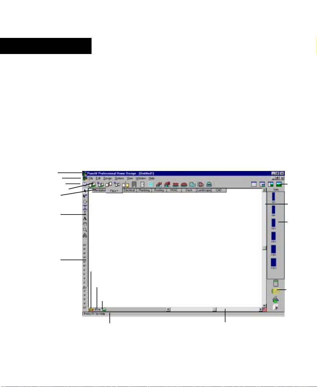
Chapter 2
Window Layout
The Master Landscape window provides an assortment of features that make it easy to
create precise home plans. This chapter describes the basic components.
In most cases, this chapter does not provide detailed information on standard Windows
concepts or on specific menu items. For information on standard Windows concepts, such
as the mouse, the Control menu, the window border, the maximize button, dialog box
controls and so on, refer to Windows online Help.
title bar
menu bar
tool guides
plan toolbar
plan tabs
standard
toolbar
LiveView
icons
vertical
scroll bar
preview
bar
elevation
slider
virtual
ruler
measurement
tools
working floor
button
status bar
design window
horizontal scroll bar
PUNCH! Master Landscape & Home Design User’s Guide
launch
buttons
11
Page 22

Chapter Window Layout
2
Title Bar
The title bar extends across the top of the application window. It displays the name of the
program and the name of the current drawing file. Using the buttons at the right end of the
title bar you can minimize, maximize, close or restore the window. You can also
maximize or restore a window by double-clicking on the title bar. Double-clicking the
Control menu box at the left end of the title bar is a quick way to exit. If the application is
running in a window rather than maximized, dragging the title bar moves the entire
window on the desktop.
Menu Bar
You can choose menu items using either the mouse or the keyboard. To use the mouse,
click the menu name, when the menu drops down, click the item you want. Menu items
with an arrow to the right display cascading menus when you place the pointer over one of
them. When you highlight a menu item, a description is displayed on the status bar.
To use the keyboard, press the ALT key and type the underlined letter in the menu name,
then type the underlined letter in the menu item’s name. If there is a cascading menu, you
must type another letter. You can also use the arrow keys to move through menu items and
press ENTER to select one. The ESC key backs out of the menu items one level at a time.
There are single-key or key combination shortcuts for certain freq uently-used m enu items.
Each menu lists available shortcut keys to the right of the item’s name. You can use the
techniques for choosing menu items in combination.
Plan Tabs and Toolbars
Clicking one of the plan tabs will activate the toolbar for that plan layer. For example, if
you select the Landscape tab, the Landscape toolbar will appear. In addition, when you
click the small arrow next to the title of the tab you have the option of viewing or hiding
other plans. This will be useful, for example, if you want to see the foundation plan with
landscaping, but without exterior and interior walls.
To find out what a certain tool represents, hold the pointer over the tool and read the
description on the status bar at the bottom of the window.
12
PUNCH! Master Landscape & Home Design User’s Guide
Page 23
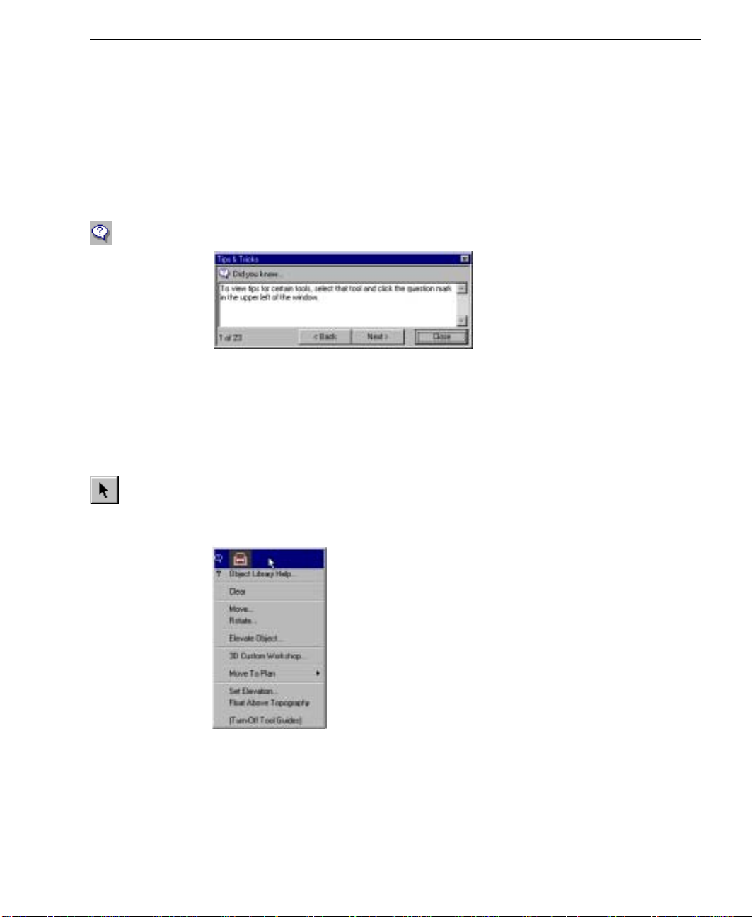
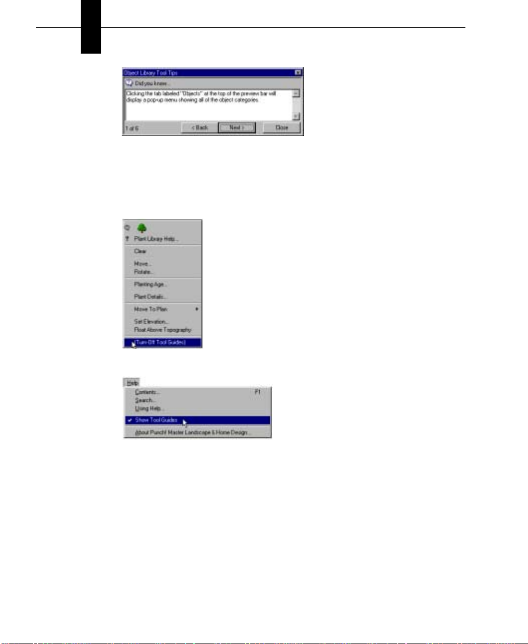
Tool Guides
Master Landscape makes it easy to get started by providing users with tips & tricks for
each Tool. Tool Guides provide information about each tool and some general information
about the program. Tool Guides can be turned off and on to suit your needs.
To access general tool guides
■
On the Standard toolbar, click the Tool Guide Tool.
To access tool guides for a specific tool
1 On any plan tab, click the tool you want to learn more about.
2 Click the Tool Guide tool, the Tips & Tricks menu for that tool is displayed.
To access tool guides for a part of your 2D drawing
Tool Guides
1
On the Standard toolbar, click the Selection Tool.
2 Click the feature, object or plant that you want to learn more about. The Quick Access
menu for that feature, object or plant is displayed on the right side of the window.
3 Click the Tool Guide listing at the top of the pop-up window. The Tool Tips menu for
that feature, object or plant is displayed.
PUNCH! Master Landscape & Home Design User’s Guide
13
Page 24
Chapter Window Layout
2
4 (optional) Click Back or Next to cycle through the tips available for that feature, object
or plant.
To turn tool guides on and off
■
To turn off Tool Guides, click (Turn-Off Tool Guides).
■
To turn on Tool Guides, on the Help Menu click (Turn-Off Tool Guides).
14
PUNCH! Master Landscape & Home Design User’s Guide
Page 25
Elevation Slider
With Master Landscape’s Elevation Slider you can easily move selected items vertically.
This feature makes it a snap to make sure windows, doors, plants and so on are in exactly
the position you want. Simply select the object or feature to be raised and move slider by
clicking and dragging with the mouse. For a more information, see “Using Elevation
Slider” on page 186.
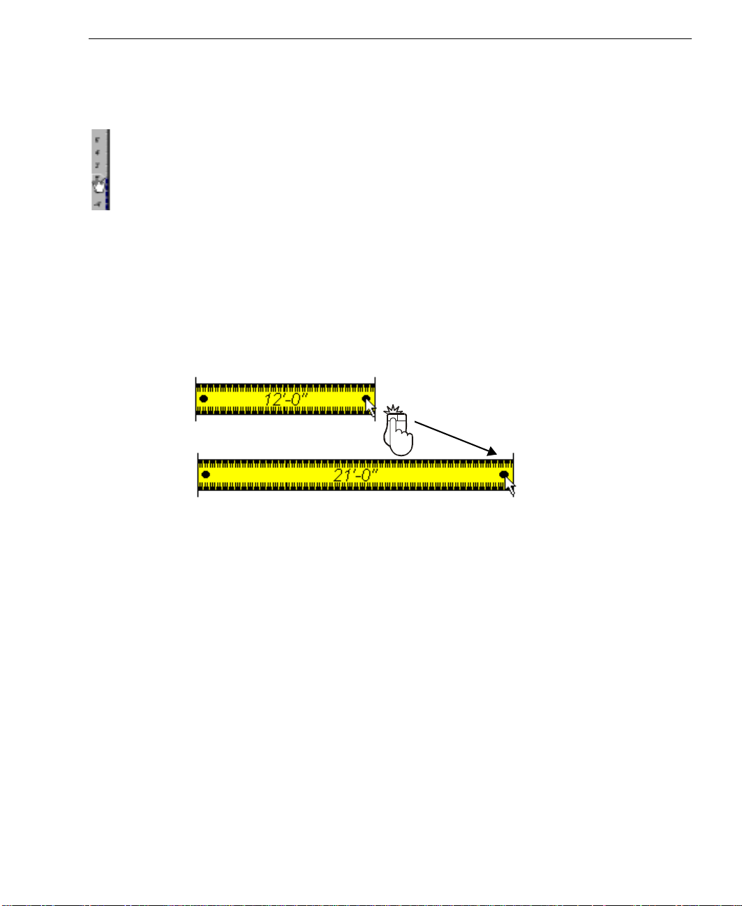
Virtual Ruler
The Virtual Ruler works like a real-world tape measure. It stores away in the corner of the
window until you need it, then with one click it is displayed in the middle of the window,
where you can move it into any position necessary to make a needed measurement. It then
stores away until you need it again. To move the Virtual Ruler, click and drag from the
center. To resize, click and drag on one of the large black dots at either end.
Elevation Slider
Drag
You are not constrained to vertical or horizontal, the Vertical Ruler can be stretched in any
direction necessary.
PUNCH! Master Landscape & Home Design User’s Guide
15
Page 26

Chapter Window Layout
2
Measurement Tools
The measurement tools include associative dimensions, window/door callouts and the
shortcuts to calculate floor square footage.
Associative Dimensioning are the measurements that appear as you are adding features.
For example, the Associative Dimensioning feature will show how far from the ends of
each wall the window is positioned.
When the Window/Door Callouts option is checked, the measurements of all window and
door openings will be shown with the wall measurements and be displayed in the
floorplan view.
Selecting one of the three square footage options will cause Master Landscape to make
that calculation and display it in the Status Bar.
Working Floor Button
Use the Working Floor button to switch the current view based on the number of floors in
your home plan. When you click the Working Floor button, a pop-out menu is displayed.
Simply click the floor on which you would like to work to switch the current worki ng
floor.
Status Bar
The status bar is located in the lower left of the window and displays prompts, program
messages and measurements. It is a good place to look when you are holding the pointer
over certain buttons or menu items to find their function.
Scroll Bars
Scroll bars provide a way for you to pan across the drawing, that is, to change the part of
the drawing visible in the window without changing the level of magnification. To pan the
drawing in small increments, click the scroll arrow that points in the direction you want to
pan. To pan in larger increments, click the control shaft, between the scroll box and a
scroll arrow. To pan by a custom increment, drag the scroll box in the direction you want
to pan.
16
PUNCH! Master Landscape & Home Design User’s Guide
Page 27
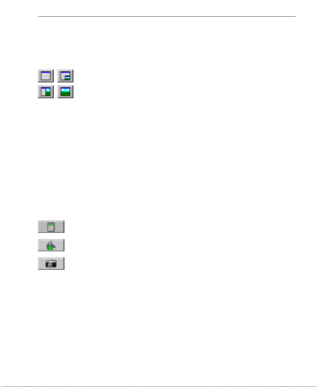
LiveView Icons
It is in the LiveView window where you see your designs come to life! The default view is
Plan Full View. When you load Master Landscape, this is the view you wil l see. With the
3D Quarter View option, use most of your window for drawing, yet be able to view your
design in 3D. For a full explanation see the chapter titled “Working with LiveView”,
which begins on page 189.
When you want to focus primarily on your 2D actions while maintaining a clear view of
the 3D design, select Split Plan/3D View. Then, when you’re ready to add textures and
colors to your Dream Home it will be easier in the 3D Full View mode.
Preview Bar
You can click and drag objects, textures and colors from the Preview Bar onto your plan.
The Preview Bar changes to reflect the current design mode. For instance, if you are
installing doors, the bar will display some of the most common styles of doors; this will
help you specify the style before you start drawing. The Preview Bar provides the easiest
and quickest way to customize a home plan.
Launch Buttons
LiveView Icons
Clicking one of the launch buttons starts one of the associated Master Landscape
programs.
Launch Landscape Estimator. To learn more about Landscape Estimator, see the chapter
titled “Using Landscape Estimator”, which begins on page 213.
Launch 3D Custom Workshop. For more information, see “3D Custom Workshop”, which
begins on page 233.
Insert a PhotoView Image. For more information on PhotoView, see the chapter titled
“Using PhotoView”, which begins on page 219.
PUNCH! Master Landscape & Home Design User’s Guide
17
Page 28

Chapter Window Layout
2
18
PUNCH! Master Landscape & Home Design User’s Guide
Page 29

Chapter 3
A Quick Tour
To get the most benefit from Punch! Master Landscape and Home Design, you should
take a minute to become familiar with some of its basic concepts. This chapter describes a
few settings you should know, as well as some of the terms used throughout this guide.
Punch! Master Landscape and Home Design is not just one software application, but
several applications that can be used together. Once you’ve mastered Master Landscape,
additional tools are available to customize your home plans: Landscape Estimator,
Cabinet Wizard, PhotoView, RealModel and 3D Custom Workshop. Information on the
use of all these tools can be found in this User’s Manual.
With Master Landscape you can set a precise drawing scale, define units of measurement
and set the reference grid. There are also many performance settings you can apply to
optimize drawing speed and 3D viewing.
PUNCH! Master Landscape & Home Design User’s Guide
19
Page 30

Chapter A Quick Tour
3
About This Guide
The text and graphics in this guide are tailored to help you find the information you need
quickly and get the most out of Master Landscape. Each section of this guide is divided
into a series of step-by-step instructions, making it easy for you to scan a page to find
exactly what you need. You can also refer to the index for additional topics on the same
subject, if necessary.
Instructions for installing and using Microsoft Windows do not appear in this guide. If
you’re uncomfortable with your knowledge of Windows or with the concepts associated
with a user interface object, you should review Windows online Help before attempting
any serious work with Master Landscape.
Basic Terms
The following is a list of terms used throughout this guide. Take a moment to familiarize
yourself with the language used in this guide and to reinforce your understanding of basic
terminology.
Click
Pressing and releasing the left mouse button once.
Right-click
Pressing and releasing the right mouse button once.
Double-click
Pressing and releasing the left mouse button twice.
Click and drag
Pressing the left mouse button, holding it down and moving the mouse simultaneously.
Drag-and-drop
Clicking to select an item, holding down the mouse button, then dragging and releasing.
Scroll
Using the scroll bars on the sides of the application window by clicking the slider box,
holding down the mouse button and dragging.
20
PUNCH! Master Landscape & Home Design User’s Guide
Page 31

Right-Click Pop-up Menus
Graphic Cues
This guide uses several types of graphic elements. Some show the window or a dialog box
that will appear during an operation. When this type of graphic illustration is used, every
effort is made to show the element exactly as it is displayed on window.
Graphic Cues Used in this Guide
Convention Meaning
mouse click that selects a point—the number, when present, specifies the mouse
click’s position in a series of clicks
2
click and drag operation—beginning of arrow indicates where to start; end of
arrow indicates where to stop
Drag
a right mouse click —the number, when present, specifies the mouse click’s
position in a series of clicks
2
Right-Click Pop-up Menus
Master Landscape provides access, with a right mouse click, to many commonly-used
commands. One-click accessibility is available to commands from cut and paste, to
specifying where dimensions appear, to customizing grid properties and so on.
To access the plan option right-click menu
1
On the Standard toolbar, click the Selection Tool.
2 Right-click on your design window. The plan option pop-up
menu is displayed.
Note: Be sure nothing is selected when performing the rightclick; if something is selected you will receive a different
editing pop-up menu.
3 Move the mouse down the menu until the option you want is
highlighted.
4 Click the mouse. The option you selected is displayed.
PUNCH! Master Landscape & Home Design User’s Guide
21
Page 32

Chapter A Quick Tour
3
To access the plan edit right-click menu
1 On the Standard toolbar, click the Selection Tool.
2 Right-click a wall on your design window. The plan edit
pop-up menu is displayed.
3 Move the mouse down the menu until the option you want is
highlighted.
4 Click the mouse. The option is displayed.
Note: This menu might differ slightly from the one shown at
right depending on whether an exterior or an interior wall is
selected.
To access the plant edit right-click menu
1 On the Standard toolbar, click the Selection Tool.
2 Right-click a plant on your design window. The plant edit
pop-up menu is displayed.
3 Move the mouse down the menu until the option you want is
highlighted.
4 Click the mouse. The option you selected is displayed.
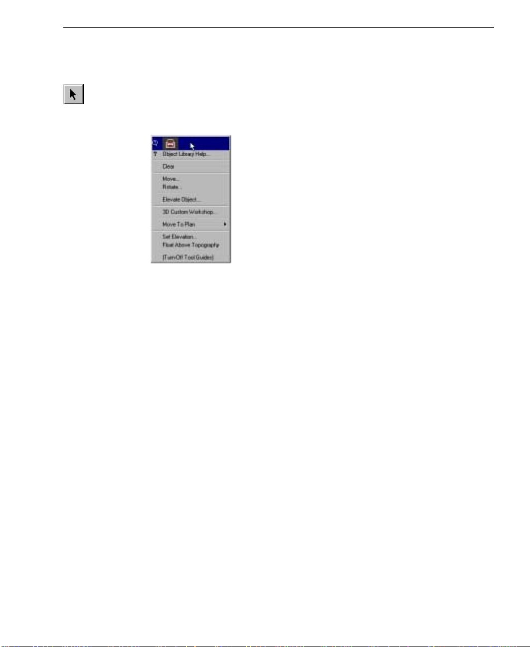
To access the object edit right-click menu
1 On the Standard toolbar, click the Selection Tool.
2 Right-click an object on your design window. The object
edit pop-up menu is displayed.
3 Move the mouse down the menu until the option you want is
highlighted.
4 Click the mouse. The option you selected is displayed.
22
PUNCH! Master Landscape & Home Design User’s Guide
Page 33

Changing the Lot Size
With Master Landscape you can define a lot size that matches your physical lot up to a
maximum of 500 x 500 feet. The default lot size is 200 x 200 feet. For more information
on matching your lot if it is not rectangular, see “Defining the Property Line”, which
begins on page 58.
To set the lot size
1 On the Design menu, click Lot Size or press CTRL+L. The Lot Size dialog box is
displayed.
2 Type the new lot size in the dialog box, then click OK. The lot is altered
3 (optional) Click to select meters if you want to use metric measurements.
Setting the Scale
Changing the Lot Size
Scale is the ratio between real-world size of objects and items in your drawing and their
size when printed.
The default drawing scale is 1/3" = 1', meaning that 1/3" on your drawing plan equals one
foot in real-world size. You can customize scale settings at any time to suit your needs as
well as print your drawing to scale.
To set the drawing scale
1 On the Design menu, click Plan Scale. The Plan Scale dialog box is displayed.
2 Click a new scale setting, then click OK. The new scale is applied to your plan
drawing.
PUNCH! Master Landscape & Home Design User’s Guide
23
Page 34

Chapter A Quick Tour
3
Setting Unit of Measurement
You can set units of measurement in Master Landscape by selecting either English
measurements in feet and inches or Metric measurements in meters and centimeters.
To set the unit of measurement
1 On the Design menu, click Unit of Measure. The Unit of Measure dialog box is
displayed.
2 Click either English or Metric, then click OK. The unit of measurement you selected is
applied.
Using the Grid
With Master Landscape you can set specific grid properties that aid in drawing your home
plan. You can set points based on the reference grid which is useful when you want to
make sure certain points are specified precisely.
Grid settings have a direct impact on the ease of aligning objects, snapping objects to the
grid and so on. When using the Snap to Grid feature, items that are dragged and dropped
on the design window are automatically snapped, or placed, to align with the current grid.
By default, Snap to Grid is turned on.
You can customize grid settings by selecting grid spacing, grid style and whether the grid
is hidden from view or displayed. By default, the grid is set at 12 inches, making it easy to
visualize that each plan square is exactly one square foot, but can be customized to meet
your particular design needs.
Grid properties can also be set by accessing the right-click menu with nothing selected,
see “To access the plan edit right-click menu” on page 22 for more information.
To define Snap to Grid settings
1 On the Options menu, click Grid Properties or right-click on your design wind ow and
click Grid Properties on the pop-up menu that is displayed. The Grid Properties dialog
box is displayed.
24
PUNCH! Master Landscape & Home Design User’s Guide
Page 35

Using the Grid
2 On the Grid Spacing dialog box, type new measurements into the Snap Grid section,
then click OK. Items you draw or drag-and-drop into the design window will now snap
to the measurements you defined.
Note: Initially, the grid is set at 12 inches, making it easy to visualize each plan square as
exactly one square foot, but can be customized to meet your particular design needs.
Note: Snap settings can be set as low as 0.10 inch (English), 0.002 m (Metric) and still
show visible movement along the grid. Snap settings can be set as high as 500 inches
(English), 12.70 m (Metric).
To select grid spacing
1 On the Options menu, click Grid Properties or right-click on your design wind ow and
click Grid Properties on the pop-up menu that is displayed. The Grid Properties dialog
box is displayed.
2 Type new horizontal and vertical measurements in the Grid Dots/Lines section of the
Grid Spacing page, then click OK. The new grid spacing measurements are applied.
PUNCH! Master Landscape & Home Design User’s Guide
25
Page 36

Chapter A Quick Tour
3
To change the grid style
1 On the Options menu, click Grid Properties or right-click on your design wind ow and
click Grid Properties on the pop-up menu that is displayed. The Grid Properties dialog
box is displayed.
2 Click the Grid Style page tab.
3 Click either Grid Dots or Grid Lines, then click OK. The new grid style is applied.
Note: Grid Dots/Lines can be set to as low as 1 inch (English), 0.02 m (Metric) and still
be viewable. Grid Dots/Lines can be set as high as 500 inches (English), 12.70 m (Metric).
To move objects/features along the grid style
1
On the Standard toolbar, click the Selection Tool.
2 Click the object or feature you want to move.
3 Using the arrow keys on your keyboard, move the object or feature into position.
Note: Each time you press an arrow key, the object or feature will move one increment
that you have set in “To define Snap to Grid settings” on page 24.
To turn off Snap to Grid
■
On the Options menu, click to uncheck Snap to Grid, press CTRL+R, or right-click on
your design window and click Snap to Grid on the pop-up menu. The feature is
disabled. To enable Snap to Grid, simply recheck the menu item.
To display the grid
■
On the Options menu, click to check Grid Visible or right-click on your design
window and click Grid Visible on the pop-up menu that is displayed. The grid is
displayed on the design window.
26
PUNCH! Master Landscape & Home Design User’s Guide
Page 37

Chapter 4
File Management
When you start Master Landscape, a new blank drawing file is displayed. If you are
returning to work on an existing drawing, you must open it, or display it on the screen.
Opening a file involves clicking Open on the File menu and specifying the name of the file
you want to open. Once you have opened a file, you can edit, import, export, print, view
and save it.
You can have more than one file open at a time. The exact number of files you can have
open depends on the amount of memory in your system and the complexity of the home
plan file. When you open a file, Master Landscape displays it in a new window.
The changes you make to a plan drawing occur only in your computer’s memory until you
save them. To preserve a drawing for later use, you must save it to a file. If you want to
save a drawing using its current name or if you want to save a new, untitled drawing, use
Save. If you want to save a drawing using a new name, use Save As.
At any point during the design process you can import objects created in 3D Custom
Workshop or cabinets from Cabinet Wizard. You can also export your 2D design as a 2D
DXF file.
PUNCH! Master Landscape & Home Design User’s Guide
27
Page 38

Chapter File Management
4
Opening a File
Opening a file copies the data it contains into memory, making it available for you to edit
or print the plan drawing.
To open an existing file
1 On the File menu, click Open. The Open dialog box is displayed.
2 In the File Name box, type the name of the file you want to open, or search for the file
by switching folders or drives.
3 When you see the name of the file you want to open, click to select it.
4 Click OK.
Saving a File
When you open a file, Master Landscape copies the file to your computer’s memory. As
you work, you modify the copy stored in memory. Any system failure or loss of power
destroys that copy. To save your work permanently, you must save it to a file on a disk. A
good rule of thumb is to save every 15 minutes or after you’ve completed any work you
wouldn’t want to redo.
When you click the Save command, Master Landscape saves the active drawing using the
name and location you last gave it. You can create more than one version of a drawing or
save copies on another disk for safekeeping. You can save each version under a different
name, or you can save them under the same name in different folders or on different disks.
To save an existing file
■
On the File menu, click Save or right-click, then click Save on the pop-up menu that is
displayed or press Ctrl+S.
To save a new, unnamed file
1 On the File menu, click Save As. The Save As dialog box is displayed.
2 In the File Name text box, type a name. Master Landscape automatically adds the PRO
extension, unless you specify another extension.
3 Click OK.
28
PUNCH! Master Landscape & Home Design User’s Guide
Page 39

To save a file to a different name, drive, or folder
1 On the File menu, click Save As. The Save As dialog box is displayed.
2 If you want to save the drawing under another name, type a name in the File Name text
box.
3 If you want to save the drawing to a different drive or folder, click a different drive and
folder, or type the complete path in the File Name text box.
4 Click OK.
Closing a File
When you finish working with a file, close it to remove the window from the screen and to
free up your computer’s memory. When you are done working in Master Landscape, close
all your files and exit the program.
To close a file
■
On the File menu, click Close. If you have unsaved changes in your plan drawing,
Master Landscape prompts you to save them before it closes the file.
To close all open files and exit Master Landscape
■
On the File menu, click Exit. If any open drawings have unsaved changes, Master
Landscape prompts you to save them before it closes their files.
Closing a File
Accessing the Pre-Drawn Homeplans
Master Landscape includes twenty homeplans for you to alter. The included homeplans
are located in the directory where you installed the program, in a subdirectory called
“Plans”.
To open a pre-drawn homeplan
1 On the file menu, click Open.
2 Navigate to the directory where Master Landscape is installed.
3 Double-click the Plans subdirectory. The subdirectory opens.
4 Click the plan you want to open. Click OK.
PUNCH! Master Landscape & Home Design User’s Guide
29
Page 40

Chapter File Management
4
Note: All plans included with Master Landscape are the copyright of Wolfgang Trost
Architects. The plans and 3D computer images are for conceptual purposes only. You
must have any plans provided in, or generated by, Punch! Master Landscape and Home
Design checked by a licensed architect before you build. Punch Software LLC and
Wolfgang Trost Architects are not liable for errors, omissions or any other deficiencies in
these conceptual plans. Complete sets of building plans for these homes are available by
contacting Wolfgang Trost Architects at www.wolfgangtrost.com
Importing Files
Punch! Master Landscape and Home Design is 9 programs in one. All of these programs
integrate seamlessly; objects created with Punch! 3D Custom Workshop are available for
import into your floor plan.
To import a 3D Custom Workshop object
1 On the File menu, click Import>Punch! 3D Custom Workshop Object. The Import
Punch! 3D Object dialog box is displayed.
2 In the File Name box, type the name of the file you want to open, or search for the file
by switching folders or drives.
3 When you see the name of the file you want to open, click to select it.
4 Click OK. The object is placed in the center of your 2D design.
Note: Double-click the object to re-open it in 3D Custom Workshop.
30
PUNCH! Master Landscape & Home Design User’s Guide
Page 41

Exporting Files
With Master Landscape, you can export your design several ways. Export to BMP format,
making the contents of the 3D LiveView window available to be emailed. Export to 2D
DXF format, where your 2D plan design is available for importing in any program that
supports 2D DXF.
You can also export a rendering to BMP format. Files can be export in BMP format in
Textured, Wire-Frame and ClearView modes. The exported file will appear just as your
LiveView window does. Be sure to render in high-resolution your drawing before
exporting. Size is also controlled by how your LiveView window appears, the larger the
LiveView window, the larger the BMP file will be. For more information on controlling
the LiveView environment, see “Working with LiveV iew”, which begins on page 189
To export to BMP
1 On the File menu, click Export>BMP. The Export BMP dialog box is displayed.
2 In the File Name text box, type a name. Master Landscape automatically adds the
BMP extension, then click OK.
Note: For instructions on printing the BMP file, see “Printing a 3D LiveView
Rendering” on page 35.
Exporting Files
To export to 2D DXF
1 On the File menu, click Export>DXF. The Export DXF dialog box is displayed.
2 In the File Name text box, type a name. Master Landscape automatically adds the DXF
extension, then click OK.
Printing Floorplans
Master Landscape prints using the current Windows printer. You can, however, print
using any installed printer. Using the Print dialog box you can specify a printer or plotter
from those currently installed. Your can print your drawing in color or in black & white; it
can be printed to scale or you can print it all on one page, whatever you require. Follow
these steps to print your 2D drawing.
To print to fit page
1 On the File menu, click Print to Fit Page or press Ctrl+P. A Print Manager menu will
ask if you want to print your drawing in color. Click Yes to print in color, click no to
print in greyscale.
PUNCH! Master Landscape & Home Design User’s Guide
31
Page 42

Chapter File Management
4
Note: Gridlines will print if they are visible when the drawing is printed.
2 The Print dialog box is displayed.
3 Click the down arrow next to the printer name.
4 Click the printer you want to use.
5 Click the Properties button. The Properties menu is displayed.
Note: The following Properties menu is that of a popular color printer. Refer to your
printer’s documentation on the use of its specific features.
6 Select the paper orientation.
7 Select the paper size. Typically, this will be either 8 1/2x11 in (letter) or 8 1/2x14 in
(legal).
32
PUNCH! Master Landscape & Home Design User’s Guide
Page 43

Printing Floorplans
8 Click the down arrow next to media type. Then select the required media.
9 Click either Auto Feeder or Manual Feed as your paper feed method, then click OK.
To print to scale
1 On the Design menu, click Plan Scale. The Plan Scale dialog box is displayed.
2 Click the radio button next to the scale you want to use. Click OK.
Note: Gridlines will print if they are visible when the drawing is printed.
3 On the File menu, click Print to Scale. A Print Manager menu will ask if you want to
print your drawing in color. Click Yes to print in color, click no to print in greyscale.
4 The Print dialog box is displayed.
5 Click the down arrow next to the printer name.
6 Click the printer you want to use.
7 Click the Properties button. The Properties menu is displayed.
Note: The following Properties menu is that of a popular color printer. Refer to your
printer’s documentation on the use of its specific features.
PUNCH! Master Landscape & Home Design User’s Guide
33
Page 44

Chapter File Management
4
8 Select the paper orientation.
9 Select the paper size. Typically, this will be either 8 1/2x11 in (letter) or 8 1/2x14 in
(legal).
10 Click the down arrow next to media type. Then select the required media.
11 Click either Auto Feeder or Manual Feed as your paper feed method, then click OK.
34
PUNCH! Master Landscape & Home Design User’s Guide
Page 45

Printing a 3D LiveView Rendering
Master Landscape streamlines the process used to print the 3D LiveView images. With
just a couple clicks, you can print beautiful, full-color renderings of your design.
To print a 3D LiveView rendering
1 On the File menu, click Print 3D LiveView, then select the quality needed. The print
dialog box is displayed.
2 Click the down arrow next to the printer name.
3 Click the printer you want to use.
Printing a 3D LiveView Rendering
4 Click the Properties button. The Properties menu is displayed.
Note: The following Properties menu is that of a popular color printer. Refer to your
printer’s documentation on the use of its specific features.
5 Select the paper orientation.
PUNCH! Master Landscape & Home Design User’s Guide
35
Page 46

Chapter File Management
4
6 Select the paper size. Typically, this will be either 8 1/2x11 in (letter) or 8 1/2x14 in
(legal).
7 Click on the down arrow next to media type. Then select the required media.
8 Click either Auto Feeder or Manual Feed as your paper feed method.
9 Click OK.
36
PUNCH! Master Landscape & Home Design User’s Guide
Page 47

Chapter 5
Dimensioning, Measuring
and Text
Often, drawing a plan to scale is not enough to convey precise measurements. In such
cases, you must note the measurements using manual dimension notes. Master Landscape,
by default, automatically displays dimensions as you draw. This makes it easy to create
accurate drawings from the start.
Using tools available in Master Landscape, you can measure items that are not
automatically dimensioned using the Dimension and Dimension Wall Tools or the Virtual
Ruler.
You can also obtain total square footage measurements for each floor of your home design
with the Square Footage menu item.
With the text tools you can add text to any area of your drawing. This feature is useful if
you’d like to name your home plan, or add your address to the final drawing, for instance.
You can select from any font already installed on your computer, as well as select style
and size.
This chapter describes the dimension and measurement tools in Master Landscape and
how to add text to your drawing.
PUNCH! Master Landscape & Home Design User’s Guide
37
Page 48

Chapter Dimensioning, Measuring and Text
5
Dimensioning
Master Landscape automatically displays dimensions as you draw, making it easy to
precisely place walls, doors and other items in your plan drawing. The powerful
Dimension Wall tool will be especially useful to add interactive dimensions between
walls, where they are not automatically generated. Dimensions drawn with the Dimension
Wall tool are automatically updated when either wall is moved. You’ll find this tool
extremely useful when measuring between the main house and the walls of other
buildings, like a garden shed or playhouse. In some instances, you might want to print
your plan drawing without dimension annotation. You have the option of turning off
automatic dimensioning if you don’t want them displayed on the drawing page or as you
draw.
To use the dimension wall tool
1 On the Standard toolbar, click the
2 Click a wall on the design window to define the starting point, hold down the mouse
button and drag to the second wall.
3 Release the mouse button to set the measurement.
Note: Right click the dimension to specify whether the measurement is to be made from
the center of the wall or the edge.
Dimension Wall Tool.
To use the dimension tool
1 On the Standard toolbar, click the
2 Click on the design window to define the starting point, hold down the mouse button
and drag to the ending point of the measurement you require.
3 Release the mouse button to set the measurement.
To turn off automatic dimensioning
■
On the Options menu, click to uncheck Automatic Dimensioning.
OR
■
At the bottom of the window, click the Dimension button, then click to uncheck
Automatic Dimensioning on the pop-up menu that is displayed.
To hide window and door dimensions
■
At the bottom of the window, click the Dimension button, then click to uncheck
Window/Door callouts on the pop-up menu that is displayed.
38
PUNCH! Master Landscape & Home Design User’s Guide
Dimension Tool.
Page 49

Using the Virtual Ruler
To change the end point style
1 On the Standard toolbar, click the Selection Tool.
2 Right-click the dimensions you want to customize, then click Dimensions on the pop-
up menu that is displayed. The Dimension Properties menu is displayed.
3 Click to select the end point style you want to use, then click OK.
To remove custom dimensions
1 On the Standard toolbar, click the Selection Tool.
2 Right-click the dimensions you want to remove, then click Clear on the pop-up menu
that is displayed or press DELETE.
Using the Virtual Ruler
The Virtual Ruler is a handy feature for measuring items in your home plan that are not
automatically dimensioned. You can “undock” the ruler at any time, leaving it active, or
hide it from view with one mouse click. The Virtual Ruler is an easy way to measure at an
angle, too.
To measure using the Virtual Ruler
1
Click the Virtual Ruler button at the bottom of the design window. The Virtual Ruler is
displayed on the drawing page.
2 Click one of the black circles on the ruler edges and drag in the direction you want to
measure. The measurement is displayed in the center of the Virtual Ruler.
3 (optional) Click the center of the Virtual Ruler and drag it to a new location on the
design window.
To hide the Virtual Ruler
■
Click the Virtual Ruler button at the bottom of the design window. The Virtual Ruler is
“docked.”
PUNCH! Master Landscape & Home Design User’s Guide
39
Page 50

Chapter Dimensioning, Measuring and Text
5
Calculating Square Footage
Master Landscape can automatically calculate square footage of each floor of your home
plan. This feature makes it easy to figure how much carpet you’ll need to cover the first
floor, for instance, or simply estimate your overall home size. If square footage is
incorrect, check to make sure the exterior perimeter is intact. For more information, see
“Drawing Exterior Walls”, which begins on page 92.
To calculate floor square footage
■
At the bottom of the window, click the Dimension button, then click First Floor Square
Footage (or Second or Third floor). Master Landscape calculates the square footage
and the total is displayed on the status bar.
Adding Text
Use text to add information to your drawing. For example, you might add text to annotate
rooms, specify a home address, the date the drawing was created or a specific feature in
your plan. Master Landscape gives you the flexibility to place text anywhere in your plan
drawing using different formatting techniques for each text instance. Text you place in
your drawing is displayed on all 2D printed output.
To place text in your drawing
1
On the Standard toolbar, click the Text button.
2 Click the area where you want to place text on the drawing page. A white text box,
with cursor, is displayed.
3 Type text.
4
Click the selection tool on the Standard toolbar to end text mode.
To change formatting of existing text
1 Using the selection tool, click the text you want to change. Selection handles appear
around the text.
2 On the Options menu, click Text or double-click the selected text. The Font dialog box
is displayed.
40
PUNCH! Master Landscape & Home Design User’s Guide
Page 51

3 To change the text font, click a new font on the Font list.
4 To change the text style, click a new style on the Font style list.
5 To change the text size, click a new size on the Size list.
6 Click OK.
Adding Text
PUNCH! Master Landscape & Home Design User’s Guide
41
Page 52

Chapter Dimensioning, Measuring and Text
5
42
PUNCH! Master Landscape & Home Design User’s Guide
Page 53

Chapter 6
Controlling Views
Master Landscape provides many options for looking at your home plan onscreen. You
can display several windows, each containing a different view of your plan. This gives
you the flexibility to view your drawing as a 2D plan, as a 2D plan with a corresponding
3D view or using Punch! LiveView.
When viewing your 2D home plan, you can magnify the view by zooming in, reduce the
view by zooming out, use the Viewpoint tool to display a specific area of your drawing or
pan the view in any direction.
3D viewing provides many options, from walking through the home plan to flying around
the plan or viewing the framing or completion phase of your project. You can adjust 3D
display settings using a variety of viewing features including adding shadows, for a
realistic effect, or adjusting the lighting intensity of the view. Finally, you can create a
photo-realistic view of your home plan.
In this chapter, you’ll learn about the numerous commands designed to let you view your
home in both 2D and 3D.
PUNCH! Master Landscape & Home Design User’s Guide
43
Page 54

Chapter Controlling Views
6
Viewing the 2D Plan
When initially designing your home plan, you will probably want to view the 2D plan
view only. Once completed, you can view your plan in a combination of 2D and 3D or in
3D only. In addition, Master Landscape organizes your floorplan into layers which are
each easily accessible with a single mouse click. For example, you can choose to view the
deck plan with landscaping one moment, then quickly switch views to add the roof plan.
Any combination ... any time!
To view the 2D plan only
■
On the Window menu, click Plan Full View. The 2D plan view is displayed.
To view all 2D floor plan views at once
■
Click the Working Floor button at the left bottom of the design window, then click to
check View All Floors.
To view the working floor only
■
Click the Working Floor button at the left bottom of the design window, then click to
check View Working Floor Only.
To view drawing layer combinations
1 Click a plan tab.
2 Click the arrow to the right of the tab label. A drop-down menu will appear.
3 Click the plan you want to view.
4 (optional) Repeat until the combination you want is reached.
44
PUNCH! Master Landscape & Home Design User’s Guide
Page 55

Zooming In and Out in 2D
You can get a closer look at an area or see a larger portion of your plan drawing by
zooming in and out. By dragging over the drawing, the view enlarges or decreases
dynamically. You can also set the zoom factor to obtain exact zoom precision. Once
you’ve finished viewing your plan close-up, you can return to the previous, full view with
one mouse click.
To zoom in
1
On the Standard toolbar, click the Zoom button.
2 Click on the design window and drag in an upward direction to zoom in.
3 Click on the design window and drag in a downward direction to zoom out.
Note: When the mouse is clicked, the location of the cursor will be centered on the
design window.
To set the zoom factor
1 On the View menu, click Set Plan View Zoom. The Set Plan View Zoom dialog box is
displayed.
2 Type a new zoom factor, then click OK.
Zooming In and Out in 2D
To reset the 2D plan view
■
On the View menu, click Reset Plan View or press CTRL+E on your keyboard. Your
plan is reset to the original, default view.
Panning Across the 2D Drawing
You can move the design window to see portions of the plan which are outside the current
view by panning. Panning also makes it easy to slowly view areas of your drawing pieceby-piece.
To pan in any direction
1
On the Standard toolbar, click the Pan button. The pointer changes to reflect Pan
mode.
2 Click on the design window and drag in the direction you want to view. The view
changes dynamically as you move the mouse.
PUNCH! Master Landscape & Home Design User’s Guide
45
Page 56

Chapter Controlling Views
6
Using Viewpoints
Using the Viewpoint tool, you can select a specific area in your 2D plan drawing and view
it in 3D. This is useful if you want to view a specific wall inside your home. Simply click
the area you want to view in the 2D plan window and Master Landscape launches the
LiveView window displaying the area you selected in 3D.
To select an area in the 2D plan and view it in 3D
1 On the Standard toolbar, click the
2 Click the area in the 2D plan window that you want to view. Master Landscape
generates the 3D view and it is displayed in the LiveView window.
3 (optional) To change the LiveView dynamically, click the viewpoint arrow in the 2D
plan view, hold down the mouse button and drag.
4 (optional) To close the LiveView window and return to the 2D plan view, click Plan
Full View on the Window menu or click the Plan Full View icon.
Viewpoint Tool. A 3D LiveView window opens.
46
PUNCH! Master Landscape & Home Design User’s Guide
Page 57

Arranging 2D and 3D Windows
There are several ways to arrange 2D plan and 3D LiveView windows while you’re
working. You can split the window, displaying both views, view only the plan view, view
only the 3D view or display the 3D view in a smaller window with the plan view. You are
not limited to the four preset arrangements, you can resize and reposition the LiveView
window to fit your work area. LiveView options are also available from the right-click
plan options menu. For more information, see “Moving around in 3D”, which begins on
page 191.
To display the 2D plan view only
■
On the Window menu, click to check Plan Full View or click the Plan Full View icon.
Arranging 2D and 3D Windows
PUNCH! Master Landscape & Home Design User’s Guide
47
Page 58

Chapter Controlling Views
6
To display the 2D plan view and a small 3D view
■
On the Window menu, click 3D Quarter View or click the 3D Quarter View icon.
To display a split 2D and 3D view
■
On the Window menu, click Split Plan/3D View or click the Split Plan Icon.
48
PUNCH! Master Landscape & Home Design User’s Guide
Page 59

Arranging 2D and 3D Windows
To display a 3D view only
■
On the Window menu, click 3D Full View or click the 3D Full View icon.
PUNCH! Master Landscape & Home Design User’s Guide
49
Page 60

Chapter Controlling Views
6
50
PUNCH! Master Landscape & Home Design User’s Guide
Page 61

Chapter 7
Working with Plan Tabs
Master Landscape utilizes a collection of layers which are accessible by clicking the tabs
along the top of the design window. You can customize which layer or combination of
layers you want to be active.
PUNCH! Master Landscape & Home Design User’s Guide
51
Page 62

Chapter Working with Plan Tabs
7
Selecting a Plan Tab
Using the easily-accessible plan tabs, you can quickly access each tool set at any time.
To select a plan tab
1 On the Standard toolbar, click the
2 Click the plan tab you want to use. The plan tab is selected and the tools available on
that tab appear.
Customizing Visible Plans
During the design of your floorplan, there may be times when you want certain layers, that
by default are hidden, to be visible. For example, while working on your deck plan, you
may need to see where landscape plants will be. Master Landscape makes it easy to
customize how you view your plan layers.
To hide a plan layer from view
1 On the Standard toolbar, click the Selection Tool.
2 Click the plan tab you want to use. The plan tab is selected and the tools available on
that tab appear.
3 Click the arrow to the right of the plan name, then click the plan layer you want
hidden.
Selection Tool.
Note: Items on a hidden layer are not available during a Select All process and will not
be moved along with the other items and features in your drawing.
52
PUNCH! Master Landscape & Home Design User’s Guide
Page 63

Moving Features to Different Plans
To view a plan layer
1 On the Standard toolbar, click the Selection Tool.
2 Click the plan tab you want to use. The plan tab is selected and the tools available on
that tab appear.
3 Click the arrow to the right of the plan name, then click the plan layer you want to
appear.
Moving Features to Different Plans
With Master Landscape you can move selections to different plan layers, Move to Plan
deletes these objects from their original position.
To move features from one plan to another
1
On the Standard toolbar, click the Selection Tool.
2 Click the feature or object you want moved. To select more than one object, press the
SHIFT key while clicking objects.
3 On the Edit menu, click Move to Plan, then specify the plan, where you want the
feature to appear, in the pop-up menu that is displayed.
4 (optional) Right-click the selection and click Move to Plan on the pop-up menu that is
displayed, then click which plan. The selection is moved to the plan you specified.
Note: Items on a hidden layer are not available during a Select All process and will not
be moved along with the other items and features in your drawing.
PUNCH! Master Landscape & Home Design User’s Guide
53
Page 64

Chapter Working with Plan Tabs
7
54
PUNCH! Master Landscape & Home Design User’s Guide
Page 65

Part 2
Creating Your Design
Chapter 8: Landscape Plan Tab . . . . . . . . . . . . . . . 57
Chapter 9: Floor Plan Tab . . . . . . . . . . . . . . . . . . . 91
Chapter 10: Roofing Plan Tab . . . . . . . . . . . . . . . 137
Chapter 11: Deck Plan Tab . . . . . . . . . . . . . . . . . 155
Chapter 12: CAD Plan Tab . . . . . . . . . . . . . . . . . 169
Page 66

Page 67

Chapter 8
Landscape Plan Tab
From simply drawing your property line to adding a flower bed near your front door to
designing an elaborate pool area, Master Landscape contains an extensive toolset to help
you design your outdoor living areas.
In this chapter, you will learn to recreate your lot’s topography, create flower beds and
other landscapes using flowers, shrubs and trees, add a berm or a pond and add pathways
and fencing to your home plan.
PUNCH! Master Landscape & Home Design User’s Guide
57
Page 68

Chapter Landscape Plan Tab
8
Defining the Property Line
If you are working in a confined or unusually-shaped area, you may want to define the
property lines. The property line will only appear in the 2D design window.
To define the property line
1 On the Landscape Plan tab, click the
2 Click on the design window to define the start point of the property line. A rubber-
band line is displayed and follows the pointer. This line signifies the first edge of the
property line. Notice that dimensions appear as you draw.
Property Line Tool.
3 Click and move the pointer to the next corner point. Repeat until you have completely
drawn the property line.
4 Right click to end drawing mode.
To edit the property line
1
On the Standard toolbar, click the Selection Tool.
2 Click the property line to select it.
3 Click a corner point of the property line, hold down the mouse button and drag.
4 Click the next selection point, hold down the mouse button and drag.
58
PUNCH! Master Landscape & Home Design User’s Guide
Page 69

Calculating Square Footage of the Property
To remove the property line
1 On the Standard toolbar, click the Selection Tool.
2 Click the property line to select it.
3 Press the DELETE key on the keyboard, or right-click, then click Clear on the pop-up
menu that is displayed.
Calculating Square Footage of the Property
You can easily calculate the square footage contained within the property lines you draw.
To calculate the square footage
1 On the Standard toolbar, click the Selection Tool.
2 Right-click the property line, then click Property Line Square Footage on the pop-up
menu that is displayed.
3 The calculation is displayed in the status bar at the bottom of the window.
PUNCH! Master Landscape & Home Design User’s Guide
59
Page 70

Chapter Landscape Plan Tab
8
Adding a Ground Fill Region
From simple, rectangular entry ways and flower beds to elaborate planting areas, Master
Landscape makes designing them easy. You can design flower beds to flawlessly integrate
with your home design.
To draw ground fill region
1 On the Landscape Plan tab, click the
2 Click on the design window to define the start point of the ground fill region. A
rubber-band line is displayed and follows the pointer. This line signifies the first edge
of the ground fill region. Notice that dimensions appear as you draw.
Ground Fill Tool.
3 Click and move the pointer to the next corner point. Repeat until you have completely
drawn the ground fill region.
60
PUNCH! Master Landscape & Home Design User’s Guide
Page 71
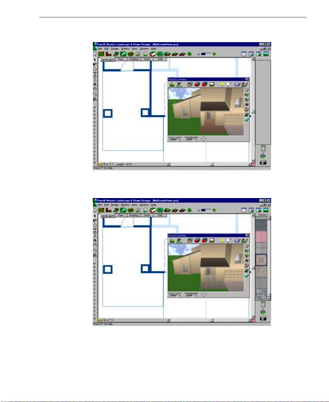
4 Right click to end drawing mode.
5 (optional) Drag and drop textures onto the region.
Adding a Ground Fill Region
PUNCH! Master Landscape & Home Design User’s Guide
61
Page 72

Chapter Landscape Plan Tab
8
To reshape a ground fill region
1
On the Standard toolbar, click the Selection Tool.
2 Click a side of the ground fill region you want to reshape.
3 Click a selection point of the ground fill region, hold down the mouse button and drag.
4 Click the next selection point, hold down the mouse button and drag.
To remove a ground fill region
1 On the Standard toolbar, click the Selection Tool.
2 Click the ground fill region you want to remove.
3 Press the DELETE key on the keyboard or right-click, then click Clear on the pop-up
menu that is displayed.
Calculating Square Footage of a Fill Region
With Master Landscape you can quickly estimate the square footage for a fill area. This
estimate will be useful when calculating the amount of mulch material.
To calculate the square footage of a fill region
1 On the Standard toolbar, click the Selection Tool.
2 Right-click a side of the fill region you want to calculate, then click Fill Region Square
Footage on the pop-up menu that is displayed.
3 The calculation is displayed in the status bar at the bottom of the window.
62
PUNCH! Master Landscape & Home Design User’s Guide
Page 73

Adding Berms or Ponds
Some of the most interesting landscaping will be created when you change the topography
by adding berms (hills), swales (valleys) or ponds to your yard.
To add a berm
1 On the Landscape tab, click the
Preview Bar will display preset distances of elevation or excavation.
2 Click the +12 inch preset.
3 Click on the design window to define the start point of the berm. A
rubber-band line is displayed and follows the pointer. Notice that
dimensions appear as you draw.
Adding Berms or Ponds
Curved Topography Tool. The
4 Click and move the pointer to the next point. Repeat until you have completely drawn
the berm.
5 Right click to end drawing mode. Notice that the lines will appear angular as they are
drawn, but will curve after the second mouse click.
PUNCH! Master Landscape & Home Design User’s Guide
63
Page 74

Chapter Landscape Plan Tab
8
6 Click the +24 inch preset.
7 Click on the design window to define an area somewhat smaller than the first area.
Note: By drawing gradually smaller areas or overlapping areas of differing heights, you
can create any height and shape of berm.
8 Right click to end drawing mode.
9 Repeat this process until the elevation you want is reached.
64
PUNCH! Master Landscape & Home Design User’s Guide
Page 75

Adding Berms or Ponds
To reshape a berm
1
On the Standard toolbar, click the Selection Tool.
2 Click the area you want to reshape.
3 Click a corner point of the area, hold down the mouse button and drag.
4 Click the next corner point, hold down the mouse button and drag.
To remove a berm
1 On the Standard toolbar, click the Selection Tool.
2 Hold the mouse button down as you drag a region selection around the berm you want
to remove.
3 Press the DELETE key on the keyboard or right-click, then click Clear on the pop-up
menu that is displayed.
To add a pond
1 On the Landscape tab, click the
2 Click on the design window, hold down the mouse button and drag.
3 Release the mouse button.
4 Click the
5 Click the Texture Tool in the 3D LiveView window.
3D Quarter View icon or on the Window menu, click 3D Quarter View.
Fill Tool.
6 Click the arrow to the right of the word Textures above the Preview Bar and select
Mulch.
PUNCH! Master Landscape & Home Design User’s Guide
65
Page 76

Chapter Landscape Plan Tab
8
7 Scroll to view the available textures until you locate the water textures.
8 Drag and drop the water texture onto the pond in the 3D LiveView window.
To reshape a pond
1
On the Standard toolbar, click the Selection Tool.
2 Click the pond you want to reshape.
3 Click a corner point of the pond, hold down the mouse button and drag.
4 Click the next corner point, hold down the mouse button and drag.
5 Repeat until needed shape is achieved.
66
PUNCH! Master Landscape & Home Design User’s Guide
Page 77

Drawing Sidewalks, Pathways or Driveways
To remove a pond
1 On the Standard toolbar, click the Selection Tool.
2 Hold the mouse button down as you drag a region selection around the pond you want
to remove.
3 Press the DELETE key on the keyboard or right-click, then click Clear on the pop-up
menu that is displayed.
Drawing Sidewalks, Pathways or Driveways
Using tools in Master Landscape you can design sidewalks, pathways and driveways
using the same Tool. Once a pathway is drawn, you can customize it by applying any
texture to suit your needs. For more information on color and texture, see the chapter titled
“Working with LiveView”, which begins on page 189.
To add a pathway
1 On the Landscape Plan tab, click the
displays predefined widths.
2 Click the pathway width to use. Use the scroll bar if the width is not
shown in the Preview Bar.
3 Click on the design window to define the start point of the pathway. A
rubber-band line is displayed and follows the pointer. Notice that
dimensions appear as you draw.
4 Click and move the pointer to the next point. Repeat until you have
completely drawn the pathway.
Pathway Tool. The Preview Bar
PUNCH! Master Landscape & Home Design User’s Guide
67
Page 78
Chapter Landscape Plan Tab
8
5 Right-click to end drawing mode.
Note: While drawing, curved pathways will appear angular, but will curve after the
second mouse click.
To move a pathway
1
On the Standard toolbar, click the Selection Tool.
2 Click the center line of the pathway you want to move.
3 Click again, hold down the mouse button and drag the pathway to the new location.
To reshape a pathway
1 On the Standard toolbar, click the Selection Tool.
2 Click the center line of the pathway you want to reshape.
3 Click a selection point of the pathway, hold down the mouse button and drag.
4 Click the next selection point, hold down the mouse button and drag.
To change the width of a pathway
1 On the Standard toolbar, click the Selection Tool.
2 Double-click the center line of the pathway you want to change or right-click the
center line, then click Pathway Properties on the pop-up menu that is displayed.
3 Type width in inches, or feet and inches separated by a hyphen, then click OK.
To remove a pathway
1 On the Standard toolbar, click the Selection Tool.
2 Click the center line of the pathway you want to remove.
3 Press the DELETE key on the keyboard or right-click, then click Clear on the pop-up
menu that is displayed.
68
PUNCH! Master Landscape & Home Design User’s Guide
Page 79

Calculating Square Footage of a Pathway
Calculating Square Footage of a Pathway
With Master Landscape you can automatically calculate the square footage for a pathway,
sidewalk, or driveway. This estimate will be useful when calculating the amount of
material needed to build them.
To calculate the square footage
1
On the Standard toolbar, click the Selection Tool.
2 Right-click the center line of the pathway, sidewalk or driveway you want to calculate,
then click Pathway Square Footage on the pop-up menu that is displayed.
3 The calculation is displayed in the status bar at the bottom of the window.
Edging an Area
Master Landscape makes it easy to place edging around flower beds or along walkways.
Once drawn, you can apply colors or textures to the edging so it blends with your home
plan’s color scheme. For more information on color and texture, see the chapter titled
“Working with LiveView”, which begins on page 189.
To draw straight edging
1 On the Landscape Plan tab, click the
2 Click on the design window to define the start point of the edging. A rubber-band line
is displayed and follows the pointer. Notice that dimensions appear as you draw.
PUNCH! Master Landscape & Home Design User’s Guide
Edging Tool.
69
Page 80

Chapter Landscape Plan Tab
8
3 Move the pointer to the next point. Right click to end drawing mode.
Note: It is easiest to draw straight edgings as multiple single pieces.
70
PUNCH! Master Landscape & Home Design User’s Guide
Page 81

Edging an Area
To draw curved edging
1 On the Landscape Plan tab, click the
2 Click on the design window to define the start point of the edging. A rubber-band line
is displayed and follows the pointer. Notice that dimensions appear as you draw.
3 Click and move the pointer to the next point. Repeat until you have completely drawn
the edging.
4 Right click to end drawing mode.
Note: While drawing, the lines will appear angular, but will curve after the second
mouse click.
To move edging
1 On the Standard toolbar, click the Selection Tool.
2 Click the edging segment you want to move.
3 Click again, hold down the mouse button and drag the edging to the new location.
To reshape edging
1 On the Standard toolbar, click the Selection Tool.
2 Click the edging you want to reshape.
3 Click a selection point of the edging, hold down the mouse button and drag.
4 Click the next selection point, hold down the mouse button and drag.
Edging Tool.
To remove edging
1 On the Standard toolbar, click the Selection Tool.
2 Click the edging you want to remove.
3 Press the DELETE key on the keyboard or right-click, then click Clear on the pop-up
menu that is displayed.
PUNCH! Master Landscape & Home Design User’s Guide
71
Page 82

Chapter Landscape Plan Tab
8
Drawing Fences and Gates
With Master Landscape you can draw fences & gates with ease. Once a fence or gate is
drawn, you can customize it by applying any texture. For more information on color and
texture, see the chapter titled “Working with LiveView”, which begins on page 189.
To add a fence
1 On the Landscape Plan tab, click the
displays available fence styles.
2 Click the fence style to use.
3 Click on the design window to define the start point of the fence. A
rubber-band line is displayed and follows the pointer. Notice that
dimensions appear as you draw.
Fence Tool. The Preview Bar
Start
Point
4 Click and move the pointer to the next point. Repeat until you have completely drawn
the fence.
72
PUNCH! Master Landscape & Home Design User’s Guide
Page 83

5 Right-click to end drawing mode.
To move a fence
Drawing Fences and Gates
1
On the Standard toolbar, click the Selection Tool.
2 Click the fence you want to move.
3 Click again, hold down the mouse button and drag the fence to the new location.
To reshape a fence
1 On the Standard toolbar, click the Selection Tool.
2 Click the fence you want to reshape.
3 Click a selection point of the fence, hold down the mouse button and drag.
4 Click the next selection point, hold down the mouse button and drag.
To remove a fence
1
On the Standard toolbar, click the Selection Tool.
2 Click the fence you want to remove.
3 Press the DELETE key on the keyboard or right-click, then click Clear on the pop-up
menu that is displayed.
PUNCH! Master Landscape & Home Design User’s Guide
73
Page 84

Chapter Landscape Plan Tab
8
To add a gate
1 On the Landscape Plan tab, click the
displays available gate widths.
2 Click the gate width to use.
3 On the Design window, click the fence where you want a gate placed.
Gate Tool. The Preview Bar
Note: The style of the gate will always conform to the fencing material; i.e., if a gate is
placed on a privacy fence, the gate will be a privacy fence gate.
To move a gate
1 On the Standard toolbar, click the Selection Tool.
2 Click the gate you want to move.
3 Click again, hold down the mouse button and drag the gate to the new location.
To resize a gate
1 On the Standard toolbar, click the Selection Tool.
2 Click the gate you want to resize.
3 Click an end point of the gate, hold down the mouse button and drag.
4 Release the mouse button. The gate is resized.
74
PUNCH! Master Landscape & Home Design User’s Guide
Page 85

Drawing Retaining Walls
Master Landscape makes it easy to add interest and functionality to your outdoor living
areas by adding retaining walls. Retaining walls can be used to create raised planting beds,
to line an above-ground swimming pool and so on.
To draw a retaining wall
1 On the Landscape tab, click the
2 Click on the design window, hold down the mouse button and drag. Notice that the
retaining wall follows the pointer and automatically displays the length.
3 Release the mouse button when you reach the wall length you want.
4 Repeat steps 2 and 3, drawing individual walls until the retaining wall is complete.
Existing Exterior Wall
Drawing Retaining Walls
Retaining Wall Tool.
PUNCH! Master Landscape & Home Design User’s Guide
75
Page 86

Chapter Landscape Plan Tab
8
Note: Drawing is constrained to 15 degree angles; to release this constraint, hold down
the SHIFT key while drawing.
Note: If you don’t see automatic dimensioning while you draw, it may be turned off. To
enable automatic dimensioning, click to check Automatic Dimensioning on the Op tions
menu.
To change wall height
1
On the Standard toolbar, click the Selection Tool.
2 Right-click the wall you want to alter and select Wall Segment Properties from the
drop down menu that is displayed.
3 Type the new height in the Base Height dialog box.
Note: Measurements are measured in inches, or in feet and inches, separated by a
hyphen.
76
PUNCH! Master Landscape & Home Design User’s Guide
Page 87

To Place a Sprinkler Head
Master Landscape will be useful to define where the sprinkler heads of an outdoor water
system should be placed.
To place a sprinkler head
1 On the Landscape tab, click the
2 On the Design window, click to define center of the sprinkler area and drag. A rubber-
band line is displayed and follows the pointer. Notice that dimensions appear as you
draw, measuring the radius of the sprinkler area.
To Place a Sprinkler Head
Sprinkler Tool.
3 Hold the mouse button down and drag until the degree of coverage is reached.
4 Release the mouse button.
5 Click to set the swing of the sprinkler head.
PUNCH! Master Landscape & Home Design User’s Guide
77
Page 88

Chapter Landscape Plan Tab
8
Note: By placing a series of sprinkler heads, with various coverages, you will achieve a
complete watering pattern.
To move a sprinkler head
1
On the Standard toolbar, click the Selection Tool.
2 Click the sprinkler head you want to move.
3 Click again, hold down the mouse button and drag the sprinkler head to the new
location.
To remove a sprinkler head
1 On the Standard toolbar, click the Selection Tool.
2 Click the sprinkler head you want to remove.
3 Press the DELETE key on the keyboard or right-click, then click Clear on the pop-up
menu that is displayed.
78
PUNCH! Master Landscape & Home Design User’s Guide
Page 89

Altering Topography
g
With the five topography tools you will be able to approximate your actual lot. From
earth-contact homes to split front-to-back lots, you can define overall slope, recreate the
rise and fall, then excavate the footprint of your floor plan with ease.
To define slope
1 On the Landscape tab, click the
display preset degrees of slope.
2 Click a slope from the Preview Bar.
3 Click on the design window, hold down the mouse button and drag.
Dra
Altering Topography
Slope Lot Tool. The Preview Bar will
4 Release the mouse button.
Note: The arrow signifies slope. Changing where it is placed on the design window will
impact how the slope is displayed in the 3D LiveView window.
PUNCH! Master Landscape & Home Design User’s Guide
79
Page 90

Chapter Landscape Plan Tab
8
To change slope
1
On the Standard toolbar, click the Selection Tool.
2 On the design window, double-click the arrow signifying slope to be changed or right-
click the arrow and select Slope Topography Properties. The Slope Topography
Properties dialog box is displayed.
3 Type the new descent angle in the dialog box, then click OK. The slope is altered.
To increase or decrease elevation
1 On the Landscape tab, click a
display preset distances of elevation or excavation.
2 Click an elevation (notated with the plus (+) symbol) on the Preview
Bar. To excavate, select a depression (notated with the minus (-) sign)
from the Preview Bar.
3 Click on the design window to define the start point of the elevated or excavated area.
A rubber-band line is displayed and follows the pointer. Notice that dimensions appear
as you draw.
4 Click and move the pointer to the next point. Repeat until you have completely drawn
the elevated or excavated area.
Topography Tool. The Preview Bar will
5 Right click to end drawing mode.
80
PUNCH! Master Landscape & Home Design User’s Guide
Page 91

Altering Topography
Note: While drawing with the Curved Topography Tool, the lines will appear angular,
but will curve after the second mouse click.
To reshape an elevated area
1
On the Standard toolbar, click the Selection Tool.
2 Click the area you want to reshape.
3 Click a corner point of the area, hold down the mouse button and drag.
4 Click the next corner point, hold down the mouse button and drag.
To remove an elevated area
1 On the Standard toolbar, click the Selection Tool.
2 Hold the mouse button down as you drag a region selection around the area you want
to remove.
3 Press the DELETE key on the keyboard or right-click, then click Clear on the pop-up
menu that is displayed.
PUNCH! Master Landscape & Home Design User’s Guide
81
Page 92

Chapter Landscape Plan Tab
8
Adding Plants
Master Landscape includes thousands of plants to make designing your landscape easy
and fun. Divided into several categories, choose the ones that grow best in your area of the
country.
To add plants
1 On the Landscape tab, click the
Library Tool. The
plants available for placement.
2 At the top of the Preview Bar, click the
down arrow next to “Plants” to display the
plant category menu, then click to check the
type of plants you want to place.
3 Use the scroll bar to view the remainder of
the plant selections in the Preview Bar.
4 On the Preview Bar, click the plant you
want to place, hold down the mouse button
and drag it onto your design window.
Preview Bar will display
Plant
82
PUNCH! Master Landscape & Home Design User’s Guide
Page 93

Adding Plants
To move a plant
1
On the Standard toolbar, click the Selection Tool.
2 Click the plant you want to move.
3 Click again, hold down the mouse button and drag the plant to the new location.
PUNCH! Master Landscape & Home Design User’s Guide
83
Page 94

Chapter Landscape Plan Tab
8
To remove a plant
1 On the Standard toolbar, click the Selection Tool.
2 Click the plant you want to remove.
3 Press the DELETE key on the keyboard or right-click, then click Clear on the pop-up
menu that is displayed.
To customize the planting age
1 On the Standard toolbar, click the Selection Tool.
2 Right-click the plant you want to customize, then click Planting Age on the pop-up
menu that is displayed.
3 Type the age of the plant at the time of planting, then click OK.
Note: Planting age can be adjusted only after a plant is placed.
84
PUNCH! Master Landscape & Home Design User’s Guide
Page 95

Viewing Hardiness Zones
Master Landscape includes USDA Hardiness Zone maps for the contiguous 48 states,
Alaska and Hawaii, Canada, Europe and Australia. All plants included in Master
Landscape can be sorted using this information; see next page.
To view a hardiness zone map
1 On the Landscape tab, click the
Bar will display plants available for placement.
2 At the top of the Preview Bar, click the down arrow next
to “Plants” to display the plant category menu, then click
the Hardiness Zone map you want to view.
Viewing Hardiness Zones
Plant Tool. The Preview
To hide the hardiness zone map
■
Click anywhere on the zone map.
PUNCH! Master Landscape & Home Design User’s Guide
85
Page 96

Chapter Landscape Plan Tab
8
PlantFinder
Master Landscape includes thousands of plants to make designing your landscape easy
and fun. PlantFinder is a powerful sorting engine that lets you see only the plants that fit
your particular criteria.
To sort plants
1 On the Landscape tab, click the
Bar will display plants available for placement.
2 At the top of the Preview Bar, click the down arrow next
to “Plants” to display the plant category menu, then click
PlantFinder. The PlantFinder dialog box is displayed.
Plant Tool. The Preview
3 Uncheck the criteria that does not meet your needs, then click OK.
Note: Only the plants matching all the variables selected will be displayed in the
Preview Bar. To broaden your search, check fewer boxes.
4 (optional) Click the View All buttons to select all options in a category.
86
PUNCH! Master Landscape & Home Design User’s Guide
Page 97

PlantFinder
To find a plant by name
1 On the Landscape tab, click the
Bar will display plants available for placement.
2 At the top of the Preview Bar, click the down arrow next
to “Plants” to display the plant category menu, then click
Find Plant by Name. The Find Plant by Name dialog box
is displayed.
3 Type the botanical or common name of plant in the dialog
box.
4 Uncheck the criteria that does not meet your needs, then click OK. A plant matching
the criteria you specified will be displayed in the Preview Bar.
Plant Tool. The Preview
Note: If you do not specify a category to be searched, Master Landscape will search the
“Trees” category by default.
To view all plants
■
At the top of the Preview Bar, click the down arrow next to “Plants” to display the
plant category menu, then click View All Plants.
PUNCH! Master Landscape & Home Design User’s Guide
87
Page 98

Chapter Landscape Plan Tab
8
Making Plants Grow
With Master Landscape you can watch your landscape grow from year to year. With just a
couple of mouse clicks you can watch your landscape change over 20 years.
To grow your landscape
1 On the Window menu, open a LiveView window and position it to easily see the area
of your landscape you want to watch mature.
2 Clicking the smaller tree to the left of the
younger, while pressing the larger tree on the right makes them appear older.
Note: The age is displayed in the status bar.
Plant Growth Meter makes the plants appear
Note: To change the planting age for individual plants, see “To customize the planting
age” on page 84.
88
PUNCH! Master Landscape & Home Design User’s Guide
Page 99

Making Plants Grow
PUNCH! Master Landscape & Home Design User’s Guide
89
Page 100

Chapter Landscape Plan Tab
8
90
PUNCH! Master Landscape & Home Design User’s Guide
 Loading...