

Page 1

User’s Guide
Home Design
Studio Pro
Page 2

© 2007 Punch! Software, L.L.C.
PUNCH! Home Design Studio Pro User’s Guide
All rights reserved. This document, as well as the software described in it, is furnished
under license and can only be used or copied in accordance with the terms of the license.
Except as permitted by such license, no part of this document can be reproduced, stored
in a retrieval system, or transmitted, in any form or by any means, electronic, mechanical,
recording, or otherwise, without the prior written permission of Punch! Software, L.L.C.
Punch! Software, L.L.C. reserves the right to improve, enhance, and revise its products
without notice.
Punch! Home Design Studio Pro is a registered trademark of Punch! Software, L.L.C.
Mac and the Mac logo are trademarks of Apple, Inc., registered in the U.S. and other
countries.
All other product names mentioned in this document are trademarks or registered
trademarks of their respective manufacturers.
The information in this document is furnished for informational use only, is subject to
change without notice, and should not be construed as a commitment by Punch! Software,
L.L.C. Punch! assumes no liability for any errors or inaccuracies that may appear in this
document.
Credits:
Punch! Home Design Studio Pro is a registered trademark of Punch! Software, L.L.C. All
terms mentioned in this book that are known to be trademarks or service marks have
been appropriately capitalized. Punch! Software cannot attest to the accuracy of this
information. Use of a term in this book should not be regarded as affecting the validity
of any trademark or service mark.
ACIS® is a registered trademark of Spatial Inc.
Portions of this software are copyrighted by Spatial Inc.
Special credit to Jolyon Yates for icon tool design.
First edition, 2007
Printed in the United States of America
Page 3

Table of Contents
Part 1: Nuts & Bolts . . . . . . . . . . . . . . . . . . . . . . . . . . . . . . . . . . . 1
Welcome . . . . . . . . . . . . . . . . . . . . . . . . . . . . . . . . . . . . . . . . . . 3
A Quick Tour . . . . . . . . . . . . . . . . . . . . . . . . . . . . . . . . . . . . . . 5
Finding Answers . . . . . . . . . . . . . . . . . . . . . . . . . . . . . . . . . . . . 11
Before You Draw . . . . . . . . . . . . . . . . . . . . . . . . . . . . . . . . . . . 13
Part 2: Punch! Software Primer . . . . . . . . . . . . . . . . . . . . . . . . . . . 19
Drawing 2D Entities . . . . . . . . . . . . . . . . . . . . . . . . . . . . . . . . 21
Using Snaps . . . . . . . . . . . . . . . . . . . . . . . . . . . . . . . . . . . . . . . 31
Viewing in 2D & 3D . . . . . . . . . . . . . . . . . . . . . . . . . . . . . . . . . 37
Adding 3D Content . . . . . . . . . . . . . . . . . . . . . . . . . . . . . . . . . 51
Rearranging Entities . . . . . . . . . . . . . . . . . . . . . . . . . . . . . . . . 69
Saving, Sharing & Printing . . . . . . . . . . . . . . . . . . . . . . . . . . . . 77
Part 3: From the Ground Up . . . . . . . . . . . . . . . . . . . . . . . . . . . . 85
Topography Designer . . . . . . . . . . . . . . . . . . . . . . . . . . . . . . . . 87
Foundation Plan . . . . . . . . . . . . . . . . . . . . . . . . . . . . . . . . . . . . 97
Floor Plan . . . . . . . . . . . . . . . . . . . . . . . . . . . . . . . . . . . . . . . . . 103
Room Assistant . . . . . . . . . . . . . . . . . . . . . . . . . . . . . . . . . . . . 127
Floor Plan Trace . . . . . . . . . . . . . . . . . . . . . . . . . . . . . . . . . . . . 135
Part 4: Utilities in Your Home Design . . . . . . . . . . . . . . . . . . . . . . 139
Electrical Plan . . . . . . . . . . . . . . . . . . . . . . . . . . . . . . . . . . . . . 141
Plumbing Plan . . . . . . . . . . . . . . . . . . . . . . . . . . . . . . . . . . . . . . 149
HVAC Plan . . . . . . . . . . . . . . . . . . . . . . . . . . . . . . . . . . . . . . . . . 153
PUNCH! Home Design Studio Pro User’s Guide
I
Page 4

Contents
Part 5: Working on Your Home’s Exterior . . . . . . . . . . . . . . . . . . . 157
Roofing Plan . . . . . . . . . . . . . . . . . . . . . . . . . . . . . . . . . . . . . . . 159
Roofing Assistant . . . . . . . . . . . . . . . . . . . . . . . . . . . . . . . . . . 167
Deck Plan . . . . . . . . . . . . . . . . . . . . . . . . . . . . . . . . . . . . . . . . . 173
Landscape Plan . . . . . . . . . . . . . . . . . . . . . . . . . . . . . . . . . . . . . 181
Detail Plan . . . . . . . . . . . . . . . . . . . . . . . . . . . . . . . . . . . . . . . . . 189
Part 6: Design Aid PowerTools . . . . . . . . . . . . . . . . . . . . . . . . . . . 197
Site Planner . . . . . . . . . . . . . . . . . . . . . . . . . . . . . . . . . . . . . . . 199
Window Designer . . . . . . . . . . . . . . . . . . . . . . . . . . . . . . . . . . . 203
Door Designer . . . . . . . . . . . . . . . . . . . . . . . . . . . . . . . . . . . . . 213
Cabinet Assistant . . . . . . . . . . . . . . . . . . . . . . . . . . . . . . . . . . 223
Fireplace Assistant . . . . . . . . . . . . . . . . . . . . . . . . . . . . . . . . . 233
Part 7: Productivity PowerTools . . . . . . . . . . . . . . . . . . . . . . . . . 245
Estimator . . . . . . . . . . . . . . . . . . . . . . . . . . . . . . . . . . . . . . . . . 247
DXF/DWG Export & Import . . . . . . . . . . . . . . . . . . . . . . . . . . 255
Global Sun Positioning . . . . . . . . . . . . . . . . . . . . . . . . . . . . . . . 257
PhotoView . . . . . . . . . . . . . . . . . . . . . . . . . . . . . . . . . . . . . . . . . 263
RealModel® . . . . . . . . . . . . . . . . . . . . . . . . . . . . . . . . . . . . . . . 267
Part 8: 3D Custom Workshop Pro . . . . . . . . . . . . . . . . . . . . . . . . 275
Before You Draw . . . . . . . . . . . . . . . . . . . . . . . . . . . . . . . . . . . 277
Drawing 2D Entities . . . . . . . . . . . . . . . . . . . . . . . . . . . . . . . . 295
Drawing 3D Entities . . . . . . . . . . . . . . . . . . . . . . . . . . . . . . . . 315
Convert 2D Objects to 3D . . . . . . . . . . . . . . . . . . . . . . . . . . . 341
Editing 2D and 3D Shapes . . . . . . . . . . . . . . . . . . . . . . . . . . . 363
Controlling Views . . . . . . . . . . . . . . . . . . . . . . . . . . . . . . . . . . . 381
Glossary . . . . . . . . . . . . . . . . . . . . . . . . . . . . . . . . . . . . . . . . . 395
Index . . . . . . . . . . . . . . . . . . . . . . . . . . . . . . . . . . . . . . . . . . . . 403
II
PUNCH! Home Design Studio Pro User’s Guide
Page 5

Part 1
NUTS & BOLTS
Chapter 1: Welcome . . . . . . . . . . . . . . . . . . . . . . . . . . . 3
Chapter 2: A Quick Tour . . . . . . . . . . . . . . . . . . . . . . . 5
Chapter 3: Finding Answers . . . . . . . . . . . . . . . . . . . 11
Chapter 4: Before You Draw . . . . . . . . . . . . . . . . . . . 13
Page 6

Page 7

Chapter 1
Welcome
Punch! Home Design Studio Pro is a professional-level home design system developed for anyone who
needs fast, accurate home drawings and wants the flexibility to view and edit their plan in 3D.
Uses for Punch! Home Design Studio Pro include:
◆ Architectural drawings
◆ Presentations
◆ Deck design
◆ 3D visualization
◆ Electrical plans
◆ Interior design
◆ Landscaping
In addition, Punch! Home Design Studio Pro contains a variety of useful PowerTools that each perform a
specific task.
It’s simple to get started designing the home of your dreams. Take a few minutes to familiarize yourself
with the contents of this manual, so you’ll know where to quickly find the answers. Be sure to see
chapter titled “A Quick Tour”, which begins on page 5, for an overview of the screen layout and a quick
tour of the program.
For a basic overview of tools and techniques that you’ll use throughout the design process, see “Punch!
Software Primer”, which begins on page 19.
The most important thing to do, before beginning work with Punch! Home Design Studio Pro, will be
setting your display to 32-bit color. To do this, on the dock, click System Preferences > Displays > Color >
then choose the Display Profile you want.
the
PUNCH! Home Design Studio Pro User’s Guide
3
Page 8

Chapter Welcome
1
Contents of Package
Punch! Home Design Studio Pro comes with
everything you need to install and use the software.
The package includes the following items:
◆ Punch! Home Design Studio Pro Installation
DVD
◆ Punch! Home Design Studio Pro User’s Guide
◆ Homeplan booklet
System Requirements
Your system should include the following:
◆ CPU: G3 or higher (G4 recommended)
◆ Memory: 256MB
◆ Video Memory: 32MB
◆ OS: 10.4.x or higher
◆ Hard Drive Space: 3.2GB
◆ Optical Drive: DVD-ROM
◆ Display: Color LCD
◆ Display Resolution: 1024x768
◆ Peripherals: mouse
Installing Punch! Home Design Studio Pro
To install Punch! Home Design Studio Pro, follow
these steps.
Registering Punch! Home Design Studio Pro
The first time you launch Punch! Home Design Studio Pro,
you will have the opportunity to register your software.
Punch! Home Design Studio Pro will run in Trial Mode for
seven (7) days after installation, but note that Printing,
Saving, and Exporting are disabled in Trial Mode.
1 Type your Name and Company in the appropriate fields
of the Registration dialog box.
NOTE: Your Serial Number is automatically generated.
2 Click Register. Your web browser will automatically
launch and connect your computer to the Internet. The
Product Registration webpage will load automatically.
3 Type the required information, then click Submit
Registration.
4 Your Authorization Code will be emailed to the address
you typed.
5 Cut & Paste the Authorization Code from the email to the
Product Registration dialog box.
6 When the Authorization Code is validated. Click
Authorize.
To install Punch! Home Design Studio Pro
1 Insert Punch! Home Design Studio Pro
Installation DVD into your DVD-ROM drive.
2 Double-click the DVD on the Finder or desktop.
3 Double-click “Install Punch! Home Design Studio.”
4 Follow the installation prompts.
4
PUNCH! Home Design Studio Pro User’s Guide
Page 9
Chapter 2
A Quick Tour
To get the most benefit from Punch! Home Design Studio Pro, you should take a minute to become
familiar with the layout of the Punch! workspace, plan tools, toolboxes, and toolbars. This chapter
describes the basic components.
In most cases, this chapter does not provide detailed information on standard Mac concepts or on
specific menu items. For information on standard Mac concepts, such as the mouse, the Control menu, the
window border, the maximize button, dialog controls, and so on, refer to Mac online Help.
PUNCH! Home Design Studio Pro User’s Guide
5
Page 10
Chapter A Quick Tour
2
Menu Bar
You can choose menu items using either the mouse or
the keyboard. To use the mouse, choose the menu
you want and when the menu appears, choose the
item you want. Menu items with an arrow to the right
display submenus, when you place the pointer over
one of them.
There are single-key or key combination shortcuts
for certain frequently-used menu items. Each menu
lists available shortcut keys to the right of the
item’s name. You can use the techniques for choosing
menu items in combination.
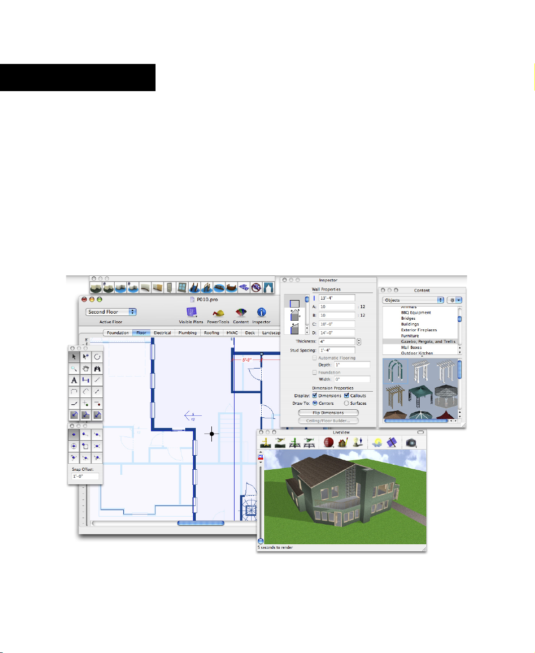
Workspace
The workspace is the hub of Punch! Home Design
Studio Pro. Not only do you create your drawing on
the workspace, but you can also control each of the
windows, your working floor, object elevation, and
other important facets of your design.
Elevation Slider
With Punch! Home Design Studio Pro’s Elevation
Slider you can easily move selected items
vertically off “ground level”. This feature makes
it a snap to make sure windows, doors, plants,
and so on, are in exactly the position you want.
Simply select the object or feature to be raised
and drag the slider. For more information, see
“Elevating your Selection”, on page 72.
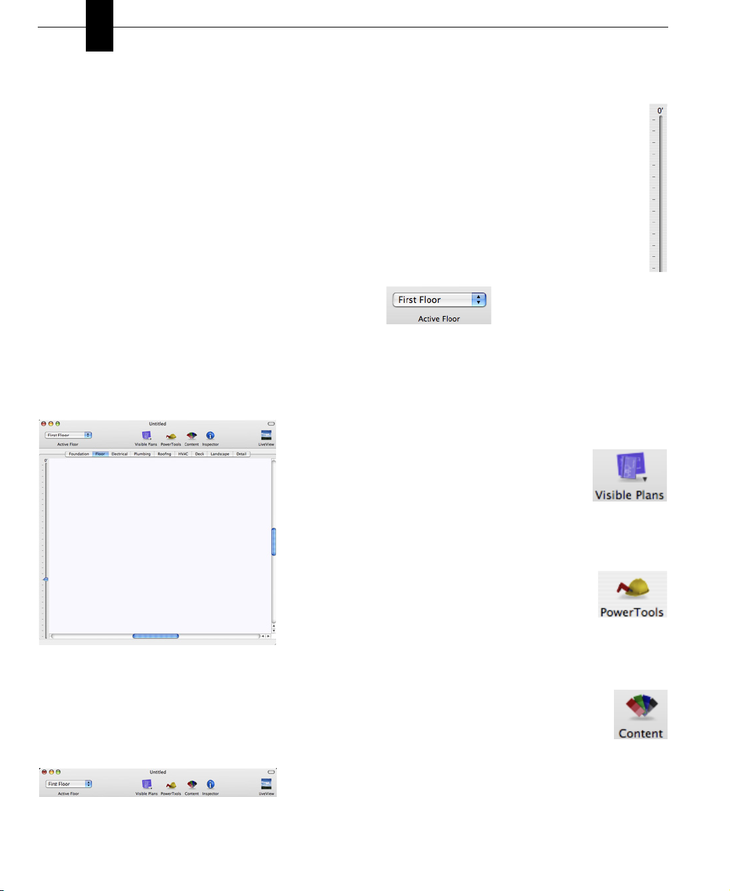
Active Floor Pop-up Menu
Use the Active Floor pop-up menu to switch the
current view, based on the number of floors in your
home plan. From the pop-up menu, choose the floor
you want to view and that floor appears on the
workspace.
Visible Plans
Click the Visible Plans button to
control which plans are visible on the
workspace. Visible plans appear with a
checkmark beside them in the pop-up menu.
Toolbar
On the toolbar, you can change your active floor,
control which plans are visible, access PowerTools,
and control windows.
6
PUNCH! Home Design Studio Pro User’s Guide
PowerTools
Click the PowerTools button to open
the PowerTool launcher. Choose the
PowerTool you want to use from the
launcher.
Content
Use the Content button to control the
Content window. If the window is open,
clicking the Content button closes the
window. Clicking the button, while the window is
closed, opens the window.
Page 11
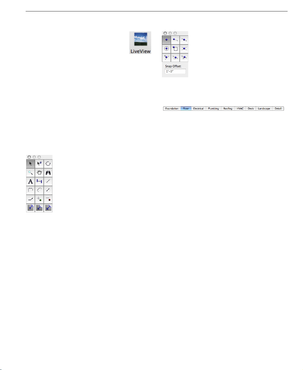
LiveView
Use the LiveView button to control the
LiveView window. If the window is closed,
clicking the LiveView button opens
LiveView. If LiveView is open, clicking the button
closes LiveView.
The LiveView window can be resized and moved
around your desktop so you can work in 2D while
viewing in 3D, or work in 3D. So when you’re ready to
add materials and colors to your dream home, you
can do it easily and accurately with LiveView.
LiveView
Plan Tabs
Editing Toolbox
The Editing Toolbox contains tools for editing your
design, such as the Selection Tool, Text Tool, and
dimensioning tools.
Snaps Toolbox
The Snaps Toolbox contains tools that you will begin
to find indispensable. Each snap has a very specific
function and will allow you to place walls, doors,
windows, and many other things exactly where you
want them - the first time!
see “Using Snaps”, which begins on page 31.
From placing a window exactly 6'4" from a corner to
placing a lamp exactly in the center of an end table,
you will begin to use Snaps in concert with almost
every other drawing tool in Punch! Home Design
Studio Pro.
For more information,
Punch! Home Design Studio Pro utilizes a collection
of layers, which are controlled using the plan tabs
located beneath the toolbar. Choosing a plan
accesses the tools associated with that plan, which
appear on the Plan Toolbox; for example, choosing
the Electrical tab accesses outlets, switches, and
ceiling fans, while choosing the Landscaping tab
accesses tools for edging, fencing, ground fill,
excavation, and so on. The Plan Toolbox contains
each plan’s tools, and appears independent of the
workspace, so you can move it to wherever you’d like.
When working with multiple plans, you can choose a
plan tab to work specifically on each plan. Only the
objects from the selected plan appear on the
workspace.
Once placed, each feature, such as a door, window,
plant, outlet, and so on, can be altered at any time.
Simply select the object and its properties appear
on the Inspector.
You can further customize which plan or combination
of plans you want to be active or visible, using the
Visible Plans button. In addition, you can make each
plan layer a different color, so you can tell, at a
glance, which layer a specific feature is on. You can
even move features to a different plan, when
necessary.
To select a plan tab
1 Choose the Selection Tool from the Editing
Toolbox.
2 Click the plan tab you want. The plan is selected
and its tools appear in the Plan Toolbox.
PUNCH! Home Design Studio Pro User’s Guide
7
Page 12
Chapter A Quick Tour
2
Plan Tools
The Plan Toolbar contains each plan’s tools. When
you click a plan tab, its tools appear in the toolbox.
Status Bar
The status bar is located in the lower left-hand
corner of the workspace and relays prompts,
program messages, and measurements. It is a good
place to look when you are holding the pointer over
certain buttons or menu items to find their
functions. Also, when positioning your pointer over
items in the Preview box, their names appear in the
status bar.
Inspector
The Inspector displays object properties, such as
size, shape, and other characteristics or properties
that control the appearance of the object. You can
easily modify features you have previously drawn by
selecting them and editing their properties, using
the Inspector.
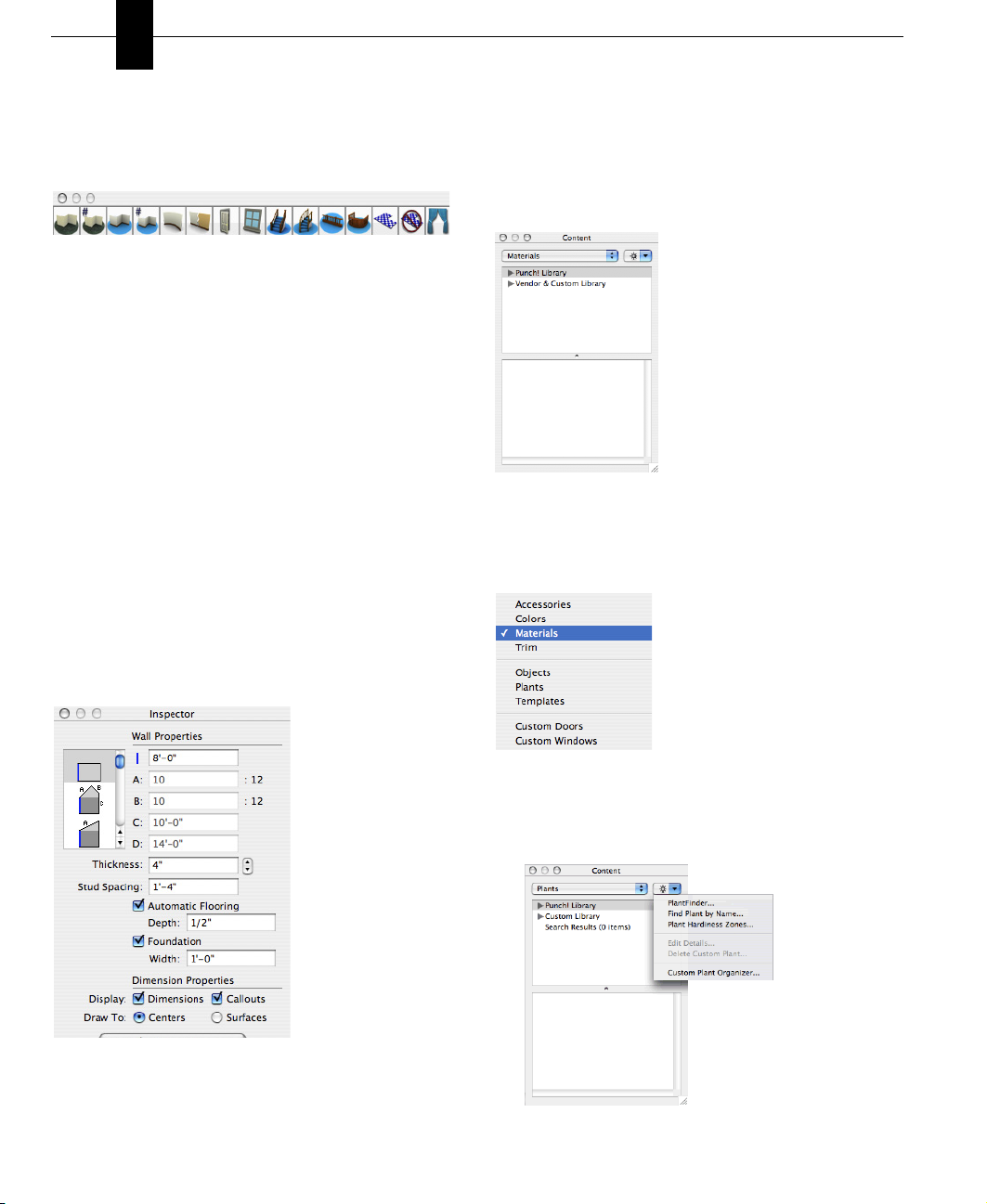
Content Window
You can drag objects, templates, materials, colors,
and so on, from the Content window onto your design.
The Content pop-up window contains a variety of
libraries:
Some libraries are contained within disclosure
triangles; click the triangle to view the libraries.
Once you choose a library, its contents appear in the
Preview box.
8
PUNCH! Home Design Studio Pro User’s Guide
The Objects and Plants libraries have a search
feature that searches the libraries, based on a name
or other criteria. To activate, click the Action popup menu to the right of the Content pop-up menu.
Page 13

Chapter 3
Finding Answers
Punch! Home Design Studio Pro is not just one software application, but several applications that can be
used together. Punch! provides you with a number of sources you can use to familiarize yourself with
these applications. When you have questions about a specific feature or procedure, this manual and Help,
that you can access from the program, provide a comprehensive guide to the tools in Punch! Home Design
Studio Pro. This chapter also discusses ways to access technical support and the Punch! web site.
PUNCH! Home Design Studio Pro User’s Guide
11
Page 14

Chapter Finding Answers
3
About This Guide
The text and graphics in this guide are tailored to
help you find the information you need quickly and
get the most out of Punch! Home Design Studio Pro.
Each section of this guide is divided into a series of
step-by-step instructions, making it easy for you to
scan a page to find exactly what you need. You can
also refer to the index for additional topics on the
same subject, if necessary.
NOTE: Instructions for installing and using your
Mac or Mac OS do not appear in this guide. If you’re
uncomfortable with your knowledge of Mac OS X or
with the concepts associated with your Mac, you
should review the documentation or online Help for
your Mac before attempting any serious work with
Punch! Home Design Studio Pro.
Basic Terms
The following is a list of terms used throughout this
guide. Take a moment to familiarize yourself with
the language used in this guide and to reinforce your
understanding of basic terminology.
Click - Pressing and releasing the mouse button once.
Double-click - Pressing and releasing the mouse
button twice.
Click and drag - Pressing the mouse button, holding it
down and moving the mouse, simultaneously.
Drag- Clicking to select an item, holding down the
mouse button, then dragging and releasing.
Scroll - Using the scroll bars on the sides of the
application window by clicking the slider box, holding
down the mouse button, and dragging.
Technical Support
Before contacting Punch! Technical Support, please
verify that the answer to your question is not
available from one of the following resources:
◆ Punch! Home Design Studio Pro User’s Guide
◆ Punch! Home Design Studio Pro Integrated
Help
◆ The Punch! Online Community is available at
http://forums.punchsoftware.com. At the
Online Community, users can post questions
and trade useful tips and tricks.
◆ The Customer Support Center is available at
http://punch.custhelp.com. At the Customer
Support Center you can register your
software, search the knowledgebase or ask a
question, if necessary.
The Customer Support Center can only answer
questions that are related to features of Punch!
Home Design Studio Pro. They cannot answer
specific questions about home building, local building
codes, and so on.
When contacting the Support Center, please provide
the following details:
◆ Serial Number; on the menu bar, choose
Home Design Studio > About Punch! Home
Design Studio Pro. Your serial number
appears on the dialog.
OR
Choose Home Design Studio > About Punch! Home
Design Studio Pro. Your Serial Number appears on
the window.
◆ Your computer’s operating system
◆ Make and model of your computer
Integrated Help
Punch! Home Design Studio Pro includes an extensive
integrated help system. This system includes all of
the information found in this
Studio Pro User’s Guide
To access the online help files
◆ Choose Help > Punch! Home Design Studio Pro
Help (or press Command+?).
12
PUNCH! Home Design Studio Pro User’s Guide
PUNCH! Home Design
.
After registering your program, you will receive free
technical support. When you call, you should be in
front of your computer, with the program running,
and have the above information handy. The technical
support contact information can be located at the
Customer Support Center punch.custhelp.com.
http://
Page 15

Chapter 4
Before You Draw
To get the most benefit from Punch! Home Design Studio Pro, you should take a minute to become
familiar with some of its basic concepts. This chapter describes a few settings you should know before
you begin your project.
With Home Design Studio Pro you can set a precise drawing scale, define units of measurement, and set
the reference grid. There are also many performance settings you can apply to optimize drawing speed
and 3D viewing.
PUNCH! Home Design Studio Pro User’s Guide
13
Page 16
Chapter Before You Draw
4
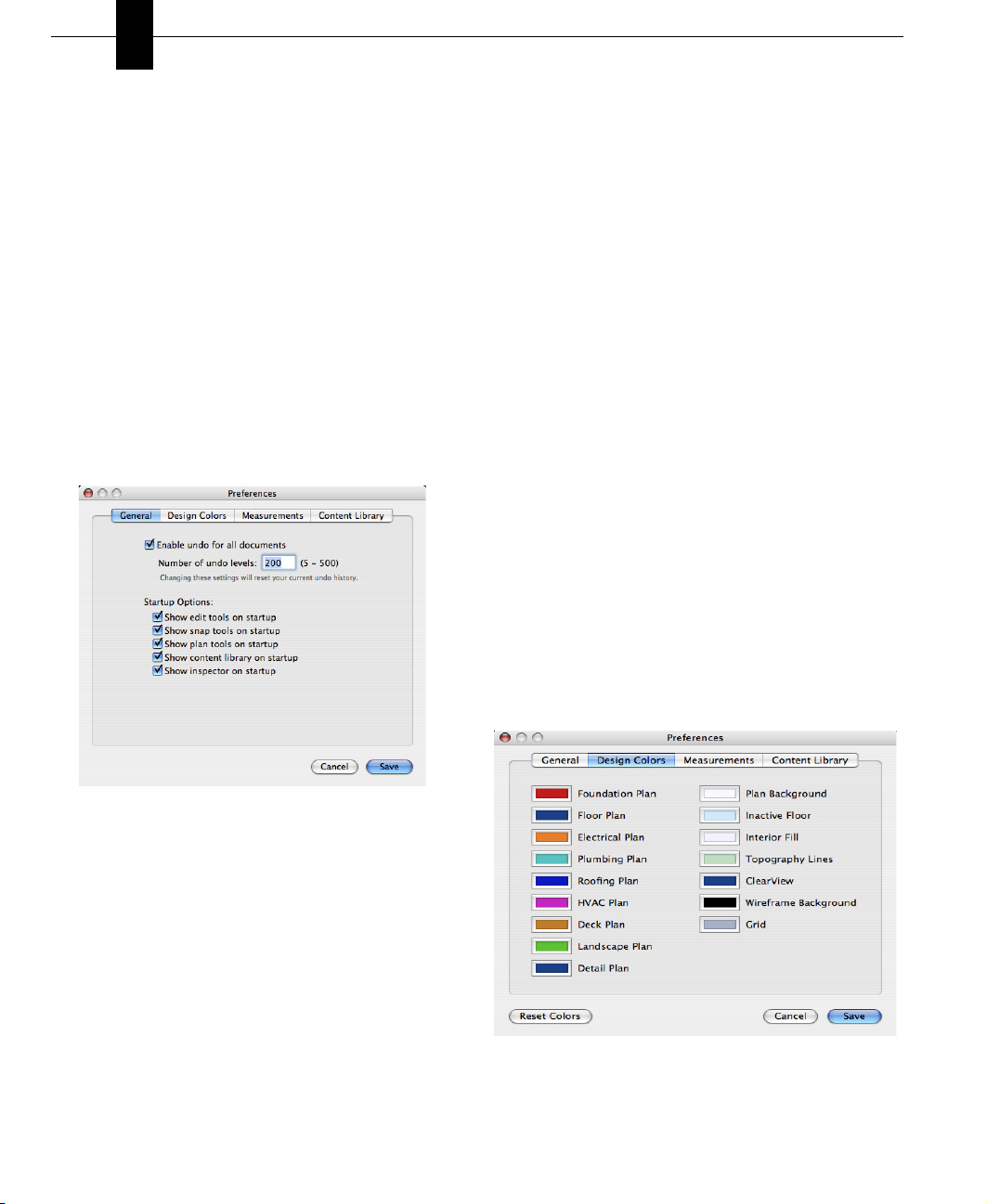
Setting Your Preferences
Your preferences control the overall look and way
your Punch! Home Design Studio operates. The
Preferences dialog contains four tabs. You can
control General Preferences, Design Colors,
Measurements, and the Content Library.
Measurement preferences can also be set by
choosing Design > Unit of Measure. However, using
the Preferences dialog, you can set your
measurement preferences while setting other
preferences.
To access preferences
◆ Choose Home Design Studio > Preferences (or
press Command-,). The Preferences dialog
appears.
4 When you open Punch! Home Design Studio Pro,
the toolboxes, Content Library, and Inspector
appear automatically. To disable any of these
features from appearing automatically upon
startup, deselect the corresponding checkbox
from the Startup Options on the General
Preferences dialog.
5 Click Save to save your preferences.
To set design colors preferences
When creating a design, organization is not only
important, but extremely helpful. To enhance
organization and efficiency, many of the features in
Punch! are color-coded so they are easily noticeable
on the workspace. For example, each of the floor
plans appear in a different color on the workspace.
The Foundation plan appears in red, while the Floor
plan is blue, and Electrical components appear in
orange. So, at a glance you can distinguish one floor
plan from another. Each of these colors can be
customized.
Along with the plans, the plan background, inactive
floors, interior fill, topography lines, ClearView,
Wireframe Background, and grid colors can be
customized.
1 Choose Home Design Studio > Preferences (or
press Command-,) and click the Design Colors
tab. The Preferences dialog appears.
To set general preferences
1 Choose Home Design Studio > Preferences (or
press Command-,). The Preferences dialog
appears.
2 Undo is automatically enabled for all documents
in Punch! To disable the Undo feature, deselect
the “Enable undo for all documents” checkbox.
3 When the Undo feature is enabled, you can
“undo” anywhere between 5 and 500 of your
previous actions. The undo level is set to 200.
Enter the number of undo levels you want in the
“Number of undo levels” field.
14
PUNCH! Home Design Studio Pro User’s Guide
2 Each customizable feature appears with a color
well beside it. Click the color well to change the
color. The Colors window appears. For example, if
Page 17
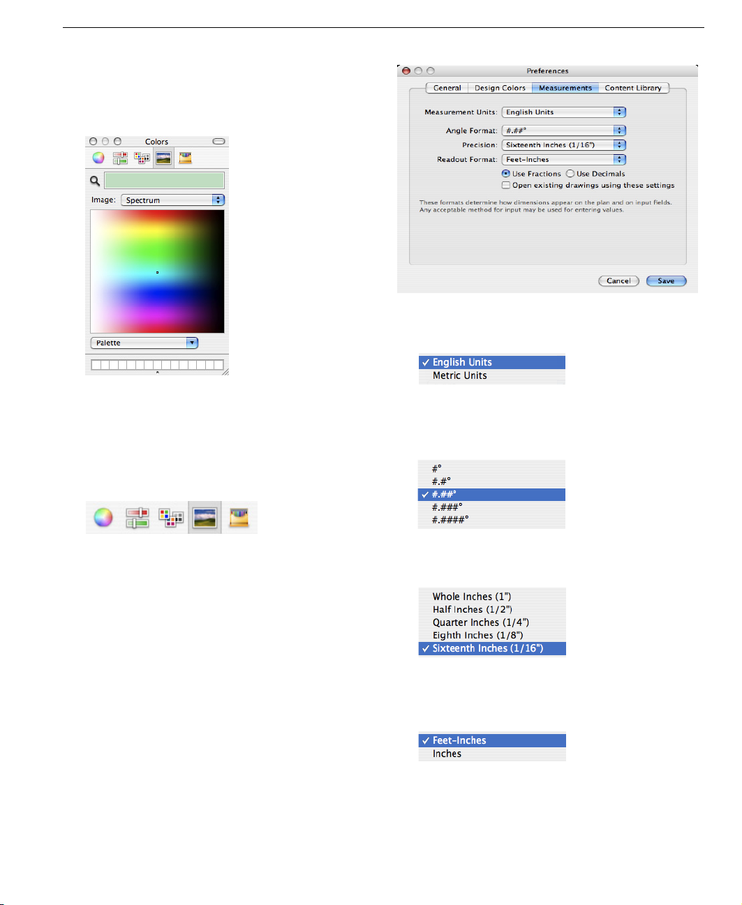
you want to change the color Topography Lines
appear on the workspace, click the Topography
Lines color well. The current color appears in the
Colors window, as seen below.
Setting Your Preferences
2 Click the Measurement Units pop-up menu and
choose which measurement unit you want to use.
There a five models for choosing colors:
✘ Color Wheel
✘ Colors Sliders
✘ Color Palettes
✘ Image Palettes
✘ Crayons
3 Select the model you want to use and choose a
new color then close the window. Customized
colors appear with an earmark in the top right
corner of the color well.
4 Click Save to save your preferences.
To set measurement preferences
You can select either English or Metric Units of
measurement for your design, as well as the number
of decimal places angles appear, the precision of
measurements, and the format in which
measurements appear.
1 Choose Home Design Studio Pro > Preferences (or
press Command-,) and click the Measurements
tab. The Preferences dialog appears.
3 Click the Angle Format pop-up menu and choose
how many decimal places you want to appear when
an angle is displayed.
4 Click the Precision pop-up menu and choose how
precise you want measurements to appear.
5 Click the Readout Format pop-up menu and
choose how you want measurements to appear in
Feet-Inches format, or just Inches.
6 By default, measurements appear as fractions on
the workspace. If you want measurements to
appear with decimals, click the Use Decimals
radio button.
PUNCH! Home Design Studio Pro User’s Guide
15
Page 18
Chapter Before You Draw
4
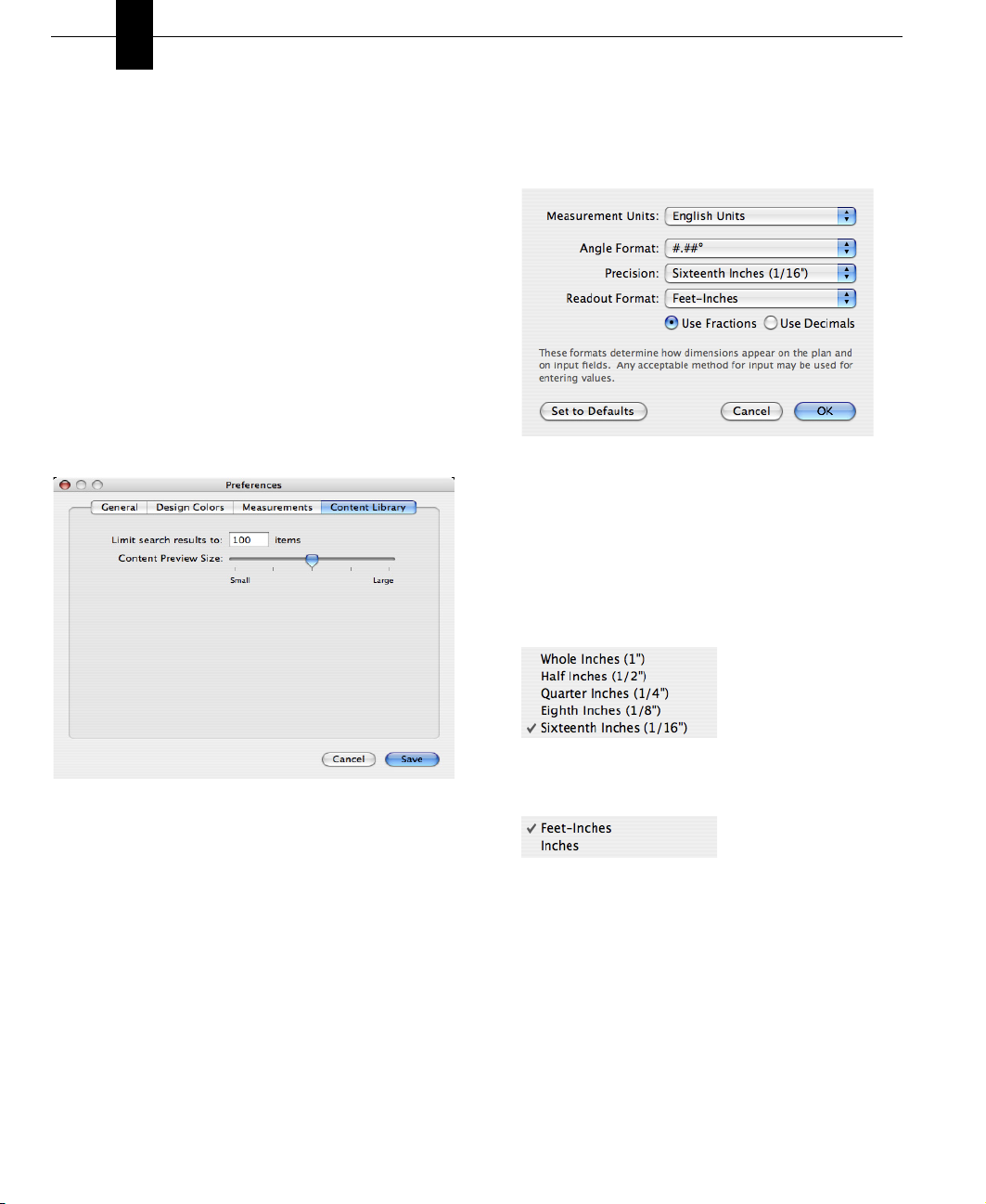
7 Click the “Open existing drawings using these
settings” checkbox to automatically apply the
Measurement preferences to existing drawings.
Otherwise, preferences only apply to drawings
created after the preferences have been set.
8 Click Save to save your preferences.
To set content library preferences
The Content Library displays colors, materials, and
2D and 3D objects. You can limit the number of
results that appear when searching for specific
items, as well as control the size of items that
appear in the Preview Box.
1 Choose Home Design Studio Pro > Preferences (or
press Command-,) and click the Content Library
tab. The Preferences dialog appears.
To use English measurements
1 Choose Design > Unit of Measure. The dialog
appears.
2 From the Measurement Units pop-up menu,
choose English Units.
3 (optional) From the Angle Format pop-up menu,
choose the number of decimal points you want to
use.
4 (optional) From the Precision pop-up menu,
choose how precise you want your measurements
to be.
2 Enter the number of search results you want to
appear in the Limit search results to field.
3 Drag the Content Preview Size slider to set the
size of the images that appear in the Preview
Box.
4 Click Save to save your preferences.
Setting the Units of Measurement
You can set units of measurement by selecting
either English or Metric measurements. You can also
set the default measurements and options to be
applied when any previously-drawn design is opened.
16
PUNCH! Home Design Studio Pro User’s Guide
5 (optional) From the Readout Format pop-up menu,
choose the format you want.
6 Click OK. The unit of measurement and options
you selected are applied.
To use Metric measurements
1 Choose Design > Unit of Measure. The
Measurement Units dialog appears.
2 From the Measurement Units pop-up menu
choose Metric Units. The dialog appears.
Page 19
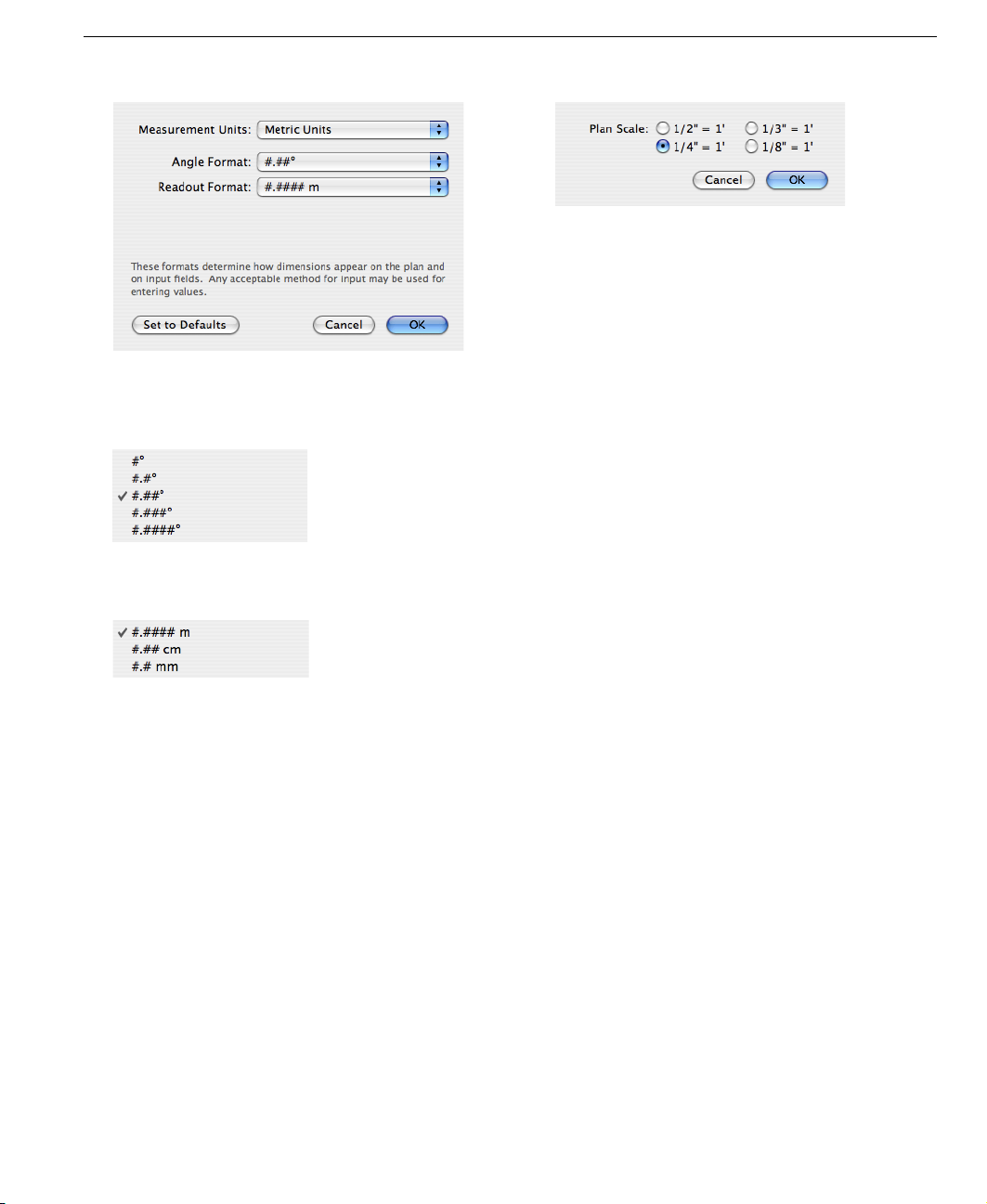
3 (optional) From the Angle Format pop-up menu,
choose the number of decimal points you want to
use.
Setting the Scale
2 Click a new scale setting, then click OK. The new
scale is applied to your plan drawing.
Defining Your Lot Size and Topography
Use the Topography Designer PowerTool to define
lot size and all topography.
For more information, see “Topography Designer”,
which begins on page 87.
NOTE: To draw curved property lines, use the
Curve Tool on the Detail Tab, then
Details to Intelligent Features”, which begins on
page 195.
see “Converting
4 (optional) From the Readout Format pop-up menu,
choose the format you want.
5 Click OK. The unit of measurement and options
you selected are applied.
NOTE: To restore the factory defaults, click Set
to Default.
Setting the Scale
Scale is the ratio between real-world size of objects
and items in your drawing and their size when
printed. The default drawing scale is 1/4" = 1',
meaning that 1/4" on your drawing plan equals one
foot in real-world size. You can customize scale
settings at any time to suit your needs, as well as
print your drawing to scale.
To set the drawing scale
1 Choose Design > Plan Scale. The Plan Scale dialog
appears.
Speed Tips
You can “speed up” Home Design Studio Pro by
changing some of the program's settings.
◆ Close the LiveView window when you are not
working in 3D. No 3D calculations are
performed when the LiveView window is
closed.
◆ Turn off shadows. For more information, see
“Adding Lighting and Shadows”, which begins
on page 46.
◆ Choose LiveView > Render Options and the
dialog appears. From the Rendering &
Navigation tab, deselect Render objects you
do not need to view. This will help speed up
the rendering process. Click the Geometry
Quality tab and drag the sliders to lower the
render quality of 3D objects.
PUNCH! Home Design Studio Pro User’s Guide
17
Page 20

Chapter Before You Draw
4
Display Settings
Home Design Studio Pro is designed to run
effectively, based on the system requirements
printed on the software packaging. However, there
are some specific settings you can select to obtain
the best display possible.
To adjust your display settings
1 From the Apple menu, choose System
Preferences. The System Preferences dialog
appears.
2 Click the Displays icon and choose the Resolution
you want. The lower your resolution, the larger
items appear.
3 From the Colors pop-up menu, choose the number
of colors you want your computer to use for
display. Selecting the highest Colors setting will
show a more realistic view of your design.
4 Click the Color tab and choose the Display Profile
you want.
18
PUNCH! Home Design Studio Pro User’s Guide
Page 21

Part 2
PUNCH! SOFTWARE PRIMER
Chapter 5: Drawing 2D Entities . . . . . . . . . . . . . . . . 21
Chapter 6: Using Snaps . . . . . . . . . . . . . . . . . . . . . . . 31
Chapter 7: Viewing in 2D & 3D . . . . . . . . . . . . . . . . . 37
Chapter 8: Adding 3D Content . . . . . . . . . . . . . . . . . 51
Chapter 9: Rearranging Entities . . . . . . . . . . . . . . . . 69
Chapter 10: Saving, Sharing & Printing . . . . . . . . . . 77
Page 22

Page 23

Chapter 5
Drawing 2D Entities
This chapter contains concepts and procedures that you will need throughout your design process.
Many 2D features are drawn in the same way throughout Punch! Home Design Studio Pro and the
PowerTools that are included with it. The buttons may differ slightly, but the process is the same.
PUNCH! Home Design Studio Pro User’s Guide
21
Page 24
Chapter Drawing 2D Entities
5
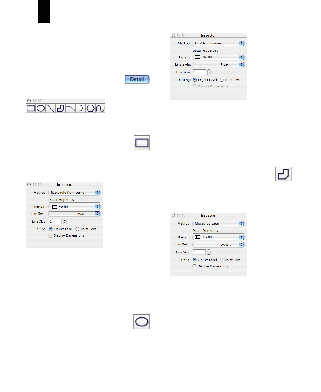
Drawing Shapes
Many features are drawn in the same way
throughout Punch! Home Design Studio Pro and the
PowerTools that are a part of it. The buttons may
differ slightly, but the process is the same.
To see the shapes available in Punch!
Home Design Studio, click the Detail tab.
The shapes appear in the Detail Plan toolbar.
To draw rectangles and squares
1 From the Detail Plan Toolbox, choose the
Rectangle Tool. A crosshair appears, as
you move your cursor over the workspace.
2 On the Inspector, click the Method pop-up menu
and choose how you want to draw your rectangle
or square.
From the Inspector, you can also choose the
Pattern, Line Style, and Line Size before or
after you draw.
3 On the workspace, drag the crosshair to draw
the shape. Notice its dimensions appear, as you
draw.
To draw a polygon
1 From the Detail Plan Toolbox, choose
the Polygon Tool. A crosshair appears,
as you move your cursor over the
workspace.
2 On the Inspector, click the Method pop-up menu
and choose how you want to draw your polygon.
3 From the Inspector, you can also choose the
Pattern, Line Style, and Line Size before or
after you draw.
4 On the workspace, drag the crosshair to draw
the shape. Notice its dimensions appear, as you
draw.
To draw circles and ovals
1 From the Detail Plan Toolbox, choose the
Circle/Oval Tool. A crosshair appears, as
you move your cursor over the
workspace.
2 On the Inspector, click the Method pop-up menu
and choose how you want to draw your circle or
oval.
22
PUNCH! Home Design Studio Pro User’s Guide
From the Inspector, you can also choose the
Pattern, Line Style, and Line Size before or
after you draw.
3 To draw a polygon, click on the workspace to set
the first point.
4 Drag the crosshair to extend the rubber-band
line and click to place the next point. Notice its
dimensions appear, as you draw.
5 Continue to drag the rubber-band line and click
to place points to define your shape.
Page 25
6 To finish the shape, double-click on the first
point you placed or Ctrl-click and Punch!
automatically encloses the shape for you.
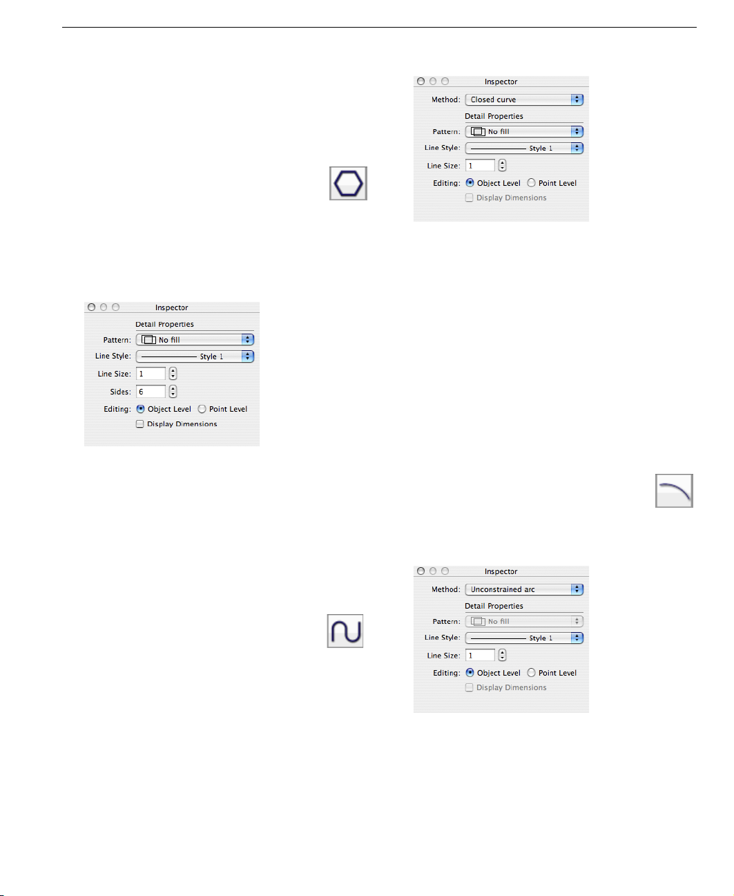
To draw a multigon
1 From the Detail Plan Toolbox, click the
Multigon Tool. A crosshair appears, as
you move your cursor over the
workspace.
2 On the Inspector, click the Sides control to set
the number of sides, or enter the number of
sides you want in the Sides text field and press
the Enter key.
Drawing Shapes
From the Inspector window, you can also choose
the Pattern, Line Style, and Line Size before or
after you draw.
3 To draw a curve, click on the workspace to place
the first point and drag the crosshair to extend
the rubber-band line.
4 Click to set the next point. Continue to drag the
rubber-band line and click points to define the
curve.
5 To finish the shape, double-click on the first
point you placed or press Ctrl-click and Punch!
automatically closes the shape for you.
From the Inspector window, you can also choose
the Pattern, Line Style, and Line Size before or
after you draw.
3 On the workspace, drag the crosshair to draw
the shape. A rubber-band shape appears and
follows, as you move the crosshair. Notice its
dimensions appear, as you draw.
To draw a curve
1 From the Detail Plans Toolbox, click the
Curve Tool. A crosshair appears, as you
move your cursor over the workspace.
2 On the Inspector, click the Method pop-up menu
and choose how you want to draw your curve.
To draw an arc
1 From the Detail Plan Toolbox, click the
Arc Tool. A crosshair appears, as you
move your cursor over the workspace.
2 On the Inspector, click the Method pop-up menu
and choose how you want to draw your curve.
From the Inspector window, you can also choose
the Pattern, Line Style, and Line Size before or
after you draw.
3 On the workspace, drag the crosshair to extend
the rubber-band line to the length you want.
Notice its dimensions appear, as you draw.
PUNCH! Home Design Studio Pro User’s Guide
23
Page 26
Chapter Drawing 2D Entities
5
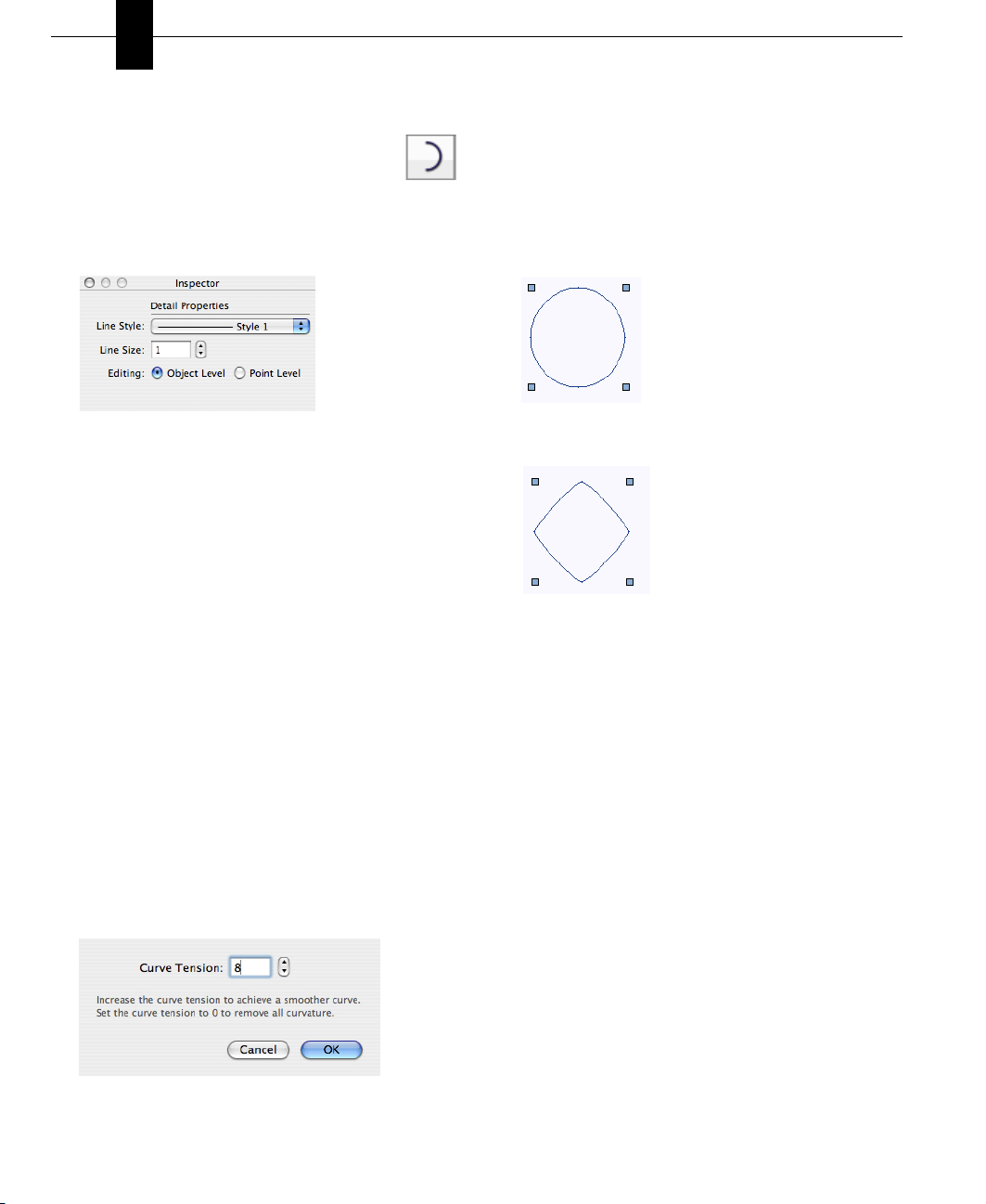
To draw a circular arc
1 From the Detail Plan Toolbox, click the
Circular Arc Tool. A crosshair appears,
as you move your cursor over the
workspace.
2 On the Inspector, you can choose the Line Style
and Line Size before or after you draw.
3 On the workspace, drag the crosshair to set the
radius of the arc. Release to place.
4 Drag the crosshair to set the swing angle of the
arc. Click to place.
Changing Curve Tension
To further customize the look of the shapes drawn
with any of the arc or curve tools, you have control
over the degree of curve assigned to them. With the
Straighten feature, it is easy to create angular
shapes and, with Curve Tension, you can change the
appearance. Curve Tension is measured between 1
and 10. Specifying 1 in the dialog results in very
little tension being applied, while specifying 10
causes a slightly-exaggerated curve.
To change curve tension
1 Select an object. Its properties appear on the
Inspector.
2 On the Inspector, click the Adjust Curvature
button. The Curve Tension dialog appears.
3 Enter the amount of tension you want, or use the
stepper controls to increase or decrease the
tension.
4 Click OK. The Curve Tension you set is applied.
Examples:
Default Curve Tension (8):
Curve Tension set at 2:
To remove curve tension
1 Select the curved object you want to straighten.
2 On the Inspector, click the Straighten Curve
button.
Using the Grid
With Punch! Home Design Studio Pro you can set
specific grid properties that aid in drawing your
home plan. You can set points, based on the
reference grid, which is useful when you want to
make sure that certain points are specified
precisely.
Grid settings have a direct impact on the ease of
aligning objects, snapping objects to the grid, and so
on. When using the Snap to Grid feature, items that
are dragged and dropped on the design window are
automatically snapped, or placed, to align with the
current grid. By default, Snap to Grid is on.
You can customize grid settings by selecting grid
spacing, grid style, and hiding or displaying.
24
PUNCH! Home Design Studio Pro User’s Guide
Page 27
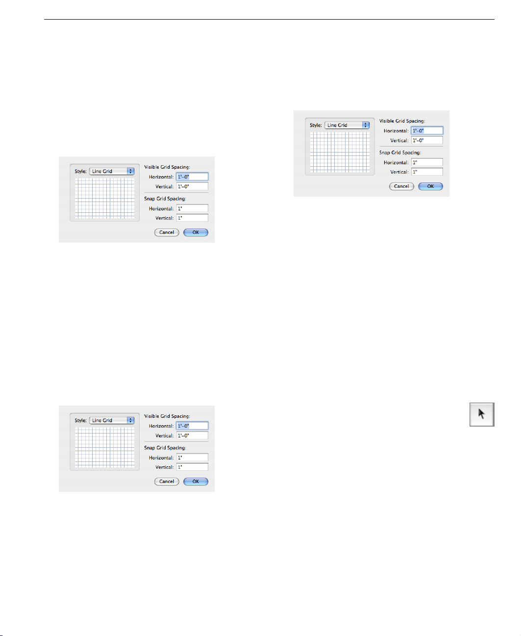
Using the Grid
Grid properties can also be set by pressing Ctrl-click
on the workspace and choosing Grid Properties from
the shortcut menu.
To change the grid style
1 Choose View > Grid Properties or Ctrl-click on the
workspace and choose Grid Properties. The Grid
Properties dialog appears.
2 From the Style pop-up menu, select which style
grid you want.
3 Click OK to apply the style to the grid.
Grid Dots/Lines can be set to as low as 1 inch
(English), 0.02 m (Metric), and still be visible.
Grid Dots/Lines can be set as high as 500 inches
(English), 12.70 m (Metric).
To select grid spacing
1 Choose View > Grid Properties or Ctrl-click on the
workspace and choose Grid Properties. The Grid
Properties dialog appears.
2 Enter new values in the Horizontal and Vertical
Visible Grid Spacing text fields.
3 Click OK to accept the new values. The grid
appears with the new values applied to it.
To define Snap to Grid settings
1 Choose View > Grid Properties, or Ctrl-click on
the workspace and choose Grid Properties. The
Grid Properties dialog appears.
2 Enter new values in the Horizontal and Vertical
Snap Grid Spacing text fields.
3 Click OK to accept the new values. Items you
draw or drag onto the design window now snap to
the measurements you defined.
NOTE: Initially, the grid is set at 12 inches, making
it easy to visualize each plan square as exactly one
square foot, but can be customized to meet your
particular design needs.
NOTE: Snap settings can be set as low as 0.0625
(1/16) inch (English), 0.01 meter (1 cm) (Metric), and
still show visible movement along the grid. Snap
settings can be set as high as 500 inches (English),
12.70 meter (Metric).
To move objects/features along the grid
1 From the Editing Toolbox, click the
Selection Tool.
2 Select the object or feature you want to
move.
3 Using the arrow keys on your keyboard, move the
object or feature into position.
Each time you press an arrow key, the object or
feature moves one increment that you have
defined on the Grid Properties dialog.
To turn off Snap to Grid
◆ Choose View > Snap to Grid, or Ctrl-click on
the workspace and deselect Snap to Grid. The
feature is disabled. To enable Snap to Grid,
simply reselect the menu item.
PUNCH! Home Design Studio Pro User’s Guide
25
Page 28
Chapter Drawing 2D Entities
5
To display the grid
◆ Choose View > Show Grid, or Ctrl-click on the
workspace and choose Show Grid. The grid
appears on the workspace.
Dimensioning
Punch! Home Design Studio Pro automatically
displays dimensions, as you draw, making it easy to
precisely place walls, doors, and other objects in
your plan drawing. You have the option of turning off
automatic dimensioning, if you don’t want it displayed
on the workspace, as you draw.
To use the wall-spacing dimension tool
1 From the Editing Toolbox, click the
Dimension Wall Spacing Tool.
2 On the workspace, click a wall to define
the starting point and drag the crosshair to the
second wall.
3 Release the mouse button to set the
measurement.
To use the zero-offset dimension tool
1 From the Editing Toolbox, click the Zero-
offset Dimension Tool.
2 On the workspace, click a wall to define
the starting point and drag the crosshair to the
desired length.
3 Release the mouse button to set the
measurement.
To turn off automatic dimensioning
◆ Choose View > Hide Automatic Dimensions or
Ctrl-click on the workspace and choose Hide
Automatic Dimensions.
To hide window and door dimensions
◆ Choose View > Hide Window & Door Callouts,
or Ctrl-click on the workspace and choose
Hide Window & Door Callouts.
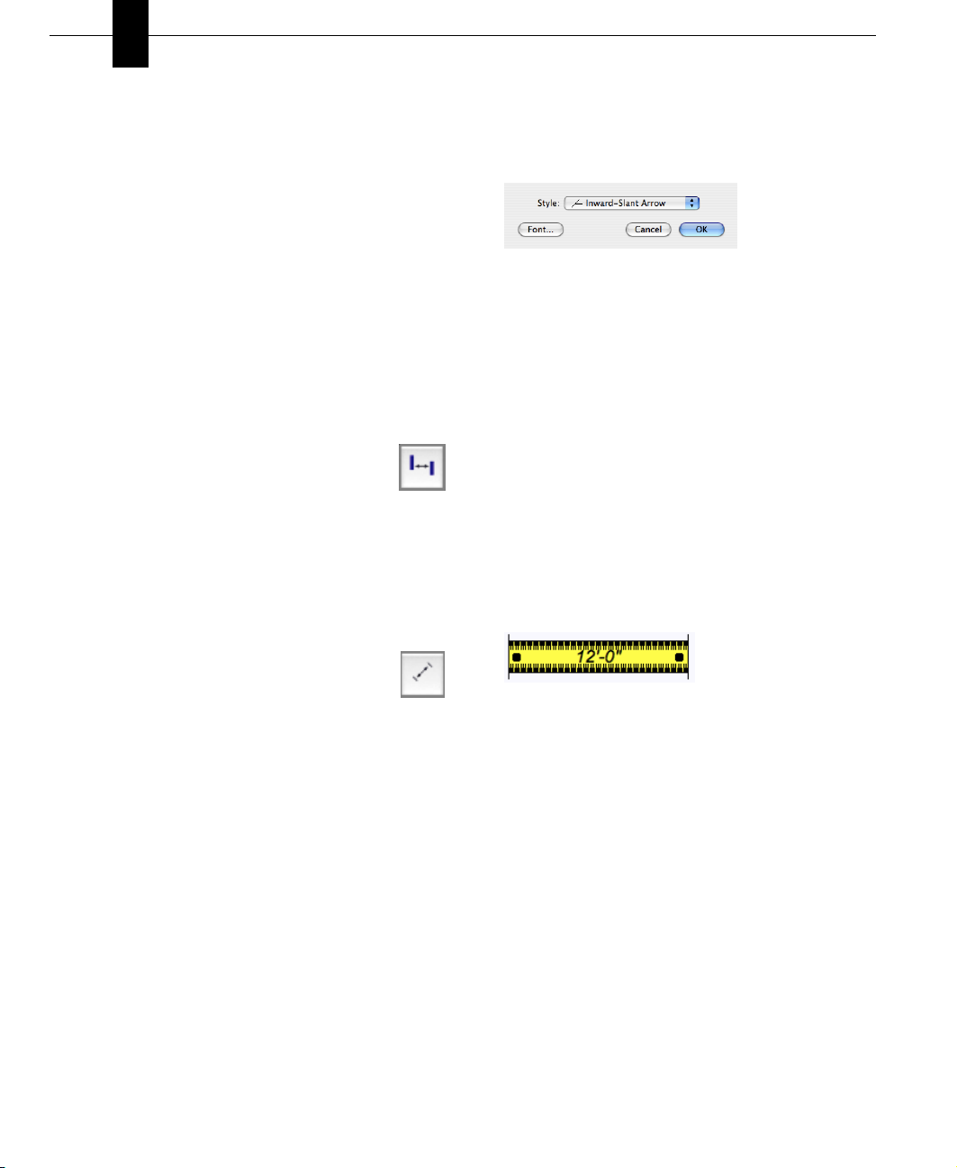
To change the endpoint style
1 Choose View > Dimension Properties. The dialog
appears.
2 From the Style pop-up menu, choose an endpoint
style and click OK. The new style is applied to all
endpoints in your design.
Using the Virtual Ruler
The Virtual Ruler is a handy feature for measuring
items in your home plan that are not automatically
dimensioned. You can show the ruler at any time,
leaving it active, or hide it from view with one mouse
click. The Virtual Ruler is an easy way to measure at
an angle, too.
To measure using the Virtual Ruler
1 Choose View > Show Virtual Ruler, or Ctrl-click on
the workspace and choose Show Virtual Ruler.
2 Drag a black circle on the ruler in the direction
you want to measure. The measurement appears
in the center of the Virtual Ruler.
3 To move the Virtual Ruler around the workspace,
simply drag the center of the ruler to a new
location.
NOTE: The Virtual Ruler appears in the center of
the drawing space.
To hide the Virtual Ruler
◆ Choose View > Hide Virtual Ruler, or Ctrl-click
on the workspace and choose Hide Virtual
Ruler to hide the ruler.
26
PUNCH! Home Design Studio Pro User’s Guide
Page 29
Calculating Square Footage
Punch! Home Design Studio Pro can automatically
calculate square footage of each floor of your home
plan. This feature makes it easy to figure how much
carpet you’ll need to cover the first floor, for
instance, or simply estimate your overall home size.
If square footage is incorrect, check to make sure
the exterior perimeter is intact.
information, see “Defining the Foundation
Perimeter”, which begins on page 98.
For more
To calculate floor square footage
◆ Choose Design > Calculate Area and, from the
submenu, choose which floor’s area you want
to calculate. The square footage appears in
the Status Bar in the lower left-hand corner.
NOTE: The square footage calculation is based on
wall centerline measurements.
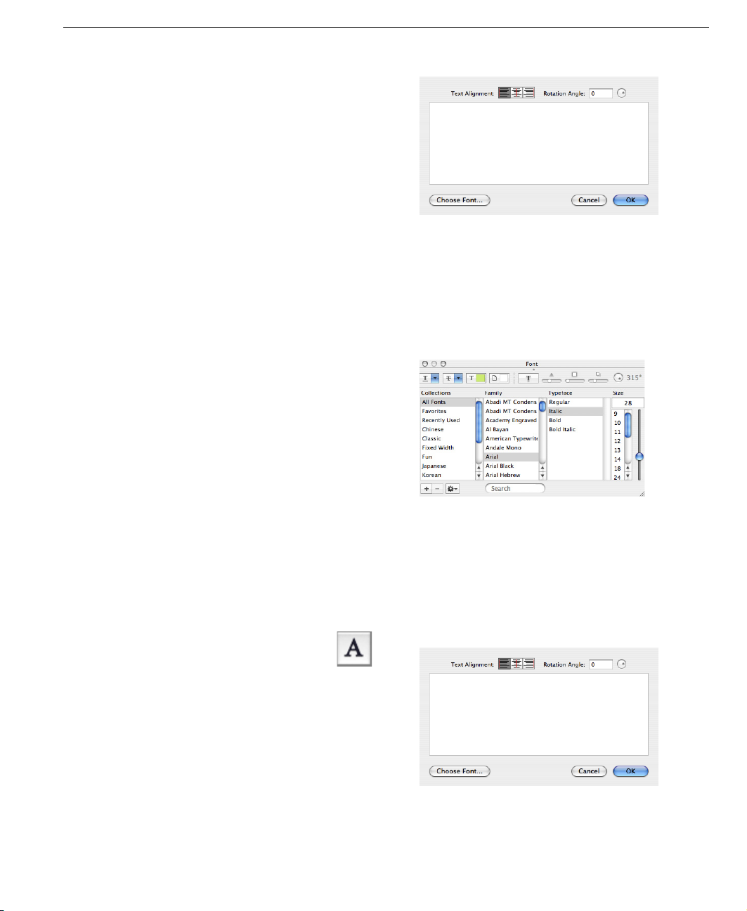
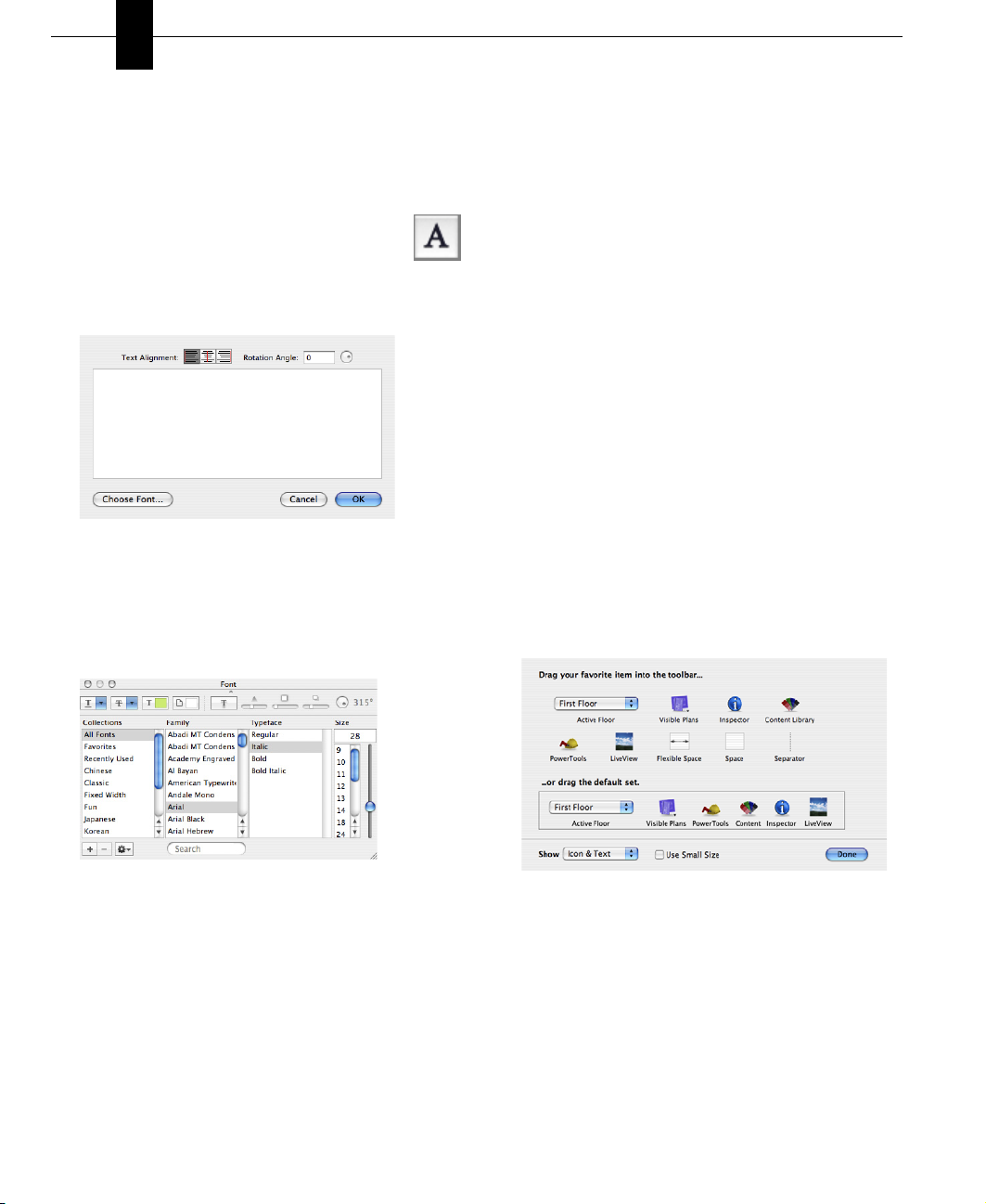
Adding Text
You can use text to add information to your drawing.
For example, you might add text to annotate rooms,
a home address, the date the drawing was created,
or a specific feature in your plan. Punch! Home
Design Studio Pro gives you the flexibility to place
text anywhere on your plan drawing, using different
formatting techniques for each text instance. Text
you place in your drawing appears on all 2D printed
output.
To place text in your drawing
1 From the Editing Toolbar, click the Text
Tool. A crosshair appears, as you move
your cursor over the workspace.
2 Position the crosshair where you want the text
to appear and click. A text dialog appears.
Calculating Square Footage
3 Enter text in the text field.
Enter the angle you want the text to appear in
the Rotation Angle field, or drag the rotation dial
to set the rotation.
Click the Choose Font button. The Text dialog
appears. Choose the Font, Style, and Size, then
close the dialog.
4 Click OK to place the text on the workspace.
To change alignment of multi-line text
1 From the Editing Toolbox, click the Selection
Tool, then select the text you want to change.
2 Double-click the selected text. The dialog
appears.
3 Choose the Text Alignment you want.
4 Click OK to update the text.
PUNCH! Home Design Studio Pro User’s Guide
27
Page 30
Chapter Drawing 2D Entities
5
To edit text
◆ Double-click the text you want to edit.
To place text at an angle
1 From the Editing Toolbox, click the Text
Tool. A crosshair appears, as you move
your cursor over the workspace.
2 Position the crosshair where you want the text
to appear and click. A text field appears.
3 Enter the angle you want the text to appear in
the Rotation Angle text field, or drag the
rotation dial to set the rotation.
4 (optional) Click the Choose Font button. The Font
dialog box appears. Choose the Font, Style, and
Size you want.
3 To change the text font, click the Choose Font
button and change the font, style, and size.
4 Click the Text Alignment you want, to change the
text alignment.
5 Enter the angle you want the text to appear, in
the Rotation Angle text field, or drag the
rotation dial to set the rotation.
6 Click OK to update the text.
Controlling the Toolbar Appearance
You can control your toolbar’s appearance to
increase efficiency and workability. Punch! Home
Design Studio Pro allows you to control which items
appear on your toolbar, as well as how they appear;
just an icon, icon with text, just text. You can also
decrease the size of the items and hide the toolbar
completely, if you wish.
To customize items in your toolbar
1 From the View menu, choose Customize Toolbar,
or Ctrl-click on the toolbar and choose Customize
Toolbar, from the shortcut menu. The toolbar
customization window appears.
Click the red button in the top left corner to
close the dialog.
5 Enter the annotation in the text field.
6 Click OK to place the text.
To change formatting of existing text
1 Select the text you want to change.
2 Double-click the selected text. The text dialog
appears.
28
PUNCH! Home Design Studio Pro User’s Guide
2 To add an item, or items, to your toolbar, drag an
item from the customization window to the
toolbar.
3 To remove an item, or items, from your toolbar,
drag an item from the toolbar to the
customization window.
OR
◆ Ctrl-click on the item you want to remove and
choose Remove Item from the shortcut menu.
Page 31

To restore the default toolbar
1 From the View menu, choose Customize Toolbar,
or Ctrl-click on the toolbar and choose Customize
Toolbar, from the shortcut menu. The toolbar
customization window appears.
2 Drag the default toolset onto the toolbar.
To customize toolbar item appearance
1 From the View menu, choose Customize Toolbar,
or Ctrl-click on the toolbar and choose Customize
Toolbar, from the shortcut menu. The toolbar
customization window appears.
2 From the Show pop-up menu, choose how you
want items to appear.
3 (optional) Select the “Use Small Size” checkbox
to decrease the size of the toolbar items.
4 Click Done to accept the changes.
OR
◆ Ctrl-click on the toolbar and choose which
display you want, from the shortcut menu.
Controlling the Toolbar Appearance
To hide the toolbar
◆ Choose View > Hide Toolbar.
PUNCH! Home Design Studio Pro User’s Guide
29
Page 32

Chapter Drawing 2D Entities
5
30
PUNCH! Home Design Studio Pro User’s Guide
Page 33

Chapter 6
Using Snaps
The powerful Snaps Toolbar makes precision placement easier. On the Snaps Toolbar, there are a wide
variety of precision drawing aids that will help in exact placement of walls, doors, windows, and so on.
Often, drawing a plan to scale is not enough to convey precise measurements. In such cases, you must
notate the measurements, using manual dimension notes. Punch! Home Design Studio Pro, by default,
automatically displays dimensions, as you draw. This makes it easy to create accurate drawings from the
start.
PUNCH! Home Design Studio Pro User’s Guide
31
Page 34

Chapter Using Snaps
6
Snap Basics
With Snaps, you can define exactly what distance
interior walls are placed from other walls or begin
exactly at the end of the wall, when drawing a roof
section.
The following examples show a few ways that Snaps
will help you during the design process; each Snap
tool works in concert with many other tools in Punch!
Home Design Studio Pro. Once you’ve selected a
Snap tool, you can quickly select another by pressing
the Tab key.
Show/hide the Snap Tools
◆ The Snaps toolbar appears by
default. To hide the window,
choose Window > Hide Snap
Tools.
◆ To show the Snap tools, choose
Window > Show Snap Tools. The
Snaps toolbar appears.
NOTE: Each Snap tool defaults back to Snap
Anywhere after it is used. To lock the selected tool,
double-click the Snap tool on the Snaps toolbar. If
you have locked a Snap tool and press the Tab key to
activate another tool, it will also be locked as active.
To unlock it, click Snap Anywhere.
NOTE: Walls are drawn from a centerline. When
moving or otherwise manipulating them, you are
always working from the centerline and snapping to
them will do the same.
To snap a wall from the end of another wall
1 From the Floor Plan toolbar, click the
Interior Wall Tool.
2 From the Snaps toolbar, click the Snap to
Endpoint Tool.
3 Position the crosshair along an existing
wall on the workspace.
4 Drag the crosshair to extend the rubber-band
line to the length you want. The wall “snaps to”
the nearest endpoint. Notice that the wall
follows the crosshair and automatically displays
the wall length.
5 Release to place the wall.
To snap a roof
1 From the Roofing Plan toolbar, click one of the
Roof tools. The Roof Properties appear on the
Inspector.
2 From the Snaps toolbar, click the Snap to
Endpoint Tool, or press the Tab key.
3 Hold down the mouse button and drag,
until the cursor touches another wall.
32
PUNCH! Home Design Studio Pro User’s Guide
Page 35

Snap to Segment Centerpoint
4 (optional) Press Tab to re-activate the Snap to
Endpoint Tool. The roof will automatically extend
to cover the entire perimeter.
5 Release the mouse button.
Snap to Segment Centerpoint
Snap to Segment Centerpoint will be useful when
drawing walls, placing doors or windows, and so on.
You can move through the Snaps toolbar with the
Tab key. Each time you press Tab, the next Snap
tool is activated; Shift-Tab reverses the process.
4 Drag the crosshair to extend the wall to the
length you want.
NOTE: Each Snap tool defaults back to Snap
Anywhere after it is used. To lock the selected tool,
double-click the Snap tool on the Snaps toolbar. If
you have locked a Snap tool and press the Tab key to
activate another tool, it will also be locked as active.
To unlock it, click Snap Anywhere.
To snap a window in the center of a wall
1 From the Floor Plan toolbar, click the Window
Tool. The Window Properties appear on the
Inspector.
2 From the Snaps toolbar, click the Snap to
Segment Center Tool or press the Tab
key to move through the tools.
3 On the workspace, position the crosshair along a
wall and click. The window will “snap to” the
centerpoint of the wall.
To snap a wall from the center of another wall
1 From the Floor Plan toolbar, click the
Interior Wall Tool.
2 From the Snaps toolbar, click the Snap to
Segment Center Tool, or press the Tab
key to move through the tools on the
Snaps toolbar.
3 On the workspace, position the crosshair along an
existing wall and drag to extend the rubber-band
line. The wall automatically “snaps to” the center
of the existing wall.
4 (optional) Customize the window properties, as
shown in the section “To add a window” on page
115.
Snap to Object Center
Snap to Object Center will make placing items in the
center of rooms easy. Details down to placing a
coffee table exactly in the center of a floor rug just
take a couple of clicks.
To snap a stairway to the center of a room
1 Draw a staircase, as shown in the section “Placing
a Staircase” on page 118.
2 From the Snaps toolbar, click the Snap to
Object Center Tool, or press the Tab key
to move through the tools.
3 Click to select the stairway on the workspace.
PUNCH! Home Design Studio Pro User’s Guide
33
Page 36

Chapter Using Snaps
6
4 Drag the stairway and press the Tab key to move
through the tools on the Snaps toolbar, until you
reactivate the Snap to Object Center Tool.
5 Drag, until the cursor touches the outside
perimeter of the room. Notice that a red arrow
is displayed, showing the centerline of the
stairway. The stairway will automatically move to
the center of the room when the cursor touches
the perimeter.
6 Release the mouse button.
3 From the Snaps toolbar, click the Snap to
Object Center Tool, or press the Tab key
to move through the tools on the Snaps
toolbar.
4 Click the lamp to select it.
5 Press the Tab key to move through the tools,
until the Snap to Object Tool is active again.
6 Drag the lamp onto the table and it automatically
appears in the center.
7 Release to place.
NOTE: The lamp will automatically move to the
center of the table when the cursor touches the
perimeter of the table.
NOTE: For more information on placing objects, see
“To add 3D objects”, which begins on page 52.
NOTE: Each Snap tool defaults back to Snap
Anywhere, after it is used. To lock the selected tool,
double-click the Snap tool on the Snaps toolbar. If
you have locked a Snap tool and press the Tab key to
activate another tool, it will also be locked as active.
To unlock it, click Snap Anywhere.
To snap a lamp to the center of a table
1 On the Content window, click the pop-up menu
and choose Objects.
2 Click the 3D Objects disclosure triangle and,
from the libraries, drag a table and lamp onto
your design.
34
PUNCH! Home Design Studio Pro User’s Guide
Snap to Object Corner
Snap to Object Corner makes it easy to grab an
object or other element by its corner and move it
precisely into position. You can use any Snap tool in
conjunction with other Snaps to move features and
objects into the perfect position, the first time.
To snap a planter to the corner of a deck
1 From the Content pop-up window choose Objects.
2 Click the 3D Objects disclosure triangle. The
libraries appear.
3 Click the Exterior disclosure triangle.
4 Choose the Planters library, its contents appear
in the Preview box.
5 Drag a planter onto the workspace.
Page 37

Snap to Intersection
6 From the Snaps toolbar, click the Snap to
Object Corner Tool, or press the Tab key
to move through the tools.
7 Drag the planter onto the deck. While dragging,
press the Tab key to move through the tools on
the Snaps toolbar, until the Snap to Object
Corner Tool is active again.
8 As your pointer touches the perimeter of the
deck, the planter is automatically snapped into
the nearest corner.
9 Press the Tab key to move through the tools on
the Snaps toolbar, until the Snap to Object
Corner Tool is active again.
10 Drag the pointer towards the outside perimeter
of the deck.
NOTE: The planter will automatically move to the
corner of the deck when the cursor touches the
perimeter of the deck.
Snap to Intersection
Using the Snap to Intersection Tool, you can position
walls, objects, and other features where you want
them, the first time.
To snap a wall exactly opposite another wall
1 From the Floor Plan toolbar, click the
Interior Wall Tool.
2 From the Snaps toolbar, click the Snap to
Intersection Tool, or press the Tab key
to move through the tools.
3 On the workspace, position the crosshair along a
wall and drag the rubber-band line to the length
you want. The wall will “snap to” the endpoint
nearest where you clicked.
4 Release the mouse button when the wall length
you want is reached.
NOTE: Each Snap tool defaults back to Snap
Anywhere, after it is used. To lock the selected tool,
double-click the Snap tool on the Snaps toolbar. If
you have locked a Snap tool and press the Tab key to
activate another tool, it will also be locked as active.
To unlock it, click Snap Anywhere.
NOTE: Walls are drawn from a centerline. When
manipulating them, you are always working from the
centerline and snapping to them will do the same.
Snap to Perpendicular
Snap to Perpendicular makes it easy to add a CAD
line perpendicular to a circle or oval. This will be
useful, for instance, if you want to draw a pathway
at a perpendicular angle to a curved retaining wall.
11 Release to place.
NOTE: For more information on placing objects, see
“To add 3D objects”, which begins on page 52.
To snap a perpendicular line
1 From the Detail Plan toolbar, click the Line Tool.
2 From the Snaps toolbar, click the Snap to
Perpendicular Tool, or press the Tab key
to move through the tools.
3 On the workspace, click the perimeter of a circle
or oval drawn previously. The line will “snap to” an
angle perpendicular to the edge.
PUNCH! Home Design Studio Pro User’s Guide
35
Page 38

Chapter Using Snaps
6
4 Drag the pointer along the edge of the circle or
oval. Notice that the line follows the pointer and
automatically displays dimensions.
5 Release the mouse button when the length you
want is reached.
6 From the Snaps toolbar, click the Snap to
Segment Offset Tool. The Snap Offset
field becomes active on the Snaps
toolbar.
7 Enter 18 in the text field and press the Enter
key.
8 From the Snaps toolbar, click the Snap to
Object Corner Tool, or press the Tab key
to move through the tools.
9 Drag the planter onto the deck. Press the
Tab key to move through the tools on the
Snaps toolbar, until the Snap to Segment
Offset Tool is active.
10 As your pointer touches the perimeter of the
deck, the planter automatically snaps to 18” from
the nearest corner.
Snap to Segment-Offset
You can easily place walls, objects, and so on, where
you want them, the first time, with Snap to
Segment-Offset.
To snap a planter 18" from the corner of a deck
1 From the Content pop-up menu, choose Objects.
The libraries appear.
2 Click the 3D Objects disclosure triangle. The
Libraries appear.
3 Click the Exterior disclosure triangle.
4 Choose the Planters library. The contents appear
in the Preview box.
5 Drag a planter onto your deck on the workspace.
36
PUNCH! Home Design Studio Pro User’s Guide
11 Release the mouse button.
NOTE: Each Snap tool defaults back to Snap
Anywhere, after it is used. To lock the selected tool,
double-click the Snap tool on the Snaps toolbar. If
you have locked a Snap tool and press the Tab key to
activate another tool, it will also be locked as active.
To unlock it, click Snap Anywhere.
Page 39

Chapter 7
Viewing in 2D & 3D
Punch! Home Design Studio Pro provides many options for looking at your design onscreen. You can display
several windows, each containing a different view of your plan. This gives you the flexibility to view your
drawing as a 2D plan, as a 2D plan with a corresponding 3D view, or using only Punch! LiveView.
When viewing your 2D home plan, you can magnify the view by zooming in, reduce the view by zooming out,
use the Viewpoint Tool to display a specific area of your drawing, or pan the view in any direction.
3D viewing provides many options, from walking through the home plan to flying around the plan, or
viewing the completion phase of your project. You can adjust 3D display settings, using a variety of
viewing features, including adding shadows, for a realistic effect, or adjusting the lighting intensity of
the view. Finally, you can create a photo-realistic view of your design.
In this chapter, you’ll learn about the numerous ways you can view your design in both 2D and 3D.
PUNCH! Home Design Studio Pro User’s Guide
37
Page 40

Chapter Viewing in 2D & 3D
7
Viewing the 2D Plan
When initially designing your plan, you will probably
want to view the 2D plan view only. Once completed,
you can view your plan in a combination of 2D and 3D
or in 3D only. In addition, Punch! Home Design Studio
Pro organizes your floor plan into layers, which are
each easily accessible with a single mouse click. For
example, you can choose to view the deck plan with
landscaping one moment, then quickly switch to view
electrical and plumbing. Any combination ... any time!
To view all 2D floor plan views at once
◆ Choose View > Visible Floors > View All Floors.
OR
◆ Ctrl-click on the workspace and choose View
All Floors.
To view the working floor only
◆ Choose View > Visible Floors > View Working
Floor Only.
OR
◆ Ctrl-click the workspace and choose View
Working Floor Only.
To view drawing layer combinations
1 Click the Visible Plans button.
2 From the pop-up menu that appears,
choose which one you want to view.
Repeat, until you see all the plans you want to
view.
OR
1 Choose View > Visible Plans and, from the
submenu, choose the plan you want to view.
2 Repeat, until you see all the plans you want to
view.
Zooming In and Out in 2D
You can get a closer look at an area or see a larger
portion of your plan drawing by zooming in and out.
By dragging over the drawing, the view enlarges or
decreases, dynamically. You can also set the zoom
factor to obtain exact zoom precision. Once you’ve
finished viewing your plan close-up, you can return to
the previous, full view with one mouse click.
To zoom in or zoom out
1 From the Editing Toolbox, click the Zoom
Tool.
2 To zoom in and focus on an aspect of your
drawing, position your cursor over that aspect,
then drag your mouse upward.
3 To zoom out and view more of your drawing, drag
your mouse downward.
To set the zoom factor
1 Double-click the Zoom Tool or, from the View
menu, choose Set Plan View Zoom. The Plan View
Zoom dialog appears.
2 Enter the zoom percentage you want in the Plan
View Zoom field and click OK. Your design
appears at the new zoom percentage.
To reset the 2D plan view
◆ Choose View > Reset Plan View.
Panning Across the 2D Drawing
You can move the design window to see portions of
the plan which are outside the current view by
panning. Panning also makes it easy to slowly view
areas of your drawing piece-by-piece.
To pan in any direction
1 From the Editing Toolbox, click the Pan
Tool. An open hand pointer appears, as
you move your cursor over the workspace.
2 On the workspace, drag in the direction you want
to view. The view changes, dynamically, as you
drag.
38
PUNCH! Home Design Studio Pro User’s Guide
Page 41

Customizing Visible Plans
Customizing Visible Plans
During the design of your floor plan, there may be
times when you want certain layers, that by default
are hidden, to be visible. For example, while working
on your electrical plan, you may need to see where
plumbing will be. Punch! Home Design Studio Pro
makes it easy to customize how you view your plan
layers.
You can also assign custom colors to areas of your
design. All floor plan colors can be changed from the
Options Menu.
To hide a plan layer from view
1 Click the Visible Plans button.
2 From the pop-up menu that appears,
click to deselect plans that appear
with a checkmark, to hide them.
Items on a hidden plan layer are not available
during a Select All process and will not be
altered with the other items and features in your
drawing.
OR
1 Choose View > Visible Plans and, from the
submenu, choose the plan you want to hide.
2 Repeat, until all the views you want to hide are
deselected.
choose Home Design Studio > Preferences. The
Preferences dialog appears.
2 Click the Design Colors tab. Each plan appears,
along with other features with customizable
colors.
3 To change a plan’s color, click the color well
associated with the plan. The Colors window
appears. When you click the Landscape color well,
for example, the Colors window appears with the
default Landscape plan color.
To view a plan layer
1 Click the Visible Plans button.
2 From the pop-up menu that appears,
click to select plans that appear
without a checkmark, to view them.
OR
1 Choose View > Visible Plans and, from the
submenu, choose the plan you want to view.
2 Repeat, until all the views you want to see are
selected.
To customize the color of plan layer
1 Each plan in your drawing has been assigned a
color, which differentiates plans, when multiple
plans are visible. To customize a plan’s color,
There are five models for choosing colors:
◆ Color Wheel
◆ Colors Slider
◆ Color Palettes
◆ Image Palettes
PUNCH! Home Design Studio Pro User’s Guide
39
Page 42

Chapter Viewing in 2D & 3D
7
◆ Crayons
4 Select the model you want to use and choose a
color, then close the window. Customized plan
colors appear with an earmark in the top right
corner of the color well.
To customize an inactive floor color
1 Inactive Floors have been assigned a color. To
customize the color, choose Home Design Studio
> Preferences. The Preferences dialog appears.
2 Click the Design Colors tab. Each feature with
customizable colors appears.
3 To change an inactive floor’s color, click the color
well associated with the inactive floor. The
Colors window appears.
There are five models for choosing colors:
◆ Color Wheel
◆ Colors Slider
◆ Color Palettes
◆ Image Palettes
◆ Crayons
4 Select the model you want to use and choose a
color, then close the window. Customized plan
colors appear with an earmark in the top right
corner of the color well.
◆ Crayons
4 Select the model you want to use and choose a
color, then close the window. Customized plan
colors appear with an earmark in the top right
corner of the color well.
To reset all colors
1 Choose Home Design Studio > Preferences. The
Preferences dialog appears.
2 Click the Design Colors tab, then click the Reset
Colors button. Each feature’s color is reset to its
default color.
Establishing True North
True North is north according to the earth’s axis.
You can set the degree at which True North appears
in your drawing. Setting True North controls the
direction of shadows as they are rendered in
LiveView.
To change true north
1 Choose Design > True North Angle. A dialog
appears.
To customize a plan background color
1 The Plan Background has been assigned a color.
To customize the color, choose Home Design
Studio > Preferences. The Preferences dialog
appears.
2 Click the Design Colors tab. Each feature with
customizable colors appears.
3 To change a plan’s background color, click the
color well associated with the plan background.
The Colors window appears.
There are five models for choosing colors:
◆ Color Wheel
◆ Colors Slider
◆ Color Palettes
◆ Image Palettes
40
PUNCH! Home Design Studio Pro User’s Guide
2 Enter the degree you want to represent True
North in the True North Angle field, or drag the
rotation dial.
3 Click OK to establish True North.
Controlling Toolbar Appearance
You can control your toolbar’s appearance to
increase efficiency and workability. Punch! Home
Design Studio Pro allows you to control which items
appear on your toolbar, as well as how they appear:
just an icon, icon with text, or just text. You can also
decrease the size of the items and hide the toolbar
completely, if you wish.
Page 43

To customize items in your toolbar
1 From the View menu, choose Customize Toolbar,
or Ctrl-click on the toolbar and choose Customize
Toolbar, from the shortcut menu. The toolbar
customization window appears.
2 To add an item, or items, to your toolbar, drag an
item from the customization window to the
toolbar.
3 To remove an item, or items, from your toolbar,
drag an item from the toolbar to the
customization window.
OR
◆ Ctrl-click on the item you want to remove and
choose Remove Item, from the shortcut
menu.
To restore the default toolbar
1 From the View menu, choose Customize Toolbar,
or Ctrl-click on the toolbar and choose Customize
Toolbar, from the shortcut menu. The toolbar
customization window appears.
2 Drag the default toolset onto the toolbar.
Working with 3D
3 (optional) Select the “Use Small Size” checkbox
to decrease the size of the toolbar items.
4 Click Done to accept the changes.
OR
◆ Ctrl-click on the toolbar and choose which
display you want, from the shortcut menu.
To hide the toolbar
◆ Choose View > Hide Toolbar.
Working with 3D
Punch! Home Design Studio Pro lets you view your
design in photo-realistic 3D. You can select exterior
and interior wall color, add realistic roof materials,
and select from a variety of wood textures to make
your design completely unique. In the LiveView
window, you can view your design from a variety of
angles.
The LiveView toolbar includes the tools that control
the navigation and appearance in 3D. You can
customize the appearance of the LiveView toolbar.
To customize toolbar item appearance
1 From the View menu, choose Customize Toolbar,
or Ctrl-click on the toolbar and choose Customize
Toolbar, from the shortcut menu. The toolbar
customization window appears.
2 From the Show pop-up menu, choose how you
want items to appear.
To customize toolbar item appearance
1 From the View menu, choose Customize Toolbar,
or Ctrl-click on the toolbar and choose Customize
Toolbar, from the shortcut menu. The LiveView
toolbar customization window appears.
PUNCH! Home Design Studio Pro User’s Guide
41
Page 44

Chapter Viewing in 2D & 3D
7
2 From the Show pop-up menu, choose how you
want items to appear.
3 (optional) Select the “Use Small Size” checkbox
to decrease the size of the toolbar items.
4 Click Done to accept the changes.
OR
◆ Ctrl-click on the toolbar and choose which
display you want, from the shortcut menu.
To customize items in your toolbar
1 From the View menu, choose Customize Toolbar,
or Ctrl-click on the toolbar and choose Customize
Toolbar, from the shortcut menu. The LiveView
toolbar customization window appears.
2 To add an item, or items, to your toolbar, drag an
item from the customization window to the
toolbar.
3 To remove an item, or items, from your toolbar,
drag an item from the toolbar to the
customization window.
OR
◆ Ctrl-click on the item you want to remove and
choose Remove Item, from the shortcut
menu.
To restore the default toolbar
1 From the View menu, choose Customize Toolbar,
or Ctrl-click on the toolbar and choose Customize
Toolbar, from the shortcut menu. The toolbar
customization window appears.
2 Drag the default toolset onto the toolbar.
To hide the toolbar
◆ Choose View > Hide Toolbar.
Working with 2D and 3D Windows
The LiveView window offers a 3D view of your
design. This window can be repositioned and resized
to fit your requirements.
42
PUNCH! Home Design Studio Pro User’s Guide
Moving around in 3D
Punch! Home Design Studio Pro provides two
interactive 3D viewing options, the Free
Walkthrough and Free Fly-Around. Using interactive
Page 45

Moving around in 3D
viewing, you can vary the viewing level by adjusting
the altitude and height. Viewing speed and camera
angle can also be adjusted to provide the best
viewing capabilities available.
To view your design using Free Walkthrough
1 Click the Free Walk Tool.
2 Drag your pointer in LiveView to
navigate in 3D.
OR
1 Choose LiveView > 3D Interaction Method > Free
Walkthrough.
2 Drag your pointer in LiveView to navigate in 3D.
To view your design using Controlled
Walkthrough
1 Click the Ctrl. Walk Tool.
2 On the LiveView window, drag your
cursor for an anchored view up, down,
and to each side of where your cursor is
positioned.
OR
1 Choose LiveView > 3D Interaction Method >
Controlled Walkthrough.
2 Drag your cursor in LiveView for an anchored
view up, down, and to each side of where your
cursor is positioned.
To change Free Walkthrough elevation with the
mouse
◆ Ctrl-click in LiveView to toggle the elevation
of the Walkthrough Tool.
To specify an absolute Walkthrough elevation
1 Choose > LiveView > 3D Interaction Method >
Walkthrough Elevation. A dialog appears.
2 Enter the elevation you want, in the Walkthrough
Elevation field, and click OK.
To view your design using Free Fly-Around
1 Click the Free Fly Tool.
2 On the LiveView window, drag your
cursor for a Fly-Around view in 3D.
OR
1 Choose LiveView > 3D Interaction Method > Free
Fly-Around.
2 On the LiveView window, drag your cursor for a
Fly-Around view in 3D.
To view your design using Controlled FlyAround
1 Click the Ctrl. Fly Tool.
2 On the LiveView window, drag your
cursor for an anchored view up, down,
and to each side of where your cursor
is positioned.
OR
1 Choose LiveView > 3D Interaction Method >
Controlled Fly-Around.
2 On the LiveView window, drag your cursor for a
Fly-Around view in 3D.
To change Fly-Around altitude with the mouse
◆ Ctrl-click in LiveView to change the altitude
at which you’re viewing.
To specify a center of reference in Fly-Around
mode
1 Position the LiveView window so you can see the
workspace as well. Notice the center of
reference is specified by a large crosshair with a
centerpoint.
PUNCH! Home Design Studio Pro User’s Guide
43
Page 46

Chapter Viewing in 2D & 3D
2 Drag the crosshair to a new position to define a
NOTE: The location of the crosshair is the point
around which Free Fly-Around and Controlled FlyAround revolve.
7
new center of reference.
To specify an absolute Fly-Around altitude
1 Choose LiveView > 3D Interaction Mode > Fly-
Around Altitude from the submenu. A dialog
appears.
2 Enter the altitude you want, in the Fly-Around
Altitude field, and click OK.
To adjust the 3D camera angle
1 On the LiveView toolbar, click the
Settings button. The dialog appears
.
2 On the dialog, drag the Camera Angle slider to
control how thin or wide the camera angle is.
3 Click Apply to apply the changes.
OR
1 Choose LiveView > Rendering Options.
2 From the dialog, drag the Camera Angle slider to
control how thin or wide the camera angle is.
3 Click Apply to apply the changes.
To increase or decrease the Fly-Around and
Walkthrough speed
1 Click the LiveView button to open LiveView.
2 On the LiveView toolbar, click the Settings
button. The dialog appears.
3 On the dialog, drag the Speed slider to control
how slow or fast you navigate in 3D.
4 Click Apply to apply the changes.
NOTE: The faster the viewing speed, the lower the
quality of the rendered 3D image.
OR
1 Choose LiveView > Render Options.
2 From the dialog, drag the Speed slider to control
how slow or fast you navigate in 3D.
3 Click Apply to apply the changes.
44
PUNCH! Home Design Studio Pro User’s Guide
Page 47

Accessing the Rendering Styles
Accessing the Rendering Styles
With Punch! Home Design Studio Pro’s four
rendering options you can view your three
dimensional floor plan in variety of ways. With
ClearView, you may see potential conflicts hidden by
walls, for example, between utilities and so on.
To render using wireframe mode
1 Click the LiveView button to open LiveView.
2 On the LiveView toolbar, click the Style
button.
3 From the Style pop-up menu, choose
Wireframe.
A wireframe view of your design appears in
LiveView.
NOTE: While in Wireframe mode, your 3D drawing
appears on a black background. Each feature of your
floor plan is rendered in the color assigned to the
plan. For example, walls appear in the design color
they have been assigned.
OR
◆ Choose LiveView > Rendering Style >
Wireframe. A wireframe view of your design
appears in LiveView.
To render using textured wireframe mode
1 Click the LiveView button to open LiveView.
2 On the LiveView toolbar, click the Style button.
3 From the Style pop-up menu, choose Textured
Wireframe.
A textured wireframe view of your design
appears in LiveView.
NOTE: While in Textured Wireframe mode, your
design appears on a black background. Each feature
of your floor plan is rendered in the color assigned
to the plan.
OR
◆ Choose LiveView > Rendering Style > Textured
Wireframe. A textured wireframe view of
your design appears in LiveView.
To view a room using ClearView
1 Click the LiveView button to open LiveView.
2 On the LiveView toolbar, click the Style button.
3 From the Style pop-up menu, choose ClearView.
Your 3D drawing appears in ClearView. With the
powerful ClearView feature, you can literally see
through the walls and view electrical, plumbing, and
so on.
OR
◆ Choose LiveView > Rendering Style >
ClearView. A ClearView view of your design
appears in LiveView.
To control the opacity of a ClearView rendering
1 Click the LiveView button to open LiveView.
2 On the LiveView toolbar, click the Settings
button. The dialog appears.
3 In the dialog, drag the ClearView Opacity slider
to increase transparency or opacity.
4 Click Apply to apply to your 3D drawing.
OR
1 Choose LiveView > Render Options.
2 In the dialog, drag the ClearView Opacity slider
to increase transparency or opacity.
3 Click Apply to apply to your 3D drawing.
To render solid view with materials
1 Click the LiveView button to open LiveView.
PUNCH! Home Design Studio Pro User’s Guide
45
Page 48

Chapter Viewing in 2D & 3D
7
2 On the LiveView toolbar, click the Style button.
3 From the Style pop-up menu, choose Solid
Render.
A solid view of your design appears in LiveView.
OR
◆ Choose LiveView > Rendering Style > Solid. A
solid view of your design appears in LiveView.
Adjusting Rendering Quality
Punch! Home Design Studio Pro technology includes
anti-aliased photo-realism. With this technology, you
can view your plan with incredible detail, whether
you are in ClearView, viewing materials, viewing
framing, and so on.
To render a plan in 3D final quality
1 Click the LiveView icon to open LiveView.
2 On the toolbar, click the Render button
to render your drawing in 3D final
quality.
OR
◆ Choose LiveView > Render 3D Final Quality.
NOTE: You can stop the rendering process at any
time by pressing the Esc key.
Setting Rendering Options
With Punch! Home Design Studio Pro you can
customize the render quality of many of the
customized features you use. By setting these
features to a lower render quality, you can speed up
the rendering time.
To set the render options
1 Click the LiveView button to open LiveView.
2 On the LiveView toolbar, click the
Settings button.
3 On the dialog, click the Geometry
Quality tab.
To set 3D render quality
1 Choose LiveView > 3D Final Quality.
2 From the submenu, choose which quality render
you want.
◆ Low quality results in a fast rendering speed,
but lower quality output.
◆ High quality results in a moderate rendering
speed and average quality output.
◆ Ultra-High speed results in a slower
rendering speed and a high quality output.
◆ Excellent quality results in a very slow
rendering speed, but a very high quality,
sharp output.
46
PUNCH! Home Design Studio Pro User’s Guide
4 Drag the sliders to control each object’s render
quality.
5 Click Apply to apply the changes.
NOTE: The lower the render quality is set, the
faster LiveView renders your design.
Adding Lighting and Shadows
With Punch! Home Design Studio Pro you can
customize the lighting and shadows. You can virtually
see how that big oak tree casts shadows into your
living room window.
Page 49

Customizing LiveView
To adjust the lighting intensity in a 3D View
1 Click the LiveView button to open LiveView.
2 On the LiveView toolbar, click the
Lighting button. The dialog appears.
3 By default, sunlight is turned on. To turn off the
sunlight, deselect the “Turn sunlight on”
checkbox.
4 To change the Direction Angle, drag the slider
and position the sun where you want it.
You can enter the angle you want, in the Angle
field, and use the stepper control for precision.
5 To change the Overhead Angle, drag the slider
and position the sun where you want it.
You can enter the angle you want, in the Angle
field, and use the stepper control for precision.
6 To control Brightness, drag the slider to affect
how bright or dim the light appears in LiveView.
7 Drag the Intensity slider to affect how low or
high the intensity of ambient light appears in
LiveView.
8 Drag the Brightness slider to affect how dim or
bright ambient light appears in LiveView.
9 Click Apply to apply the changes.
2 On the LiveView toolbar, click the
Shadows button to render shadows in
LiveView.
NOTE: Shadows also render when you click the
Render Final Quality button.
OR
◆ Choose LiveView > Render Shadows.
To control shadow quality
◆ Choose LiveView > Shadow Quality, then from
the submenu, choose Low or High quality.
NOTE: Low renders quickly, but produces lower
quality shadows. High renders slowly, but produces
high quality shadows.
Customizing LiveView
There may be times when you will need to see your
design without specific features, objects, and so on.
With Punch! Home Design Studio Pro you have
complete control over what parts of your design are
visible. Clicking the Show/Hide Components Tool
activates a pop-up toolbar where you can access the
individual controls.
These controls operate simply, if an object or
feature appears with a checkmark to its left, it is
visible and renders in 3D. Hidden objects or
features appear with an empty white checkbox.
To hide/view door panels in 3D
1 Click the LiveView button to open LiveView.
2 On the LiveView toolbar, click the Settings
button. The dialog appears.
To render shadows to a 3D view
1 Click the LiveView icon to open LiveView.
PUNCH! Home Design Studio Pro User’s Guide
47
Page 50

Chapter Viewing in 2D & 3D
3 On the Rendering & Navigation dialog, select the
7
“Door Panels” checkbox to show or hide door
panels.
To hide/view 3D objects
1 Click the LiveView button to open LiveView.
2 On the LiveView toolbar, click the
Settings button.
3 On the Settings dialog, select the “3D
Objects” checkbox to show or hide 3D objects.
To hide/view plants in 3D
1 Click the LiveView button to open LiveView.
2 On the LiveView toolbar, click the Settings
button.
3 On the Settings dialog, select the “Plants”
checkbox to show or hide plants.
To hide/view roofs and skylights in 3D
1 Click the LiveView button to open LiveView.
2 On the LiveView toolbar, click the Settings
button.
3 On the Settings dialog, select the “Roofs and
Skylights” checkbox to show or hide roofs and
skylights.
To hide/view materials in 3D
1 Click the Settings button.
2 On the Settings dialog, select the “Materials”
checkbox to show or hide materials.
To hide/view topography in 3D
1 Click the LiveView button to open LiveView.
2 On the LiveView toolbar, click the Settings
button.
3 On the Settings dialog, select the “Topography”
checkbox to show or hide topography.
NOTE: To hide the topography lines on the 2D
design window, choose View > Hide Topography Lines.
To suppress background animation in 3D
1 Click the LiveView button to open LiveView.
2 On the LiveView toolbar, click the Settings
button.
3 On the Settings dialog, select the “Animated
Background” checkbox to show or hide
background animation.
NOTE: Suppressing animations is a great way to
increase rendering times.
To hide/view electrical components in 3D
1 Click the LiveView button to open LiveView.
2 On the LiveView toolbar, click the Settings
button.
3 On the Settings dialog, select the “Electrical
Components” checkbox to show or hide electrical
components.
To hide/view plumbing components in 3D
1 Click the LiveView button to open LiveView.
2 On the LiveView toolbar, click the Settings
button.
3 On the Settings dialog, select the “Plumbing
Components” checkbox to show or hide plumbing
components.
To hide/view HVAC components in 3D
1 Click the Settings icon.
48
PUNCH! Home Design Studio Pro User’s Guide
Page 51

Using the 3D Cutaway Slider
2 On the Settings dialog, select the “HVAC
Components” checkbox to show or hide HVAC
components.
Using the 3D Cutaway Slider
With Punch! Home Design Studio Pro’s 3D
Cutaway Slider you peel away layers of your
floor plan with ease. You can slice away layer
after layer of your design from any of the four
sides or from the top, making it easy to see
room arrangements, furniture placement, and so
on.
To view a plan using the 3D Cutaway Slider
1 Drag the Cutaway Slider to cut away a part
of your design.
The red bar signifies from
which direction your design is
cut away. Click one of the
directional buttons to select
from which direction your design is cut.
Setting the Viewpoint Angle
Punch! Home Design Studio Pro has four pre-set
viewpoint angles for you to access quickly when
viewing your design in 3D. You can quickly access
a view from the lot’s top, bottom, left, or right
edge.
To set a viewpoint angle
1 Click the LiveView button to open LiveView.
2 On the LiveView toolbar, click the
Viewpoint button. A pop-up menu
appears
3 From the Viewpoint pop-up menu, choose the view
you want.
PUNCH! Home Design Studio Pro User’s Guide
49
Page 52

Chapter Viewing in 2D & 3D
7
50
PUNCH! Home Design Studio Pro User’s Guide
Page 53

Chapter 8
Adding 3D Content
Punch! Home Design Studio Pro lets you view your home in photo-realistic 3D. You can select exterior and
interior wall color, add realistic roof materials, and select from a variety of woods to make your home
design completely unique. View all your customizations in the LiveView Window.
By adding color, trim, and materials, you can make decorative changes to the 3D presentation of your
home design as quickly as you think of them. This makes it easy to experiment with a variety of colors,
both inside and outside your home, before picking up a paintbrush!
All 3D content is available in the Content window. The pop-up menu contains each content library. Choose
a library from the pop-up menu and its contents appear in the Preview box. You can customize the size of
the Preview box and the Content Library.
PUNCH! Home Design Studio Pro User’s Guide
51
Page 54

Chapter Adding 3D Content
8
Objects Preview Box
Punch! Home Design Studio Pro lets you add details
to the LiveView presentation of your design, using a
variety of objects. Included in the library are 3D
Objects, 2D Symbols, and Accessories. The Objects
Preview Box is accessible at any time and objects
can be placed on any plan.
The Accessories category is very large and includes
drapes, blinds, curtains, shutters, and so on. An
Accessory can only be placed on a wall segment.
It is important to keep in mind that the objects only
appear in 3D when you are viewing in 3D mode. In the
plan drawing, objects appear as 2D symbols, while
materials such as color, wallpaper, wainscoting, and
so on, do not appear in 2D at all.
To add 3D objects
1 From the Content pop-up menu, choose Objects.
2 Click the 3D Objects disclosure triangle. The
libraries appear.
4 Drag the object(s) you want onto the workspace.
You can use the Selection Tool to drag objects to
new locations on the workspace at anytime during
the design process.
To change 3D object names
1 On the workspace, Ctrl-click the object.
2 From the shortcut menu, choose Object Name.
The Object Name dialog appears.
3 Enter the name you want, in the Object Name
field, and click OK.
To import 3D objects
1 Choose > File > Import 3D > Punch! 3D Object.
2 Select the object from the Finder.
3 Click Open. The object will be imported and
placed in the center of the design.
Click the Selection Tool, then click the object
you just placed to drag it to another location on
your design window.
NOTE: Some libraries are contained within a
disclosure triangle. Click the triangle and the
libraries appear.
3 Choose the library you want. Its contents appear
in the Preview box.
As you move your cursor over each object, its
name appears in the Status bar, on the
workspace.
52
PUNCH! Home Design Studio Pro User’s Guide
To add 2D objects
1 From the Content pop-up menu, choose Objects.
2 Click the 2D Objects disclosure triangle and the
libraries appear.
Page 55

Objects Preview Box
NOTE: Some libraries are contained within a
disclosure triangle. Click the triangle and the
libraries appear.
3 Choose the library you want. Its contents appear
in the Preview box.
As you move your cursor over each object, its
name appears in the Status bar, on the
workspace.
4 Drag the object(s) you want onto the workspace.
You can use the Selection Tool to drag objects to
new locations on the workspace at anytime during
the design process.
To add log home objects
1 From the Content pop-up menu, choose Objects.
2 Click the 3D Objects disclosure triangle and the
libraries appear.
3 Scroll down and choose Log Home and the
contents appear in the Preview box.
As you move your cursor over each object, its
name appears in the Status bar, on the
workspace.
4 Drag the object(s) you want onto the workspace.
You can use the Selection Tool to drag objects to
new locations on the workspace at anytime during
the design process.
To find objects by name
1 Click the LiveView button to open LiveView.
2 From the Content pop-up menu, choose Objects.
3 Click the Content Action pop-up menu
and choose Find Object by name. The
dialog appears.
4 Enter the name or part of the name of the
object in the Name contains field.
You can specify which library to search or include
both. By default, both 2D and 3D object libraries
are included in the search. Deselect a library
checkbox to exclude it.
5 Click the Search button to search. The search
results appear in the Preview box.
PUNCH! Home Design Studio Pro User’s Guide
53
Page 56

Chapter Adding 3D Content
8
Organizing Content
The Object Organizers allow you to control the 2D
and 3D Object libraries. Using the Object
Organizer, you can create, delete, and rename
categories. You can even move objects into different
categories to help with organization.
To create a new 2D Object category
1 From the Content pop-up menu, choose Objects.
2 From the Action pop-up menu, choose
2D Object Organizer. The 2D Objects
Organizer appears.
The 2D Objects categories are listed on the
left; their appearance is controlled by the
disclosure triangle beside 2D Objects.
Some of the categories have sub-categories.
Click the disclosure triangle beside a category
and its sub-categories appear.
3 Select the category in which you want to create
a new category.
NOTE: You cannot create new categories within
sub-categories. As a result, the New button will
become inactive when a sub-category is selected.
4 Click the New button. The New Category dialog
appears.
5 Enter the name you want, in the Category Name
text field, and click Create. Your new category
appears within the category you chose.
NOTE: If you create a sub-category within a
category which has no sub-categories, Fireplaces for
example, all of the contents within the category will
move to the new sub-category. Click the disclosure
triangle and the sub-category appears.
To create a new 3D Object category
1 From the Content pop-up menu, choose Objects.
2 From the Action pop-up menu, choose
3D Object Organizer. The 3D Objects
Organizer appears.
The 3D Objects categories are listed on the
left; their appearance is controlled by the
disclosure triangle beside 3D Objects.
Some of the categories have sub-categories.
Click the disclosure triangle beside a category
and its sub-categories appear.
3 Select the category in which you want to create
a new category.
NOTE: You cannot create new categories within
sub-categories. As a result, the New button will
become inactive when a sub-category is selected.
4 Click the New button. The New Category dialog
appears.
5 Enter the name you want, in the Category Name
text field, and click Create. Your new category
appears within the category you chose.
NOTE: If you create a sub-category within a
category which has no sub-categories, Fireplaces for
example, all of the contents within the category will
move to the new sub-category. Click the disclosure
triangle and the sub-category appears.
To delete a category
1 From the Content pop-up menu, choose Objects.
2 From the Action pop-up menu, choose
the organizer from which you want to
delete a category. The organizer appears.
54
PUNCH! Home Design Studio Pro User’s Guide
Page 57

Plants Preview Box
3 Choose the category you want to delete.
4 Click the Delete button. A warning dialog
appears.
5 Click Delete.
6 To close the organizer, click the red button at
the top left corner.
To rename a category
1 From the Content pop-up menu, choose Objects.
2 From the Action pop-up menu, choose
the organizer in which you want to
rename a category. The organizer appears.
3 Choose the category you want to rename.
4 Click the Rename button. The dialog appears.
5 Enter the name you want, in the Category Name
text field.
6 Click Rename.
To delete an individual object
1 From the Content pop-up menu, choose Objects.
2 From the Action pop-up menu, choose
the organizer from which you want to
delete an object. The organizer appears.
3 Choose the Category in which the object appears.
4 On the right side of the organizer, select the
object you want to delete.
5 Click the Delete button on the right side of the
organizer. A warning dialog appears.
6 Click Delete to delete the object.
OR
◆ Select the object in the Preview box and
from the Action pop-up menu choose Delete
Object.
5 Click the Action pop-up menu and
choose Edit Details. The dialog
appears.
6 Enter new information in the texts fields.
7 Click OK.
Plants Preview Box
Punch! Home Design Studio Pro includes thousands
of plants to make designing your landscape easy and
fun. There are a variety of trees, plants, and shrubs,
as well as grass and hedges...just to name a few.
You can find plants by name, narrow down choices by
specific criteria and characteristics, and even use
the Hardiness Zones map to find which plants are
most appropriate for the environment you live in.
To add plants
1 From the Content pop-up menu, choose Plants.
The Plants libraries appear.
2 Click the Punch! Library or Custom Library
disclosure triangle and the libraries appear.
The Custom Library contains two tree libraries,
which are contained within the Trees disclosure
triangle. Click the triangle and the libraries
appear.
To edit object details
1 From the Content pop-up menu, choose Objects.
2 Click the disclosure triangle beside the object
library you want.
3 Choose the library. Its contents appear in the
Preview box.
4 Choose the object you want to edit.
3 Choose the library you want and its contents
appear in the Preview box.
PUNCH! Home Design Studio Pro User’s Guide
55
Page 58

Chapter Adding 3D Content
8
As you move your cursor over each object, its
name appears in the Status bar, on the
workspace.
4 Drag the plant(s) you want onto the workspace.
You can use the Selection Tool to drag plants to
new locations on the workspace at anytime during
the design process.
To move a plant
1 From the Editing Toolbox, click the
Selection Tool.
2 Select the plant you want to move on the
workspace and drag it to a new location.
3 To undo a move, choose Edit > Undo (or press
Command-Z).
To set the planting age
1 Select the plant you want to set an age for.
2 Choose Design > Set Planting Age. A dialog
appears.
To edit plant details
1 From the Content pop-up menu, choose Plants.
2 Click the disclosure triangle beside the plant
library you want.
3 Choose the library. Its contents appear in the
Preview box.
4 Choose the plant you want to edit.
5 Click the Plants Action pop-up menu
and choose Edit Details. The dialog
appears.
6 Enter new information in the texts fields.
7 (optional) Click the Requirements & Growth tab
and edit the information.
8 Click OK.
Viewing Hardiness Zones
Punch! Home Design Studio Pro includes USDA
Hardiness Zone maps for the contiguous 48 states,
Alaska and Hawaii, Canada, Europe, and Australia. All
plants included in Punch! Home Design Studio Pro can
be sorted, using this information, to help you choose
the right plants for your environment.
3 Enter the plant age you want, in the Planting Age
field, and click OK.
NOTE: You can only set a planting age after you’ve
placed the plant on the workspace.
To view plant details
1 On the workspace, Ctrl-click the plant you want
to learn about.
2 From the shortcut menu, choose Plant Details.
3 The plant’s details appear in a window. Click OK
to close the window.
56
PUNCH! Home Design Studio Pro User’s Guide
To view a hardiness zone map
1 Choose Plants from the Content pop-up menu.
2 Click the Plants Action pop-up menu
and choose Plant Hardiness Zones. The
USDA Hardiness Zones window
appears.
Page 59

3 To change your zone, click the Plant Hardiness
Zone pop-up menu and choose your zone.
4 Use the color wells to determine your Hardiness
Zone.
5 Click the Close button to close the map.
PlantFinder
PlantFinder searches both the Punch! and Custom
Plant Libraries. To exclude one of the libraries,
deselect it.
3 Select or deselect criteria to refine you search.
NOTE: Only the plants matching all the variables
selected will be displayed in the Preview Bar. To
broaden your search, check fewer boxes.
4 Click Search to search for plants that meet your
criteria.
5 Drag the plant(s) you want onto your workspace.
You can use the Selection Tool to drag plants to
new locations on the workspace at any time
during the design process.
PlantFinder
Punch! Home Design Studio Pro includes thousands
of plants to make designing your landscape easy and
fun. PlantFinder is a powerful sorting engine that
lets you see only the plants that fit your particular
criteria.
To sort plants
1 From the Content pop-up menu, choose Plants.
2 From the Action pop-up, choose
PlantFinder. The dialog appears.
To locate a plant on the Preview Bar
◆ On the workspace, Ctrl-click a plant and
choose Locate Plant. The plant appears in the
Preview box.
To find a plant by name
1 From the Content pop-up menu, choose Plants.
2 From the Action pop-up menu, choose
Find Plant by Name. The dialog appears.
3 To find a plant by name, enter the name or part
of the name, in the “Name Contains” text field.
To search only certain libraries, deselect the
libraries you want to exclude from the search.
Deselect the “Search the Custom Plant Library”
checkbox to exclude the Custom Library from
the search.
PUNCH! Home Design Studio Pro User’s Guide
57
Page 60

Chapter Adding 3D Content
8
4 Click the Search button to search for plants.
NOTE: If you do not specify a category to be
searched, Punch! Home Design Studio Pro will search
all categories by default.
Organizing Custom Plants
The Object Organizers allow you to control the
CUstom Plant libraries. Using the Object Organizer,
you can create, delete, and rename categories. You
can even move objects into different categories to
help with organization.
To create a new Custom Plant category
1 From the Content pop-up menu, choose Plants.
2 From the Action pop-up menu, choose
Custom Plant Organizer. The Custom
Plant Organizer appears.
The Custom Plants categories are listed; their
appearance is controlled by the disclosure
triangle beside Custom Plants.
The Trees category contains a variety of trees,
therefore there are two sub-categories. Click
the disclosure triangle and the sub-categories
appear.
3 Select the category in which you want to create
a new category.
NOTE: You cannot create new categories within
sub-categories. As a result, the New button will
become inactive when a sub-category is selected.
4 Click the New button. The New Category dialog
appears.
5 Enter the name you want in the Category Name
text field and click Create. Your new category
appears within the category you chose.
NOTE: If you create a sub-category within a
category which has no sub-categories, Annuals for
example, all of the contents within the category will
move to the new sub-category. Click the disclosure
triangle and the sub-category appears.
To delete a category
1 From the Content pop-up menu, choose Plants.
2 From the Action pop-up menu, Custom
Plant Organizer. The organizer appears.
3 Choose the category you want to delete.
4 Click the Delete button. A warning dialog
appears.
5 Click Delete.
6 To close the organizer, click the red button in
the top left corner.
To rename a category
1 From the Content pop-up menu, choose Plants.
2 From the Action pop-up menu, choose
the Custom Plant Organizer. The
organizer appears.
3 Choose the category you want to rename.
4 Click the Rename button. The dialog appears.
5 Enter the name you want, in the Category Name
text field.
6 Click Rename.
To delete an individual plant
1 From the Content pop-up menu, choose Plants.
2 From the Action pop-up menu, choose
the Custom Plant Organizer. The
organizer appears.
3 Choose the Category from which you want to
delete a plant.
4 On the right side of the organizer, select the
plant you want to delete.
5 Click the Delete button on the right side of the
organizer. A warning dialog appears.
58
PUNCH! Home Design Studio Pro User’s Guide
Page 61

Making Plants Grow
6 Click Delete to delete the object.
OR
◆ Select the plant in the Preview box and from
the Action pop-up menu, choose Delete
Custom Plant.
Making Plants Grow
With Punch! Home Design Studio Pro you can watch
your landscape grow from year to year. With just a
couple of mouse clicks you can watch your landscape
change over 20 years.
To grow your landscape
1 Click the Landscape tab. The
Growth Slider appears on the
Landscape Plan Toolbox.
To apply trim
1 Click the LiveView button to open LiveView.
2 From the Content pop-up menu, choose Trim. The
trim styles appear.
NOTE: The Base and Crown libraries are contained
within disclosure triangles. Click a disclosure triangle
and the library appears.
3 Choose the library you want to see. Its contents
appear in the Preview box.
4 Drag the trim you want onto the surface, in
LiveView, where you want it applied.
Removing Wall Trims
All wall trims are removed by dragging a remove trim
option from the Preview box into LiveView.
To remove base and crown trim
1 From the Content pop-up menu, choose Trim.
2 Click the disclosure triangle corresponding to the
trim type you want to remove.
3 Choose the Standard Trim library.
2 Click the arrows on the Growth Slider to control
the growth of your landscape. The age appears in
the Status bar.
NOTE: To change the planting age for individual
plants, see “To set the planting age”, on page 56.
Applying Trim
All interior walls are drawn with standard 6" base
trim. It is easy to add base trim, crown molding, or
library paneling for an elegant appearance, or use
wainscotting if you want to apply two different
materials on one wall. You can also add casing molding
around doors and windows.
Base trim, crown trim, library paneling, and
wainscoting are all applied the same way.
4 From the Preview box, drag the Remove option
onto the wall.
To remove library paneling and wainscot
1 From the Content pop-up menu, choose Trim.
PUNCH! Home Design Studio Pro User’s Guide
59
Page 62

Chapter Adding 3D Content
8
2 Choose Library Paneling or Wainscot.
3 From the Preview box, drag the Remove option
onto the wall.
Organizing Custom Trim
The Object Organizers allow you to control the
Custom Trim libraries. Using the Object Organizer,
you can create, delete, and rename categories. You
can even move objects into different categories to
help with organization.
The Custom Trim Profiles categories are listed;
their appearance is controlled by the disclosure
triangle beside Custom Trim Profiles.
3 Select the category in which you want to create
a new category.
4 Click the New button. The New Category dialog
appears.
5 Enter the name you want, in the Category Name
text field, and click Create. Your new category
appears within the category you chose.
NOTE: If you create a sub-category, all of the
contents within the category will move to the new
sub-category. Click the disclosure triangle and the
sub-category appears.
To delete a category
1 From the Content pop-up menu, choose Trim.
2 From the Action pop-up menu, choose
Custom Trim Organizer. The organizer
appears.
3 Choose the category you want to delete.
4 Click the Delete button. A warning dialog
appears.
5 Click Delete.
6 To close the organizer, click the red button in
the top left corner.
To create a new Custom Trim category
1 From the Content pop-up menu, choose Trim.
2 From the Action pop-up menu, choose
Custom Trim Organizer. The Custom
Trim Organizer appears.
60
PUNCH! Home Design Studio Pro User’s Guide
To rename a category
1 From the Content pop-up menu, choose Trim.
2 From the Action pop-up menu, choose
Custom Trim Organizer. The organizer
appears.
3 Choose the category you want to rename.
4 Click the Rename button. The dialog appears.
5 Enter the name you want, in the Category Name
text field.
6 Click Rename.
To delete an individual object
1 From the Content pop-up menu, choose Trim.
2 From the Action pop-up menu, choose
Custom Trim Organizer. The organizer
appears.
Page 63

Applying Paint and Color
3 Choose the Category from which you want to
delete an object.
4 On the right side of the organizer, select the
object you want to delete.
5 Click the Delete button on the right side of the
organizer. A warning dialog appears.
6 Click Delete to delete the object.
Applying Paint and Color
With Punch! Home Design Studio Pro, you can try
various color schemes with ease. Now you can choose
between paint libraries and color families with just a
few clicks. Walls are just one example of what can
be colorized; you can also apply color to furniture,
window trim, doors, and so on. To apply different
paint colors to different rooms, refer to
Wall”, on page 111.
To apply paint
1 Click the LiveView button to open LiveView.
2 From the Content pop-up menu, choose Colors.
The Colors libraries appear.
3 Click the Paint Library disclosure triangle and
click the interior or exterior disclosure triangle
to view the library.
“Breaking a
you move your cursor over each color in the
Preview box, its name appears in the Status bar.
5 Drag the color you want onto the surface where
you want it applied.
NOTE: You can drag new colors on top of previously
placed colors to change the color.
To apply color from a customizable palette
1 Click the LiveView button to open
LiveView.
2 From the Content pop-up menu, choose
Colors. The Colors libraries appear.
3 Click the Custom Colors disclosure triangle and
choose the library you want. The library’s
contents appear in the Preview box. As you move
your cursor over each color, its name appears in
the Status bar.
4 Drag the color you want onto the surface, in
LiveView, where you want it applied.
To apply color from the color ramp
1 Click the LiveView button to open
LiveView.
2 From the Content pop-up menu, choose
Colors. The Colors libraries appear.
3 Click the Color Ramp disclosure triangle and
choose a Category library.
4 Choose the color library you want to see. The
library’s contents appear in the Preview box. As
PUNCH! Home Design Studio Pro User’s Guide
61
Page 64

Chapter Adding 3D Content
8
Each category’s contents appear in the Preview
box.
4 Drag the material you want onto the surface, in
LiveView, where you want it applied.
Applying color to an entire object
1 Choose the color you want to apply.
2 Hold down the Command key and drag the color
from the Content Library onto the object in
LiveView.
3 Release your mouse to apply the color to the
entire object.
Using Custom Colors
With Punch! Home Design Studio Pro, you can define
your own custom color with the Colors window. You
start with one of the customizable color libraries.
You can then change any of the library contents to
create a color all your own. By customizing colors,
you are sure to find the exact color you want.
To define a custom color
1 Click the LiveView button to open LiveView.
2 From the Content pop-up menu, choose Colors.
3 Click the Custom Colors disclosure triangle and
choose the library you want. Each library
contains colors you can customize.
The library’s contents appear in the Preview box.
4 Click the color you want to customize, then click
the Colors Action pop-up menu and choose
Change Color. The Colors window appears.
5 Use the Colors window to define your custom
color. There are five color models available to
define your color:
◆ Color Wheel
◆ Color Sliders
◆ Color Palettes
◆ Image Palettes
◆ Crayons
6 Define your custom color and close the window.
7 Drag the color you want onto the surface, in
LiveView, where you want it applied.
Applying Building Materials
Punch! Home Design Studio Pro allows you to
customize the exterior of your home by simply
dragging materials onto surfaces. Some available
materials include brick, stucco, gravel, roofing, and
so on.
You can even apply two different materials to a wall,
using the Wainscotting feature.
information, see “Applying Trim”, which begins on
page 59.
For more
62
PUNCH! Home Design Studio Pro User’s Guide
To apply material
1 Click the LiveView button to open LiveView.
Page 65

Organizing Building Material Categories
2 From the Content pop-up menu, choose Materials.
The Materials libraries appear.
3 Click the Punch! Library disclosure triangles. The
material libraries appear.
NOTE: To increase the accuracy of applying
materials, zoom in on the area you are applying
materials to.
To apply custom materials
1 Click the LiveView button to open LiveView.
2 From the Content pop-up menu, choose Materials.
The Materials libraries appear.
3 Click the Vendor & Custom Library disclosure
triangle. The libraries appear.
Some libraries are contained within a disclosure
triangle. Click the triangle and the libraries
appear. Its contents appear in the Preview box.
4 Drag the material you want onto the surface, in
LiveView, where you want it applied.
Organizing Building Material Categories
The Object Organizers allow you to control the
Custom Material libraries. Using the Object
Organizer, you can create, delete, and rename
categories. You can even move objects into different
categories to help with organization.
Some libraries are contained within a disclosure
triangle. Click the triangle and the libraries
appear.
4 Choose which material library you want to see.
Its contents appear in the Preview bar. As you
move your cursor over each material, its name
appears in the Status bar.
5 Drag the material you want onto the surface, in
LiveView, where you want it applied.
To create a new Custom Material category
1 From the Content pop-up menu, choose Materials.
2 From the Action pop-up menu, choose
Custom Material Organizer. The
Custom Material Organizer appears.
The Custom Materials categories are listed;
their appearance is controlled by the disclosure
triangle beside Custom Materials.
PUNCH! Home Design Studio Pro User’s Guide
63
Page 66

Chapter Adding 3D Content
8
Some of the categories have sub-categories.
Click the disclosure triangle beside a category
and its sub-categories appear.
3 Select the category in which you want to create
a new category.
NOTE: You cannot create categories within sub-
categories. As a result, the New button will become
inactive when a sub-category is selected.
4 Click the New button. The New Category dialog
appears.
5 Enter the name you want, in the Category Name
text field, and click Create. Your new category
appears within the category you chose.
NOTE: If you create a sub-category within a
category which has no sub-categories, Buechel
Stone for example, all of the contents within the
category will move to the new sub-category. Click
the disclosure triangle and the sub-category
appears.
To delete a category
1 From the Content pop-up menu, choose Materials.
2 From the Action pop-up menu, choose
Custom Material Organizer. The
organizer appears.
3 Choose the category you want to delete.
4 Click the Delete button. A warning dialog
appears.
5 Click Delete.
6 To close the organizer, click the red button at
the top left corner.
To delete an individual material
1 From the Content pop-up menu, choose Materials.
2 From the Action pop-up menu, choose
Custom Material Organizer. The
organizer appears.
3 Choose the Category from which you want to
delete a material.
4 On the right side of the organizer, select the
material you want to delete.
5 Click the Delete button on the right side of the
organizer. A warning dialog appears.
6 Click Delete to delete the object.
AutoClick Placement
You can apply the same object, plant, trim, and so on,
by using AutoClick Placement. We will use “Trim” in
this example, but the steps for using AutoClick
Placement are the same, regardless of what you are
inserting or applying.
To use AutoClick Placement in 3D
1 From the Preview box, select the accessories,
colors, materials, or trim you want to place.
2 Move your cursor over the LiveView window and
hold down the Option key. The cursor changes to
a pointing hand.
3 Click each surface where you want to apply the
color or material.
To rename a category
1 From the Content pop-up menu, choose Materials.
2 From the Action pop-up menu, choose
Custom Materials Organizer. The
organizer appears.
3 Choose the category you want to rename.
4 Click the Rename button. The dialog appears.
5 Enter the name you want, in the Category Name
text field.
6 Click Rename.
64
PUNCH! Home Design Studio Pro User’s Guide
Page 67

Editing 3D Objects
4 Release the Option key to place.
To use AutoClick Placement in 2D
1 On the Preview box, select the object or plant
you want onto the workspace.
2 Position your cursor on the workspace and hold
down the Option key. Notice your cursor changes
to a pointing hand.
3 Click where you want the objects to appear. The
object appears every time you click.
To resize an object
1 From the Editing Toolbox, click the
Selection Tool and select the object you
want to resize.
2 On the Inspector, enter the changes you want, in
the corresponding text fields, and press the
Enter key to accept the changes.
OR
◆ Select the object and drag it to the size you
want.
To rotate objects a specified amount
1 From the Editing Toolbox, click the Selection
Tool.
2 Select the object you want to rotate. To select
more than one object, hold down the Shift key,
while clicking.
3 From the Edit menu, choose Rotate. The dialog
appears.
Applying materials to an entire object
1 Open the LiveView window.
2 Choose the material you want to apply.
3 Hold down the Command key and drag the
material from the Content Library onto the
object in LiveView.
4 Release your mouse to apply the material to the
entire object.
Editing 3D Objects
Once you’ve placed 3D objects in your drawing, it’s
easy to move, delete, copy, and rotate objects, with
a few clicks of the mouse.
4 Click either Degrees or Radians, then type the
angle you want to rotate the object, in the Angle
box.
5 Click OK. The object or object group you
selected is rotated, based on the angle
measurement you specified.
To freely rotate objects
1 From the Editing Toolbox, click the Selection
Tool.
2 Select the object you want to rotate.
3 From the Editing Toolbox, click the
Rotate Tool.
4 Click the object; hold down the mouse
button and move the mouse.
5 Release the mouse button when the object is in
the position you want.
PUNCH! Home Design Studio Pro User’s Guide
65
Page 68

Chapter Adding 3D Content
8
NOTE: Rotation is constrained to 45 degrees; to
release this constraint, press the Shift key, while
rotating.
Controlling the LiveView Toolbar Appearance
Punch! Home Design Studio Pro lets you view your
design in photo-realistic 3D. You can select exterior
and interior wall color, add realistic roof materials,
and select from a variety of wood textures to make
your design completely unique. In the LiveView
window, you can view your design from a variety of
angles.
The LiveView toolbar includes the tools that control
the navigation and appearance in 3D. You can
customize the appearance of the LiveView toolbar.
To customize toolbar item appearance
1 From the View menu, choose Customize Toolbar,
or Ctrl-click on the toolbar and choose Customize
Toolbar, from the shortcut menu. The LiveView
toolbar customization window appears.
3 (optional) Select the “Use Small Size” checkbox
to decrease the size of the toolbar items.
4 Click Done to accept the changes.
OR
◆ Ctrl-click on the toolbar and choose which
display you want from the shortcut menu.
To customize items in your toolbar
1 From the View menu, choose Customize Toolbar,
or Ctrl-click on the toolbar and choose Customize
Toolbar, from the shortcut menu. The LiveView
toolbar customization window appears.
2 From the Show pop-up menu, choose how you
want items to appear.
66
PUNCH! Home Design Studio Pro User’s Guide
2 To add an item, or items, to your toolbar, drag an
item from the customization window to the
toolbar.
3 To remove an item, or items, from your toolbar,
drag an item from the toolbar to the
customization window.
OR
◆ Ctrl-click on the item you want to remove and
choose Remove Item, from the shortcut
menu.
Page 69

To restore the default toolbar
1 From the View menu, choose Customize Toolbar,
or Ctrl-click on the toolbar and choose Customize
Toolbar, from the shortcut menu. The toolbar
customization window appears.
2 Drag the default toolset onto the toolbar.
To hide the toolbar
Choose View > Hide Toolbar.
Controlling the LiveView Toolbar Appearance
PUNCH! Home Design Studio Pro User’s Guide
67
Page 70

Chapter Adding 3D Content
8
68
PUNCH! Home Design Studio Pro User’s Guide
Page 71

Chapter 9
Rearranging Entities
In addition to standard editing commands like cut, copy, paste, and delete, Punch! Home Design Studio Pro
includes more sophisticated modes of manipulating your design. You can copy or move entities, walls, and
so on, to different floors, as well as between plan layers.
You can flip your entire design, either vertically or horizontally, to make it easy to view it from any angle
or from any direction. In addition, you can move or rotate your entire floor plan at one time.
More advanced concepts are also covered in this chapter, such as rotating individual entities to custom
fit them into your design and elevating entities, using the Elevation Slider, to achieve perfect placement.
Learn to customize settings like nudge factor, so Punch! Home Design Studio Pro works best for you.
PUNCH! Home Design Studio Pro User’s Guide
69
Page 72

Chapter Rearranging Entities
9
Editing Using Cut, Copy, and Paste
Cut removes the selection and stores it on the
Clipboard. Copy creates a duplicate of the selection
and stores it on the Clipboard. Paste inserts the
Clipboard contents into your drawing at the insertion
point. You can paste the Clipboard contents as many
times as you want.
To cut a selection
1 From the Editing Toolbox, click the
Selection Tool, then click the selection
you want to cut.
2 Chose Edit > Cut (or press Command-X).
To copy a selection to the clipboard
1 From the Editing Toolbox, click the Selection
Tool, then click the selection you want to copy.
2 Choose Edit > Copy (or press Command-C).
To paste a selection from the clipboard
1 From the Editing Toolbox, click the Selection
Tool and click on the workspace to define where
you want to paste.
2 Choose Edit > Paste (or press Command-V).
To delete a selection
1 From the Editing Toolbox, click the Selection
Tool, then click the selection you want to delete.
2 Press the Delete key.
You can also choose Delete in the Edit menu, to
delete a selection.
To move entities by dragging
1 From the Editing Toolbox, click the Selection
Tool.
2 To move an entity, select it and drag it to a new
location.
You can select more than one entity by holding
down the Shift key, while clicking each.
To move entities by entering coordinates
1 From the Editing Toolbox, click the Selection
Tool.
2 Select the entity you want to move. You can
select more than one entity by holding down the
Shift key, while clicking each.
3 Choose Edit > Move. The dialog appears.
There are two coordinate systems for moving
entities, Cartesian, which allows you to move
based on X and Y axis, and Polar, which allows you
to move based on angle and distance.
4 Select the system you want and enter the
coordinates, in the text fields.
5 Click OK.
NOTE: Entering positive values will move selections
up or to the right. To move selections down or to the
left, enter negative values.
Moving your Selection
Once you’ve placed features, you can move them by
dragging or by specifying exact cartesian or polar
coordinates that correspond to the reference grid.
For more information on the reference grid, see
“Using the Grid”, on page 24.
70
PUNCH! Home Design Studio Pro User’s Guide
Using Nudge
You can precisely move features into position by
nudging them. Nudge utilizes the arrow keys to move
selected features a specified distance. Nudge works
in tandem with the Snap Grid. To learn more about
the Snap Grid, refer to
“Using the Grid”, on page 24.
Page 73

Rotating a Selection
To adjust Nudge settings
1 Click the View menu and make sure a checkmark
is next to Snap to Grid. This means the feature
is turned on.
When Snap to Grid is turned off, you will be
nudging selections one pixel at a time, instead of
the specified Snap Grid Spacing distance.
2 Choose View > Grid Properties. The Grid
Properties dialog controls not only the grid’s
appearance on your workspace, but also the
nudge distance.
3 Enter the Snap Grid Spacing, in the Horizontal
and Vertical text fields.
4 Click OK.
Rotating a Selection
Using the rotate feature, you can easily spin an
entity around any point. This is useful when you want
to face an entity in a different direction from which
it was drawn. Using the Rotate Tool, you can freely
rotate the selection or you can specify the exact
amount of rotation, using the Rotate dialog.
To freely rotate an entity
1 From the Editing Toolbox, click the Selection
Tool, then select the entity you want to rotate.
2 From the Editing Toolbox, click the
Rotate Tool. As you move your pointer
over the workspace a crosshair appears.
3 To rotate an entity, click it and drag the
crosshair to rotate the selection. As you rotate,
the degree of rotation appears in the Status bar.
To rotate by specifying an amount
1 From the Editing Toolbox, click the Selection
Tool and select the entity you want to rotate.
2 Choose Edit > Rotate. A dialog appears.
To move a selection using the Nudge feature
1 From the Editing Toolbox, click the Selection
Tool.
2 Select the entity you want to nudge.
3 Choose Edit > Nudge and, from the submenu,
choose which direction you want to nudge your
selection.
You can also use your arrow keys to nudge
selections.
You can rotate, using two angle unit systems:
degrees and radians. Choose which system you
want to use.
3 Enter the angle you want to rotate, in the Angle
field.
4 Click OK.
Flipping and Mirroring your Selection
The Flip function takes the original feature and
reverses it, either horizontally or vertically. Mirror
works much like the Flip function. The difference is
that mirror leaves the original and makes a
duplicate. Mirror creates two identical entities,
facing one another.
PUNCH! Home Design Studio Pro User’s Guide
71
Page 74

Chapter Rearranging Entities
9
To flip a feature horizontally
1 Select the entity you want to flip.
2 Choose Edit > Flip > Horizontal, to flip the
selection.
To flip a feature vertically
1 Select the entity you want to flip.
2 Choose > Edit > Flip > Vertical, to flip the
selection.
To mirror a feature horizontally
1 Select the entity you want to mirror.
2 Choose Edit > Mirror > Horizontal, to mirror the
selection.
To mirror a feature vertically
1 Select the entity you want to mirror.
2 Choose Edit > Mirror > Vertical, to mirror the
selection.
Elevating your Selection
The elevate tool is extremely useful. From “lifting”
lamps onto tables to elevating planters and benches
onto your deck, exact placement is easy.
With the Elevation Slider, you can easily move
selected items, vertically. This feature makes it a
snap to make sure windows, doors, plants, and so on,
are in exactly the position you want.
To elevate an object
1 From the Editing Toolbox, click the
Selection Tool, then select the object
you want to elevate.
2 Choose Edit > Elevate Object
OR
◆ Ctrl-click on the Elevation Slider and choose
Set Elevation. A dialog appears.
3 Enter the amount you want to elevate the
selection, in the Object Elevation field, and click
OK.
NOTE: To specify an amount in inches you can enter
either 18 or 18". To specify an amount in feet and
inches, they must be separated by a hyphen, for
instance 18-0, 8'-6", and so on. A single number, like
20, 20", or even 20', will be understood as 20 inches.
4 Select Float Above Topography to have entities
follow the lay of the land.
To use the elevation slider
1 From the Editing Toolbox, click the Selection
Tool and select the object or entity you want to
elevate.
2 The Elevation Slider is located to the left of the
workspace. Drag the slider up to increase
elevation, or down to decrease elevation. The
elevation appears at the top of the slider, as you
drag.
To set the working elevation
1 Choose Design > Set Working Elevation
OR
◆ Ctrl-click on the Elevation Slider and choose
Set Working Elevation
OR
◆ Ctrl-click on the workspace and choose Set
Working Elevation. A dialog appears.
72
PUNCH! Home Design Studio Pro User’s Guide
Page 75

Copying your Selection to Different Floors
2 Enter the elevation you want, in the Working
Elevation text field. Be sure to separate feet and
inches with a hyphen. (1’-6”).
3 Click OK.
To set the elevation of a group of entities
1 From the Editing Toolbox, click the Selection
Tool.
2 Hold down the Shift key and click each entity you
want to elevate.
3 Choose Edit > Elevate Object. A dialog appears.
4 Enter the amount you want to elevate the
selections, in the Object Elevation field. Be sure
to separate feet and inches with a hyphen (2’-6”).
5 Click OK.
The selected entities will be set to the elevation
specified, even if the entities were originally
located at various elevations.
To float objects above topography
1 From the Editing Toolbox, click the Selection
Tool and select the entity you want to float
above the topography.
2 Choose Edit > Float Object Above Topography. A
dialog appears.
Copying your Selection to Different Floors
There may be times when you want multiple floors to
contain duplicates. Copy to Floor leaves the entity in
its original position and places a duplicate where you
define. Move to Floor deletes these entities from
their original position.
To copy from one floor to another
1 From the Editing Toolbox, click the
Selection Tool and select the object or
objects you want to copy.
2 Choose Edit > Copy to Floor, then choose Upper
Floor or Lower Floor, from the submenu.
If you have only created one floor, the only
option will be to copy to the Upper Floor. Once
you’ve created multiple floors, use the Active
Floor pop-up menu, on the toolbar, to move
between floors.
To move objects from one floor to another
1 From the Editing Toolbox, click the Selection
Tool and select the object or objects you want to
move. You can select more than one object by
holding down the Shift key, while you click each
object.
2 Choose Edit > Move to Floor and choose Upper
Floor or Lower Floor, from the submenu.
3 Click the “Float Above Topography” checkbox.
Click OK.
Moving Features to Different Plan Layers
With Punch! Home Design Studio Pro, you can move
selections to different plan layers; Move to Floor
deletes these entities from their original position.
This will be useful if you want to move a feature
between two stories that you have drawn.
To move features from one plan to another
1 From the Editing Toolbox, click the Selection
Tool, then select the object or objects you want
to move. You can select more than one object by
PUNCH! Home Design Studio Pro User’s Guide
73
Page 76

Chapter Rearranging Entities
9
holding down the Shift key, while you click each
object.
2 Choose Edit > Move to Plan and choose which plan
you want to move your selection to, from the
submenu.
OR
1 Select the object(s) you want to move, then Ctrl-
click on the workspace.
2 Choose Move to Plan and choose which plan you
want to move your selection to.
NOTE: Items on a hidden layer are not available
during a Select All process and will not be moved
along with the other items and features in your
drawing.
2 Select the system you want and enter the
coordinates, in the text fields.
3 Click OK.
NOTE: Entering positive values will move selections
up or to the right. To move selections down or to the
left, enter negative values.
Rotating the Entire Floor Plan
At any point during the design process, you can
rotate the entire plan. With just a couple of mouse
clicks, you can see how your dream home will look
facing a different direction on your lot.
To rotate the entire floor plan
1 Choose Edit > Rotate Entire Plan. A dialog
appears.
Moving the Entire Floor Plan
At any point during the design process, you can move
the entire plan. With just a couple of mouse clicks,
you can see how your dream home will look on
different parts of your lot.
To move the entire floor plan
1 Choose Edit > Move Entire Plan. A dialog appears.
There are two coordinate systems for moving
entities, Cartesian, which allows you to move
based on X and Y axis, and Polar, which allows you
to move based on angle and distance.
74
PUNCH! Home Design Studio Pro User’s Guide
2 There are two Angle Unit Systems available for
rotating plans: Degrees and Radians. Select the
system you want you use.
3 Enter the angle you want to rotate the plan, in
the Angle field.
4 Click OK.
Using Undo
With Punch! Home Design Studio Pro, you can specify
up to 500 levels of Undo, making it easy to recover
your work. Bear in mind, the more levels of undo you
specify, the more system resources will be used.
To use undo
◆ From the Edit menu, choose Undo (or press
Command-Z).
Page 77

Reshaping Entities
To turn off undo
1 From the Home Design Studio menu, choose
Preferences.
2 Deselect the “Enable undo for all documents”
checkbox.
To set undo parameters
1 From the Home Design Studio menu, choose
preferences.
2 Enter the number of undo levels you want to use.
3 Click OK.
To use redo
◆ From the Edit menu, choose Redo (or press
Up arrow-Command-Z).
Reshaping Entities
To fillet (round) a corner
1 From the Editing Toolbox, click the Selection
Tool.
2 Select the object or entity you want to fillet.
3 On the Inspector, select the Point Level radio
button.
4 From the Editing Toolbox, click the Fillet
Corner Tool.
5 Position your pointer on the point you
want to fillet.
6 Click and drag your cursor to the radius you want.
2 Select the object or entity you want to fillet.
3 On the Inspector, select the Point Level radio
button.
4 From the Editing Toolbox, click the
Inverted Fillet Corner Tool.
5 Position your pointer on the point you
want to fillet.
6 Click and drag your cursor to the radius you want.
To chamfer a corner
1 From the Editing Toolbox, click the Selection
Tool.
2 Select the object or entity you want to chamfer.
3 On the Inspector, select the Point Level radio
button.
4 From the Editing Toolbox, click the
Chamfer Corner Tool.
5 Position your pointer over the point you
want to chamfer.
6 Click and drag your cursor to the radius you want.
To inversely fillet (round) a corner
1 From the Editing Toolbox, click the Selection
Tool.
PUNCH! Home Design Studio Pro User’s Guide
75
Page 78

Chapter Rearranging Entities
9
76
PUNCH! Home Design Studio Pro User’s Guide
Page 79

Chapter 10
Saving, Sharing & Printing
When you start Punch! Home Design Studio Pro, a new blank drawing file appears. If you are returning to
work on an existing drawing, you must open, or display, it on the screen. Opening a file involves clicking
Open on the File menu and specifying the name of the file you want to open. Once you have opened a file,
you can edit, import, export, print, view, and save it.
You can have more than one file open at a time. The exact number of files you can have open depends on
the amount of memory in your system and the complexity of the home plan file. When you open a file,
Punch! Home Design Studio Pro displays it in a new window.
The changes you make to a plan drawing occur only in your computer’s memory, until you save them. To
preserve a drawing for later use, you must save it to a file. If you want to save a drawing, using its
current name, or if you want to save a new, untitled, drawing use Save. If you want to save a drawing,
using a new name, use Save As.
At any point during the design process you can import objects to further customize your design. In
addition, you can export a 3D LiveView rendering to make it easy to share your design with friends.
PUNCH! Home Design Studio Pro User’s Guide
77
Page 80

Chapter Saving, Sharing & Printing
10
Opening a File
Opening a file copies the data it contains into
memory, making it available for you to edit or print
the plan drawing.
To open an existing file
1 Choose File > Open (or press Command-O).
2 Using the Open dialog, find the file you want to
open and select it.
3 Click Open.
To see a list of recently opened files
1 In the File menu, position your pointer over Open
Recent and a submenu appears with the files
you’ve recently opened.
2 Choose the file you want to open, from the
submenu.
To clear the recently opened files listing
1 In the File menu, position your pointer over Open
Recent and a submenu appears with the files
you’ve recently opened.
2 From the submenu, choose Clear Recent.
3 Click Yes, to delete all files from the listing. Click
No, to leave the listing unchanged.
Saving a File
When you open a file, Punch! Home Design Studio Pro
copies the file to your computer’s memory. As you
work, you modify the copy stored in memory. Any
system failure or loss of power destroys that copy.
To save your work permanently, you must save it to a
file on a disk. A good rule of thumb is to save every
15 minutes or after you’ve completed any work you
wouldn’t want to redo.
When you click the Save command, Punch! Home
Design Studio Pro saves the active drawing, using
the name and location you last gave it. You can
create more than one version of a drawing or save
copies on another disk for safekeeping. You can save
each version under a different name or you can save
them under the same name in different folders or on
different disks.
To save an existing file
◆ Choose File > Save (or press Command-S).
To save a new, unnamed file
1 Choose File > Save As (or press Shift-Command-
S). The Save As dialog appears.
2 In the dialog, enter your file’s name in the Save
As field.
3 From the Where pop-up menu, choose where you
want to save your file. The Where pop-up menu
contains the files that appear in Finder Sidebar,
as well as the five most recent folders you’ve
opened. To thoroughly search for the folder you
want to save to, click the disclosure button and
manually search, using the expanded Save dialog.
4 Click Save.
To save a file to another name, drive, or folder
1 Choose File > Save As. The dialog appears.
2 To save the file with a different name, type the
name you want in the Save As field.
3 To save the file to a different drive or folder,
choose a different drive and folder from the
Where pop-up menu. The Where pop-up menu
contains the files that appear in Finder Sidebar,
as well as the five most recent folders you’ve
opened. To thoroughly search for the folder you
want to save to, click the disclosure button and
manually search, using the expanded Save dialog.
4 Click Save.
Closing a File
When you finish working with a file, close it to
remove the window from the screen and to free up
78
PUNCH! Home Design Studio Pro User’s Guide
Page 81

Accessing the Pre-Drawn Home Plans
your computer’s memory. When you are done working
in Punch! Home Design Studio Pro, close all your files
and exit the program.
To close a file
◆ Choose File > Close (or press Command-W). If
you have unsaved changes in your plan
drawing, Punch! Home Design Studio Pro
prompts you to save them before closing.
To close all open files and exit Punch! Home
Design Studio Pro
◆ From the Home Design Studio Pro menu,
choose Quit Punch! Home Design Studio Pro
(or press Command-Q). If any open drawings
have unsaved changes, Punch! Home Design
Studio Pro Pro prompts you to save them,
before exiting.
Accessing the Pre-Drawn Home Plans
Punch! Home Design Studio Pro includes a wide
variety of home plans for you to alter.
To open a pre-drawn homeplan
1 Open Punch! Home Design Studio Pro and click
File > Open.
2 On the screen that appears, click your Mac’s
hard drive > Users > Shared > Punch! Software >
Sample Plans. Select one of the 20 pre-drawn
home plans.
NOTE: All plans included with Punch! Home Design
Studio Pro are the copyright of Wolfgang Trost
Architects. The plans and 3D computer images are
for conceptual purposes only. You must have any
plans provided in, or generated by, Punch! Home
Design Studio Pro checked by a licensed architect,
before you build. Punch! Software LLC and Wolfgang
Trost Architects are not liable for errors,
omissions, or any other deficiencies in these
conceptual plans. Complete sets of building plans for
these homes are available by contacting Wolfgang
Trost Architects at www.wolfgangtrost.com.
Importing Files
Punch! Home Design Studio Pro is actually many
programs in one. All of these programs integrate
seamlessly; Punch! 3D Objects are available for
import, in addition to dragging and dropping, into
your floor plan.
To import
1 Choose File > Import 3D > Punch! 3D Object. The
Finder appears.
2 Find the object you want to import and select it.
3 Click Open to import the object onto the
workspace.
Exporting Files
You can export a rendering of your LiveView window
to BMP, GIF, JPEG, PNG, and TIFF format. Files can
be exported in Textured, Wire-Frame, and
ClearView modes. The exported file will appear just
as your LiveView window does. Be sure to render
your drawing in high-resolution, before exporting.
Size is also controlled by how your LiveView window
appears; the larger the LiveView window, the larger
the file will be. For more information on controlling
the LiveView environment,
which begins on page 37.
By exporting your design to VRML, it becomes
available for viewing with a VRML viewer or through
a web browser (provided an appropriate plug-in is
installed). These helper applications and plug-ins are
available as free downloads on the Internet.
see “Viewing in 2D & 3D”,
PUNCH! Home Design Studio Pro User’s Guide
79
Page 82

Chapter Saving, Sharing & Printing
10
NOTE: The 3D design will appear without the
materials, when viewed from a VRML file.
To export
1 Choose File > Export 3D > LiveView Image. A
dialog appears.
2 In the Save As field, enter the name of the file.
3 From the Where pop-up menu, choose where you
want to save your file. The Where pop-up menu
contains the files that appear in Finder Sidebar,
as well as the five most recent folders you’ve
opened. To thoroughly search for the folder you
want to save to, click the disclosure button and
manually search, using the expanded Save dialog.
4 From the Format pop-up menu, choose which
format you want to use to save your design.
5 From the Render Quality pop-up menu, choose
the quality you want to render your design in.
6 To establish the size for the exported image,
enter the image width and height, in the
corresponding text boxes.
7 Click Save.
To export to VRML
1 Choose File > choose Export 3D > VRML.
2 In the Save As field, enter the name of the file.
3 From the Where pop-up menu, choose where you
want to save your file. The Where pop-up menu
contains the files that appear in Finder Sidebar,
as well as the five most recent folders you’ve
opened. To thoroughly search for the folder you
want to save to, click the disclosure button and
manually search, using the expanded Save dialog.
4 Click Save.
To export to an older version of Punch!
1 Choose File > Export > Older Punch! Design
Version. The dialog appears.
2 In the Save As field, enter the name of the file.
3 From the Where pop-up menu, choose where you
want to save your file. The Where pop-up menu
contains the files that appear in Finder Sidebar,
as well as the five most recent folders you’ve
opened. To thoroughly search for the folder you
want to save to, click the disclosure button and
manually search, using the expanded Save dialog.
4 From the Format pop-up menu, choose to which
version of Punch! software you want to save your
file.
5 Click Save.
Printing Floor Plans
Punch! Home Design Studio Pro prints, using the
current printer drivers. You can, however, print
using any installed printer. Using the Print dialog,
you can specify a printer or plotter from those
currently installed. You can print your drawing in
color or in black and white; it can be printed to scale
or you can print it all on one page, whatever you
require. Follow these steps to print your 2D drawing.
80
PUNCH! Home Design Studio Pro User’s Guide
To set up your page for printing
1 Choose File > Page Setup (or press Shift-Option-
P). The dialog appears.
Page 83

2 Click the Settings pop-up menu. To set any
changes you make as default settings, choose
Save As Default.
3 Click the Format for pop-up menu and choose the
printer or fax you want to format the print for.
4 Click the Paper Size pop-up menu and choose the
paper size you want.
To enter a custom paper size, choose Manage
Custom Sizes. Enter the custom paper size
information, in the corresponding fields, and
click OK.
5 To select the Orientation, click the icon you
want.
6 Enter the scale to which you want your page to
print, in the Scale field.
7 Click OK to apply your page setup.
Printing Floor Plans
2 Click the tab you want and set your preferences.
3 After you’ve set your preferences, close the
Print & Fax window.
To preview your document
1 Choose File > Print (or press Command-P). The
dialog appears.
2 Click the Preview button. The Print Preview
appears.
3 There are four Tool Modes you can use in
Preview; they appear on the toolbar.
To set printing, faxing, and sharing preferences
1 Choose File > Page Setup and from the Format
for pop-up menu choose Print & Fax Preferences.
The Print & Fax window appears.
◆ Use the Move Tool to move through multiple
preview pages or zoom in and use the Move
Tool to focus on a specific area of the
preview.
◆ Use the Text Tool to hightailed text that
appears in your preview.
◆ Use the Select Tool to select a specific part
of your preview for zooming, cropping,
rotating, etc.
◆ Use the Annotate Tool to place annotations
on your preview. Drag on the preview to
extend the text field and double-click to
enter annotations.
PUNCH! Home Design Studio Pro User’s Guide
81
Page 84

Chapter Saving, Sharing & Printing
10
To set preview preferences
1 Choose File > Print (or press Command-P). The
dialog appears.
2 Click the Preview button. The Print Preview
appears.
3 From the Preview menu, choose Preferences. The
Preview Preferences window appears.
4 Click the General tab to set the Thumbnail Size
and Window Background Color.
5 Click the Images tab and select the appearance
of the images in your preview and the size they
appear.
6 Click the PDF tab and select the scale you want,
and enter the Greeking threshold in the text
field.
7 Click the Bookmarks tab to control previews
you’ve bookmarked.
8 Click the Color tab to change the preview colors
from Apple CMM to Automatic.
To print to fit page
1 Choose File > Print (or press Command-P).
NOTE: Gridlines will print if they are visible when
the drawing is printed.
2 The Print Setup dialog appears.
3 From the Printer pop-up menu, choose the
printer you want to use.
4 The Presets pop-up menu allows you to customize
your print settings. You can control what pages
you print, the layout, schedule a specific time to
print, choose the order in which the pages are
printed, the color, add a cover page, and where
the paper feeds from.
Once you’ve customized your printing presets,
choose Save As, from the top Presets pop-up
menu, to save your settings.
5 Click Print.
To print to scale
1 Choose Design > Plan Scale and select which scale
you want to use for your design on the dialog that
appears.
2 Choose File > Print to Scale (or press Option-
Command-P). The Print dialog appears.
82
PUNCH! Home Design Studio Pro User’s Guide
Page 85

Printing a 3D LiveView Rendering
NOTE: Grid lines will print if they are visible when
the drawing is printed.
3 From the Printer pop-up menu, choose the
printer you want to use.
The Presets pop-up menu allows you to customize
your print settings. You can control what pages
you print, the layout, schedule a specific time to
print, choose the order in which the pages are
printed, the color, add a cover page, and where
the paper feeds from.
Once you’ve customized your printing presets,
choose Save As, from the top Presets pop-up
menu, to save your settings.
4 Click Print.
2 From the Render Quality pop-up menu, choose
the quality you want your design to render in.
3 There are three ways to print a LiveView image:
Using Current Image, To Fit Page, and Using
Custom Size.
Select which way you want to print. If you want
to use a custom size, type the width and height
you want, in the corresponding text boxes.
4 Click OK to open the Print dialog.
Printing a 3D LiveView Rendering
Punch! Home Design Studio Pro streamlines the
process used to print the 3D LiveView images. With
just a couple of clicks, you can print beautiful, fullcolor renderings of your design.
To print a 3D LiveView rendering
1 Choose File > Print 3D LiveView, (or press Option-
Shift-Command-P). A dialog appears.
5 From the Printer pop-up menu, choose the
printer you want to use.
The Presets pop-up menu allows you to customize
your print settings. You can control what pages
you print, the layout, schedule a specific time to
PUNCH! Home Design Studio Pro User’s Guide
83
Page 86

Chapter Saving, Sharing & Printing
6 Click Print.
10
print, choose the order in which the pages are
printed, the color, add a cover page, and where
the paper feeds from.
Once you’ve customized your printing presets,
choose Save As, from the top Presets pop-up
menu, to save your settings.
Converting to PDF
1 Choose File > Print (or press Command-P). The
dialog appears.
2 Click the PDF button and the pop-up menu
appears.
3 Choose which PDF function you want.
4 Choose Edit Menu to add to or subtract from the
menu.
84
PUNCH! Home Design Studio Pro User’s Guide
Page 87

Part 3
FROM THE GROUND UP
Chapter 11: Topography Designer . . . . . . . . . . . . . . . 87
Chapter 12: Foundation Plan . . . . . . . . . . . . . . . . . . . 97
Chapter 13: Floor Plan . . . . . . . . . . . . . . . . . . . . . . . 103
Chapter 14: Room Assistant . . . . . . . . . . . . . . . . . . 127
Chapter 15: Floor Plan Trace . . . . . . . . . . . . . . . . . . 135
Page 88

Page 89

Chapter 11
Topography Designer
Punch! Home Design Studio Pro’s Topography Designer lets you incorporate information about your lot’s
contours into your design, then display that information in 3D. You can use complex curves or simple
geometric shapes to represent your topography. You can even use existing topography drawings to trace
the contours of your lot. All modifications made in Topography Designer can be applied back to Punch!
Home Design Studio Pro. Your topo lines will be displayed on the Landscape tab and their visibility can be
turned on and off.
PUNCH! Home Design Studio Pro User’s Guide
87
Page 90

Chapter Topography Designer
11
Adding Topography Objects
Use Topography Designer to create topography
objects, using a variety of methods. You can create
sloped lots, draw custom contours from scratch with
simple 2D tools, even import a topographical image
of your lot and trace the exact contours.
Opening Topography Designer
1 On the toolbar, click the PowerTools
button. The PowerTool Launcher
appears.
2 To change the lot size, enter the width and
depth you want, in the corresponding text fields.
If you change your lot size, after you begin
drawing your topography contours, select “Scale
existing contours” to ensure that your existing
topo contours are scaled up or down by the ratio
of the new lot size.
3 Click OK.
NOTE: The maximum lot size is 1000 x 1000 ft.
2 On the PowerTool Launcher window select
Topography Designer and click Launch.
OR
◆ Choose Design > Launch a PowerTool and, on
the PowerTool Launcher, select Topography
Designer and click Launch.
Setting the Lot Size
With Topography Designer you can define a lot size
that matches your physical lot. The default lot size
is 200 x 200 feet.
To set the lot size
1 On the Topography Designer
toolbar, click the Lot Properties
button or choose Design > Set Lot
Properties. A dialog appears.
Setting the Working Elevation
Before you draw topography objects, be sure to set
your working elevation. All other topography objects
are drawn in relation to this elevation.
To set the working elevation
1 Choose Design > Set Working Elevation.
OR
◆ Ctrl-click on the Elevation Slider and choose
Set Working Elevation.
OR
◆ Ctrl-click on the workspace and choose Set
Working Elevation from the shortcut menu. A
dialog appears.
88
PUNCH! Home Design Studio Pro User’s Guide
Page 91

Drawing Topography Objects
2 Enter the elevation you want, in the Working
Elevation field.
3 Click OK.
Drawing Topography Objects
Contour lines represent a series of connected points
that share the same elevation. Using Topography
Designer’s 2D drawing tools, you can draw open or
closed contours to represent the topography of your
lot. The various contour tools all work in much the
same way. You begin by choosing a general shape for
your contour, setting the elevation, then choosing
the drawing method. The drawing methods are the
same as those discussed
Shapes” on page 22.
NOTE: Topography object elevations are not
cumulative, each is relative to the working elevation
of your drawing.
TIP: When drawing multiple instances of a
topography object, be sure to turn Auto Reset off.
When Auto Reset is off, you can draw concurrent
topography objects, without selecting the
corresponding Topography Tool each time.
in the section “Drawing
2 Deselect the “Reset to selection tool after each
tool use” checkbox.
3 Click Save.
To draw curved or straight topography
1 From the Topography Plan Toolbox,
click a Topography tool. A
crosshair appears, as you move
your cursor over the workspace.
2 On the Inspector, click the Method pop-up menu
and choose how you want to draw the topography.
3 To begin, click on the workspace to place the
first point.
4 Drag the crosshair and extend the rubber-band
line and click to place the next point.
5 Continue to drag the rubber-band line and click
points to define the topography.
6 To finish, double-click on the first point you set,
or Command-click to auto-finish the shape from
the last point you clicked.
To turn off auto reset
1 Choose Topography Designer > Preferences (or
press Command-,). The Preferences dialog
appears.
On the Inspector, set the object’s elevation and
edit the appearance of your topography.
PUNCH! Home Design Studio Pro User’s Guide
89
Page 92

Chapter Topography Designer
11
To draw rectangle, circle/oval, arc topography
1 From the Topography Plan
Toolbox, click the
Topography tool. A crosshair
appears, as you move your cursor over the
workspace.
2 On the Inspector, click the Method pop-up menu
and choose how you want to draw the topography.
3 On the workspace, drag to define the size of the
topography.
To draw circular arc topography
1 From the Topography Plan Toolbox, click
the Circular Arc Tool. A crosshair
appears, as you move your cursor over
the workspace.
2 On the workspace, drag the crosshair and extend
the rubber-band line to define the radius of the
circular arc. Click to set the size, then drag the
crosshair to define the angle. Click to place.
3 On the Inspector, set the object’s elevation and
edit the appearance of your topography.
4 On the Inspector, set the object’s elevation and
edit the appearance of your topography.
90
PUNCH! Home Design Studio Pro User’s Guide
To draw multigon topography
1 From the Topography Plan Toolbox, click
the Multigon Tool. A crosshair appears,
as you move your cursor over the
workspace.
2 On the Inspector window, enter the number of
sides you want the multigon to have, or use the
Page 93

Creating a Building Pad
stepper control to increase or decrease the
sides.
3 On the workspace, drag the crosshair to define
the size of the shape.
4 On the Inspector, set the object’s elevation and
edit the appearance of your topography.
Creating a Building Pad
Use the Building Pad Tool to draw level ground for
your foundation. You can draw the building pad, using
a special Polygon Tool or convert another topography
object to a building pad. When you return to Punch!
Home Design Studio Pro, you can make your building
pad visible on the Foundations plan by turning the
Landscape Plan on.
To draw a building pad
1 From the Topography Plan Toolbox, click
the Building Pad Area Tool. A crosshair
appears, as you move your cursor over
the workspace.
2 To begin, click on the workspace to place the
first point. Drag the rubber-band line and click
to place the next point.
3 Continue to define your building pad area by
dragging and clicking to define points.
4 To finish, double-click on the first point you set,
or Command-click to auto-finish the shape from
the last point you clicked.
To convert an existing topography object to a
building pad
◆ Ctrl-click a contour shape, on the workspace,
and choose Convert to Building Pad.
On the Inspector, set the building pad’s elevation
and edit the appearance of your building pad.
Adding Slopes
Many topographical maps show slope, rather than
complex topography shapes. You can use Topography
Designer to create multiple slopes, with individual
angles of descent. Once you’ve defined the slope,
you can move selected topography lines to create
plateaus or otherwise customize your topography
design.
To define slope sections
1 From the Topography Plan Toolbox, click
the Slope Lot Section Tool. A crosshair
appears, as you move your cursor over
the workspace.
2 Enter the degree of descent in the Descent
field. You can enter the descent before or after
you draw.
3 On the workspace, drag the crosshair to extend
the rubber-band arrow defining the direction
and size of the slope.
5 On the Inspector, set the building pad’s elevation
and edit its appearance of your building pad.
Tracing a Topography Image
If you already have an image that shows the
topography of your lot—for instance a scanned
topology drawing or an aerial photograph—
Topography Designer lets you trace topography
objects directly over that image. Simply import the
image, position it in the drawing, then use one of the
topography tools to trace the image.
PUNCH! Home Design Studio Pro User’s Guide
91
Page 94

Chapter Topography Designer
11
To import a trace image
1 Choose Design > Load Topography Trace Image.
The Finder appears.
2 Select the image you want to import and trace,
then click Open.
To resize a trace image
1 Choose Design > Set Topography Trace Image
Properties. The dialog appears.
2 Enter a new value in the Horizontal Scale and
Vertical Scale fields.
3 Click OK to resize the image.
NOTE: You can click the Defaults button to return
the trace image to its original size.
To stretch a trace image to fit the workspace
1 Choose Design > Set Topography Trace Image
Properties. The dialog appears.
To control the visibility of a trace image
1 Choose Design > Hide Topography Image. The
image is hidden.
2 To show the image, choose Design > Show
Topography Trace Image.
Controlling Lot Properties
The Lot Properties dialog allows you to control not
only the size of your lot, but how it is rendered in
3D.
To modify the lot properties
1 Click the Lot Properties button, or
choose Design > Set Lot Properties.
A dialog appears.
2 You can stretch the image to fit the workspace
horizontally, vertically, or both. Select the
checkbox to stretch the image horizontally and
vertically.
3 Click OK.
NOTE: You can click the Defaults button to return
the trace image to its original size.
92
PUNCH! Home Design Studio Pro User’s Guide
2 Enter a the width or depth of your lot, in the
corresponding text fields.
To scale existing contours to the new lot size,
select the “Scale existing contours” checkbox.
3 To change the Patch Resolution, enter the
resolution in the text field. A lower resolution
results in a more accurate 3D rendering of your
topography, but may also impact performance.
4 To control the quality at which your topography
is generated, drag the Topography Generation
Quality slider. A higher generation quality
reduces rendering speed.
5 Select the “Automatically generate when
necessary” checkbox to update the LiveView
window every time you add or change a
topography object.
6 Click OK.
Page 95

Editing Topography Objects
Editing Topography Objects
You can control the precision of your topography
drawing by changing the elevation or adding and
deleting specific topography points to the
topography objects you have created.
To increase or decrease elevation
1 Select a topography object, on the workspace.
2 On the Inspector window, enter the elevation you
want, in the Elevation field, then press the Enter
key.
You can also change an object’s elevation by
selecting it and dragging the Elevation Slider to
the elevation you want.
To add a topography point
1 From the Snaps Toolbox, click the Insert
Point Tool. A crosshair appears, as you
move your cursor over the workspace.
2 To add an additional point to an object, click
where you want the point to appear.
To remove a topography point
1 From the Snaps Toolbox, click the
Remove Point Tool. A crosshair appears,
as you move your cursor over the
workspace.
2 Click the point you want to remove from the
object.
To change curve tension
1 Select an object. Its properties appear on the
Inspector.
2 On the Inspector, click the Adjust Curvature
button. The Curve Tension dialog appears.
3 Enter the amount of tension you want or use the
stepper control to increase or decrease the
tension.
4 Click OK. The Curve Tension you set is applied.
Examples:
Default Curve Tension (8):
Curve Tension set at 2:
Controlling Smoothing Tension
To further control the look of the shapes drawn
with any tool in Topography Designer, you have
control over the degree of smoothing tension applied
to them. Clicking Straighten on the Inspector will
easily create angular shapes, while clicking Adjust
allows you to specify precise smoothing tension.
Specifying 0 in the dialog box results in no tension
being applied, while specifying 10 will cause an
exaggerated curve.
To remove curve tension
1 Select the curved object you want to straighten.
2 On the Inspector, click the Straighten Curve
button.
Using Nudge and the Grid
Once you’ve placed a topography object, you can
precisely move it into position, using Nudge. Nudge
PUNCH! Home Design Studio Pro User’s Guide
93
Page 96

Chapter Topography Designer
11
utilizes the arrow keys to move selected objects, or
features, a specified distance. For more information
on using Nudge, see “Using Nudge”, which begins on
page 70. Nudge works in tandem with the Snap Grid.
To learn more about the Snap Grid, see “Using the
Grid”, which begins on page 24.
Grid settings have a direct impact on the ease of
aligning topo objects, snapping objects to the grid,
and so on. When using the Snap to Grid feature,
items that are dragged and dropped on the design
window are automatically snapped, or placed, to align
with the current grid. By default, Snap to Grid is
turned on.
Grid”, which begins on page 24.
For more information, see “Using the
Importing Topography Grid
You can import existing drawings and incorporate
them into your topography drawing.
To import a topography grid
1 Choose File > Import Topography Grid. The
Finder appears.
2 Find the drawing you want and select it.
3 Click Open to import the drawing onto the
workspace.
OR
◆ Choose Design > Work on Floor and choose
the floor you want to work on.
To view all 2D floor plan views at once
◆ Choose View > Visible Floors > View All Floors.
To view the working floor only
◆ Choose View > Visible Floors > View Working
Floor Only.
To view drawing layer combinations
1 Click the Visible Plans button.
2 From the pop-up menu that appears,
choose which one you want to view.
Repeat, until you see all the plans you want to
view.
OR
1 Choose View > Visible Plans and, from the
submenu, choose the plan you want to view.
2 Repeat, until you see all the plans you want to
view.
Viewing the Topography Drawing
While designing your topography plan, you will
probably want to view the 2D plan view only. Once
completed, you can view your plan in a combination of
2D and 3D or in 3D only.
To view the 2D topography plan only
1 On the toolbar, click the Visible
Plans button.
2 Click each plan with a checkmark
next to it, to deselect the plan.
To work on a selected floor
◆ On the Toolbar, click the Active Floor pop-up
menu and choose the floor you want to work
on.
94
PUNCH! Home Design Studio Pro User’s Guide
Setting the Viewpoint Angle
Punch! Home Design Studio Pro has four pre-set
viewpoint angles for you to access quickly when
viewing your design in 3D.
To set a viewpoint angle
1 From the toolbar, click the Viewpoint
button. A pop-up menu appears.
2 From the Viewpoint pop-up menu, choose the view
you want. You can quickly access a view from the
lot’s top, bottom, left, or right edge.
Page 97

Chapter 12
Foundation Plan
Just like building in the real world, the best place to start is with a foundation for your design. The
Foundation Plan Tab includes tools to help you add the foundation details to your plan. You will learn to
specify wall and footing widths, add stiffener beams, draw piers, and define post tension strands.
Punch! Home Design Studio Pro makes creating basements or split-level homes easy. With just one or two
clicks your basement will be moved into proper elevation position, with the use of the versatile Elevation
Slider.
PUNCH! Home Design Studio Pro User’s Guide
97
Page 98

Chapter Foundation Plan
12
Defining the Foundation Perimeter
Punch! Home Design Studio Pro provides the tools to
create a good foundation for your home. You control
the wall thickness, footing width, stiffener beams,
and foundation piers.
As you draw your foundation you are also drawing
your first floor walls.
To define the foundation perimeter
1 Click the Foundation tab and, from the
Plan Toolbox, click the Foundation
Perimeter Tool. A crosshair appears, as
you move your pointer over the workspace.
2 On the workspace, click to define the first point
of your perimeter and drag to extend the
rubber-band line to create the first edge of your
perimeter. Click to place the next point.
3 Continue to drag the rubber-band line, clicking
points to define edges of your perimeter. The
perimeter’s dimensions appear, as you draw.
4 Double-click or Ctrl-click to auto-complete the
perimeter.
automatic flooring options and footing width, you
have alternatives for almost every feature. You can
customize these settings at any time. For
information on setting the wall style,
Gable Wall Segments”, which begins on page 109.
see “Defining
To define the foundation thickness
1 From the Editing Toolbox, click the
Selection Tool.
2 Click a wall to select the foundation.
3 On the Inspector, enter the thickness you want,
in the Thickness field, and press the Enter key,
or click stepper control to increase or decrease
the thickness.
The dashed lines represent footing width and the
faint blue diagonal lines represent the foundation
area.
Setting the Foundation Perimeter Options
Punch! Home Design Studio Pro draws your first
floor walls, as you define the foundation perimeter.
Once you have defined the foundation perimeter of
your design, you can customize many features. From
wall thickness, floor height, and stud spacing to
98
PUNCH! Home Design Studio Pro User’s Guide
To define stud spacing
1 From the Editing Toolbox, click the Selection
Tool.
2 Select which foundation wall’s stud spacing you
want to adjust.
3 On the Inspector, enter the stud pacing you
want, in the Stud Spacing text field, and press
the Enter key.
Page 99

To hide window and door dimensions
◆ Choose View > Hide Window & Door Callouts.
OR
◆ Ctrl-click on the workspace and choose Hide
Window & Door Callouts.
OR
◆ On the Inspector, deselect the “Callouts”
checkbox.
Editing Foundation Walls
3 On the Inspector, click the Flip Dimensions
button.
To control foundation flooring
Foundations automatically appear with floors. You
can change the floor’s depth or remove it completely
from your design.
1 From the Editing Toolbox, click the Selection
Tool and select the foundation; its properties
appear on the Inspector.
2 On the Inspector, enter the depth you want, in
the Depth field, and press the Enter key.
To dimension from wall center
A foundation’s dimensions are automatically drawn
from one end of the wall’s surface to the other end
of the wall’s surface. You can change the dimension
display from Draw to Surface to Draw to Centers,
which measures a wall from the center of an
adjacent or connecting wall.
1 From the Editing Toolbox, click the
Selection Tool.
2 To measure a wall from the centers,
select the wall and, on the Inspector, select the
Centers radio button.
To change dimension location
1 From the Editing Toolbox, click the Selection
Tool.
2 Select which wall’s dimensions you want to flip.
3 To remove the floor from your design, deselect
the “Automatic Flooring” checkbox.
You can replace the floor at any time by selecting
the “Automatic Flooring” checkbox.
Editing Foundation Walls
At any point while designing your new home,
foundation walls can be moved, reshaped, removed,
and so on.
To reshape the foundation
1 From the Editing Toolbox, click the Selection
Tool and select the foundation you want to
reshape.
PUNCH! Home Design Studio Pro User’s Guide
99
Page 100

Chapter Foundation Plan
12
2 On the workspace, click an endpoint of the
foundation and drag it to reshape.
Points are restricted to move at 15-degree
intervals. To move points unrestricted, hold down
the Shift key, while dragging the point to where
you want.
3 Continue to drag endpoints to reshape your
foundation the way you want.
4 To move an entire edge, or two endpoints at once,
click the edge between the two points and drag.
To convert foundation walls to interior walls
1 From the Editing Toolbox, click the
Selection Tool.
2 Ctrl-click on the foundation and choose
Convert Wall to Interior, from the shortcut
menu.
All connected walls become interior walls, the
footings disappear and the walls are moved from
the Foundation Plan Tab to the Floor Plan Tab.
Adding Stiffener Beams
Stiffener beams are used to support the foundation;
typically they run from one end of the foundation to
the other. You can control the length, width, and
dimension of each beam.
To place stiffener beams
1 From the Plan Tools window, click the
Stiffener Beam Tool. A crosshair
appears, as you move your cursor over
the workspace.
You can enter the width and depth you want, in
the text fields on the Inspector, before or after
you draw.
2 Beginning at one end of your foundation, drag the
rubber-band line to the other end of the
foundation. Release your mouse button to place
the beam.
Drawing is constrained to 15 degree angles. To
draw unrestricted, hold down the Shift key,
while dragging the rubber-band line.
To change the length of a stiffener beam
1 From the Editing Toolbox, click the Selection
Tool.
2 Select the stiffener beam you want to change.
3 Drag an endpoint of the stiffener beam to the
length you want.
To change the dimensions of a stiffener beam
1 From the Editing Toolbox, click the Selection
Tool and select the stiffener beam you want to
change. The Beam Dimensions appear on the
Inspector.
2 On the Inspector, enter the width you want, in
the Width field, and press the Enter key.
3 Enter the depth you want, in the Depth field, and
press the Enter key.
100
PUNCH! Home Design Studio Pro User’s Guide
 Loading...