

Page 1
Page 2

User’s Guide
Home Design
Architectural
Series 3000
Page 3

© 2005 Punch! Software, L.L.C.
PUNCH! Home Design Architectural Series 3000 User’s Guide
All rights reserved. This document, as well as the software described in it, is furnished under licen se and
can only be used or copied in accordance with the terms of the license.
Portions of the software described in this document © 1995-2005 Microsoft Corporation.
Except as permitted by such license, no part of this document can be reproduced, stored in a retrieval
system, or transmitted, in any form or by any means, electronic, mechanical, recording, or otherwise,
without the prior written permission of Punch! Software, L.L.C.
Punch! Software, L.L.C. reserves the right to improve, enhance and revise its products without notice.
Punch! Home Design Architectural Series 3000 is a registered trademark of Punch! Software, L.L.C.
Microsoft Windows is a registered trademark of Microsoft Corporation. All other product names
mentioned in this document are trademarks or registered trademarks of their respective manufacturers.
The information in this document is furnished for informational use only, is subject to change without
notice and should not be construed as a commitment by Punch! Software, L.L.C. Punch! assumes no
liability for any errors or inaccuracies that may appear in this document.
Second edition, 2005
Printed in the United States of America
Page 4

Table of Contents
Part 1: Nuts & Bolts . . . . . . . . . . . . . . . . . . . . . . . . . . . . . . . . . . . . . 1
Welcome . . . . . . . . . . . . . . . . . . . . . . . . . . . . . . . . . . . . . . . . . . . . . . . . 3
Window Layout . . . . . . . . . . . . . . . . . . . . . . . . . . . . . . . . . . . . . . . . . . . 7
A Quick Tour . . . . . . . . . . . . . . . . . . . . . . . . . . . . . . . . . . . . . . . . . . . . 13
File Management . . . . . . . . . . . . . . . . . . . . . . . . . . . . . . . . . . . . . . . . . 19
Snaps and Annotations . . . . . . . . . . . . . . . . . . . . . . . . . . . . . . . . . . . . 23
Controlling Views . . . . . . . . . . . . . . . . . . . . . . . . . . . . . . . . . . . . . . . . 37
Plan Tabs . . . . . . . . . . . . . . . . . . . . . . . . . . . . . . . . . . . . . . . . . . . . . . . 41
Part 2: From the Ground Up . . . . . . . . . . . . . . . . . . . . . . . . . . . . . 45
Topo Designer . . . . . . . . . . . . . . . . . . . . . . . . . . . . . . . . . . . . . . . . . . . 47
Room Wizard . . . . . . . . . . . . . . . . . . . . . . . . . . . . . . . . . . . . . . . . . . . . 61
Foundation Plan Tab . . . . . . . . . . . . . . . . . . . . . . . . . . . . . . . . . . . . . . 67
Floor Plan Tab . . . . . . . . . . . . . . . . . . . . . . . . . . . . . . . . . . . . . . . . . . . 73
Part 3: Utilities in Your Home Design . . . . . . . . . . . . . . . . . . . . . 91
Electrical Plan Tab . . . . . . . . . . . . . . . . . . . . . . . . . . . . . . . . . . . . . . . . 93
Plumbing Plan Tab . . . . . . . . . . . . . . . . . . . . . . . . . . . . . . . . . . . . . . . 99
HVAC Plan Tab . . . . . . . . . . . . . . . . . . . . . . . . . . . . . . . . . . . . . . . . . 105
Part 4: Working on Your Home’s Exterior . . . . . . . . . . . . . . . . 109
Roofing Plan Tab . . . . . . . . . . . . . . . . . . . . . . . . . . . . . . . . . . . . . . . . 111
Roofing Wizard . . . . . . . . . . . . . . . . . . . . . . . . . . . . . . . . . . . . . . . . . 121
Deck Plan Tab . . . . . . . . . . . . . . . . . . . . . . . . . . . . . . . . . . . . . . . . . . 131
Deck Designer . . . . . . . . . . . . . . . . . . . . . . . . . . . . . . . . . . . . . . . . . . 137
Landscape Plan Tab . . . . . . . . . . . . . . . . . . . . . . . . . . . . . . . . . . . . . . 151
Detail Plan Tab . . . . . . . . . . . . . . . . . . . . . . . . . . . . . . . . . . . . . . . . . 161
PUNCH! Home Design Architectural Series 3000 User’s Guide i
Page 5

Contents
Part 5: Customizing Your Drawing . . . . . . . . . . . . . . . . . . . . . . 169
Editing Your Drawing . . . . . . . . . . . . . . . . . . . . . . . . . . . . . . . . . . . 171
Working with LiveView . . . . . . . . . . . . . . . . . . . . . . . . . . . . . . . . . . 177
Personalizing Your Design . . . . . . . . . . . . . . . . . . . . . . . . . . . . . . . . 189
Material Workshop . . . . . . . . . . . . . . . . . . . . . . . . . . . . . . . . . . . . . . 203
Part 6: Design Aid PowerTools . . . . . . . . . . . . . . . . . . . . . . . . . . 213
Elevation Editor . . . . . . . . . . . . . . . . . . . . . . . . . . . . . . . . . . . . . . . . 215
Door Designer . . . . . . . . . . . . . . . . . . . . . . . . . . . . . . . . . . . . . . . . . . 227
Window Designer . . . . . . . . . . . . . . . . . . . . . . . . . . . . . . . . . . . . . . . 239
Cabinet Wizard . . . . . . . . . . . . . . . . . . . . . . . . . . . . . . . . . . . . . . . . . 251
Fireplace Wizard . . . . . . . . . . . . . . . . . . . . . . . . . . . . . . . . . . . . . . . . 263
Plant Editor . . . . . . . . . . . . . . . . . . . . . . . . . . . . . . . . . . . . . . . . . . . . 271
Trim Designer . . . . . . . . . . . . . . . . . . . . . . . . . . . . . . . . . . . . . . . . . . 277
Part 7: General PowerTools . . . . . . . . . . . . . . . . . . . . . . . . . . . . 285
FloorPlan Trace . . . . . . . . . . . . . . . . . . . . . . . . . . . . . . . . . . . . . . . . . 287
PhotoView & PhotoView Editor . . . . . . . . . . . . . . . . . . . . . . . . . . . 291
DXF/DWG Export & Import . . . . . . . . . . . . . . . . . . . . . . . . . . . . . . 301
Layout Manager . . . . . . . . . . . . . . . . . . . . . . . . . . . . . . . . . . . . . . . . 305
Framing Editor . . . . . . . . . . . . . . . . . . . . . . . . . . . . . . . . . . . . . . . . . 319
Estimator . . . . . . . . . . . . . . . . . . . . . . . . . . . . . . . . . . . . . . . . . . . . . . 331
RealModel® . . . . . . . . . . . . . . . . . . . . . . . . . . . . . . . . . . . . . . . . . . . 337
Part 8: Punch! Animator . . . . . . . . . . . . . . . . . . . . . . . . . . . . . . . 341
File Management and Editing Controls . . . . . . . . . . . . . . . . . . . . . . 343
KeyPoints and Animation Paths . . . . . . . . . . . . . . . . . . . . . . . . . . . . 347
Segment Tab . . . . . . . . . . . . . . . . . . . . . . . . . . . . . . . . . . . . . . . . . . . 351
Video Tab . . . . . . . . . . . . . . . . . . . . . . . . . . . . . . . . . . . . . . . . . . . . . 359
Part 9: 3D Custom Workshop . . . . . . . . . . . . . . . . . . . . . . . . . . . 363
Window Layout . . . . . . . . . . . . . . . . . . . . . . . . . . . . . . . . . . . . . . . . 365
File Management . . . . . . . . . . . . . . . . . . . . . . . . . . . . . . . . . . . . . . . 369
Drawing Grids . . . . . . . . . . . . . . . . . . . . . . . . . . . . . . . . . . . . . . . . . . 373
Drawing in 3D . . . . . . . . . . . . . . . . . . . . . . . . . . . . . . . . . . . . . . . . . 379
Drawing in 2D . . . . . . . . . . . . . . . . . . . . . . . . . . . . . . . . . . . . . . . . . 389
Converting 2D Objects to 3D . . . . . . . . . . . . . . . . . . . . . . . . . . . . . . 397
Editing 3D Objects . . . . . . . . . . . . . . . . . . . . . . . . . . . . . . . . . . . . . . 401
Controlling Views . . . . . . . . . . . . . . . . . . . . . . . . . . . . . . . . . . . . . . . 411
Applying Color and Material . . . . . . . . . . . . . . . . . . . . . . . . . . . . . . 417
ii PUNCH! Home Design Architectural Series 3000 User’s Guide
Page 6

Part 1
Nuts & Bolts
Chapter 1: Welcome . . . . . . . . . . . . . . . . . . . . . . . . . . . . 3
Chapter 2: Window Layout . . . . . . . . . . . . . . . . . . . . . . . 7
Chapter 3: A Quick Tour . . . . . . . . . . . . . . . . . . . . . . . 13
Chapter 4: File Management . . . . . . . . . . . . . . . . . . . . . 19
Chapter 5: Snaps and Annotations . . . . . . . . . . . . . . . . 23
Chapter 6: Controlling Views . . . . . . . . . . . . . . . . . . . . 37
Chapter 7: Plan Tabs . . . . . . . . . . . . . . . . . . . . . . . . . . . 41
Page 7

Page 8

Chapter 1
Welcome
Punch! Home Design Architectural Series 3000 is a professional-level home design system developed for anyone who
needs fast, accurate home drawings and wants the flexibility to view and edit their plan in 3D.
Uses for Punch! Home Design Architectural Series 3000 include:
■ Architectural drawings
■ Presentations
■ Kitchen design
■ 3D visualization
■ Plumbing installation
■ DXF/DWG Import and Export
■ Electrical plans
■ Framing customization
■ Interior design
■ Landscaping
In addition, Punch! Home Design Architectural Series 3000 contains a variety of useful PowerTools that each perform a
specific task. For instance, Framing Editor lets you customize almost every facet of your framing, like the material, spacing
and even the direction studs and trusses are to be placed and Layout Manager makes it easy to make professional
presentations of your designs to an architect or builder. Once you’re finished with your design, you can even record an AVI
movie to send to your friends, architect, builder and so on.
It’s simple to get started designing the home of your dreams. Take a few minutes to familiarize yourself with the contents
of this manual, so you’ll know where to quickly find the answers. Be sure to see Chapters 2 and 3 for an overview of the
screen layout and a quick tour of the program.
The most important thing to do before beginning work with Punch! AS3000 will be setting your display to 32-bit color. To
do this, right-click the Desktop, then click Properties on the pop-up menu. Click the Settings Tab on the Display Properties
dialog box, then select True Color (32-bit); if this is not available on your computer, select 24-bit.
PUNCH! Home Design Architectural Series 3000 User’s Guide 3
Page 9

Chapter Welcome
1
Contents of Package
Punch! Home Design Architectural Series 3000 comes with
everything you need to install and use the software. The
package includes the following items:
■ Punch! Home Design Architectural Series 3000
Installation Set of three (3) CDs
■ PUNCH! Home Design Architectural Series 3000 User’s
Guide
■ Homeplan booklet
System Requirements
In order to run Punch! Home Design Architectural Series
3000, it is recommended that you have a Pentium-based
computer. In addition, your system should include the
following:
System Requirements
■ Intel® Pentium®,Celeron®, Xeon™ or Centrino™ or
AMD® Athlon™, Duron™ or Opteron™ Processor
■ Windows® 98 or higher
■ 64 MB of RAM
■ 1.4 GB of hard disk space
■ VGA video card displaying at least 800x600 with 16-bit
color (24-bit, if available)
■ CD-ROM drive
■ Mouse or other pointing device
■ 32 MB Video Card Memory
Tips for Users of Other Punch! Programs
Punch! AS3000 will open all floorplans designed with
previously-released Punch! programs. One major difference
from very early Punch! programs involves the use of interior,
exterior and foundation walls. Walls drawn in some previous
Punch! programs, like Punch! Super Home Suite and Punch!
5 in 1 Home Design, may import as interior walls, so these
walls will need to be customized in Punch! AS3000.
In addition, you will want to use the Punch! Topo Designer
PowerTool to update all topography drawn in previouslyreleased Punch! programs.
Designer”, which begins on page 47.
To update a file from a previous Punch! program
1 Make a copy of your file. Save the original.
2 Open the copied file.
3 Define your design’s exterior walls. For more
information, see “To convert interior walls to exterior
walls”, which begins on page 78.
For more information, see “Topo
4 Use the Wall Segment Properties dialog box to match all
roof sections. For more information, see “Defining Gable
Wall Segments”, which begins on page 78.
5 Use the Automatic Flooring feature on the upper floors.
For more information, see “To control automatic
flooring”, which begins on page 76.
6 (optional) Draw flooring on the upper floors. For more
information, see “Adding Flooring”, which begins on
page 89.
7 Customize any complex roofing sections. For more
information, see “Using the Freehand Roof Tools”,
which begins on page 113.
Tip: The most important thing to remember when beginning
a new drawing is to complete your foundation or exterior
walls first. A completely-closed exterior perimeter will
ensure that floor square footage measurements will be
correctly calculated.
Installing Punch! Home Design Architectural Series 3000
To install Punch! Home Design Architectural Series 3000,
you must run Setup. You can’t install or reconfigure Punch!
AS3000 by copying files directly from the distribution CD to
your hard drive.
To install Punch! AS3000
1 Insert Punch! AS3000 Installation CD #1 into your
CD-ROM drive. Installation begins as soon as you insert
the CD.
2 Follow the installation prompts that appear.
3 Insert Installation CD #2 when prompted to do so.
Note: If Windows Explorer launches and shows you the
contents of CD #2, just close that window. You will not need
to launch any further files until the installation is completed.
4 Insert Installation CD #3 when prompted to do so.
Note: If Windows Explorer launches and shows you the
contents of CD #3, just close that window. You will not need
to launch any further files until the installation is completed.
5 Click OK, making sure you do not change the drive at
this point.
Note: If installation did not begin when you inserted the
Punch! AS3000 Installation CD #1 into your CD-ROM drive,
Autorun may be turned off on your computer.
4 PUNCH! Home Design Architectural Series 3000 User’s Guide
Page 10

Registering Punch! Home Design Architectural Series 3000
To install Punch! AS3000 if installation does not
begin automatically
1 Insert Punch! AS3000 Installation CD #1 into your
CD-ROM drive.
2 Double-click My Computer.
3 Double-click the CD-ROM drive (most computers will
begin the installation at this point).
4 Double-click SETUP.
Registering Punch! Home Design
Architectural Series 3000
Take a moment to register online during installation. After
registering, you are eligible for technical support and for
early notification when new product releases become
available.
Your serial number is located on the Help Menu, under
About Punch Home Design.
You can also register your software by visiting the Customer
Support Center at http://punch.custhelp.com.
Speed Tips
You can “Speed Up” Punch! AS3000 by changing some of
the program's default settings.
■ Close the LiveView window when you are not working
in 3D. No 3D calculations are performed when the
LiveView window is closed.
■ Choose the Quarter-View window size for LiveView
instead of Full-View to increase 3D rendering speed. 3D
rendering speed increases as the LiveView window
becomes smaller in size.
■ Turn off shadows. For more information, see “Adding
Lighting and Shadows”, which begins on page 181.
■ Set your Display Screen Settings to 24-bit (32-bit, if
available), 65,000 colors for optimum rendering speed.
■ Hide the floors that are not being drawn. By turning off
the inactive floors, the program will not waste resources
on them.
For more information, see “To view the
working floor only”, which begins on page 38.
■ On the View menu, click Render Options. The Render
Options dialog box is displayed. The lower the render
quality, the faster LiveView will render your design.
Important System Settings
Some of your computer’s settings can impact Punch!
AS3000’s efficiency. By changing one (or more) of these
settings, you can control how the program performs.
■ Set your Display Settings to 800x600 pixels and High
Color (24-bit) or True Color (32-bit). On your Start
menu, select Settings>Control Panel>Display>Settings.
■ If you notice that the 3D display is not clear, set back the
Graphics Acceleration. On your Start menu, select
Settings>Control Panels> System>Performance>
Graphics, then set the acceleration back one notch.
■ By default, all measurements display in English Units; to
choose Metric Units go to Design>Unit of Measure...
select Metric.
Display Settings
Punch! AS3000 is designed to run effectively based on the
system requirements printed on the software packaging.
However, there are some specific settings you can select to
obtain the best display possible.
To adjust your display settings
1 On the Start menu, click Settings, Control Panel. The
Control Panel program group is displayed.
2 Double-click Display. The Display Properties dialog box
is displayed.
3 Click to the Settings page tab.
4 In the Colors list box, click True Color (32-bit).
Note: If 32-bit is unavailable, click True Color (24-bit).
5 In the Screen Area section, move the slider to display at
least 800 x 600 pixels.
6 Click OK. The new window settings are applied. You
may be prompted to restart your computer to apply the
new settings. If so, click OK or Yes.
Online Help
Punch! AS3000 includes an extensive online help system.
This system includes all of the information found in the
PUNCH! Home Design Architectural Series 3000 User’s
Guide.
To access the online help files
■ On the Help menu, click Contents or press F1.
To access help for a specific part of your 2D
drawing
1 On the Standard toolbar, click the Selection Tool.
2 Click the Context Help Button.
PUNCH! Home Design Architectural Series 3000 User’s Guide 5
Page 11
Chapter Welcome
1
3 Click the feature, object or plant that you want help with.
The Quick Access menu for that feature, object or plant
is displayed on the right side of the window.
4 Click the Tool Help listing on the pop-up window. Help
for that feature, object or plant is displayed.
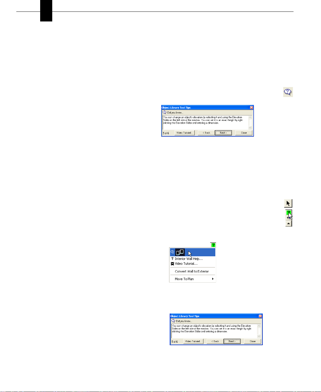
5 (optional) Pressing F1 while many tools are active will
access the help file for that Tool.
Video Tutorials
Video Tutorials are available for drawing tools and other
commonly-used features. These tutorials can be accessed
three ways.
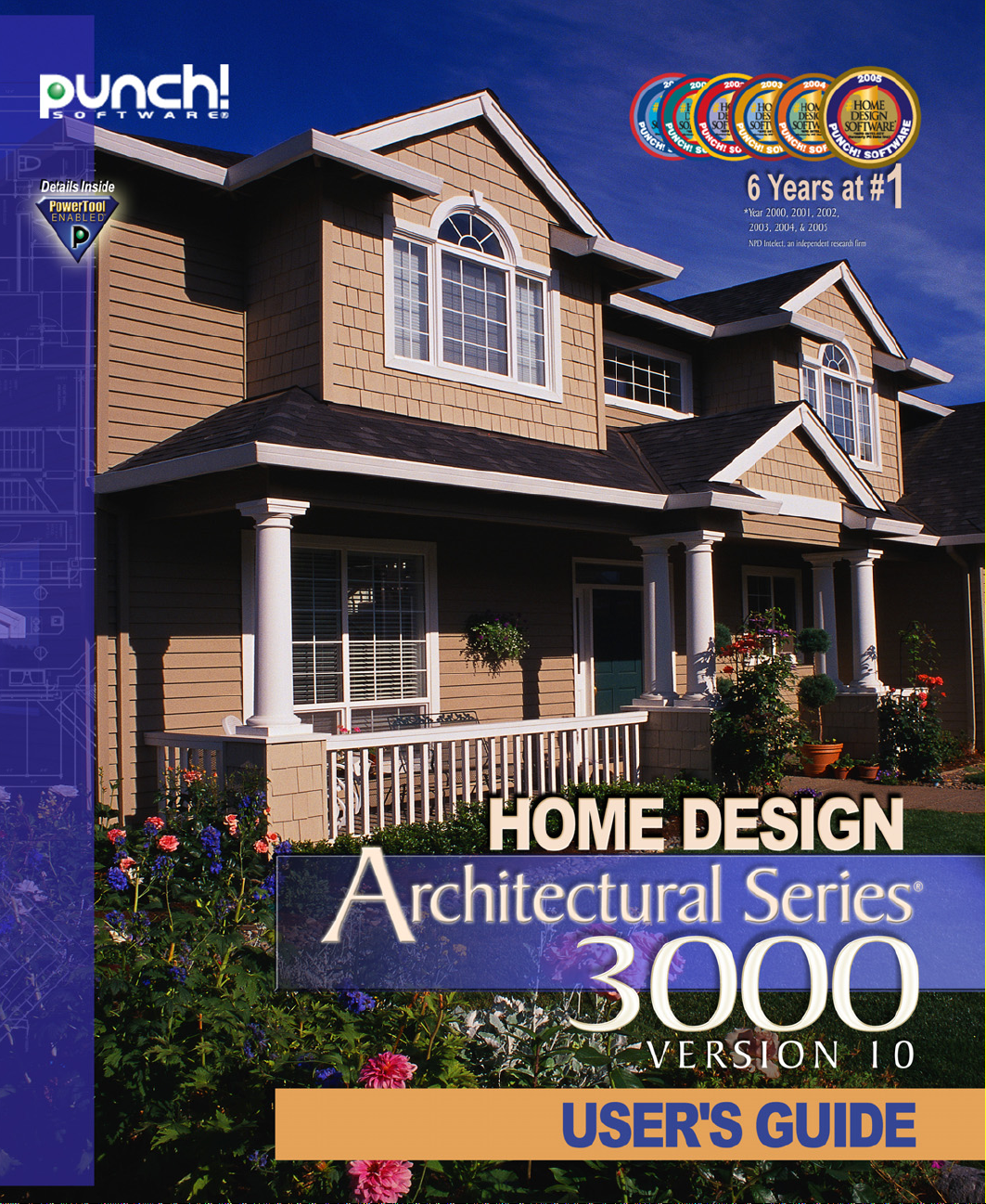
To access video tutorials from Tool Guides
1 On the Standard toolbar, click the Selection Tool.
2 Click the feature, object or plant that you want help
with, then click the Tool Guide tool. The Tips and
Tricks menu for that tool is displayed.
2 Navigate through the Help System until the topic you
need is displayed.
3 Click the Show Me button. A short video will be played
showing how the tool or feature works.
Technical Support
Before contacting Punch! Technical Support, please verify
that the answer to your question is not available from one of
the following resources:
■ Punch! Home Design Architectural Series 3000 User’s
Guide
■ Punch! AS3000 Help System
■ Video Tutorials
■ To automatically launch your browser and visit the
Punch! Software website, click the Connect to
Punch! button at the upper right of your window.
■ The Punch! Online Community is available at
http://forums.punchsoftware.com. At the Online
Community users can post questions and trade useful tips
and tricks.
■ The Customer Support Center is available at
http://punch.custhelp.com. At the Customer Support
Center you can register your software, search the
knowledge base or ask a question, if necessary.
The Customer Support Center can only answer questions that
are related to features of Punch! Home Design Architectural
Series 3000. They cannot answer specific questions about
home building, local building codes and so on.
3 Click the Video Tutorial button on the Tips and Tricks
following details:
menu. A short video will be played showing how the tool
When contacting the Support Center, please provide the
works.
■ Serial Number - located on the Help > About Punch!
Home Design dialog box
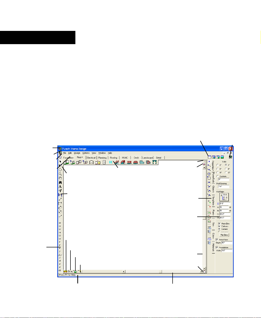
To access video tutorials with a right-click
1 On the Standard toolbar, click the Selection Tool.
2 Click the Context Help Button.
3 Right-click the feature, object or plant that you want
help with. The Quick Access menu for that tool,
object or plant is displayed.
4 Click Video Tutorial on the pop-up window. A short
video will be played showing how the tool works.
■ Your computer’s operating system
■ Make and model of your computer
■ Video card manufacturer and model
■ Video card driver date and version
■ Video RAM
■ Display settings, including hardware acceleration
After registering your program, you will receive 60 days of
free technical support
of your computer with the program running and have the
above information handy. The technical support contact
To access video tutorials from Help
1 On the Help menu, click Contents or press F1.
information can be located at the Customer Support Center http://punch.custhelp.com.
6 PUNCH! Home Design Architectural Series 3000 User’s Guide
. When you call, you should be in front
Page 12
Chapter 2
Window Layout
The Punch! AS3000 window provides an assortment of features that make it easy to create precise home plans. This
chapter describes the basic components.
In most cases, this chapter does not provide detailed information on standard Windows concepts or on specific menu items.
For information on standard Windows concepts, such as the mouse, the Control menu, the window border, the maximize
button, dialog box controls and so on, refer to Windows online Help.
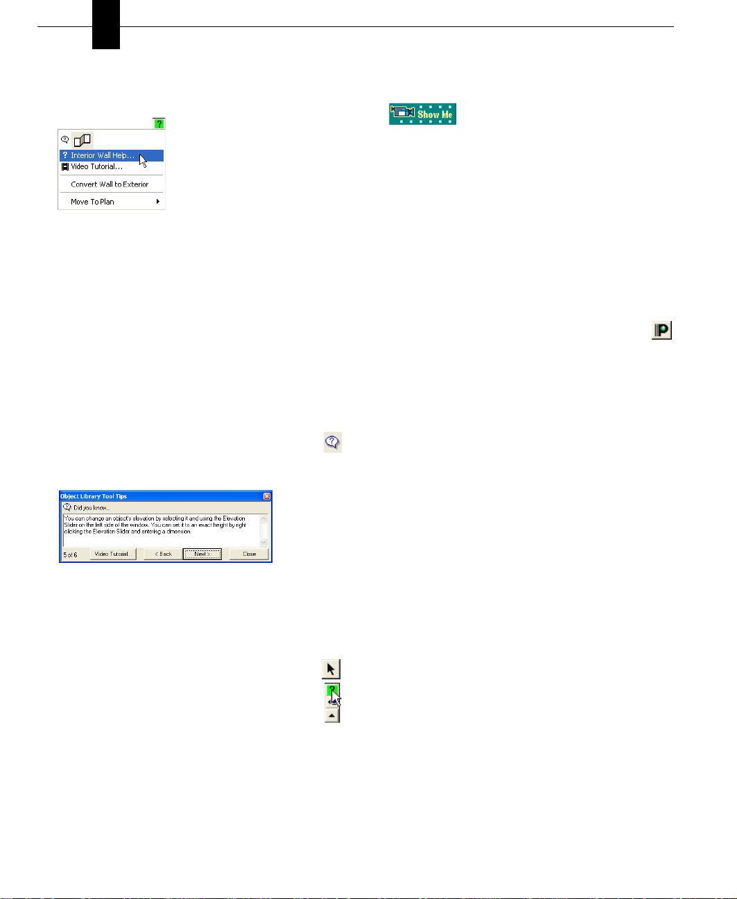
title bar
menu bar
tips & tricks
plan tab
elevation
slider
standard toolbar
annotation and
dimension bar
virtual
ruler
measurement
tools
working floor button
selection filter
plan toolbar
design window
LiveView
icons
context help button
snaps button
Preview Bar
property
bar
vertical
scroll bar
compass
Launch Punch!
websites
status bar
horizontal scroll bar
PUNCH! Home Design Architectural Series 3000 User’s Guide 7
Page 13
Chapter Window Layout
2
Title Bar
The title bar extends across the top of the application
window. It displays the name of the program and the name of
the current drawing file. Using the buttons at the right end of
the title bar you can minimize, maximize, close or restore the
window. You can also maximize or restore a window by
double-clicking on the title bar. Double-clicking the Control
menu box at the left end of the title bar is a quick way to exit.
If the application is running in a window, rather than
maximized, dragging the title bar moves the entire window
on the desktop.
Menu Bar
You can choose menu items using either the mouse or the
keyboard. To use the mouse, click the menu name; when the
menu drops down, click the item you want. Menu items with
an arrow to the right display cascading menus when you
place the pointer over one of them. When you highlight a
menu item, a description is displayed on the status bar.
To use the keyboard, press the ALT key and type the
underlined letter in the menu name, then type the underlined
letter in the menu item’s name. If there is a cascading menu,
you must type another letter. You can also use the arrow keys
to move through menu items and press ENTER to select one.
The ESC key backs out of the menu items one level at a time.
There are single-key or key combination shortcuts for certain
frequently-used menu items. Each menu lists available
shortcut keys to the right of the item’s name. You can use the
techniques for choosing menu items in combination.
Tips & Tricks
Punch! AS3000 makes it easy to get started by providing
users with tips and tricks for each Tool. Tips & Tricks
provide information about each tool and some general
information about the program. Tips & Tricks can be turned
off and on to suit your needs.
To access general tips & tricks
■ On the Standard toolbar, click the Tips & Tricks
Button.
To access tips & tricks for a specific tool
1 On any plan tab, click the tool you want to learn more
about.
2 Click the Tips & Tricks Button, the Tips and Tricks
menu for that tool is displayed.
To access tips & tricks for a part of your 2D drawing
1 On the Standard toolbar, click the Selection Tool.
2 Click the Context Help Button.
3 Click the feature, object or plant that you want help
with. The Quick Access menu for that feature, object
or plant is displayed on the right side of the window.
Plan Tabs and Toolbars
Clicking one of the plan tabs will activate the toolbar for that
plan layer. For example, if you select the Landscape tab, the
Landscape toolbar will appear. In addition, when you click
the small arrow next to the title of the tab, you have the
option of viewing or hiding other plans. This will be useful,
for example, if you want to see the foundation plan with
landscaping, but without exterior and interior walls.
To find out what a certain tool represents, hold the pointer
over the tool and read the description on the status bar at the
bottom of the window.
8 PUNCH! Home Design Architectural Series 3000 User’s Guide
4 Click the Tips & Tricks listing at the top of the pop-up
window. The Tips & Tricks Button menu for that feature,
object or plant is displayed.
5 (optional) Click Back or Next to cycle through the tips
available for that feature, object or plant.
Page 14
Elevation Slider
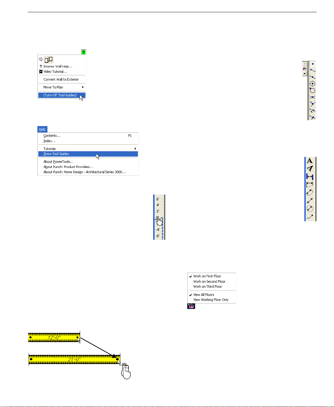
To turn tool guides on and off
■ To turn off Tool Guides, click (Turn-Off Tool Guides).
■ To turn on Tool Guides, on the Help Menu click Show
Tool Guides.
Elevation Slider
With Punch! AS3000’s Elevation Slider you can
easily move selected items vertically off “ground
level”. This feature makes it a snap to make sure
windows, doors, plants and so on are in exactly the
position you want. Simply select the object or feature
to be raised and move slider by clicking and dragging
with the mouse. For a more information, see
Elevation Slider” on page 176.
“Using
Virtual Ruler
The Virtual Ruler works like a real-world tape measure. It
stores away in the corner of the window until you need it.
Then with one click it is displayed in the middle of the
window, where you can move it into any position necessary
to make a needed measurement. It then stores away until you
need it again. To move the Virtual Ruler, click and drag from
the center. To resize, click and drag on one of th e large blac k
dots at either end.
You are not constrained to vertical or horizontal, the Vertical
Ruler can be stretched in any direction necessary.
Snaps Bar
On the Snaps bar you will find tools that you will
begin to find indispensable. Each tool has a very
specific function and will allow you to place walls,
doors, windows and many other things exactly where
you want them - the first time!
see “Snaps and Annotations”, which begins on page
23.
From placing a window exactly 6'4" from a corner to
placing a table lamp exactly in the center of the end
table, you will begin to use Snaps in concert with
almost every other drawing tool in Punch! AS3000.
For more information,
Annotation Bar
On the Annotation bar there are two tools for text,
straight and angled, and several tools to let you
dimension part of your design where automatic
dimensioning may not be available.
With these tools, you will be able to measure and label
any part of your drawing. If you want, you can store
these labels on the Detail Tab so you have the option of
turning them off when you want to see your design in a
more unobstructed state.
“Snaps and Annotations”, which begins on page 23.
For more information, see
Measurement Tools
The measurement tools include associative dimensions,
window/door callouts and the shortcuts to calculate floor
square footage.
Associative Dimensioning are the measurements that appear
as you are adding features. For example, the Associative
Dimensioning feature will show how far from the ends of
each wall the window is positioned.
Drag
When the Window/Door Callouts option is checked, the
measurements of all window and door openings will be
shown with the wall measurements and be displayed in the
floorplan view.
PUNCH! Home Design Architectural Series 3000 User’s Guide 9
Page 15
Chapter Window Layout
2
Selecting one of the three square footage options will cause
Punch! AS3000 to make that calculation and display it in the
Status Bar.
Working Floor Button
Use the Working Floor button to switch the current view
based on the number of floors in your home plan. When
you click the Working Floor button, a pop-up menu is
displayed. Simply click the floor on which you would like to
work to switch the current working floor.
Status Bar
The status bar is located in the lower left of the window and
displays prompts, program messages and measurements. It is
a good place to look when you are holding the pointer over
certain buttons or menu items to find their function.
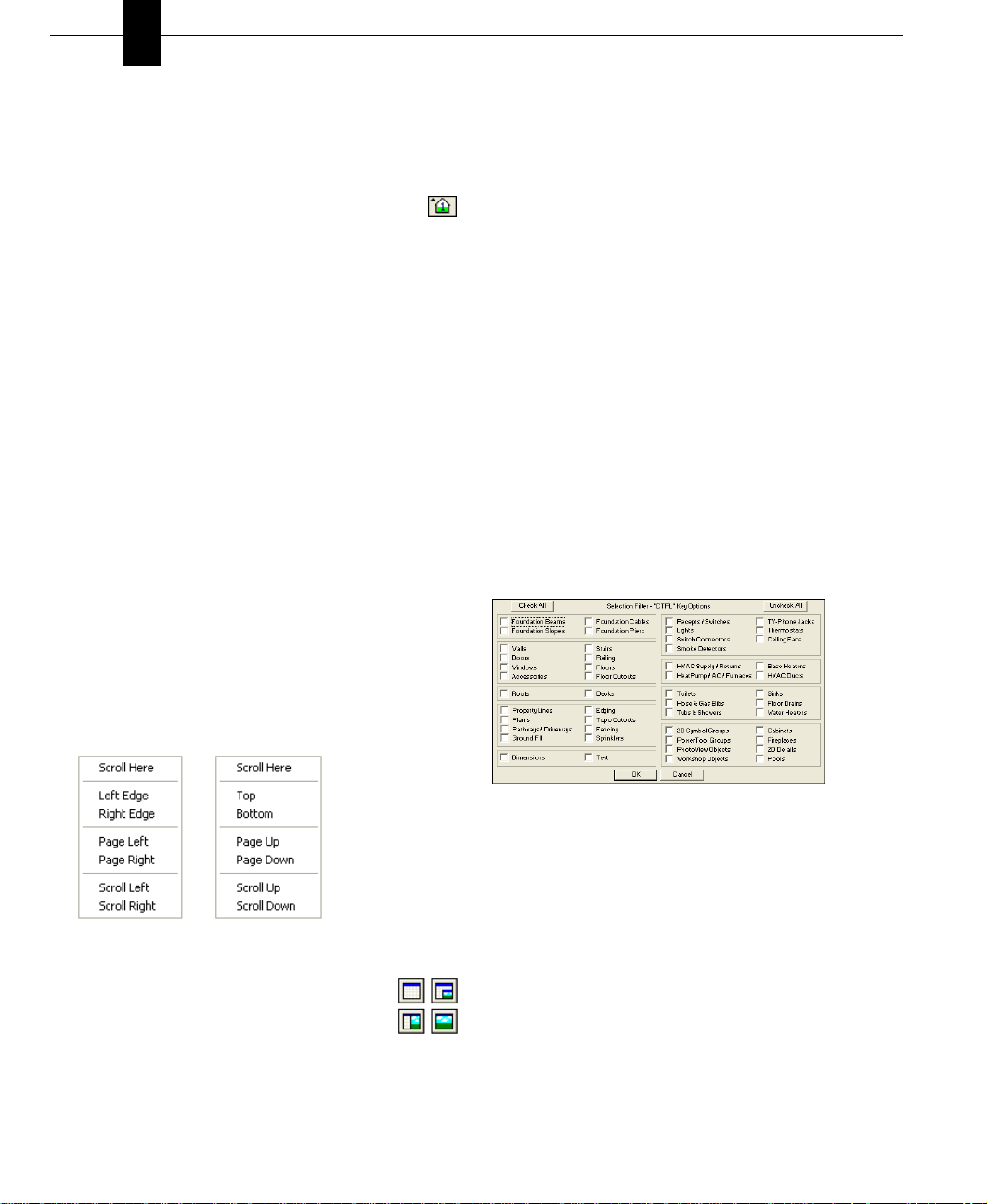
Scroll Bars
Scroll bars provide a way for you to pan across the drawing,
that is, to change the part of the drawing visible in the
window, without changing the level of magnification.
■ To pan the drawing in small increments, click the scroll
arrow that points in the direction you want to pan.
■ To pan in larger increments, click the control shaft,
between the scroll box and a scroll arrow.
■ To pan by a custom increment, drag the scroll box in the
direction you want to pan.
■ To position at a specific area of the page, right-click the
scroll bar and click the wanted area on the pop-up menu
that is displayed.
When you want to focus primarily on your 2D actions while
maintaining a clear view of the 3D design, select Split Plan/
3D View. Then, when you’re ready to add materials and
colors to your Dream Home it will be easier in the 3D Full
View mode.
Properties Bar
You can easily modify features you have previously drawn
by selecting them and editing their properties on the
Properties Bar. You can even set the Properties Bar to
automatically display when a feature is selected by clicking
Auto Activate.
Selection Filter
There will be times that you will place items atop one
another. To make it easier to select each layer use the
Selection Filter. Click the type of feature(s) you want to be
able to select. When you hold down the CTRL key, you will
only be able to select those features.
For example, to select a transom window placed over a door
check “Windows” on the Selection Filter. Hold down the
CTRL key and click where the window and door are placed
and you will only select the window.
Preview Bars
You can click and drag objects, templates, materials, colors
and so on from their Preview Bars onto your plan. The
Preview Bar changes to reflect your selection. For instance, if
you click the Plant Bar, plant options will be displayed.
LiveView Icons
It is in the LiveView window where you see your
designs come to life! The default view is Plan Full
View. When you load Punch! AS3000, this is the
view you will see. With the 3D Quarter View option, use
most of your window for drawing, yet be able to view your
design in 3D. For a full explanation see
“Working with LiveView”, which begins on page 177.
10 PUNCH! Home Design Architectural Series 3000 User’s Guide
the chapter titled
Clicking one of the buttons on the PowerTool bar launches
one of the associated Punch! AS3000 applications. For
example:
■ Launch Topo Designer. To learn more about Topo
Designer, see the chapter titled “Topo Designer”, which
begins on page 47.
■ Launch Material Workshop. To learn more about
Material Workshop, see the chapter titled “Material
Workshop”, which begins on page 203.
Page 16
■ Launch Roofing Wizard. To learn more about Roofing
Wizard, see the chapter titled “Roofing Wizard”, which
begins on page 121.
All PowerTools launch in this same fashion, whether they
were written by Punch! Software, LLC or by a third-party
developer.
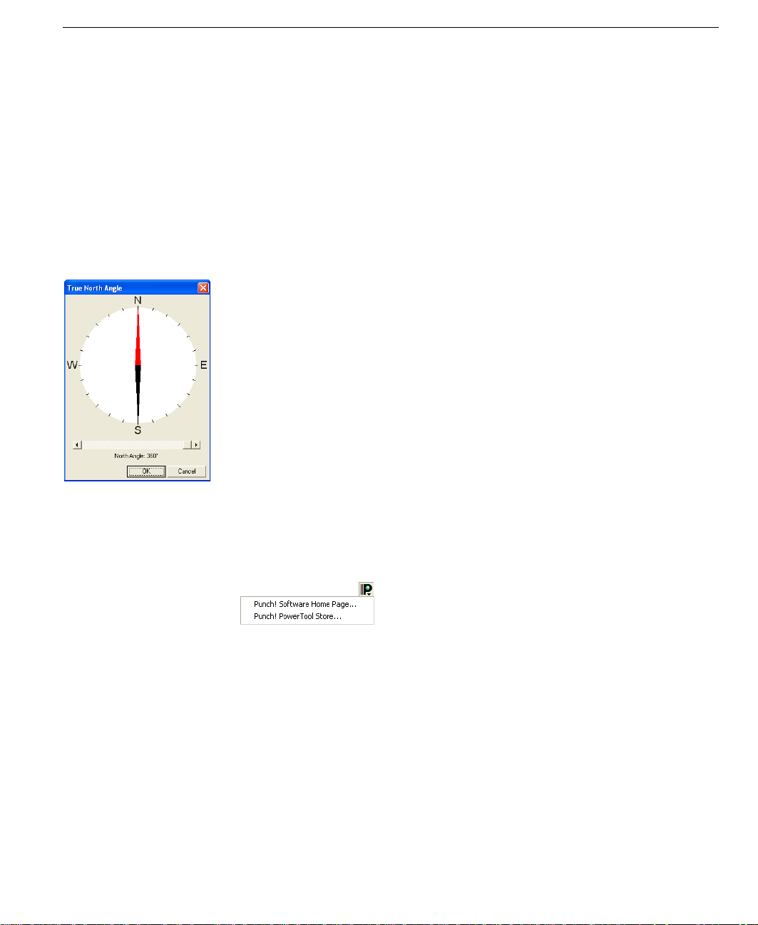
Compass Setting
With the True North compass you can make sure that your
design is placed correctly on your lot. The compass is also
useful to accurately depict the direction of shadows and the
sun’s position.
Compass Setting
PunchSoftware.com
With the click of one button, you can visit the Punch! website
at www.punchsoftware.com or the Punch! PowerTool Store
at www.punchsoftware.com/PowerTool_store.htm
■ To automatically launch your
browser and visit the Punch!
home page, click the Punch!
Software Websites button at the upper right of your
window, then click Punch! Software Home Page.
■ To automatically launch your browser and visit the
Punch! PowerTool Store, click the Punch! Software
Websites button at the upper right of your window, then
click Punch! PowerTool Store.
PUNCH! Home Design Architectural Series 3000 User’s Guide 11
Page 17

Chapter Window Layout
2
12 PUNCH! Home Design Architectural Series 3000 User’s Guide
Page 18

Chapter 3
A Quick Tour
To get the most benefit from Punch! Home Design Architectural Series 3000, you should take a minute to become familiar
with some of its basic concepts. This chapter describes a few settings you should know, as well as some of the terms used
throughout this guide.
Punch! Home Design Architectural Series 3000 is not just one software application, but several applications that can be
used together. Once you’ve mastered Punch! AS3000, additional tools are available to customize your home plans:
Estimator, Material Workshop, PhotoView, RealModel and 3D Custom Workshop. Information on the use of all these
tools can be found in this User’s Manual.
With Punch! AS3000 you can set a precise drawing scale, define units of measurement and set the reference grid. There are
also many performance settings you can apply to optimize drawing speed and 3D viewing.
PUNCH! Home Design Architectural Series 3000 User’s Guide 13
Page 19
Chapter A Quick Tour
3
About This Guide
The text and graphics in this guide are tailored to help you
find the information you need quickly and get the most out of
Punch! AS3000. Each section of this guide is divided into a
series of step-by-step instructions, making it easy for you to
scan a page to find exactly what you need. You can also refer
to the index for additional topics on the same subject, if
necessary.
Instructions for installing and using Microsoft Windows do
not appear in this guide. If you’re uncomfortable with your
knowledge of Windows or with the concepts associated with
a user interface object, you should review Windows online
Help before attempting any serious work with Punch!
AS3000.
Basic Terms
The following is a list of terms used throughout this guide.
Take a moment to familiarize yourself with the language
used in this guide and to reinforce your understanding of
basic terminology.
Click
Pressing and releasing the left mouse button once.
Right-click
Pressing and releasing the right mouse button once.
Double-click
Pressing and releasing the left mouse button twice.
Click and drag
Pressing the left mouse button, holding it down and moving
the mouse simultaneously.
Drag-and-drop
Clicking to select an item, holding down the mouse button,
then dragging and releasing.
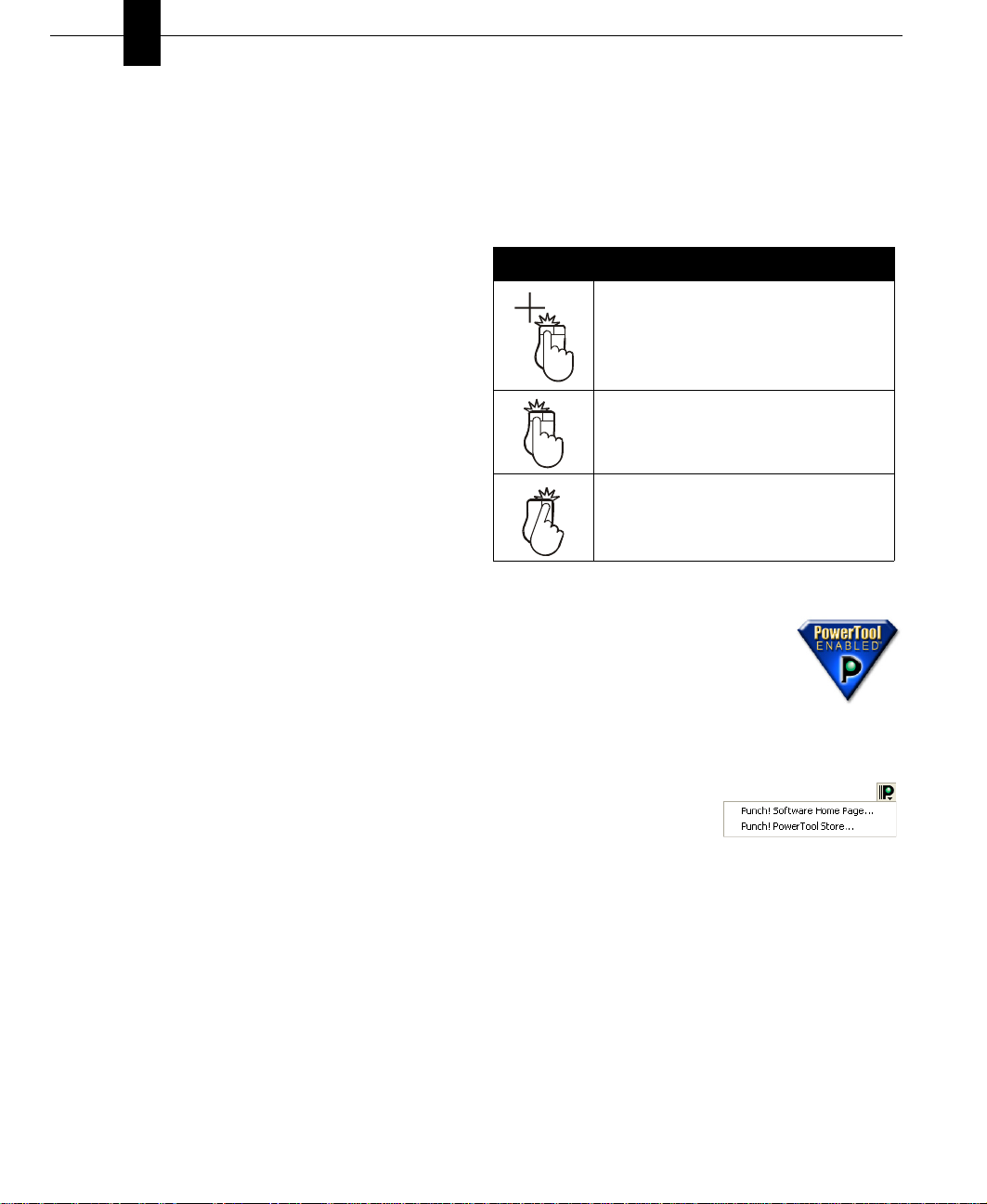
Graphic Cues
This guide uses several types of graphic elements. Some
show the window or a dialog box that will appear during an
operation. When this type of graphic illustration is used,
every effort is made to show the element exactly as it is
displayed on the window.
Graphic Cues Used in this Guide
Convention Meaning
mouse click that selects a point—the
number, when present, specifies the mouse
click’s position in a series of clicks
2
click and drag operation—beginning of
arrow indicates where to start; end of arrow
Drag
indicates where to stop
a right mouse click —the number, when
present, specifies the mouse click’s position
in a series of clicks
2
Punch! PowerTools™
Punch! Home Design Architectural Series
3000 is PowerTool enabled. Punch!
PowerTools seamlessly add additional
features and functionality to your program to
make it easier to create your dream home!
Whenever more PowerTools become available, they are
offered to users at the Punch! PowerTool Store.
■ To automatically launch your
browser and visit the Punch!
PowerTool Store, click the
Punch! Software Websites button at the upper right of
your screen, then click Punch! PowerTool Store.
Scroll
Using the scroll bars on the sides of the application window
by clicking the slider box, holding down the mouse button
and dragging.
14 PUNCH! Home Design Architectural Series 3000 User’s Guide
Defining Your Lot Size and Topography
With Punch! AS3000 you define lot size and all
topographical information in the Site Planner and
Topography Designer PowerTools.
For more information, see “Topo Designer”, which begins on
page 47.
Page 20
Setting the Scale
Setting the Scale
Scale is the ratio between real-world size of objects and items
in your drawing and their size when printed.
The default drawing scale is 1/4" = 1', meaning that 1/4" on
your drawing plan equals one foot in real-world size. You
can customize scale settings at any time to suit your needs, as
well as print your drawing to scale.
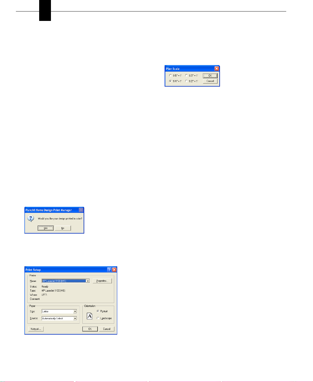
To set the drawing scale
1 On the Design menu, click Plan Scale. The Plan Scale
dialog box is displayed.
2 Click a new scale setting, then click OK. The new scale is
applied to your plan drawing.
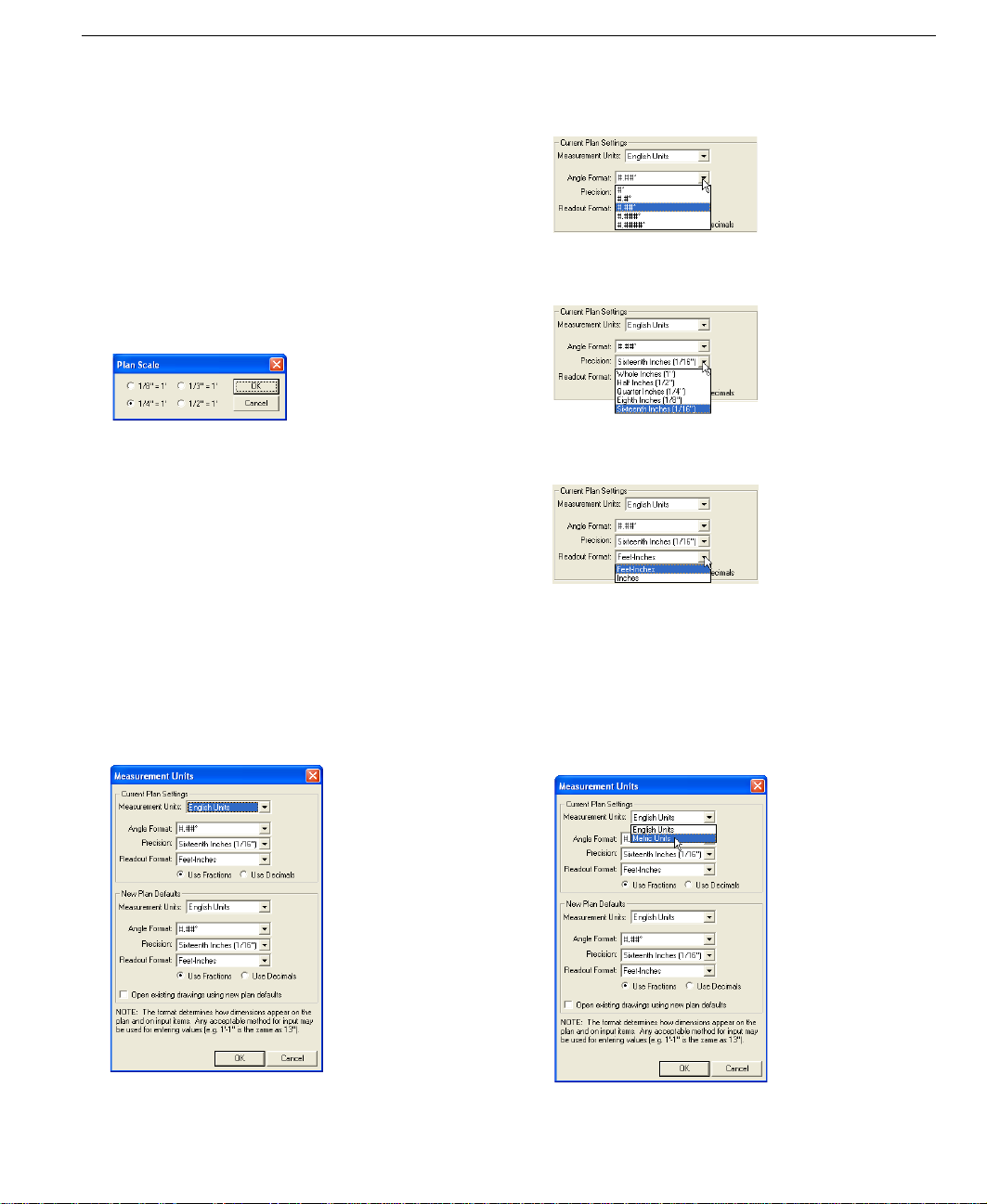
Setting Unit of Measurement
You can set units of measurement in Punch! AS3000 by
selecting either English measurements or Metric
measurements. You can also set the default measurements
and options to be applied when any previously-drawn design
is opened.
3 (optional) Click the arrow next to Angle Format and
select the number of decimal points you want to use.
4 (optional) Click the arrow next to Precision and select the
number of decimal points you want to use.
5 (optional) Click the arrow next to Readout Format and
select the format you want.
6 Click OK. The unit of measurement and options you
selected are applied.
To use English measurements
1 On the Design menu, click Unit of Measure. The
Measurement Units dialog box is displayed.
2 Click English Units.
PUNCH! Home Design Architectural Series 3000 User’s Guide 15
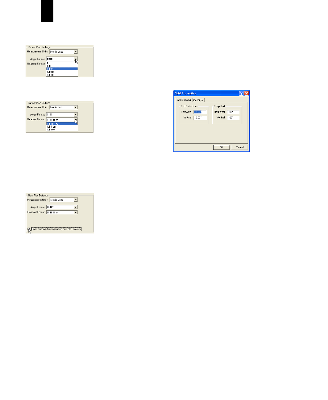
To use Metric measurements
1 On the Design menu, click Unit of Measure. The
Measurement Units dialog box is displayed.
2 Click Metric Units.
Page 21
Chapter A Quick Tour
3
3 (optional) Click the arrow next to Angle Format and
select the number of decimal points you want to use.
4 (optional) Click the arrow next to Readout Format and
select the format you want.
5 Click OK. The unit of measurement and options you
selected are applied.
To set defaults for previous designs
1 Follow the instructions for either English or Metric units
outlined above, then click the box to set the defaults for
all previously-drawn designs.
2 Click OK. The defaults will be applied to any previously-
drawn designs when it is opened.
Using the Grid
With Punch! AS3000 you can set specific grid properties that
aid in drawing your home plan. You can set points based on
the reference grid which is useful when you want to make
sure certain points are specified precisely.
Grid settings have a direct impact on the ease of aligning
objects, snapping objects to the grid and so on. When using
the Snap to Grid feature, items that are dragged and dropped
on the design window are automatically snapped, or placed,
to align with the current grid. By default, Snap to Grid is
turned on.
Grid properties can also be set by accessing the right-click
menu with nothing selected.
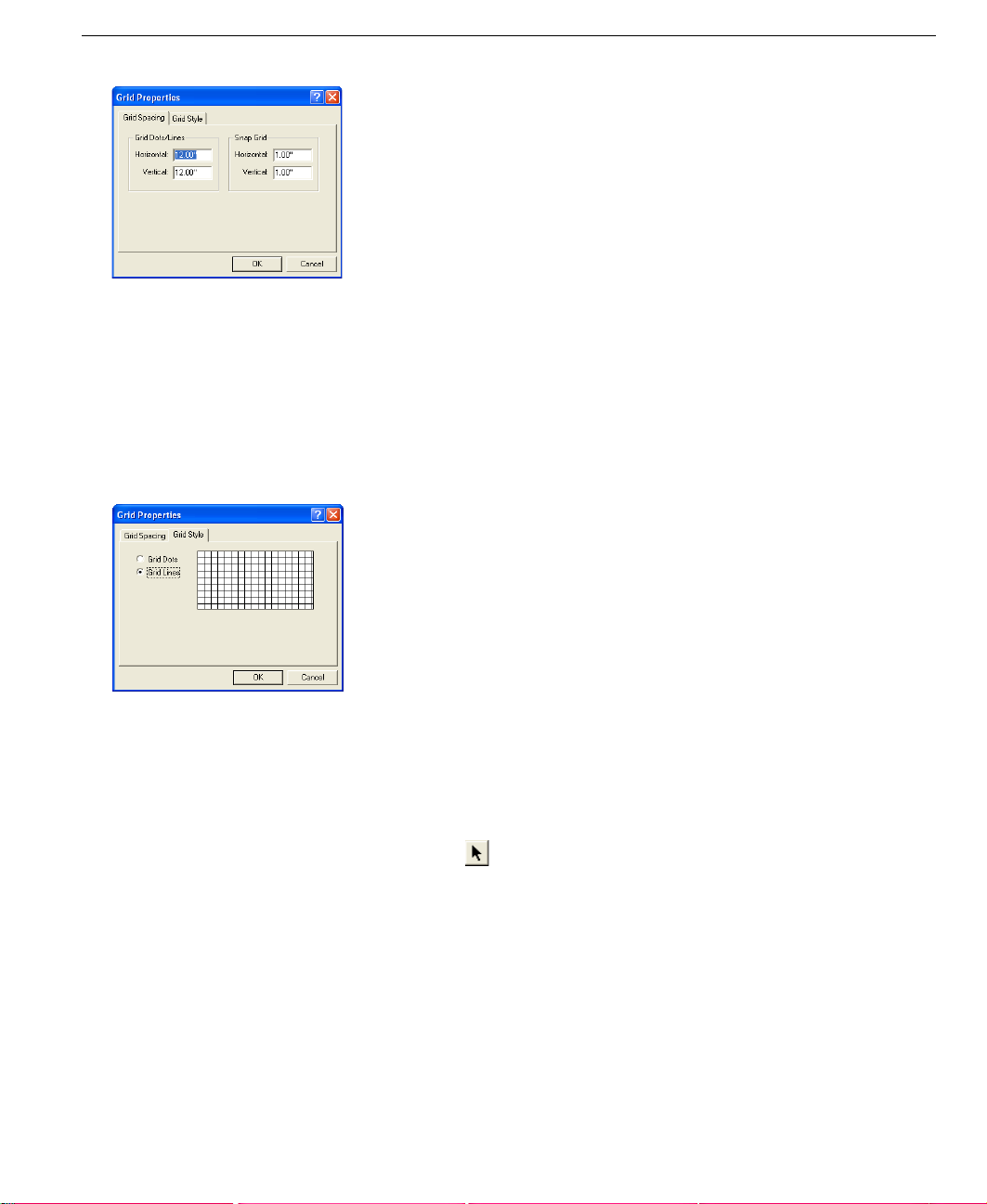
To define Snap to Grid settings
1 On the Options menu, click Grid Properties or right-click
on your design window and click Grid Properties on the
pop-up menu that is displayed. The Grid Properties
dialog box is displayed.
2 On the Grid Spacing dialog box, type new measurements
into the Snap Grid section, then click OK. Items you
draw or drag-and-drop into the design window will now
snap to the measurements you defined.
Note: Initially, the grid is set at 12 i nches, m aking it easy to
visualize each plan square as exactly one square foot, but can
be customized to meet your particular design needs.
Note: Snap settings can be set as low as 0.10 inch (English),
0.002 m (Metric), and still show visible movement along the
grid. Snap settings can be set as high as 500 inches (English),
12.70 m (Metric).
To select grid spacing
1 On the Options menu, click Grid Properties or right-click
on your design window and click Grid Properties on the
pop-up menu that is displayed. The Grid Properties
dialog box is displayed.
2 Type new horizontal and vertical measurements in the
Grid Dots/Lines section of the Grid Spacing page, then
click OK. The new grid spacing measurements are
applied.
You can customize grid settings by selecting grid spacing,
grid style and whether the grid is hidden from view or
displayed.
16 PUNCH! Home Design Architectural Series 3000 User’s Guide
Page 22
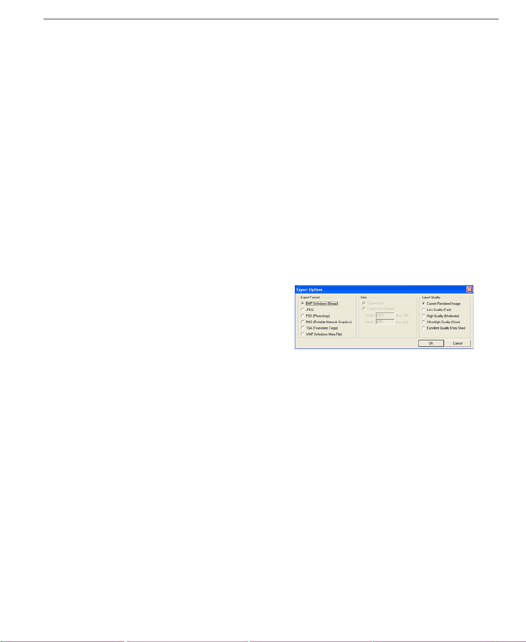
To change the grid style
1 On the Options menu, click Grid Properties or right-click
on your design window and click Grid Properties on the
pop-up menu that is displayed. The Grid Properties
dialog box is displayed.
2 Click the Grid Style page tab.
3 Click either Grid Dots or Grid Lines, then click OK. The
new grid style is applied.
Using the Grid
is disabled. To enable Snap to Grid, simply recheck the
menu item.
To display the grid
■ On the Options menu, click to check Grid Visible or
right-click on your design window and click Grid Visible
on the pop-up menu that is displayed. The grid is
displayed on the design window.
Note: Grid Dots/Lines can be set to as low as 1 inch
(English), 0.02 m (Metric), and still be viewable. Grid Dots/
Lines can be set as high as 500 inches (English), 12.70 m
(Metric).
To move objects/features along the grid
1 On the Standard toolbar, click the Selection Tool.
2 Click the object or feature you want to move.
3 Using the arrow keys on your keyboard, move the object
or feature into position.
Note: Each time you press an arrow key, the object or
feature will move one increment that you have set in
“To
define Snap to Grid settings” on page 16.
To turn off Snap to Grid
■ On the Options menu, click to uncheck Snap to Grid,
press CTRL+R, or right-click on your design window
and click Snap to Grid on the pop-up menu. The feature
PUNCH! Home Design Architectural Series 3000 User’s Guide 17
Page 23

Chapter A Quick Tour
3
18 PUNCH! Home Design Architectural Series 3000 User’s Guide
Page 24

Chapter 4
File Management
When you start Punch! AS3000, a new blank drawing file is displayed. If you are returning to work on an existing drawing,
you must open it, or display it on the screen. Opening a file involves clicking Open on the File menu and specifying the
name of the file you want to open. Once you have opened a file, you can edit, import, export, print, view and save it.
You can have more than one file open at a time. The exact number of files you can have open depends on the amount of
memory in your system and the complexity of the home plan file. When you open a file, Punch! AS3000 displays it in a
new window.
The changes you make to a plan drawing occur only in your computer’s memory until you save them. To preserve a
drawing for later use, you must save it to a file. If you want to save a drawing using its current name or if you want to save
a new, untitled drawing, use Save. If you want to save a drawing using a new name, use Save As.
At any point during the design process you can import objects created in 3D Custom Workshop to further customize your
design. In addition, you can export a 3D LiveView rendering to make it easy to share your design with friends.
PUNCH! Home Design Architectural Series 3000 User’s Guide 19
Page 25

Chapter File Management
4
Opening a File
Opening a file copies the data it contains into memory,
making it available for you to edit or print the plan drawing.
To open an existing file
1 On the File menu, click Open. The Open dialog box is
displayed.
2 In the File Name box, type the name of the file you want
to open, or search for the file by switching folders or
drives.
3 When you see the name of the file you want to open,
click to select it.
4 Click OK.
To see a list of recently opened files
1 On the File menu, highlight Open Recent. The Open
Recent listing is displayed.
2 On the Open Recent pop-up, click the file you want to
open. The file loads into memory.
To clear the recently opened files listing
1 On the File menu, highlight Open Recent. The Open
Recent listing is displayed.
2 On the Open Recent pop-up, click Clear Recent Designs
List. A warning box is displayed.
3 Click Yes to delete all files from the listing. Click No to
leave the listing unchanged.
Saving a File
When you open a file, Punch! AS3000 copies the file to your
computer’s memory. As you work, you modify the copy
stored in memory. Any system failure or loss of power
destroys that copy. To save your work permanently, you must
save it to a file on a disk. A good rule of thumb is to save
every 15 minutes or after you’ve completed any work you
wouldn’t want to redo.
When you click the Save command, Punch! AS3000 saves
the active drawing using the name and location you last gave
it. You can create more than one version of a drawing or save
copies on another disk for safekeeping. You can save each
version under a different name, or you can save them under
the same name in different folders or on different disks.
To save an existing file
■ On the File menu, click Save or right-click, then click
Save on the pop-up menu that is displayed or press
Ctrl+S.
To save a new, unnamed file
1 On the File menu, click Save As. The Save As dialog box
is displayed.
2 Type a file name in the File Name text box. Punch!
AS3000 automatically adds the PRO extension, unless
you specify another extension.
3 Click OK.
To save a file to a different name, drive, or folder
1 On the File menu, click Save As. The Save As dialog box
is displayed.
2 If you want to save the drawing under another name, type
a name in the File Name text box.
3 If you want to save the drawing to a different drive or
folder, click a different drive and folder, or type the
complete path in the File Name text box.
4 Click OK.
Closing a File
When you finish working with a file, close it to remove the
window from the screen and to free up your computer’s
memory. When you are done working in Punch! AS3000,
close all your files and exit the program.
To close a file
■ On the File menu, click Close. If you have unsaved
changes in your plan drawing, Punch! AS3000 prompts
you to save them before it closes the file.
To close all open files and exit Punch! AS3000
■ On the File menu, click Exit. If any open drawings have
unsaved changes, Punch! AS3000 prompts you to save
them before it closes their files.
Accessing the Pre-Drawn Homeplans
Punch! AS3000 includes a wide variety of homeplans for you
to alter. The included homeplans are located in the directory
where you installed the program, in a subdirectory called
“Plans”.
20 PUNCH! Home Design Architectural Series 3000 User’s Guide
Page 26
Importing Files
To open a pre-drawn homeplan
1 Open the Punch software and click File>Open.
2 On the screen that appears, click the down arrow beside
My Documents and select C Drive.
3 From the folders that appear in the window, double-click
Program Files.
4 From the next set of folders that appear, click Punch!
5 Select Plans from the next set of folders.
6 The 20 plans will appear in the window. Double-click the
plan you wish to view.
Note: All plans included with Punch! AS3000 are the
copyright of Wolfgang Trost Architects. The plans and 3D
computer images are for conceptual purposes only. You must
have any plans provided in, or generated by, Punch! Home
Design Architectural Series 3000 checked by a licensed
architect before you build. Punch Software LLC and
Wolfgang Trost Architects are not liable for errors, omissions
or any other deficiencies in these conceptual plans. Complete
sets of building plans for these homes are available by
contacting Wolfgang Trost Architects at
www.wolfgangtrost.com
Importing Files
Punch! Home Design Architectural Series 3000 is 30
programs in one. All of these programs integrate seamlessly;
objects created with Punch! 3D Custom Workshop and
cabinets designed in Punch! Cabinet Wizard are available for
import into your floor plan.
To import a 3D Custom Workshop object
1 On the File menu, click Import>Punch! 3D Custom
Workshop Object. The Import Punch! 3D Object dialog
box is displayed.
2 In the File Name box, type the name of the file you want
to open, or search for the file by switching folders or
drives.
3 When you see the name of the file you want to open,
click to select it.
4 Click OK. The object is placed in the center of your 2D
design.
Note: Double-click the object to re-open it in 3D Custom
Workshop.
Exporting Files
You can export a rendering of your LiveView window to
BMP, JPG, PDS, PNG, TGA and WMF format. Files can be
exported in Textured, Wire-Frame and ClearView modes.
The exported file will appear just as your LiveView window
does. Be sure to render your drawing in high-resolution
before exporting. Size is also controlled by how your
LiveView window appears, the larger the LiveView window,
the larger the file will be. For more information on
controlling the LiveView environment,
LiveView”, which begins on page 177.
By exporting your design to VRML, it becomes available for
viewing with a VRML viewer or through a web browser
(provided an appropriate plug-in is installed). These helper
applications and plug-ins are available as free downloads on
the Internet.
To export
1 On the File menu, click Export 3D>LiveView Image.
The Export Options dialog box is displayed.
2 Click the radio button next to the format you want to use,
then click OK. The Save As dialog box is displayed.
3 (optional) Click the radio button next to the Export
Quality that is needed, then click OK.
4 (optional) Set a size for the exported image, then click
OK.
5 Type a file name in the File Name text box. Punch!
AS3000 automatically adds the extension.
6 If you want to save the drawing to a different drive or
folder, click a different drive and folder, or type the
complete path in the File Name text box.
7 Click OK.
To export to VRML
1 On the File menu, click Export 3D>VRML.
2 In the File Name text box, type a name. Punch! AS3000
automatically adds the extension, then click OK.
see “Working with
PUNCH! Home Design Architectural Series 3000 User’s Guide 21
Page 27
Chapter File Management
4
Sharing Files Using the Content Folder
Punch! Home Design Architectural Series 3000 will look for
anything missing from a drawing in the Contents Folder.
Missing components could be custom textures, custom
plants, the topography grid files, PhotoView images, and so
on.
To share a design that has customized components, those
components need to be collected and placed in the Content
Folder, then the Content Folder will be emailed with your
home design plan.
Printing Floorplans
Punch! AS3000 prints using the current Windows printer
drivers. You can, however, print using any installed printer.
Using the Print dialog box you can specify a printer or plotter
from those currently installed. Your can print your drawing
in color or in black and white; it can be printed to scale or
you can print it all on one page, whatever you require. Follow
these steps to print your 2D drawing.
To print to fit page
1 On the File menu, click Print to Fit Page or press Ctrl+P.
A Print Manager menu will ask if you want to print your
drawing in color. Click Yes to print in color; click no to
print in greyscale.
5 Click OK.
To print to scale
1 On the Design menu, click Plan Scale. The Plan Scale
dialog box is displayed.
2 Click the radio button next to the scale you want to use.
Click OK.
Note: Gridlines will print if they are visible when the
drawing is printed.
3 On the File menu, click Print to Scale. A Print Manager
menu will ask if you want to print your drawing in color.
Click Yes to print in color; click no to print in greyscale.
4 The Print dialog box is displayed.
5 Click the printer you want to use.
6 (optional) Change the paper orientation and size.
7 Click OK.
Printing a 3D LiveView Rendering
Punch! AS3000 streamlines the process used to print the 3D
LiveView images. With just a couple of clicks, you can print
beautiful, full-color renderings of your design.
To print a 3D LiveView rendering
1 On the File menu, click Print 3D LiveView, then select
Note: Gridlines will print if they are visible when the
drawing is printed.
2 The Print dialog box is displayed.
3 Click the printer you want to use.
4 (optional) Change the paper orientation and size.
22 PUNCH! Home Design Architectural Series 3000 User’s Guide
the quality needed. The print dialog box is displayed.
2 Click the printer you want to use.
3 (optional) Change the paper orientation and size.
4 Click OK.
Page 28

Chapter 5
Snaps and Annotations
Punch! Home Design Architectural Series 3000’s powerful Snaps Toolbar has many tools that make precision placement
easier. On the Snaps Toolbar there are a wide variety of precision drawing aids that will help in exact placement of walls,
doors, windows and so on.
Often, drawing a plan to scale is not enough to convey precise measurements. In such cases, you must notate the
measurements using manual dimension notes. Punch! AS3000, by default, automatically displays dimensions as you draw.
This makes it easy to create accurate drawings from the start.
In addition to the Virtual Ruler you can use a variety of dimension tools available in Punch! AS3000 to measure items that
are not automatically dimensioned. You can also obtain total square footage measurements for each floor of your home
design with the Square Footage menu item.
With the text tools you can add either straight or angled text to any area of your drawing. This feature is useful if you’d like
to name your home plan or add your address to the final drawing, for instance. You can select from any font installed on
your computer, as well as select style and size.
This chapter describes the dimension and measurement tools in Punch! AS3000 and how to add text to your drawing.
PUNCH! Home Design Architectural Series 3000 User’s Guide 23
Page 29
Chapter Snaps and Annotations
5
Snap to Endpoint
Punch! AS3000 gives you the power of snaps. With snaps,
you can define exactly what distance interior walls are placed
from other walls or begin exactly at the end of the wall when
drawing a roof section. You can move through the Snaps
Toolbar with the Tab key. Each time you press Tab, the next
Snap Tool is activated, Shift-Tab reverses the process.
The following examples show a few ways that Snaps will
help you during the design process; each Snap Tool works in
concert with many other tools in Punch! AS3000.
Accessing the Snaps toolbar
■ Click the Snaps On Tool. The Snaps
toolbar is displayed.
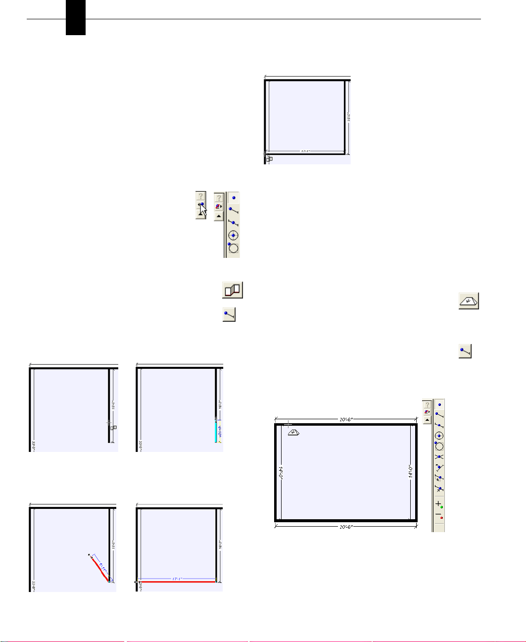
To snap a wall from the end of another wall
1 On the Floor Plan tab, click the Interior Wall
Tool.
2 On the Snaps toolbar, click the Snap to Endpoint
Tool or press TAB.
3 Click a wall on the design window. The wall will “snap
to” the endpoint nearest where you clicked.
5 Release the mouse button when the wall length you want
is reached.
Note: Each Snap Tool defaults back to “No Snap” after it is
used; double-click the Snap Tool to lock it in active mode. If
you have locked a Snap Tool and use the Tab key to activate
another tool, it will also be locked as active. To unlock it,
click “No Snap”.
Note: Walls are drawn from a centerline. When moving or
otherwise manipulating them, you are always working from
the centerline and snapping to them will do the same.
To snap a roof
1 On the Roofing Plan tab, click one of the Roof
Tools. The Preview Bar displays the pitches that
are available.
2 Click the roof pitch to select it.
3 On the Snaps toolbar, click the Snap to Endpoint
Tool or press TAB.
4 Click a wall on the design window. The roof will “snap
to” the endpoint nearest where you clicked.
4 Hold down the mouse button and drag. Notice that the
wall follows the pointer and automatically displays the
wall length.
5 Hold down the mouse button and drag until the cursor
touches another wall.
24 PUNCH! Home Design Architectural Series 3000 User’s Guide
Page 30
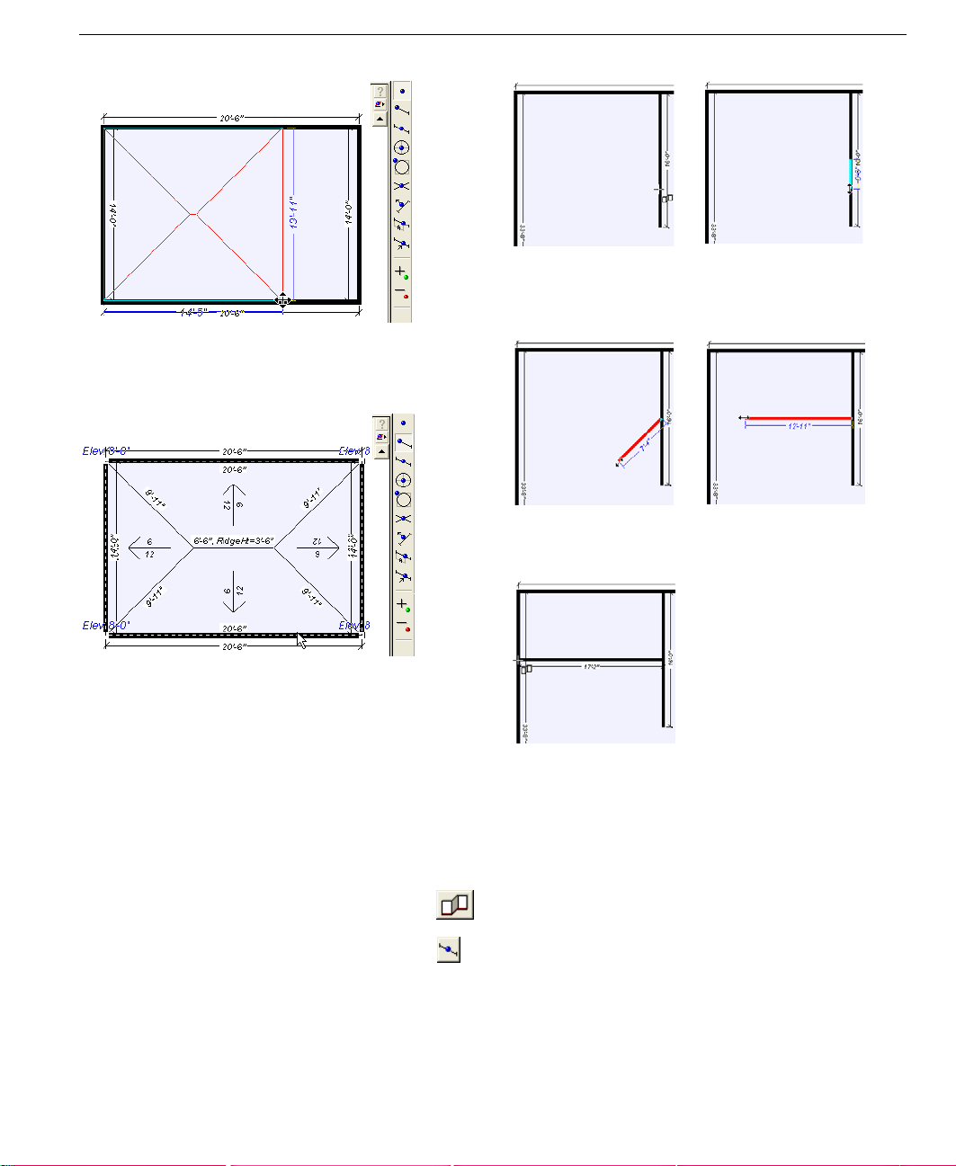
6 Press Tab to re-activate the Snap to Endpoint Tool. The
roof will automatically extend to cover the entire
perimeter.
Snap to Segment Centerpoint
4 Hold down the mouse button and drag. Notice that the
wall follows the pointer and automatically displays the
wall length.
5 Release the mouse button when the wall length you want
is reached.
7 Release the mouse button.
Snap to Segment Centerpoint
Snap to Segment Centerpoint will be useful when drawing
walls, placing doors or windows, and so on. You can move
through the Snaps Toolbar with the Tab key. Each time you
press Tab, the next Snap Tool is activated, Shift-Tab reverses
the process.
To snap a wall from the center of another wall
1 On the Floor Plan tab, click the Interior Wall
Tool.
2 On the Snaps toolbar, click the Snap to Segment
Centerpoint Tool or press TAB to move through
the tools on the Snaps toolbar.
3 Click a wall on the design window. The wall will “snap
to” the centerpoint of the wall.
PUNCH! Home Design Architectural Series 3000 User’s Guide 25
Note: Each Snap Tool defaults back to “No Snap” after it is
used; double-clicking the Snap Tool will lock it in active
mode. If you have locked a Snap Tool and use the Tab key to
activate another tool, it will also be locked as active. To
unlock it, click “No Snap”.
Page 31

Chapter Snaps and Annotations
5
To snap a window in the center of a wall
1 On the Floor Plan tab, click the Window Tool. The
Preview Bar displays the styles that are available.
2 On the Snaps toolbar, click the Snap to Segment
Centerpoint Tool or press TAB to move through
the tools on the Snaps toolbar.
3 Click a wall on the design window. The window will
“snap to” the centerpoint of the wall.
Snap to Object Center
Snap to Object Center will make placing items in the center
of rooms easy. Details down to placing a coffee table exactly
in the center of the floor rug just take a couple of clicks.
To snap a stairway to the center of a room
1 On the Floor Plan tab, click the Stairway Tool.
2 On the Snaps toolbar, click the Snap to Object
Centerpoint Tool or press TAB to move through
the tools on the Snaps toolbar.
3 Click a stairway on the design window. The cursor will
“snap to” the centerpoint of the stairway.
4 (optional) Customize the window properties as shown in
the section “To add a window” on page 83.
4 Hold down the mouse button and drag until the cursor
touches the outside perimeter of the room. Notice that a
red arrow is displayed showing the centerline of the
stairway. The stairway will automatically move to the
center of the room when the cursor touches the perimeter.
26 PUNCH! Home Design Architectural Series 3000 User’s Guide
Page 32

Snap to Object Center
5 Release the mouse button.
Note: Each Snap Tool defaults back to “No Snap” after it is
used; double-clicking the Snap Tool will lock it in active
mode. If you have locked a Snap Tool and use the Tab key to
activate another tool, it will also be locked as active. To
unlock it, click “No Snap”.
To snap a lamp to the center of a table
1 Click the Object Tab. The Preview Bar displays
furnishing objects.
2 Click the arrow next to “Objects” at the top of the
Preview Bar to display the object library list, then click
another object library.
3 Scroll to view the available objects. Drag and drop a
table and a lamp onto your design window.
4 On the Snaps toolbar, click the Snap to Object
Centerpoint Tool or press TAB to move through
the tools on Snaps toolbar.
5 Click the lamp on the design window. The cursor will
“snap to” the centerpoint of the lamp.
6 Press TAB to move through the tools on the Snaps
toolbar until the Snap to Object Centerpoint is again
active.
7 Hold down the mouse button and drag until the cursor
touches the outside perimeter of the table.
Note: The lamp will automatically move to the cente r of the
table when the cursor touches the perimeter of the table.
PUNCH! Home Design Architectural Series 3000 User’s Guide 27
Page 33

Chapter Snaps and Annotations
8 Release the mouse button.
Note: For more information on placing objects, see
“Objects Preview Bar”, which begins on page 190.
5
5 Click the planter on the design window. When you drag
the planter the cursor will “snap to” the cornerpoint.
6 Press TAB to move through the tools on Snaps toolbar
until the Snap to Object Cornerpoint is active again.
Snap to Object Corner
Snap to Object Corner makes it easy to grab an object or
other element by its corner and move it precisely into
position. You can use any snap tool in conjunction with other
snaps to move features and objects into the perfect position,
the first time.
To snap a planter to the corner of a deck
1 Click the Object Tab. The Preview Bar displays
furnishing objects.
2 Click the arrow next to “Objects” at the top of the
Preview Bar to display the object library list, then click
another object library.
3 Scroll to view the available objects. Drag and drop a
planter onto your design window.
4 On the Snaps toolbar, click the Snap to Object
Cornerpoint Tool or press TAB to move through
the tools on the Snaps toolbar.
7 Hold down the mouse button and drag, until the cursor
touches the outside perimeter of the deck.
Note: The planter will automatically move to the corner of
the deck when the cursor touches the perimeter of the deck.
8 Release the mouse button.
Note: For more information on placing objects, see
“Objects Preview Bar”, which begins on page 190.
Snap to Intersection
Using the Snap to Intersection control, you can position
walls, objects and other features where you want them the
first time.
To snap a wall exactly opposite another wall
1 On the Floor Plan tab, click the Interior Wall
Tool.
28 PUNCH! Home Design Architectural Series 3000 User’s Guide
Page 34

Snap to Perpendicular
2 On the Snaps toolbar, click the Snap to
Intersection Tool or press TAB to move through
the tools on the Snaps toolbar.
3 Click a wall on the design window. The wall will “snap
to” the endpoint nearest where you clicked.
4 Hold down the mouse button and drag. Notice that the
wall follows the pointer and automatically displays the
wall length.
5 Release the mouse button when the wall length you want
is reached.
Note: Each Snap Tool defaults back to “No Snap” after it is
used; double-clicking the Snap Tool will lock it in active
mode. If you have locked a Snap Tool and use the Tab key to
activate another tool, it will also be locked as active.
Note: Walls are drawn from a centerline. When
manipulating them, you are always working from the
centerline and snapping to them will do the same.
3 Click the perimeter of a circle or oval drawn previously.
The line will “snap to” an angle perpendicular to the
edge.
4 Hold down the mouse button and drag. Notice that the
line follows the pointer and automatically displays
dimensions.
5 Release the mouse button when the length you want is
reached.
Snap to Segment-Offset
You can easily place walls, objects, and so on, where you
want them the first time with Snap to Segment-Offset.
To snap a planter 18" from the corner of a deck
1 Click the Object Tab. The Preview Bar displays
furnishing objects.
2 Click the arrow next to “Objects” at the top of the
Preview Bar to display the object library list, then click
another object library.
3 Scroll to view the available objects. Drag and drop a
planter onto your design window.
4 On the Snaps toolbar, click the Snap to Segment-
Offset Tool. The Snap to Segment-Offset dialog
box is displayed.
Snap to Perpendicular
Snap to Perpendicular makes it easy to add a CAD line
perpendicular to a circle or oval. For instance, if you want to
draw a pathway at a perpendicular angle to a curved retaining
wall.
To snap a perpendicular line
1 On the Detail Plan tab, click the Line Tool.
2 On the Snaps toolbar, click the Snap to
Perpendicular Tool or press TAB to move
through the tools on the Snaps toolbar.
PUNCH! Home Design Architectural Series 3000 User’s Guide 29
5 Type 18 in the text box. Click OK.
6 On the Snaps toolbar, click the Snap to Object
Cornerpoint Tool or press TAB to move through
the tools on the Snaps toolbar.
Page 35

Chapter Snaps and Annotations
7 Click the planter on the design window. The cursor will
“snap to” the cornerpoint of the planter.
8 Press TAB to move through the tools on the Snaps
toolbar until the Snap to Segment-Offset tool is active.
5
Note: Each Snap Tool defaults back to “No Snap” after it is
used; double-clicking the Snap Tool will lock it in active
mode. If you have locked a Snap Tool and use the Tab key to
activate another tool, it will also be locked as active.
Adding and Deleting Points
You can add or delete points to walls, 2D CAD objects, and
so on at any time to quickly reshape them.
To add a point
1 On the Snaps toolbar, click the Add Point tool. The
pointer changes to reflect drawing mode.
2 Click on a wall, or anywhere you want to gain flexibility.
To remove a point
1 On the Snaps toolbar, click the Remove Point tool.
The pointer changes to reflect drawing mode.
2 Click on any point you want to remove.
Reshaping Elements
Punch! Home Design Architectural Series 3000 lets you
manipulate many straight elements in your design to make
your dreams a reality. A few of the elements that can be
reshaped are railings, roof panels, flooring, and 2D CAD
objects.
9 Hold down the mouse button and drag until the cursor
touches the outside perimeter of the deck.
Note: When the cursor touches the deck perimeter, the
planter will automatically move to the distance from the
corner of the deck specified in Step 4.
10 Release the mouse button.
30 PUNCH! Home Design Architectural Series 3000 User’s Guide
To fillet (round) a corner
1 On the Standard toolbar, click the Selection Tool.
2 Click the feature you want to fillet. Selection
handles appear around the object.
3 On the Property bar, click Points, in the Edit Level
section, or right-click and click Point Selection.
4 On the Snaps toolbar, click the Fillet Corner Tool.
5 Click a cornerpoint of the feature; hold down the
mouse button and move the pointer toward the center of
the feature.
Drag
Page 36

Using Flip
6 Release the mouse to stop filleting the corner.
To inversely fillet (round) a corner
1 On the Standard toolbar, click the Selection Tool.
2 Click the feature you want to fillet. Selection
handles appear around the object.
3 On the Property bar, click Points, in the Edit Level
section, or right-click and click Point Selection.
4 On the Snaps toolbar, click the Inverted Fillet
Corner Tool.
5 Click a cornerpoint of the object; hold down the mouse
button and move the pointer toward the center of the
feature.
Drag
6 Release the mouse to stop filleting the corner.
To chamfer a corner
1 On the Standard toolbar, click the Selection Tool.
2 Click the feature you want to chamfer. Selection
handles appear around the object.
3 On the Property bar, click Points, in the Edit Level
section, or right-click and click Point Selection.
4 On the Snaps toolbar, click the Chamfer Corner
Tool.
5 Click a cornerpoint of the object; hold down the mouse
button and move the pointer toward the center of the
feature.
Drag
6 Release the mouse to stop filleting the corner.
Using Flip
The Flip function takes the original feature and reverses it
either horizontally or vertically.
To flip a feature horizontally
1 Click the feature you want to flip.
2 On the Snaps toolbar, click the Flip Horizontal Tool
or on the Edit menu, click Flip Horizontal.
To flip a feature vertically
1 Click the feature you want to flip.
2 On the Snaps toolbar, click the Flip Vertical Tool or
on the Edit menu, click Flip Vertical.
Using Mirror
Mirror works much like the Flip function. The difference is
that mirror leaves the original and makes a duplicate. Mirror
creates two identical objects facing one another.
To mirror a feature horizontally
1 Click the feature you want to mirror.
2 On the Snaps toolbar, click the Mirror Horizontal
Tool or on the Edit menu, click Mirror Horizontal.
3 Move the feature into position.
To mirror a feature vertically
1 Click the feature you want to mirror.
2 On the Snaps toolbar, click the Mirror Vertical Tool
or on the Edit menu, click Mirror Vertical.
3 Move the feature into position.
Dimensioning
Punch! AS3000 automatically displays dimensions as you
draw, making it easy to precisely place walls, doors and other
items in your plan drawing. The powerful Dimension Wall
tool will be especially useful to add interactive dimensions
between walls, where they are not automatically generated.
Dimensions drawn with the Dimension Wall tool are
automatically updated when either wall is moved. You’ll find
this tool extremely useful when measuring between the main
house and the walls of other buildings, like a garden shed or
playhouse. In some instances, you might want to print your
plan drawing without dimension annotation. You have the
PUNCH! Home Design Architectural Series 3000 User’s Guide 31
Page 37

Chapter Snaps and Annotations
5
option of turning off automatic dimensioning if you don’t
want it displayed on the drawing page or as you draw.
To use the wall-spacing dimension tool
1 On the Annotation toolbar, click the Dimension
Wall Tool.
2 Click a wall on the design window to define the starting
point; hold down the mouse button and drag to the
second wall.
3 Release the mouse button to set the measurement.
To use the offset dimension tool
1 On the Annotation toolbar, click the Offset
Dimension Tool.
2 Click on the design window to define the starting point;
hold down the mouse button and drag to the ending point
of the measurement you require.
2
1
Drag
To use the length dimension tool
1 On the Annotation toolbar, click the Length
Dimension Tool.
2 Click on the design window to define the starting point;
hold down the mouse button and drag to the ending point
of the measurement you require.
2
1
3 Release the mouse button.
4 Move the mouse in the direction you want to offset the
dimension.
3 Release the mouse button.
4 Move the mouse in the direction you want to offset the
dimension.
2
2
5 Click to end.
5 Click to end.
32 PUNCH! Home Design Architectural Series 3000 User’s Guide
Drag
2
2
Page 38

To use the zero-offset dimension tool
1 On the Annotation toolbar, click the Zero-Offset
Dimension Tool.
2 Click on the design window to define the starting point;
hold down the mouse button and drag to the ending point
of the measurement you require.
3 Release the mouse button to set the measurement.
To use the diameter dimension tool
1 On the Annotation toolbar, click the Diameter
Dimension Tool.
2 Click one edge of a circle drawn on the Details Tab to
define the starting point. The dimension will
automatically snap to the opposite edge of the circle.
3 (optional) Move the mouse clockwise or counter-
clockwise to position the diameter dimension before
releasing the mouse button.
To use the leader dimension tool
1 On the Annotation toolbar, click the Leader
Dimension Tool.
2 Click on the design window to define the starting point;
hold down the mouse button and drag to draw the first
segment of the dimension.
3 Release the mouse button and move the mouse in the
direction you want the second segment to be placed.
4 Click to end.
To turn off automatic dimensioning
■ On the Options menu, click to uncheck Automatic
Dimensioning.
OR
Using the Virtual Ruler
■ At the bottom of the window, click the Dimension
button, then click to uncheck Automatic
Dimensioning on the pop-up menu that is displayed.
To hide window and door dimensions
■ At the bottom of the window, click the Dimension
button, then click to uncheck Window/Door
callouts on the pop-up menu that is displayed.
To change the endpoint style
1 On the Options menu, click Dimension Properties. The
Dimension Properties menu is displayed.
2 Click to select the endpoint style you want to use, then
click OK.
To remove custom dimensions
1 On the Standard toolbar, click the Selection Tool.
2 Press DELETE.
Using the Virtual Ruler
The Virtual Ruler is a handy feature for measuring items in
your home plan that are not automatically dimensioned. You
can “undock” the ruler at any time, leaving it active, or hide it
from view with one mouse click. The Virtual Ruler is an easy
way to measure at an angle, too.
To measure using the Virtual Ruler
1 Click the Virtual Ruler button at the bottom of the
design window. The Virtual Ruler is displayed on
the drawing page.
2 Click one of the black circles on the ruler edges and drag
in the direction you want to measure. The measurement
is displayed in the center of the Virtual Ruler.
3 (optional) Click the center of the Virtual Ruler and drag it
to a new location on the design window.
To hide the Virtual Ruler
■ Click the Virtual Ruler button at the bottom of the
design window. The Virtual Ruler is “docked.”
PUNCH! Home Design Architectural Series 3000 User’s Guide 33
Page 39

Chapter Snaps and Annotations
5
Calculating Square Footage
Punch! AS3000 can automatically calculate square footage of
each floor of your home plan. This feature makes it easy to
figure how much carpet you’ll need to cover the first floor,
for instance, or simply estimate your overall home size. If
square footage is incorrect, check to make sure the exterior
perimeter is intact.
Foundation Perimeter”, which begins on page 68.
To calculate floor square footage
■ At the bottom of the window, click the Dimension
button, then click First Floor Square Footage (or
Second or Third floor). Punch! AS3000 calculates the
square footage and the total is displayed on the status bar.
Note: The square footage calculation is based on wall
centerline measurements.
For more information, see “Defining the
Adding Text
Use text to add information to your drawing. For example,
you might add text to annotate rooms, specify a home
address, the date the drawing was created or a specific feature
in your plan. Punch! AS3000 gives you the flexibility to
place text anywhere in your plan drawing, using different
formatting techniques for each text instance. Text you place
in your drawing is displayed on all 2D printed output.
To change alignment of multi-line text
1 Using the selection tool, click the text you want to
change.
2 Click Center on the Properties Bar.
3 (optional) Click Right on the Properties Bar.
To edit text
■ Double-click the text you want to edit.
To place text in your drawing
1 On the Annotation toolbar, click the Multi-Line
Text tool.
2 Click the area where you want to place text on the
drawing page. An edit text dialog box is displayed.
3 Type the annotation in the text box. Click OK to end edit
mode.
4 (optional) Click Font, the Font dialog box is displayed.
Choose the Font, Style and Size, then click OK.
34 PUNCH! Home Design Architectural Series 3000 User’s Guide
or
■ Click the text you want to edit, then click Edit
on the Properties Bar.
To place text at an angle
1 On the Annotation toolbar, click the Rotated Text
tool.
2 Click the area where you want to place text on the
drawing page. An edit text dialog box is displayed.
3 Type the notation in the text box.
Page 40

4 Click the radio button next to the angle you want or enter
a custom angle in the dialog box.
5 Click OK to end edit mode.
6 (optional) Click Font, the Font dialog box is displayed.
Choose the Font, Style and Size, then click OK.
To change formatting of existing text
1 Using the selection tool, click the text you want to
change. Selection handles appear around the text.
2 On the Options menu, click Text or double-click the
selected text. The Font dialog box is displayed.
3 To change the text font, click a new font on the Font list.
4 To change the text style, click a new style on the Font
style list.
5 To change the text size, click a new size on the Size list.
6 Click OK.
Adding Text
PUNCH! Home Design Architectural Series 3000 User’s Guide 35
Page 41

Chapter Snaps and Annotations
5
36 PUNCH! Home Design Architectural Series 3000 User’s Guide
Page 42

Chapter 6
Controlling Views
Punch! AS3000 provides many options for looking at your home plan onscreen. You can display several windows, each
containing a different view of your plan. This gives you the flexibility to view your drawing as a 2D plan, as a 2D plan with
a corresponding 3D view or using only Punch! LiveView.
When viewing your 2D home plan, you can magnify the view by zooming in, reduce the view by zooming out, use the
Viewpoint tool to display a specific area of your drawing or pan the view in any direction.
3D viewing provides many options, from walking through the home plan to flying around the plan or viewing the framing
or completion phase of your project. You can adjust 3D display settings using a variety of viewing features, including
adding shadows, for a realistic effect, or adjusting the lighting intensity of the view. Finally, you can create a photorealistic view of your home plan.
In this chapter, you’ll learn about the numerous commands designed to let you view your home in both 2D and 3D.
PUNCH! Home Design Architectural Series 3000 User’s Guide 37
Page 43

Chapter Controlling Views
6
Viewing the 2D Plan
When initially designing your home plan, you will probably
want to view the 2D plan view only. Once completed, you
can view your plan in a combination of 2D and 3D or in 3D
only. In addition, Punch! AS3000 organizes your floorplan
into layers which are each easily accessi ble with a single
mouse click. For example, you can choose to view the deck
plan with landscaping one moment, then quickly switch to
view electrical and plumbing. Any combination ... any time!
To view the 2D plan only
■ On the Window menu, click Plan Full View. The 2D plan
view is displayed.
To view all 2D floor plan views at once
■ Click the Working Floor button at the left bottom
of the design window, then click to check View
All Floors.
To view the working floor only
■ Click the Working Floor button at the left bottom
of the design window, then click to check View
Working Floor Only.
To view drawing layer combinations
1 Click a plan tab.
2 Click the arrow to the right of the tab
label. A drop-down menu will appear.
3 Click the plan you want to view.
4 (optional) Repeat until the
combination you want is reached.
3 Click on the design window and drag in a downward
direction to zoom out.
Note: When the mouse is clicked, the location of the cursor
will be centered on the design window.
To zoom in using the wheel mouse
■ Click on the design window and use the mouse’s wheel
to zoom in and out.
Note: To access this feature using some older wheel mouse
drivers, set the Scrolling Size to “None” in the Control
Panel>Mouse>Mouse Properties>Buttons dialog box.
To set the zoom factor
1 Double-click the Zooom tool or on the View menu, click
Set Plan View Zoom. The Set Plan View Zoom dialog
box is displayed.
2 Type a new zoom factor, then click OK.
To reset the 2D plan view
■ On the View menu, click Reset Plan View or press
CTRL+E on your keyboard. Your plan is reset to the
original, default view.
Panning Across the 2D Drawing
You can move the design window to see portions of the plan
which are outside the current view by panning. Panning also
makes it easy to slowly view areas of your drawing piece-bypiece.
To pan in any direction
Zooming In and Out in 2D
You can get a closer look at an area or see a larger portion of
your plan drawing by zooming in and out. By dragging over
the drawing, the view enlarges or decreases dynamically.
You can also set the zoom factor to obtain exact zoom
1 On the Standard toolbar, click the Pan button. The
pointer changes to reflect Pan mode.
2 Click on the design window and drag in the direction you
want to view. The view changes dynamically as you
move the mouse.
precision. Once you’ve finished viewing your plan close-up,
you can return to the previous, full view with one mouse
click.
Using Viewpoints
Using the Viewpoint tool, you can select a specific area in
To zoom in
1 On the Standard toolbar, click the Zoom button.
2 Click on the design window and drag in an upward
direction to zoom in.
your 2D plan drawing and view it in 3D. This is useful, for
example, if you want to view a specific wall inside your
home. Simply click the area you want to view in the 2D plan
window and Punch! AS3000 launches the LiveView window
displaying the area you selected in 3D.
38 PUNCH! Home Design Architectural Series 3000 User’s Guide
Page 44

Arranging 2D and 3D Windows
To select an area in the 2D plan and view it in 3D
1 On the Standard toolbar, click the Viewpoint Tool.
A 3D LiveView window opens.
2 Click the area in the 2D plan window that you want to
view. Punch! AS3000 generates the 3D view and it is
displayed in the LiveView window.
3 (optional) To change the LiveView dynamically, click
the viewpoint arrow in the 2D plan view; hold down the
mouse button and drag.
4 (optional) To close the LiveView window and return to
the 2D plan view, click Plan Full View on the Window
menu or click the Plan Full View icon.
Arranging 2D and 3D Windows
There are several ways to arrange 2D plan and 3D LiveView
windows while you’re working. You can split the window,
displaying both views, view only the plan view, view only
the 3D view or display the 3D view in a smaller window with
the plan view. You are not limited to the four preset
arrangements, you can resize and reposition the LiveView
window to fit your work area. LiveView options are also
available from the right-click plan options menu.
information, see “Moving around in 3D”, which begins on
page 178.
For more
To display the 2D plan view and a small 3D view
■ On the Window menu, click 3D Quarter View or
click the 3D Quarter View icon.
To display a split 2D and 3D view
■ On the Window menu, click Split Plan/3D View
or click the Split Plan Icon.
To display the 2D plan view only
■ On the Window menu, click to check Plan Full
View or click the Plan Full View icon.
PUNCH! Home Design Architectural Series 3000 User’s Guide 39
Page 45

Chapter Controlling Views
6
To display a 3D view only
■ On the Window menu, click 3D Full View or click
the 3D Full View icon.
40 PUNCH! Home Design Architectural Series 3000 User’s Guide
Page 46

Chapter 7
Plan Tabs
Punch! AS3000 utilizes a collection of layers which are accessible by clicking the tabs along the top and right side of the
design window. Clicking a plan tab accesses a set of tools that you can use to design your floorplan, for example clicking
the Electrical Tab accesses outlets, swi tches and ce iling fans while clicking the Landscaping Tab accesses tools for edging,
fencing, ground fill, excavation and so on. Clicking a Content Bar accesses features like furniture objects, materials, colors
and so on.
Once placed, each feature like a door, window, plant, outlet and so on can be altered at any time. Click the feature and the
Properties Toolbar is brought to the top (a default that can be changed) and displays the customizable properties of that
feature.
You can further customize which plan layer or combination of plan layers you want to be active. In addition, you can make
each plan layer a different color so you can tell at a glance which layer a specific feature is on. You can even move features
to a different plan when necessary.
PUNCH! Home Design Architectural Series 3000 User’s Guide 41
Page 47

Chapter Plan Tabs
7
Selecting a Plan Tab
Using the easily-accessible plan tabs, you can quickly access
each tool set at any time.
To select a plan tab
1 On the Standard toolbar, click the Selection Tool.
2 Click the plan tab you want to use. The plan tab is
selected and the tools available on that tab appear.
Customizing Visible Plans
During the design of your floorplan, there may be times when
you want certain layers, that by default are hidden, to be
visible. For example, while working on your electrical plan,
you may need to see where plumbing lines will be. Punch!
AS3000 makes it easy to customize how you view your plan
layers.
To hide a plan layer from view
1 On the Standard toolbar, click the Selection Tool.
2 Click the plan tab you want to use. The plan tab is
selected and the tools available on that tab appear.
3 Click the arrow to the right of the plan name, then click
the plan layer you want hidden.
To customize the color of plan layer
1 On the Standard toolbar, click the Selection Tool.
2 Click the plan tab you want to customize. The plan tab is
selected and the tools available on that tab appear.
3 Click the arrow to the right of the plan name, then click
Floor Plan Color. The Color matrix will appear.
Note: Items on a hidden plan layer are not available during
a Select All process and will not be altered with the other
items and features in your drawing.
To view a plan layer
1 On the Standard toolbar, click the Selection Tool.
2 Click the plan tab you want to use. The plan tab is
selected and the tools available on that tab appear.
3 Click the arrow to the right of the plan name, then click
the plan layer you want to appear.
42 PUNCH! Home Design Architectural Series 3000 User’s Guide
4 Click a color from the Basic Color list. Click OK.
Note: The Color|Solid preview box will display the chosen
color.
5 (optional) Click a color from the Custom Colors list.
Click OK.
6 (optional) Move the arrow to the right of the colorbar at
the right of the Color dialog box. Click OK.
Page 48

7 (optional) On the Color Spectrum box, click a color or
click-and-drag the color marker. Click OK.
8 (optional) Type Hue, Saturation and Luminosity
variables. Click OK.
9 (optional) Type Red, Green and Blue variables. Click
OK.
Moving Features to Different Plans
With Punch! AS3000 you can move selections to different
plan layers; while Move to Plan deletes these objects from
their original position. Features moved to other plan tabs will
automatically change color to the color assigned to the new
location.
To move features from one plan to another
1 On the Standard toolbar, click the Selection Tool.
2 Click the feature or object you want moved. To
select more than one object, press the SHIFT key, while
clicking objects.
3 On the Edit menu, click Move to Plan, then specify the
plan where you want the feature to appear, in the pop-up
menu that is displayed.
4 (optional) Right-click the selection and click Move to
Plan on the pop-up menu that is displayed, then click
which plan. The selection is moved to the plan you
specified.
Moving Features to Different Plans
Note: Items on a hidden layer are not available during a
Select All process and will not be moved along with the other
items and features in your drawing.
Selecting the Properties Bar
The Properties Bar is easily accessed by clicking a feature on
your floorplan. For example, clicking a door accesses the
customizable properties for doors and clicking a plant
accesses the properties for plants.
To select the properties bar
1 On the Standard toolbar, click the Selection Tool.
2 Click the feature you want to customize. The
Properties Bar is displayed.
Note: If the Properties Bar does not
automatically display, it may be set to
“Manual Activate”. To reset the toggle,
click the arrow after “Properties”, then
click Auto Activate on the pop-up menu
that is displayed.
PUNCH! Home Design Architectural Series 3000 User’s Guide 43
Page 49

Chapter Plan Tabs
7
44 PUNCH! Home Design Architectural Series 3000 User’s Guide
Page 50

Part 2
From the Ground Up
Chapter 8: Topo Designer . . . . . . . . . . . . . . . . . . . . . . . 47
Chapter 9: Room Wizard . . . . . . . . . . . . . . . . . . . . . . . 61
Chapter 10: Foundation Plan Tab . . . . . . . . . . . . . . . . . 67
Chapter 11: Floor Plan Tab . . . . . . . . . . . . . . . . . . . . . . 73
Page 51

Page 52

Chapter 8
Topo Designer
Punch! Home Design Architectural Series 3000’s Topo Designer lets you incorporate information about your lot’s
contours into your design then display that information in 3D. You can use complex curves or simple geometric shapes to
represent your topography. You can even use existing topography drawings to trace the contours of your lot. All
modifications made in Topo Designer can be applied back to Punch! AS3000. Your topo lines will be displayed on the
Landscape tab and their visibility can be turned on and off.
PUNCH! Home Design Architectural Series 3000 User’s Guide 47
Page 53

Chapter Topo Designer
8
Adding Topography Objects
Topo Designer allows you to create topography objects using
a variety of methods. You can create sloped lots, draw
custom contours from scratch with simple 2D tools, even
import a topographical image of your lot and trace the exact
contours.
Launching Topo Designer
■ Launch Topo Designer by clicking the Topo
Designer icon on the PowerTool Bar.
Tips for Users of Other Punch! Programs
Topography that was drawn in a previous Punch! program
was cumulative. Topo Designer draws all elevations as
absolute.
Example: If, in a previous version, you had drawn a circular
area and set its elevation to four feet, then you drew an
overlapping area and set its elevation to three feet, the result
would have been a seven foot hill. Topo Designer will
display this as a four foot hill with a one foot depression at
the top.
Tips for converting topography
■ Topo lines should not be overlapped.
■ The new topo will not be relative to zero automatically. If
the only topo contour is set to 4', the whole lot will be 4'.
■ Sloped Lot objects and Sloped Lot Section Objects need
to be converted to topo contours.
■ Select the Sloped Lot object, set the contour spacing, the
descent angle, then press the “convert to contours”
button.
■ Select the Sloped Lot Section object, set the descent
angle, then press the “convert to contours” button.
2 Type the new lot size in the text boxes, then click OK.
The lot is altered
3 (optional) If you change your lot size after you begin
drawing your topography contours, click the Scale
Contours box to assure that your existing topo contours
are scaled up or down by the ratio of the new lot size.
4 (optional) Click to select meters if you want to use metric
measurements.
Setting the Working Elevation
Before you draw topography objects, be sure to set your
working elevation. All other topography objects are drawn in
relation to this elevation.
To set the working elevation
1 On the Design menu, click Set Working Elevation. The
Set Working Elevation dialog box is displayed.
Setting the Lot Size
With Topo Designer you can define a lot size that matches
your physical lot. The default lot size is 200 x 200 feet.
To set the lot size
1 On the Design menu, click Lot Properties or press
CTRL+L. The Lot Properties dialog box is displayed.
48 PUNCH! Home Design Architectural Series 3000 User’s Guide
2 (optional) In the Working Elevation edit box, type a new
value.
3 Click OK.
Using 2D Drawing Tools
Contour lines represent a series of connected points that share
the same elevation. Using Topo Designer’s 2D drawing tools,
you can draw open or closed contours to represent the
topography of your lot.
Note: Elevations for topography objects are not cumulative,
each is relative to the working elevation of your drawing.
Page 54

Using 2D Drawing Tools
Tip: When drawing multiple instances of a topography
object, be sure to turn Auto Reset off. On the Options menu,
click to uncheck Auto Reset Tools. When Auto Reset Tools
is unchecked, you can draw concurrent topography objects
without selecting the corresponding topography tool each
time.
To draw curved topography objects
1 Click the Curved Topography Tool. The pointer
changes to reflect drawing mode.
2 The Topo Object Properties bar is displayed,
showing the customizable options for this tool.
3 (optional) In the Elevation edit box, type a new
value.
4 (optional) Click the Method button to access a
different drawing style, then select an option
from the pop-up menu that is displayed.
Note: The two predefined drawing methods are closed
curve and open curve.
5 Click on the design window to define the start point of
the curve. A rubber-band curve is displayed and follows
the pointer.
6 Click and move the mouse to the next point. Repeat until
you have drawn the needed shape.
Note: Although the lines will initially appear to be angular,
they will become curved when you end drawing mode.
7 Double-click to end drawing mode.
6 Click and move the mouse to the next point. Repeat until
you have drawn the needed shape.
7 Double-click to end drawing mode.
To draw rectangle topography objects
1 Click the Rectangle Topography Tool. The pointer
changes to reflect drawing mode.
2 The Topo Object Properties bar is displayed,
showing the customizable options for this tool.
3 (optional) In the Elevation edit box, type a new
value.
4 (optional) Click the Method button to access a
different drawing style, then select an option
from the pop-up menu that is displayed.
Note: The four predefined drawing methods are draw
rectangle from corner, draw rectangle from center, draw
square from corner and draw square from center.
5 Click on the design window to define the start point of
the rectangle. A rubber-band rectangle is displayed and
follows the pointer. Dimensions are displayed as you
draw.
6 Hold the mouse button down, as you extend the rectangle
to the size you want.
2
1
To draw straight-edge topography objects
1 Click the Straight-Edge Topography Tool. The
pointer changes to reflect drawing mode.
2 The Topo Object Properties bar is displayed,
showing the customizable options for this tool.
3 (optional) In the Elevation edit box, type a new
value.
4 (optional) Click the Method button to access a
different drawing style, then select an option
from the pop-up menu that is displayed.
Note: The two predefined drawing methods are closed
polygon and open polygon.
5 Click on the design window to define the start point of
the polygon. A rubber-band polyline is displayed and
follows the pointer.
PUNCH! Home Design Architectural Series 3000 User’s Guide 49
Drag
7 Release the mouse button.
To draw circle and oval topography objects
1 Click the Circle/Oval Topography Tool. The
pointer changes to reflect drawing mode.
2 The Topo Object Properties bar is displayed,
showing the customizable options for this tool.
3 (optional) In the Elevation edit box, type a new
value.
4 (optional) Click the Method button to access a
different drawing style, then select an option
from the pop-up menu that is displayed.
Page 55

Chapter Topo Designer
8
Note: The four predefined drawing methods are draw oval
from corner, draw oval from center, draw circle from corner
and draw circle from center.
5 Click on the design window to define the start point of
the shape. A rubber-band shape is displayed and follows
the pointer. Dimensions are displayed as you draw.
6 Hold the mouse button down, as you extend the shape to
the size you want.
2
1
Drag
7 Release the mouse button.
To draw arc topography objects
1 Click the Arc Topography Tool. The pointer
changes to reflect drawing mode.
2 The Topo Object Properties bar is displayed,
showing the customizable options for this tool.
3 (optional) In the Elevation edit box, type a new
value.
4 (optional) Click the Method button to access a
different drawing style, then select an option
from the pop-up menu that is displayed.
Note: The two predefined drawing methods are
free-form arc and 90 degree arc. Each can be drawn either
open or closed.
5 Click on the design window to define the start point of
the arc. A rubber-band line is displayed and follows the
pointer. Dimensions are displayed, as you draw.
6 Hold the mouse button down, as you extend the arc to the
size you want.
2
1
Drag
7 Release the mouse button.
To draw circular arc topography objects
1 Click the Circular Arc Topography Tool. The
pointer changes to reflect drawing mode.
2 The Topo Object Properties bar is displayed,
showing the Elevation edit box.
3 (optional) In the Elevation edit box, type a new
value.
4 Press the mouse button, on the design window, to define
the centerpoint of the circular arc. A rubber-band line is
displayed and follows the pointer. This line signifies the
radius of your arc.
Drag
2
1
5 Hold the mouse button down and extend the radius to the
size you want. Dimensions appear in the position readout
bar, as you draw.
6 Release the mouse button.
7 Move the mouse clockwise or counter-clockwise to
create the shape you want.
50 PUNCH! Home Design Architectural Series 3000 User’s Guide
Page 56

2
2
8 Click to end drawing mode.
To draw multigon topography objects
1 Click the Multigon Topography Tool. The pointer
changes to reflect drawing mode.
2 The Topo Object Properties bar is displayed,
showing the customizable options for this tool.
3 (optional) In the Elevation edit box, type a new
value.
4 On the Properties bar, type the number of equal
sides you want to draw.
5 Click on the design window to define the start point of
the multigon. A rubber-band multigon is displayed and
follows the pointer.
6 Hold the mouse button down, as you extend the multigon
to the size you want.
Creating a Building Pad
Creating a Building Pad
Use the Building Pad tools to draw level ground for your
foundation. You can draw the building pad, using a special
polygon tool or convert another topography object to a
building pad. When you return to Punch! AS3000, you can
make your building pad visible on the Foundations tab by
turning the Landscape layer on.
To draw a building pad
1 Click the Building Pad Area Tool. The pointer
changes to reflect drawing mode.
2 (optional) In the Elevation edit box, type a new
value.
3 Click on the design window to define the start
point of the polygon. A rubber-band curve is
displayed and follows the pointer.
4 Click and move the mouse to the next point. Repeat until
you have drawn the needed shape.
5 Double-click to end drawing mode.
To convert an existing topography object to a
building pad
1 Click a contour shape in the design window. The Topo
Object Properties bar is displayed, showing the
customizable options for this contour.
2 Click the Convert to Build Pad button.
Adding Slopes
Many topographical maps show slope, rather than complex
topography shapes. You can use Topo Designer to to create
multiple slopes, with individual angles of descent. Once
you’ve defined the slope, you can move selected topography
lines create plateaus or otherwise customize your topography
design.
Drag
2
1
7 Release the mouse button.
Note: To change the multigon’s size, but constrain its
orientation, press CTRL while drawing.
PUNCH! Home Design Architectural Series 3000 User’s Guide 51
To define slope sections
1 Click the Slope Lot Section Tool.
2 (optional) On the Topography Slope Properties
bar, type a different Descent Angle in the
dialog box.
3 Click on the design window; hold down the
mouse button and drag.
4 Release the mouse button.
5 Repeat steps 3 and 4, until the topography is
drawn to your lot’s specifications.
Page 57

Chapter Topo Designer
8
Tracing a Topography Image
If you already have an image that shows the topology of your
lot—for instance a scanned topology drawing or an aerial
photograph—Topo Designer lets you trace topography
objects directly over that image. Simply import the image,
position it in the drawing, then use one of the topography
tools to trace the image.
4 Click OK. The trace image is repositioned.
To resize a trace image
1 Click the Trace Topography Properties Tool. The
Image Trace Properties bar is displayed, showing
the customizable options for this tool.
2 In the Scale Section, type a new value in the
Horizontal or Vertical text box, then press
ENTER. The trace image is resized.
OR
1 On the Design menu, click Resize Topography
Trace Image. The Resize Topography Trace
Image dialog box is displayed.
To import a trace image
1 On the Design menu, click Load Topography
Trace Image or click the Trace Topography
Properties Tool. The Open dialog box is displayed.
2 In the File Name box, type the name of the image file yo u
want to open or search for the file by switching folders or
drives.
3 When you see the name of the file you want to open,
click to select it.
4 Click OK.
To move a trace image
1 Click the Trace Topography Properties Tool. The
Image Trace Properties bar is displayed, showing
the customizable options for this tool.
2 Click the Offset Trace tool. A pop up dialog
box is displayed.
3 Click the horizontal or vertical scroll arrows to reposition
the trace image.
2 Type a new value in the Horizontal or Vertical text box,
then click OK. The trace image is resized.
Note: You can click Original Size on the Resize
Topography Trace Image dialog box, or on the Image Trace
Properties bar, to return the trace image to its original size.
To stretch a trace image to fit the design window
1 Click the Trace Topography Properties Tool. The
Image Trace Properties bar is displayed, showing
the customizable options for this tool.
2 In the Scale Section, click the Horizontal or
Vertical stretch tool. The trace image is
stretched accordingly to fit the page.
OR
1 On the Design menu, click Resize Topography
Trace Image. The Resize Topography Trace
Image dialog box is displayed.
52 PUNCH! Home Design Architectural Series 3000 User’s Guide
Page 58

Controlling Lot Properties
2 Check the Stretch Horizontal or Stretch Vertical
checkbox, then click OK. The trace image is stretched
accordingly to fit the page.
Note: You can click Original Size on the Resize
Topography Trace Image dialog box, or on the Image Trace
Properties bar, to return the trace image to its original size.
To control the visibility of a trace image
1 Click the Trace Topography Properties Tool. The
Image Trace Properties bar is displayed, showing
the customizable options for this tool.
2 Check the Visible checkbox at the bottom of
the property bar. When the checkbox is not
checked, the trace image is not visible.
OR
■ On the Design menu, click Topography Trace
Image Visible. When Topography Trace
Image Visible is not checked, the trace image
is not visible.
Controlling Lot Properties
The Lot Properties dialog box allows you to control not only
the size of your lot, but how it is rendered in 3D.
To modify the lot properties
1 On the Design menu, click Lot Properties or click
the Lot Properties Tool. The Lot Properties dialog
box is displayed.
2 (optional) Type a value in Width or Depth text boxes,
then select a unit of measurement from the drop-down
box.
3 (optional) Type a value in Width or Depth text boxes,
then select a unit of measurement from the drop-down
box.
4 (optional) Click to raise or lower the Patch Resolution. A
lower value results in a more accurate 3D rendering of
your topography, but may also impact performance.
5 (optional) Check the Render Patch Lines checkbox to
include patch lines, when rendering in ClearView.
6 (optional) Check the Render Lot Base checkbox to render
the subsurface as a solid.
7 (optional) In the Topography Generation section, click to
raise or lower the Generation Quality. Higher generation
quality reduces rendering speed.
8 (optional) Check the Automatically Generate When
Needed checkbox to update the LiveView window every
time you add or change a topography object.
9 Click OK.
Editing Topography Objects
You can control the precision of your topography drawing by
changing the elevation or adding and deleting specific
topography points to the topography objects you have
created.
To increase or decrease elevation
1 Click a topography object in the design window.
2 (optional) On the Topo Objects Properties bar,
type a different elevation in the dialog box.
To add a topography point
1 Click the Add Topography Point Tool. The
pointer changes to reflect drawing mode.
2 Click to enter a new point on one of the topography
objects you have created.
To remove a topography point
1 Click the Remove Topography Point Tool. The
pointer changes to reflect drawing mode.
2 Click to remove a point from one of the topography
objects you have created.
Controlling Smoothing Tension
To further control the look of the shapes drawn with any tool
in Topo Designer, you have control over the degree of
smoothing tension applied to them. Clicking Straighten on
PUNCH! Home Design Architectural Series 3000 User’s Guide 53
Page 59

Chapter Topo Designer
8
the Properties bar will easily create angular shapes, while
clicking Adjust allows you to specify precise smoothing
tension. Specifying 0 in the dialog box results in no tension
being applied, while specifying 10 will cause an exaggerated
curve.
To change smoothing tension
1 On the Standard toolbar, click the Selection Tool.
2 Click a topography shape to select it. The Properties bar
for this shape is displayed.
3 On the Properties bar, click Adjust in the
Curve section. The Smooth dialog box is
displayed.
4 Type the amount of Curve Tension that you want. The
Curve Tension you specified is applied.
Examples:
Unsmooth (0):
Curve Tension set at 10:
Using Nudge
Once you’ve placed a topography object, you can precisely
move it into position, using Nudge. Nudge utilizes the arrow
keys to move selected objects or features a specified distance.
Nudge works in tandem with the Snap Grid. To learn more
about the Snap Grid, refer to
To adjust Nudge settings
1 On the Options menu, confirm there is a check next to
Snap to Grid. This confirms that the Snap Grid is
activated.
2 On the Options menu, click Grid Properties or press
CTRL+G. The Grid Properties dialog box is displayed.
“Using the Grid” on page 56.
Curve Tension set at 3:
3 Enter, in inches, the Snap Grid distance you want to set.
Click OK.
4 On the Edit menu, click Nudge, then click the direction
(up, down, left, right) or use the arrow keys on your
Curve Tension set at 6:
54 PUNCH! Home Design Architectural Series 3000 User’s Guide
keyboard.
Note: When the “Snap to Grid” is turned off, Nudge moves
the topography object one pixel at a time, instead of snapping
to grid distance.
To move a selection using the Nudge feature
1 On the Standard toolbar, click the Selection Tool.
2 Click the topography object to select it.
Page 60

Rotating a Selection
3 On the Edit menu, click Nudge, then click the direction
(up, down, left, right).
4 (optional) Use the arrow keys on your keyboard to nudge
the topography object.
Rotating a Selection
Using the rotate feature, you can easily spin a topography
object around any point. This is useful when you want to face
an object in a different direction from which it was drawn.
Using the Rotate Tool, you can freely rotate the selection or
you can specify the exact amount of rotation, using the
Rotate dialog box.
To freely rotate an object
1 On the Standard toolbar, click the Selection Tool.
2 Click the topography object you want to rotate.
3 On the Standard toolbar, click the Rotate Tool.
4 Click the topography object; hold down the mouse
button and move the pointer in the direction that you
want the object to rotate. Degree of rotation will appear
in the status bar, as you draw. Press SHIFT to release the
45 degree constraint.
5 Release the mouse button.
Note: The item rotates around its centerpoint.
To rotate by specifying an amount
1 On the Standard toolbar, click the Selection Tool.
2 Click the object, wall or feature you want to rotate.
3 Right-click the selection and click Rotate on the pop-up
menu that is displayed.
Note: Each Snap Tool defaults back to “No Snap” after it is
used; double-clicking the Snap Tool will lock it in active
mode.
To snap a topography object to the end of another
CAD object
1 Click one of the Topography Tool buttons.
2 On the Snaps toolbar, click the Snap to Endpoint
Tool or press TAB.
3 Click a CAD object in the design window. The
topography contour will “snap to” the endpoint nearest
where you clicked.
To snap a topography object to the segment center
of another CAD object
1 Click one of the Topography Tool buttons.
2 On the Snaps toolbar, click the Snap to Segment
Centerpoint Tool or press TAB to move through
the tools on the Snaps toolbar.
3 Click a CAD object in the design window. The
topography object will “snap to” the segment centerpoint
nearest where you clicked.
To snap a topography object to the center of
another CAD object
1 Click one of the Topography Tool buttons.
2 On the Snaps toolbar, click the Snap to Object
Centerpoint Tool or press TAB to move through
the tools on the Snaps toolbar.
3 Click a CAD object in the design window. The
topography object will “snap to” the centerpoint of the
CAD object clicked.
4 Type, in degrees or radians, the amount you want to
rotate the object and click OK. The object is rotated.
Using Snaps to Draw Topography Objects
With snaps, you can define exactly what distance topography
objects are placed from other topography objects and CAD
objects. You can move through the Snaps Toolbar with the
Tab key. Each time you press Tab, the next Snap Tool is
activated; Shift-Tab reverses the process.
PUNCH! Home Design Architectural Series 3000 User’s Guide 55
To snap a topography object to the corner of
another CAD object
1 Click one of the Topography Tool buttons.
2 On the Snaps toolbar, click the Snap to Object
Cornerpoint Tool or press TAB to move through
the tools on the Snaps toolbar.
3 Click a CAD object in the design window. The
topography object will “snap to” the cornerpoint of the
CAD object clicked.
To snap a topography object from an intersection
1 Click one of the Topography Tool buttons.
Page 61

Chapter Topo Designer
8
2 On the Snaps toolbar, click the Snap to Intersection
Tool or press TAB to move through the tools on
Snaps toolbar.
3 Click a CAD object in the design window. The
topography object will “snap to” the endpoint nearest
where you clicked.
To snap a topography object at right angles to
another CAD object
1 Click one of the Topography Tool buttons.
2 On the Snaps toolbar, click the Snap to
Perpendicular Tool or press TAB to move through
the tools on the Snaps toolbar.
3 Click a CAD object in the design window. The
topography object will “snap” perpendicularly to the
segment nearest where you clicked.
To snap a topography object a specified distance
from another CAD object
1 Click one of the Topography Tool buttons.
2 On the Snaps toolbar, click the Snap to Segment-
Offset Tool. The Snap to Segment-Offset dialog
box is displayed.
based on the reference grid, which is useful when you want to
make sure certain points are specified precisely.
Grid settings have a direct impact on the ease of aligning
topography objects, snapping objects to the grid and so on.
When using the Snap to Grid feature, items that are dragged
and dropped on the design window are automatically
snapped, or placed, to align with the current grid. By default,
Snap to Grid is turned on.
You can customize grid settings by selecting grid spacing,
grid style and whether the grid is hidden from view or
displayed.
Grid properties can also be set by accessing the right-click
menu, with nothing selected.
To define Snap to Grid settings
1 On the Options menu, click Grid Properties or right-click
on your design window and click Grid Properties on the
pop-up menu that is displayed. The Grid Properties
dialog box is displayed.
3 Type a value in the text box, then click OK.
4 Click a CAD object in the design window. The
topography object will “snap to” the point at the specified
distance from the CAD object clicked.
2 On the Grid Spacing text box, type new measurements
To snap a topography object to a segment of
another CAD object
1 Click one of the Topography Tool buttons.
2 On the Snaps toolbar, click the Snap to On-
Segment Tool or press TAB to move through the
tools on the Snaps toolbar.
3 Click a CAD object in the design window. The
topography object will “snap to” the segment of the CAD
object clicked.
into the Snap Grid section, then click OK. Items you
draw or drag-and-drop into the design window will now
snap to the measurements you defined.
Note: Initially, the grid is set at 12 i nches, m aking it easy to
visualize each plan square as exactly one square foot, but can
be customized to meet your particular design needs.
Note: Snap settings can be set as low as 0.10 inch (English),
0.002 m (Metric), and still show visible movement along the
grid. Snap settings can be set as high as 500 inches (English),
12.70 m (Metric).
Using the Grid
With Topo Designer you can set specific grid properties that
aid in drawing your topography plan. You can set points,
56 PUNCH! Home Design Architectural Series 3000 User’s Guide
Page 62

Using the Virtual Ruler
To select grid spacing
1 On the Options menu, click Grid Properties or right-click
on your design window and click Grid Properties on the
pop-up menu that is displayed. The Grid Properties
dialog box is displayed.
2 Type new horizontal and vertical measurements in the
Grid Dots/Lines section of the Grid Spacing page, then
click OK. The new grid spacing measurements are
applied.
To change the grid style
1 On the Options menu, click Grid Properties or right-click
on your design window and click Grid Properties on the
pop-up menu that is displayed. The Grid Properties
dialog box is displayed.
2 Click the Grid Style page tab.
3 Click either Grid Dots or Grid Lines, then click OK. The
new grid style is applied.
Note: Grid Dots/Lines can be set to as low as 1 inch
(English), 0.02 m (Metric), and still be viewable. Grid Dots/
Lines can be set as high as 500 inches (English), 12.70 m
(Metric).
To move topography objects along the grid
1 On the Standard toolbar, click the Selection Tool.
2 Click the topography object you want to move.
3 Using the arrow keys on your keyboard, move the
topography object into position.
Note: Each time you press an arrow key, the topography
object will move one increment that you have set in “To
define Snap to Grid settings” on page 56.
To turn off Snap to Grid
■ On the Options menu, click to uncheck Snap to Grid,
press CTRL+R or right-click on your design window and
click Snap to Grid on the pop-up menu. The feature is
disabled. To enable Snap to Grid, simply recheck the
menu item.
To display the grid
■ On the Options menu, click to check Grid Visible or
right-click on your design window and click Grid Visible
on the pop-up menu that is displayed. The grid is
displayed on the design window.
Using the Virtual Ruler
The Virtual Ruler is a handy feature for measuring items in
your topography plan that are not automatically dimensioned.
You can “undock” the ruler at any time, leaving it active, or
hide it from view with one mouse click. The Virtual Ruler is
an easy way to measure at an angle, too.
To measure using the Virtual Ruler
1 Click the Virtual Ruler button at the bottom of the
design window. The Virtual Ruler is displayed on
the drawing page.
2 Click one of the black circles on the ruler edges and drag
in the direction you want to measure. The measurement
is displayed in the center of the Virtual Ruler.
3 (optional) Click the center of the Virtual Ruler and drag it
to a new location on the design window.
To hide the Virtual Ruler
■ Click the Virtual Ruler button at the bottom of the
design window. The Virtual Ruler is “docked”.
Using Dimensions
Topo Designer lets you annotate your drawing, using
dimension tools. If you need to check the distance between
two points in your plan against a known distance, just draw a
dimension line between the two points.
To use the zero-offset dimension tool
1 On the Standard toolbar, click the Zero-Offset
Dimension Tool.
2 Click on the design window to define the starting point;
hold down the mouse button and drag to the ending point
of the measurement you require.
3 Release the mouse button to set the measurement.
To control automatic dimensioning
■ On the Options menu, click to check Automatic
Dimensioning.
OR
■ At the bottom of the window, click the Dimension
button, then click to check Automatic
Dimensioning on the pop-up menu that is displayed.
Note: When this item is checked, Automatic Dimensi oning
is on. When it is unchecked, Automatic Dimensioning is off.
PUNCH! Home Design Architectural Series 3000 User’s Guide 57
Page 63

Chapter Topo Designer
8
To control window and door dimensioning
■ On the Options menu, click to check Window/Door
Callouts.
OR
■ At the bottom of the window, click the Dimension
button, then click to check Window/Door Callouts
on the pop-up menu that is displayed.
Note: When this item is checked, Window/Door Callouts is
on. When it is unchecked, Window/Door Callouts is off.
Viewing the Topography Drawing
While designing your topography plan, you will probably
want to view the 2D plan view only. Once completed, you
can view your plan in a combination of 2D and 3D or in 3D
only.
To view the 2D topography plan only
■ On the Window menu, click Plan Full View. The 2D plan
view is displayed.
To work on a selected floor
■ On the Design menu, click Work on Floor or
click the Working Floor button at the left bottom
of the design window, then click to check the floor you
want to work on.
2 Click the plan you want to view.
3 (optional) Repeat until the combination you
want is reached.
Zooming In and Out in 2D
You can get a closer look at an area or see a
larger portion of your topography drawing by zooming in and
out. By dragging over the drawing, the view enlarges or
decreases dynamically. You can also set the zoom factor to
obtain exact zoom precision. Once you’ve finished viewing
your topography plan close-up, you can return to the
previous, full view with one mouse click.
To zoom in
1 On the Standard toolbar, click the Zoom button.
2 Click on the design window and drag in an upward
direction to zoom in.
3 Click on the design window and drag in a downward
direction to zoom out.
Note: When the mouse is clicked, the location of the cursor
will be centered on the design window.
To zoom in using the wheel mouse
■ Click on the design window and use the mouse’s wheel
to zoom in and out.
To view all 2D floor plan views at once
■ On the Design menu, click Visible Floors or click
the Working Floor button at the left bottom of the
design window, then click to check View All Floors.
To set the zoom factor
1 On the View menu, click Set Plan View Zoom. The Set
Plan View Zoom dialog box is displayed.
2 Type a new zoom factor, then click OK.
To view the working floor only
■ On the Design menu, click Visible Floors or click
the Working Floor button at the left bottom of the
design window, then click to check View Working Floor
Only.
To view drawing layer combinations
1 On the Design menu, click Visible plans or click
the Visible Plans button at the left bottom of the
To reset the 2D plan view
■ On the View menu, click Reset Plan View or press
CTRL+E on your keyboard. Your plan is reset to the
original default view.
design window. A drop-down menu will appear.
Panning Across the Topography Drawing
You can move the design window to see portions of the
topography plan which are outside the current view by
panning. Panning also makes it easy to slowly view areas of
your drawing piece-by-piece.
58 PUNCH! Home Design Architectural Series 3000 User’s Guide
Page 64

LiveView Window Options
To pan in any direction
1 On the Standard toolbar, click the Pan button. The
pointer changes to reflect Pan mode.
2 Click on the design window and drag in the direction you
want to view. The view changes dynamically, as you
move the mouse.
LiveView Window Options
As in Punch! AS3000, there are three pre-set LiveView
window sizes. The LiveView window can be repositioned
and resized to fit your requirements. All LiveView window
pre-set sizes are accessible from the right-click plan options
menu.
Note: Always click the Generate Topography button
to update the 3D data before you launch a LiveView
window.
To display the 2D plan view and a small 3D view
■ Click the 3D Quarter View icon or on the Window
menu, click 3D Quarter View or right-click, while
nothing is selected, and click 3D Quarter View, from the
pop-up menu that is displayed.
To change Walk-Through elevation with the mouse
■ Press and hold the right mouse button down to raise and
lower the viewpoint, alternately.
To specify an absolute Walk-Through elevation
1 Open a LiveView window.
2 On the View menu, click 3D Viewing Method, Walk-
Through Elevation. The Walk-Through Elevation dialog
box is displayed.
3 Type a new elevation measurement in inches, then click
OK.
To view your home using Fly-Around
1 Open a LiveView window.
2 On the View menu, click 3D Viewing Method,
Fly-Around or click the Fly-Around button on the
LiveView window.
3 Move the Fly-Around pointer around inside the
LiveView window and watch the view move
dynamically.
To view your home using Walk-Through
1 Open a LiveView window.
2 On the View menu, click 3D Viewing Method,
Walk-Through or click the Walk-Through button
on the LiveView window.
3 Position the mouse pointer in the LiveView window,
then click and drag up to move inward.
4 Position the mouse pointer in the LiveView window,
then click and drag down to move outward.
PUNCH! Home Design Architectural Series 3000 User’s Guide 59
To change Fly-Around altitude with the mouse
■ Press and hold the right mouse button down to change the
viewpoint.
To specify a center of reference in Fly-Around
mode
1 Open a LiveView window.
2 On the design window, click the center of
reference icon and drag it to a new position.
Note: The placement of the icon will be the point
around which the helicopter revolves.
To specify an absolute Fly-Around altitude
1 Open a LiveView window.
2 On the View menu, click 3D Viewing Method, Fly-
Around Altitude. The Fly-Around Altitude dialog box is
displayed.
3 Type a new elevation measurement, then click OK.
Page 65

Chapter Topo Designer
8
To adjust the 3D camera angle
1 Open a LiveView window.
2 At the bottom of the LiveView window,
click the right camera angle arrow to widen
the view.
3 At the bottom of the LiveView window, click the left
camera angle arrow to narrow the view.
To increase or decrease the Fly-Around and WalkThrough speed
1 Open a LiveView window.
2 At the bottom of the LiveView window, click
the right speed arrow to speed up the viewing
method.
3 At the bottom of the LiveView window, click the left
arrow to slow down the viewing method.
Note: The faster the viewing speed, the lower the quality of
the rendered 3D image.
Adding Lighting and Shadows
As in Punch! AS3000, you can customize the lighting and
shadows in Topo Designer.
To adjust the lighting intensity in a 3D View
1 Open a LiveView window.
2 On the View menu, click 3D Lighting or click the
3D Lighting button on the LiveView window. The
3D Lighting dialog box is displayed.
3 Click the direction from which you want the light to
originate in the Direction section of the 3D Lighting
dialog box.
4 Increase or decrease the light intensity by clicking and
dragging the intensity slider.
5 Increase or decrease the overall brightness by clicking
and dragging the brightness slider.
6 Click OK.
2 On the View menu, click 3D Shadows or click the
3D Shadows button on the LiveView window.
To hide shadows from a 3D view
■ On the View menu, click to uncheck 3D Shadows or
click the 3D Shadows button on the LiveView window.
To control shadow quality
■ On the View menu, click Shadow Quality and click
either High (slow) or Low (fast).
Adjusting Rendering Quality
Punch! AS3000 technology includes anti-aliased photo-
realism. With this technology, you can view your plan with
incredible detail, whether you are in material mode,
ClearView or framing and so on.
To render a plan in 3D final quality
1 Open a LiveView window.
2 On the View menu, click Render 3D Final Quality
or click the 3D Final Quality button on the
LiveView window.
To set 3D render quality
■ On the View menu, click 3D Final Quality, Low. This
results in a fast rendering speed, but lower quality output.
■ On the View menu, click 3D Final Quality, High. This
results in a moderate rendering speed and average quality
output.
■ On the View menu, click 3D Final Quality, Ultra High.
This results in a slower rendering speed and a high
quality output.
■ On the View menu, click 3D Final Quality, Excellent.
This results in a very slow rendering speed, but a very
high quality, sharp output.
To add shadows to a 3D view
1 Open a LiveView window.
60 PUNCH! Home Design Architectural Series 3000 User’s Guide
Page 66

Chapter 9
Room Wizard
For many people, visualizing their dream home does not start with the outside shape of the building , but with a wish list of
individual rooms. Now you can create complex floorplans from the inside out by laying out your home design room by
room. Create entire rooms with one click of the mouse! Build an entire floor in just minutes with Punch! Room Wizard.
PUNCH! Home Design Architectural Series 3000 User’s Guide 61
Page 67

Chapter Room Wizard
9
Launching Room Wizard
■ Launch Room Wizard by clicking the Room
Wizard icon on the PowerTool Bar.
Adding Rooms
You can create rooms with a few simple clicks of the mouse.
Punch! Room Wizard allows you to use pre-designed room
dimensions, customize these dimensions or create your room
from scratch. When you want to see your design with the
overlapping walls trimmed away, just click the “Walls” tab.
The Rooms toolbar features twelve color-coded room types,
as well as one general room type that can be customized to
your wishes. Simply select your room type, change your
room’s dimensions (if you wish), and place your room on the
design window. When you’re finished placing rooms, simply
exit Room Wizard to update your design!
Tip: It is best to use Room Wizard only once per design. If
you have added walls using the tools in your design program,
there is the possibility that those walls will be removed by relaunching Room Wizard.
To create auto-sized rooms
1 Click the corresponding button for the room type that you
want to create. The Room Properties bar appears on the
right-hand side of the Room Wizard.
2 Click the radio button next to auto-sizing on the Room
Properties bar.
3 (optional) In the Width text box, enter the width of the
room, in feet and inches, and press ENTER.
4 (optional) In the Height text box, enter the length of the
room, in feet and inches, and press ENTER
5 Click in the drawing area to place your room.
Tip: You can resize an auto-sized room by clicking on a
wall and expanding it to the length you want.
4 Choose the Method to draw your room.
■ To draw a rectangular room, starting from
the upper left-hand corner, select the first
rectangle option.
■ To draw a rectangular room, starting from
the center, select the second rectangle
option.
■ To draw a square room, starting from the upper left-
hand corner, select the first square option.
■ To draw a square room starting from the center, select
the second square option.
5 Create your room by clicking and dragging in the design
window to draw your walls.
To create a room from scratch
1 Click the Rectangle button. The Room Properties bar
appears on the right-hand side of the Room Wizard.
2 Choose the Method to draw your room.
■ To create a rectangular room, starting from
the upper left-hand corner, select the first
rectangle option.
■ To create a rectangular room, starting from
the center, select the second rectangle
option.
■ To create a square room, starting from the upper left-
hand corner, select the first square option.
■ To create a square room starting from the center,
select the second square option.
3 In the Room Name text box, type your room’s name and
press ENTER.
4 Create your room by clicking and dragging in the design
window to draw your walls.
To draw rooms
1 Click the corresponding button for the room type that you
want to create. The Room Properties bar appears on the
right-hand side of the Room Wizard.
2 Click the radio button next to Manual Sizing on the
Room Properties bar.
3 Click the Method button and select your design method.
62 PUNCH! Home Design Architectural Series 3000 User’s Guide
Page 68

Modifying Room Properties
Modifying Room Properties
Modifications to your room(s) are performed on
the right-hand side of the Room Wizard in the
Property bar. You can modify properties such
as room dimensions, name, even the viewing
priority of overlapping rooms, at any time
during the building process.
Note: The Room Properties bar will appear
each time you create a room.
To change room dimensions
1 On the Standard toolbar, click the Selection
Tool.
2 Select the room you want to modify. The
Room Properties bar appears on the righthand side of the Room Wizard.
3 (optional) In the Width text box, enter the width of the
room, in feet and inches, and press ENTER.
4 (optional) In the Height text box, enter the length of the
room, in feet and inches, and press ENTER
To change room names
1 On the Standard toolbar, click the Selection Tool.
2 Select the room you want to modify. The Room
Properties bar appears on the right-hand side of the Room
Wizard.
3 Type the name of the room you want in the Room Name
text box and press ENTER.
To align a room to the grid
1 On the Standard toolbar, click the Selection Tool.
2 Select the room you want to modify. The Room
Properties bar appears on the right-hand side of the Room
Wizard.
3 Click one of the Align to Grid buttons to
reposition the room.
Note: When you draw a room, by default, it is
aligned to the grid. However, if you resize the
room using the properties bar to something other
then a 6" increment, you can use the Align to Grid tool to
position the room more precisely.
To control the visibility of overlapping rooms
1 On the Standard toolbar, click the Selection Tool.
2 Select the room you want to modify. To select more than
one room, press the SHIFT key while clicking rooms.
The Room Properties bar appears on the right-hand side
of the Room Wizard.
3 (optional) Click Increase Priority to make the selected
room appear on top of any overlapping rooms.
4 (optional) Click Lower Priority to make the selected
room appear beneath any overlapping rooms.
Note: When you want to see your design with the
overlapping walls trimmed away, just click the “Walls” tab.
To turn off automatic dimensioning
■ On the Options menu, click to uncheck Automatic
Dimensioning.
OR
■ At the bottom of the window, click the Dimension
button, then click to uncheck Automatic
Dimensioning on the pop-up menu that is displayed.
OR
■ On the Room Properties bar, click to uncheck Auto-Dim.
To calculate the area of a room
1 On the Standard toolbar, click the Selection Tool.
2 Select the room you want to calcu late. To select more
than one room, press the SHIFT key while clicking
rooms.
3 Click the Calc. Area button on the Room Properties bar.
4 The calculation is displayed in the space under the Calc.
Area button.
To calculate the area of an entire floor
1 Click on the Walls tab. Your design is displayed in
blueprint form.
2 (optional) Click Calc. Floor Area to calculate the total
area of the current floor.
Controlling Drawing Settings
The drawing settings appear on the Property bar when you
first open Room Wizard, and again when you click on any
part of the Design Window where you have not placed a
room.
Note: Before you draw rooms, be sure to set your working
elevation. All other rooms are drawn in relation to this
elevation.
PUNCH! Home Design Architectural Series 3000 User’s Guide 63
Page 69

Chapter Room Wizard
9
To set the working elevation
■ On the Property bar, type a new value in the Working
Elevation edit box, then press ENTER.
To set ceiling heights
1 On the Property bar, type the height you want the first
floor ceiling to be, in the First Floor text box, and press
ENTER.
2 Type the height you want the second floor ceiling to b,e
in the Second Floor text box, and press ENTER.
3 Type the height you want to third floor ceiling to be, in
the Third Floor text box, and press ENTER.
To work on a selected floor
■ On the Design menu, click Work on Floor, or
click the Working Floor button at the left bottom
of the design window, then click to check the floor you
want to work on.
Editing Your Design
Room Wizard provides you with editing tools to help you
modify your interior floorplan. You must select the room(s)
you want to edit before clicking on the Edit menu.
To copy a room from one floor to another
1 On the Standard toolbar, click the Selection Tool.
2 Click the room(s) you want duplicated.To select more
than one room, press the SHIFT key while clicking
rooms.
3 On the Edit menu, click Copy to Floor, Upper Floor.
Select Lower Floor if you want to copy the original down
one level.
Note: The first floor is set as your default working floor.
To move rooms from one floor to another
1 On the Standard toolbar, click the Selection Tool.
2 Click the room(s) you want moved. To select more than
one room, press the SHIFT key while clicking rooms.
3 On the Edit menu, click Move to Floor, Upper Floor.
Select Lower Floor if you want to move the original
down one level.
To move a room using the Nudge feature
1 On the Standard toolbar, click the Selection Tool.
2 Click the room to select it.To select more than one room,
press the SHIFT key while clicking rooms.
3 On the Edit menu, click Nudge, then click the direction
(up, down, left, right).
Tip: You can also nudge your design by using the arrows on
your keyboard.
To move the a room by a specified amount
1 On the Standard toolbar, click the Selection Tool.
2 Click the room(s) you want moved. To select more than
one room, press the SHIFT key while clicking rooms.
3 On the Edit menu, click Move. The Move dialog box is
displayed.
4 Click either Cartesian or Polar, then type amount you
want the room moved in the appropriate text boxes.
5 Click OK. The room is moved, based on the coordinates
you specified.
Note: Coordinates are measured in inches or they can be
measured in feet and inches, separated by a hyphen.
To rotate a room by specifying an amount
1 On the Standard toolbar, click the Selection Tool.
2 Click the room(s) you want rotated. To select more than
one room, press the SHIFT key while clicking rooms.
3 On the Edit menu, click Rotate. The Rotate dialog box is
displayed.
4 Click either Degrees or Radians, then type the angle you
want to rotate the plan in the Angle text box.
5 Click OK. The room is rotated based on the angle
measurement you specified.
To freely rotate a room
1 On the Standard toolbar, click the Selection Tool.
2 Click the room you want to rotate.
3 On the Standard toolbar, click the Rotate Tool.
4 Click the room, hold down the mouse button and
move the pointer in the direction that you want the room
to rotate. Degree of rotation will appear in the status bar
as you draw. Press SHIFT to release the 45 degree
constraint.
5 Release the mouse button.
To flip a room
1 On the Standard toolbar, click the Selection Tool.
64 PUNCH! Home Design Architectural Series 3000 User’s Guide
Page 70

2 Click the room(s) you want flipped. To select more than
one room, press the SHIFT key while clicking rooms.
3 On the Edit menu, click Flip Vertical or Flip Horizontal.
The room is flipped.
To mirror a room
1 On the Standard toolbar, click the Selection Tool.
2 Click the room(s) you want mirrored. To select more
than one room, press the SHIFT key while clicking
rooms.
3 On the Edit menu, click Mirror Vertical or Mirror
Horizontal. The room is mirrored.
Editing Your Design
PUNCH! Home Design Architectural Series 3000 User’s Guide 65
Page 71

Chapter Room Wizard
9
66 PUNCH! Home Design Architectural Series 3000 User’s Guide
Page 72

Chapter 10
Foundation Plan Tab
Just like building in the real world, the best place to start is with a foundation for your design. The Foundation Plan Tab
includes tools to help you add the foundation details to your plan. You will learn to specify wall and footing widths, add
stiffener beams, draw piers and define post tension.
Punch! Home Design Architectural Series 3000 makes creating basements or split-level homes easy. With just one or two
mouse-clicks your basement will be moved into proper elevation position, with the use of the versatile Elevation Slider.
PowerTools to enhance your design
■ “Topo Designer” on page 47
■ “Material Workshop” on page 203
PUNCH! Home Design Architectural Series 3000 User’s Guide 67
Page 73

Chapter Foundation Plan Tab
10
Defining the Foundation Perimeter
Punch! Home Design Architectural Series 3000 provides the
tools to create a good foundation in your home plan. You
have options for wall thickness, footing width, stiffener
beams and foundation piers.
Note: As you draw your foundation you are also drawing
your first floor walls.
To define the foundation perimeter
1 On the Foundation Plan tab, click the Foundation
Perimeter Tool.
2 Click on the design window to define the start point of
the foundation. A rubber-band line is displayed and
follows the pointer. This line signifies the first edge of
the foundation. Notice that dimensions are displayed, as
you draw.
2
1
2
2
Setting the Foundation
Perimeter Options
Punch! Home Design Architectural Series
3000 draws your first floor walls, as you
define the foundation perimeter. Once you
have defined the foundation perimeter of your
design, you have the option to customize
many features. From wall thickness, floor
height and stud spacing to automatic flooring
options and footing width, you have
alternatives for almost every feature. You can
customize these settings at any time. For
information on setting the wall style,
“Defining Gable Wall Segments”, which
begins on page 78.
To define the foundation width
1 On the Standard toolbar, click the
Selection Tool.
2 Click the wall of the foundation to select
it; the Wall Properties bar is displayed.
3 Click the radio button next to the width of
footings you want to use.
4 (optional) Type in a custom measurement, if needed.
see
To define stud spacing
2
4
2
3
1 On the Standard toolbar, click the Selection Tool.
2 Click the wall of the foundation to select it; the Wall
Note: Drawing is constrained to 15 degree angles; to release
this constraint hold down the SHIFT key, while drawing.
Properties bar is displayed.
3 Type the stud spacing required in the dialog box.
3 Click and move the pointer to the next cornerpoint.
Repeat until you have completely drawn the foundation.
4 Right-click to end drawing mode.
To turn off automatic dimensioning
■ On the Options menu, click to uncheck Automatic
Dimensioning.
OR
■ At the bottom of the window, click the Dimension
button, then click to uncheck Automatic
Dimensioning on the pop-up menu that is displayed.
OR
■ On the Walls Properties bar, click to uncheck the radio
button next to Auto-Dim.
To hide window and door dimensions
Note: The dashed lines represent footing width and the faint
blue diagonal lines represent the foundation area.
68 PUNCH! Home Design Architectural Series 3000 User’s Guide
■ On the Options menu, click to uncheck Window/Door
Callouts.
Page 74

Editing Foundation Walls
OR
■ At the bottom of the window, click the Dimension
button, then click to uncheck Window/Door
callouts on the pop-up menu that is displayed.
OR
■ On the Walls Properties bar, click to uncheck the radio
button next to Callouts.
To dimension from wall center
By default, measurements are from wall surface to wall
surface; to measure walls “on center” follow these steps.
1 On the Standard toolbar, click the Selection Tool.
2 Click the wall of the foundation to select it; the Wall
Properties bar is displayed.
3 Click the radio button next to Centers.
To change dimension location
1 On the Standard toolbar, click the
Selection Tool.
2 Click the wall of the foundation to
select it; the Wall Properties bar is
displayed.
3 Click the Flip Dims button.
3 Check the Automatic Floor checkbox. Flooring is
automatically inserted between joined exterior wa lls.
4 Uncheck the Automatic Flooring checkbox. The flooring
disappears.
5 (optional) Type a Depth in the dialog box to customize
the flooring depth.
Editing Foundation Walls
At any point during design of your new home, foundation
walls can be moved, reshaped, removed and so on.
To move the foundation
1 On the Standard toolbar, click the Selection Tool.
2 Click and drag on the design window to select all poin ts
of the foundation you want to move.
3 Click one of the selected walls; hold down the mouse
button and drag the foundation to the new location.
To reshape the foundation
1 On the Standard toolbar, click the Selection Tool.
2 Click the wall of the foundation you want to
reshape.
3 Click a cornerpoint of the foundation; hold down the
mouse button and drag.
4 Click the next cornerpoint; hold down the mouse button
and drag.
5 (optional) Click a side of the foundation to move two
cornerpoints at once.
To convert foundation walls to interior walls
1 On the Standard toolbar, click
the Selection Tool.
2 Right-click a foundation wall
on your design window. Click
Convert Wall to Interior on
the pop-up menu. All
connected walls become interior walls, the footings
disappear and the walls are moved from the Foundation
Plan Tab to the Floor Plan Tab.
To control automatic flooring
1 On the Standard toolbar, click the Selection Tool.
2 Click a wall of the foundation to select it; the Wall
Properties bar is displayed.
PUNCH! Home Design Architectural Series 3000 User’s Guide 69
Page 75

Chapter Foundation Plan Tab
10
Adding Stiffener Beams
Stiffener beams are used to support the foundation; typically
they run from one end of the foundation to the other. You can
control the length, width and dimension of each beam.
To place stiffener beams
1 On the Foundation Plan tab, click the Stiffener
Beam Tool.
2 On the Beam Properties bar, type the width
and depth of stiffener beam you want.
3 Press the mouse button on the design window
to define the start point of the stiffener beam.
A rubber-band line is displayed and follows
the pointer.
2
1
4 Hold the mouse button down, as you extend the stiffener
beam to the opposite side of the foundation.
5 Release the mouse button to end drawing mode.
Note: Drawing is constrained to 15 degree angles. To
release this constraint hold down the SHIFT key, while
drawing.
To move a stiffener beam
1 On the Standard toolbar, click the Selection Tool.
2 Click the stiffener beam you want to move. Selection
handles appear.
3 Click again, hold down the mouse button and drag the
stiffener beam to a new location.
Note: For more information on making precision
movements using Snaps, see the chapter titled “Snaps and
Annotations”, which begins on page 23.
To change the length of a stiffener beam
1 On the Standard toolbar, click the Selection Tool.
2 Click the stiffener beam you want to alter. Selection
handles appear.
2
2
3 Click an endpoint of the stiffener beam; hold down the
mouse button and drag. Release the mouse button to stop
lengthening the beam.
To change the dimensions of a stiffener beam
1 On the Standard toolbar, click the Selection
Tool.
2 On the Beam Properties bar, type the width
and depth of stiffener beam you want.
Defining Foundation Piers
Foundation piers support the foundation. They are concrete
pads that add strength under a support column. Even after
you place piers, you can customize them.
To place foundation piers
1 On the Foundation Plan tab, click the Piering
Tool.
2 On the Pier Properties bar, type the diameter of
piers you want to use.
3 Click on the design window. A foundation pier
will be placed at the location of each click.
To move a foundation pier
1 On the Standard toolbar, click the Selection Tool.
2 Click the foundation pier you want to move.
3 Click again, hold down the mouse button and drag the
foundation pier to the new location.
Note: For more information on making precision
movements, using Snaps, see
Annotations”, which begins on page 23.
To resize a foundation pier
1 On the Standard toolbar, click the Selection Tool.
2 On the Pier Properties bar, type the new
diameter of piers you want to use.
the chapter titled “Snaps and
70 PUNCH! Home Design Architectural Series 3000 User’s Guide
Page 76

Adding Post Tension Strands
Adding Post Tension Strands
Post tension strands are used to prevent cracking in a
concrete slab foundation. They extend from one edge of the
foundation to the other and are bolted into the frame and set
in concrete.
To place a post tension strand
1 On the Foundation Plan tab, click the Post-
tension Tool.
2 Press the mouse button on the design window to define
the start point of the post tension strand. A rubber-band
line is displayed and follows the pointer.
2
1
3 Hold the mouse button down, as you extend the post
tension strand to the opposite side of the foundation.
4 Release the mouse button to end drawing mode.
To move a post tension strand
1 On the Standard toolbar, click the Selection Tool.
2 Click the post tension strand you want to move.
3 Click again, hold down the mouse button and drag the
post tension strand to the new location.
2
2
3 Release the mouse button. The slope is defined.
To change the slope direction
1 On the Standard toolbar, click the Selection Tool.
2 Click an end of the foundation slope indicator.
3 Move the mouse in the direction you want the slope
changed.
4 Release the mouse button.
Creating a Basement
Basements are easy to create with the Elevation Slider.
To create a basement
1 On the Foundation Plan tab, click the Foundation
Perimeter Tool.
2 Draw a foundation. For specific information on adding
foundations, see “Defining the Foundation Perimeter” on
page 68.
3 Press and hold the SHIFT key down, while clicking on
each foundation wall, to select all the foundation walls.
4 On the left side of the screen, drag the Elevation Slider
down to the level of the basement.
To resize a post tension strand
1 On the Standard toolbar, click the Selection Tool.
2 Click the post tension strand you want to alter.
3 Click an endpoint of the post tension strand; hold down
the mouse button and drag. Release the mouse button to
end.
Drawing the Foundation Slope
Foundation Slope is typically specified in garages or
basement areas where there is a drain. It specifies which
direction the floor area slopes.
To draw the foundation slope
1 On the Foundation Plan tab, click the Foundation
Slope Tool.
2 Click once in your plan drawing, then drag in the
direction you want the floor to slope.
PUNCH! Home Design Architectural Series 3000 User’s Guide 71
Creating a Split-Level Foundation
Designing a split-level home is quite simple. The foundation
will need to be drawn in two parts and, with the aid of the
Elevation Slider, moved into place.
To create a split level
1 On the Foundation Plan tab, click the Foundation
Perimeter Tool.
2 Draw the foundation of the part of your home plan that
will be different from the rest of the home. If you need
help drawing a foundation, please refer to
Foundation Perimeter” on page 68.
3 Press and hold the SHIFT key down, while clicking on
each foundation wall, to select all the foundation walls.
“Defining the
Page 77

Chapter Foundation Plan Tab
4 On the left side of the screen, drag the Elevation Slider
5 Draw the Foundation of the rest of the home and proceed
10
down to the level needed for the split.
with designing your home plan.
Creating a Slab Foundation
A slab foundation is the preferred foundation in many areas.
Punch! Home Design Architectural Series 3000 makes it easy
to draw one. Four inches is a standard thickness for slab
foundations. Post tension strands are added to prevent
cracking.
To create a slab foundation
1 On the Foundation Plan tab, click the Foundation
Perimeter Tool.
2 Draw a foundation. For specific information on adding
foundations, see “Defining the Foundation Perimeter” on
page 68.
3 Click the wall of the foundation to select it; the Wall
Properties bar is displayed.
4 Type 4 (or the needed depth) in the flooring depth dialog
box, then click OK.
5 Draw post tension strands. For specific information on
adding post tension strands, see “Adding Post Tension
Strands” on page 71.
72 PUNCH! Home Design Architectural Series 3000 User’s Guide
Page 78

Chapter 11
Floor Plan Tab
By beginning with the foundation phase of your design, the exterior walls of the first floor are automatically generated. The
next step is drawing exterior walls of the upper floors and drawing interior walls on all stories. Drawing walls is simple,
just click and drag. Punch! AS3000 automatically displays wall dimensions and connects corners for you. To add
interactive dimensions between walls, where they are not automatically added,
begins on page 24.
Exterior walls, even those automatically generated with the foundation tools and interior walls can be resized, moved or
deleted after they are placed. Punch! AS3000 makes creating the final home plan of your dreams, exactly as you want it,
simple.
You can define your wall thickness before placing and create custom-sized walls in a snap. Further customize your design
by adding windows, doors, stairs, furniture and so on.
see “Accessing the Snaps toolbar”, which
PowerTools to enhance your design
■ “Material Workshop” on page 203
■ “Door Designer” on page 227
■ “Window Designer” on page 239
■ “Cabinet Wizard” on page 251
■ “Fireplace Wizard” on page 263
PUNCH! Home Design Architectural Series 3000 User’s Guide 73
Page 79

Chapter Floor Plan Tab
11
Drawing Exterior Walls
By default, the foundation design process creates eight-foot
exterior walls on the first floor. However, if you want to skip
the foundation section, you can begin designing by drawing
exterior walls, using the two Exterior Wall tools. With these
tools you can either draw “free form” or to specific
dimensions, whichever suits your needs best. Walls are
automatically joined when you draw and are placed at right
angles. It is extremely important to use the Exterior Wall
tools to draw a complete exterior wall perimeter so Punch!
AS3000 can correctly calculate the floor’s square footage.
To draw exterior walls
1 On the Floor Plan tab, click the Exterior Wall
Tool.
2 Click on the design window; hold down the mouse button
and drag. Notice that the wall follows the pointer and
automatically displays the wall length.
3 Release the mouse button when the correct wall length is
reached.
4 Repeat steps, drawing horizontal and vertical walls.
Notice that Punch! AS3000 automatically connects walls
to form corners.
Note: To draw the last wall perpendicular to the first wall,
release the mouse button while the cursor is atop the start
point of the first wall.
Note: Drawing is constrained to 5 degree angles; to release
this constraint hold down the SHIFT key, while drawing.
Note: If you don’t see automatic dimensioning while you
draw, it might be turned off. To enable automatic
dimensioning, on the Options menu, click Automatic
Dimensioning. To add interactive dimensions between walls,
where they are not automatically generated,
the Snaps toolbar”, which begins on page 24.
To draw exterior walls to exact lengths
1 On the Floor Plan tab, click the Exterior Wall
(Custom Length) Tool.
2 Click on the design window; hold down the mouse button
and drag. Notice that the wall follows the pointer and
automatically displays the wall length.
3 Release the mouse button at any point. The Custom Wall
Length menu is displayed.
see “Accessing
4 Type the length needed, then click OK.
5 Repeat steps, drawing horizontal and vertical walls.
Notice that Punch! AS3000 automatically connects walls
to form corners.
Note: Dimensions are entered in inches or feet and inches,
separated by a hyphen. For example, 10-0 indicates ten feet,
while 10 is interpreted as ten inches.
Note: To draw the last wall perpendicular to the first wall,
release the mouse button, while the cursor is atop the start
point of the first wall.
Changing Exterior Wall Segment Length
Once you have drawn exterior walls for your design, you can
easily change the length of individual wall segments. You
can not only change the length of a wall, but move an
adjoining wall with the segment.
To change the wall segment length from the center
1 On the Standard toolbar, click the Resize Segment
(Custom Length) Tool.
2 Click an exterior wall. The Change Segment Length
dialog box is displayed.
3 Type the new length in inches or feet and inches,
separated by a hyphen. For example, 10-0 indicates ten
feet, while 10 is interpreted as ten inches.
4 Click Change. The wall segment is resized.
To resize a wall segment length from the end
1 On the Standard toolbar, click the Resize Segment
(Custom Length) Tool.
2 Click the exterior wall to be resized. The Change
Segment Length dialog box is displayed.
3 Type the new length in inches or feet and inches,
separated by a hyphen. For example, 10-0 indicates ten
feet, while 10 is interpreted as ten inches.
74 PUNCH! Home Design Architectural Series 3000 User’s Guide
Page 80

Drawing Interior Walls
4 Click the radio button for the red dot to change the
location of the left end of the wall segment, then click
Change.
5 (optional) Click the radio button for the green dot to
change the location of the right end of the wall segment,
then click Change.
Drawing Interior Walls
Once you’ve drawn your exterior house shell, you can begin
drawing the interior walls of your home. There are two
interior wall tools; one draws walls on the fly, while using the
other makes it easy to define an absolute length. For more
information on drawing with precision using Snaps, see
chapter titled “Snaps and Annotations”, which begins on
page 23.
To draw interior walls on the fly
1 On the Floor Plan tab, click the Interior Wall
Tool.
2 Click on the design window; hold down the mouse button
and drag. Notice that the wall follows the pointer and
automatically displays the wall length.
3 Release the mouse button when the wall length you want
is reached.
the
Note: Drawing is constrained to 5 degree angles; to release
this constraint hold down the SHIFT key, while drawing.
Note: If you don’t see automatic dimensioning, while you
draw, it might be turned off. To enable automatic
dimensioning, on the Options menu, click Automatic
Dimensioning. To add interactive dimensions between walls,
where they are not automatically generated,
see “Accessing
the Snaps toolbar”, which begins on page 24.
To draw interior walls to exact lengths
1 On the Floor Plan tab, click the Interior Wall
(Custom Length) Tool.
2 Click on the design window; hold down the mouse button
and drag. Notice that the wall follows the pointer and
automatically displays the wall length.
3 Release the mouse button at any point. The Custom Wall
Length menu is displayed.
4 Type the exact length needed, then click OK.
5 Repeat steps above, drawing horizontal and vertical
walls. Notice that Punch! AS3000 automatically connects
walls to form corners.
Note: Dimensions are entered in inches or feet and inches,
separated by a hyphen. For example, 10-0 indicates ten feet
while 10 is interpreted as ten inches.
Note: To draw the last wall perpendicular to the first wall,
release the mouse button, while the cursor is atop the start
point of the first wall.
2
2
1
2
4 Repeat steps above, drawing horizontal and vertical
walls. Notice that Punch! AS3000 automatically connects
walls to form corners.
Tip: Punch! AS3000’s default is to track walls along
adjoining walls; to avoid this constraint, begin drawing from
the center of the room and drag toward the wall.
PUNCH! Home Design Architectural Series 3000 User’s Guide 75
Page 81

Chapter Floor Plan Tab
11
Setting Wall Options
Once you have drawn interior or exterior
walls for your design, you have the option
to customize many features. From wall
thickness, floor height and stud spacing to
automatic flooring options, you have
alternatives for almost every feature.
To define wall width
1 On the Standard toolbar, click the
Selection Tool.
2 Click a wall to select it; the Wall
Properties bar is displayed.
3 Click the radio button next to the width
of walls you want to use.
4 (optional) Type in a custom
measurement, if needed.
Note: For changes to take effect, press
ENTER after each change.
To define stud spacing
1 On the Standard toolbar, click the Selection Tool.
2 Click a wall to select it; the Wall Properties bar is
displayed.
3 Type the stud spacing required in the dialog box.
To turn off dimension or callouts for a selected wall
■ On the Walls Properties bar, click to uncheck the radio
button next to Auto-Dim.
OR
■ On the Walls Properties bar, click to uncheck the radio
button next to Callouts.
To dimension from wall surface
By default, measurements are from wall center to wall cen ter;
to measure walls from surface to surface, follow these steps.
1 On the Standard toolbar, click the Selection Tool.
2 Click a wall to select it; the Wall Properties bar is
displayed.
3 Click the radio button next to Surfaces.
To change dimension location
1 On the Standard toolbar, click the Selection Tool.
2 Click a wall to select it; the Wall Properties bar is
displayed.
3 Click the Flip Dims button.
To turn off all automatic dimensioning
■ On the Options menu, click to uncheck Automatic
Dimensioning.
OR
■ At the bottom of the window, click the Dimension
button, then click to uncheck Automatic
Dimensioning on the pop-up menu that is displayed.
To control automatic flooring
1 On the Standard toolbar, click the Selection Tool.
2 Click a wall to select it; the Wall Properties bar is
displayed.
To hide all window and door dimensions
■ On the Options menu, click to uncheck Window/Door
Callouts.
OR
■ At the bottom of the window, click the Dimension
button, then click to uncheck Window/Door
3 Check the Automatic Floor checkbox. Flooring is
automatically inserted between joined exterior wa lls.
4 Uncheck the Automatic Flooring checkbox. The flooring
disappears.
5 (optional) Type a Depth in the dialog box to customize
the flooring depth.
callouts on the pop-up menu that is displayed.
76 PUNCH! Home Design Architectural Series 3000 User’s Guide
Page 82

Setting Ceiling/Floor Options
Setting Ceiling/Floor Options
Once you have drawn exterior walls for your design, you can
customize several options. You can create soffit for the
outside, define the depth of the floor, and define the ceiling
options. To also manually draw flooring whenever it is
For more information, see “Adding Flooring”, which
needed.
begins on page 89.
To define ceiling options
1 On the Standard toolbar, click the Selection Tool.
2 Click a wall to select it; the Wall Properties bar is
displayed.
3 Click the Ceiling/Floor button on the Properties Bar. The
Ceiling/Floor Builder menu is displayed
4 Click the Ceiling Options box.
5 Enter the dimensions in the text boxes
to define the needed ceiling options.
6 Click OK.
4 Click the Soffit Options box.
5 Enter the dimensions in the text boxes
to define the needed soffit options.
6 (optional) Click the radio button to join
the soffit pieces, if you prefer to work
with the soffit as one unit or click the
radio button for separate soffits to work
with each side as a separate piece.
7 Click OK.
Editing Walls
At any point during design of your new home, both exterior
and interior walls can be moved, reshaped, removed and so
on.
To move a wall
1 On the Standard toolbar, click the Selection Tool.
2 Click a wall to select it.
3 Click one of the selected walls; hold down the mouse
button and drag the foundation to the new location.
To remove a wall
1 On the Standard toolbar, click the Selection Tool.
2 Click the wall you want to delete, to select it. Orange tabs
appear at either end of the wall.
3 Press the DELETE key on the keyboard.
To define floor options
1 On the Standard toolbar, click the Selection Tool.
2 Click a wall to select it; the Wall Properties bar is
displayed.
3 Click the Ceiling/Floor button on the Properties Bar. The
Ceiling/Floor Builder menu is displayed
4 Click the Floor Options box.
5 Enter the dimensions in the text boxes
to define the needed floor options.
6 Click OK.
To define soffit options
1 On the Standard toolbar, click the Selection Tool.
2 Click a wall to select it; the Wall Properties bar is
displayed.
3 Click the Ceiling/Floor button on the Properties Bar. The
Ceiling/Floor Builder menu is displayed
PUNCH! Home Design Architectural Series 3000 User’s Guide 77
To cut and paste a wall
1 On the Standard toolbar, click the Selection Tool.
2 Click a wall to select it.
3 Click Cut on the Edit menu or press CTRL+X on your
keyboard. The wall group or wall segment that was
selected is removed from view.
4 Click Paste on the Edit menu or press CTRL+V on your
keyboard. The wall you removed from your drawing in
step 3 is displayed.
5 Drag the wall to the new location.
To convert exterior walls to interior walls
1 On the Standard toolbar, click the
Selection Tool.
2 Right-click an exterior wall on
your design window. Click
Convert Wall to Interior on the
Page 83

Chapter Floor Plan Tab
To convert interior walls to exterior walls
1 On the Standard toolbar, click
2 Right-click an interior wall on
11
pop-up menu. All connected walls becomes interior
walls.
the Selection Tool.
your design window. Click
Convert Wall to Exterior on the
pop-up menu. All connected
walls becomes exterior walls.
Defining Gable Wall Segments
When a wall is drawn that will be roofed by a gable roof
section, you can easily match the wall to the pitch of the roof.
It does not matter whether you draw the roof first or alter the
wall segment first.
To define a gable wall segment
1 Click the wall section that will be fitted to the gab le roof;
the Wall Properties bar is displayed.
2 Click the Wall Style button, then
click the Gable Style on the pop-up
menu.
3 Type the Base Height. The Base
Height, denoted by the blue bar, will
typically be your ceiling height.
4 Type Pitch - A and B to match the
pitch of the roof section they will
meet.
5 Type Height - C and Height - D (if
necessary, to match your roofline).
Click OK.
Drawing Irregular Walls
With Punch! AS3000, you can draw diagonal walls, create
gable walls and elevate wall segments. You can create a
unique floor plan with just a few clicks.
To draw diagonal walls
1 On the Floor Plan tab, click the Interior Wall
Tool.
2 On the Preview Bar, click the wall width you want.
3 Press and hold the SHIFT key, then click on the design
window and drag. Notice that the wall follows the pointer
and automatically displays the wall length.
4 Release the mouse button when the diagonal wall length
you want is reached.
Tip: Punch! AS3000’s default is to track walls along
adjoining walls; to avoid this constraint, begin drawing from
the center of the room and drag toward the wall.
To define slanted walls
1 Click the wall section that will be fitted to the gable roof;
the Wall Properties bar is displayed.
78 PUNCH! Home Design Architectural Series 3000 User’s Guide
1
Page 84

2 Click the Wall Style button, then
click the Gable Style on the pop-up
menu.
3 Type the Base Height. The Base
Height, denoted by the blue bar, will
typically be your ceiling height.
4 Type Pitch A and B if you are
matching a roofline.
5 Type Height - C and Height - D (if
necessary, to match your roofline).
Click OK.
To elevate walls
1 On the Standard toolbar, click the Selection Tool.
2 Click a wall to select it.
3 Use the Elevation Slider at the left of the window to raise
or lower the wall into position.
To rotate walls
1 On the Standard toolbar, click the Selection Tool.
2 Click a wall to select it.
3 Click Rotate on the Edit menu. The Rotate dialog box is
displayed.
4 Click either Degrees or Radians, then type the angl e you
want to rotate the wall in the Angle text box.
5 Click OK. The wall segment or wall group you selected
is rotated, based on the angle measurement you specified.
Changing Interior Wall Segment Length
Once you have drawn exterior walls for your design, you can
easily change the length of individual wall segments. You
can not only change the length of a wall, but move an
adjoining wall with the segment, assuring perpendicular
walls.
To lengthen or shorten wall segments
1 On the Standard toolbar, click the Selection Tool.
2 Click an endpoint on the wall you want to resize, to select
it.
3 Hold down the mouse button and drag the endpoint.
Notice as you move the pointer, the wall dimensions are
displayed.
Changing Interior Wall Segment Length
Drag
4 Continue dragging, until the wall length you want is
reached, then release the mouse button.
To define the wall segment length from the center
1 On Standard toolbar, click the Resize Segment
(Custom Length) Tool.
2 Click an interior wall. The Change Segment Length
dialog box is displayed.
3 Type the length needed, then click Change. The wall
segment is resized.
4 (optional) Uncheck the Linked box if you want the wall
to be resized, but do not want the adjoining wall to
remain perpendicular to it.
Note: Dimensions are entered in inches or feet and inches,
separated by a hyphen. For example, 10-0 indicates ten feet,
while 10 is interpreted as ten inches.
To define a wall segment length from the end
1 On the Standard toolbar, click the Resize Segment
(Custom Length) Tool.
2 Click the interior wall to be resized. The Change
Segment Length dialog box is displayed.
3 Type the length needed.
4 Click the radio button for the red dot to change the
location of the left end of the wall segment, then click
Change.
PUNCH! Home Design Architectural Series 3000 User’s Guide 79
Page 85

Chapter Floor Plan Tab
11
5 (optional) Click the radio button for the green dot to
change the location of the right end of the wall segment,
then click Change.
6 (optional) Uncheck the Linked box if you want the wall
to be resized, but do not want the adjoining wall to
remain perpendicular to it.
Note: Dimensions are entered in inches or feet and inches,
separated by a hyphen. For example, 10-0 indicates ten feet
while 10 is interpreted as ten inches.
Defining Wall Height
Punch! AS3000 makes setting an entire floor’s wall height
easy. In addition, you can define custom wall heights for
individual wall segments.
To change the height of a wall
1 On the Standard toolbar, click the Selection Tool.
2 Click a wall segment in your drawing to select
it. The Wall Properties bar is displayed.
3 Type a new height in the Wall Style section of
the Wall Properties bar.
4 Press Enter.
To change the height of an entire floor
1 On the Design menu, click Default Ceiling Heights, First
Floor. The First Floor dialog box is displayed.
2 Type a new height measurement in the Height text box,
then press Enter.
Note: Changing the ceiling height this way will cause
subsequently-drawn walls to be at the new height. If walls
were drawn before setting the new wall height, they will need
to be individually changed.
3 (optional) On the Edit Menu click Select All or type
Ctrl+A to select all walls on the active floor of your
drawing, then type a new height in the Wall Style section
of the Wall Properties bar.
Moving Walls
Once you’ve placed your walls, you can move them by
dragging, making very precise movements using Nudge or by
specifying exact cartesian or polar coordinates that
correspond to the reference grid.
For more information on the reference grid, see “Using the
Grid” on page 16.
For information on adding dimensions between items where
automatic dimensioning is not applicable,
“Dimensioning”, which begins on page 31.
To move a wall by dragging
1 On the Standard toolbar, click the Selection Tool.
2 Click a wall to select it.
3 Holding down the mouse button, drag the wall segment
or wall group to a new location, then release the mouse
button.
Note: By default, walls are moved either horizontally or
vertically; to remove this constraint, press SHIFT, while
moving the wall.
Note: For more information on making precision
movements using Snaps, see the chapter titled “Snaps and
Annotations”, which begins on page 23.
To move a wall by specifying coordinates
1 On the Standard toolbar, click the Selection Tool.
2 Click a wall to select it.
3 On the Edit Menu, click Move. The Move dialog box is
displayed.
4 Click either Cartesian or Polar, then type new X-and Y-
Axis coordinates in the appropriate text boxes.
5 Click OK. The wall segment or wall group you selected
is moved, based on the coordinates you specified.
see
Drawing a Curved Wall
With Punch! AS3000, drawing bay windows and curved
walls is easy. You could even draw a round house! After
drawing the walls, you can add windows, doors and so on to
suit your need.
To draw a curved wall
1 On the Floor Plan tab, click the Curved Wall
Tool. The Curved Wall Tool Properties dialog
box is displayed.
For more information see “Using Nudge” on page 173.
80 PUNCH! Home Design Architectural Series 3000 User’s Guide
Page 86

Breaking a Wall
Breaking a Wall
With Punch! AS3000 it’s easy to paint each room in your
design a different color. Once you have drawn exterior and
interior walls to your specifications, you can simulate
different rooms with the Wall Break Tool, making it possible
to apply different colors or materials in each room.
information, see “Applying Paint and Color”, which begins
on page 199.
For more
2 Type the Wall Segment length in the text box, then click
OK.
3 On the Design window, press the mouse button, to define
one end of the circular wall segment, and drag. A rubberband line appears and follows the pointer. This line
signifies the diameter of your curved wall.
4 Release the mouse button when the wall is the correct
length.
5 Move the mouse clockwise or counter-clockwise until
the wall is the shape you want.
6 Click to end.
Note: Press SHIFT to reverse the direction the arc is
drawing.
To draw a bay window
1 On the Floor Plan tab, click the Curved Wall
Tool. The Curved Wall Tool Properties dialog
box is displayed.
2 Type 4-0 (four feet, zero inches) as the Wall Segment
length in the dialog box, then click OK.
3 On the Design window, press the mouse button to define
one end of the circular wall segment and drag. A rubberband line appears and follows the pointer. This line
signifies the diameter of your curved wall.
4 Release the mouse button when the wall is the correct
length.
5 Move the mouse clockwise or counter-clockwise until
the wall is the shape you want.
6 Click to end.
7 Drag and drop windows onto the facets of the bay
window.
which begins on page 83.
Note: Press SHIFT to reverse the direction the arc is
drawing.
For more information, see “Adding Windows”,
To break a wall
1 On the Floor Plan tab, click the Wall Break Tool.
2 On the Design window, click a wall where you
want to position a break.
3 (optional) Hold the mouse button down and move it back
and forth to position the break using associative
dimensioning.
Adding Doors and Openings
All doors and cased openings are automatically dimensioned
to neighboring walls, doors and windows. There are three
types of openings and nine door styles available in Punch!
AS3000 and they are all placed in the same manner. In
addition, you can design doors to your exact specifications
using Punch! Door Designer.
“Door Designer”, which begins on page 227.
To add a door
1 On the Floor Plan tab, click the Door Tool. The
Door Properties Bar is displayed.
2 On the Door Properties Bar, click the Door
Style button, then click the door style you want
from the pop-up window that is displayed.
3 On the Design window, click a wall where you
want to place a door.
4 (optional) Click to set the door swing, if necessary.
For more information, see
PUNCH! Home Design Architectural Series 3000 User’s Guide 81
Page 87

Chapter Floor Plan Tab
5 Type the Width, Height, Elevation and Trim Width to
6 Type the Door Swing Angle, if necessary.
Note: Any changes made on the Door Properties bar
become the default and will be used the next time a door is
placed.
11
customize them.
Moving an Opening or Door
Sometimes after placing a door you will need to move it to a
new position or delete it completely. Both of these
procedures are simple.
To move a door
1 On the Standard toolbar, click the Selection Tool.
2 Click a door to select it.
3 Holding down the mouse button, drag the door to a new
location, then release the mouse button. Be sure to drag
the door from the center. If you drag on an endpoint, the
door will be resized.
door style you want from the pop-up window that is
displayed.
To resize a door by specifying dimensions
1 On the Standard toolbar, click the Selection Tool.
2 Click the door you want to modify.
3 On the Door Properties Bar, type the Width,
Height, Elevation and Trim Width to customize
them.
To resize a door by dragging
1 On the Standard toolbar, click the Selection Tool.
2 Click a door to select it.
3 Holding down the mouse button on an endpoint of the
door, drag the endpoint to resize the door, then release
the mouse button.
To flip the direction of a door
1 On the Standard toolbar, click the Selection
Tool.
2 Click the door you want to modify.
3 On the Door Properties Bar, click the Flip Door button.
The door flips direction.
Drag
Note: Doors can only be moved within the wall where they
were placed.
Changing Door Settings
There is no need to redraw a door just because you need a
different size or style. You can control many of its features
through the Custom Door Properties Bar.
To change door type
1 On the Standard toolbar, click the
Selection Tool.
2 Click the door you want to modify.
3 On the Door Properties Bar, click
Door Style button, then click the
82 PUNCH! Home Design Architectural Series 3000 User’s Guide
To change door swing
1 On the Standard toolbar, click the Selection
Tool.
2 Click the door you want to modify.
3 On the Door Properties Bar, type the new door swing
angle. The door swing updates.
To change the elevation of a door
1 On the Standard toolbar, click the Selection Tool.
2 Click a door to select it.
3 On the Door Properties Bar, type a new elevation in the
Elevate text box.
4 (Optional) Use the Elevation Slider at the left of the
screen to raise or lower the selected door into position.
Page 88

Adding Double Doors
Adding Double Doors
Double doors add an elegant look to any room. To simulate
French Doors, use glass doors instead of the wooden ones
used in this example.
To draw double doors
1 On the Floor Plan tab, click the Door Tool. The
Door Properties Bar is displayed.
2 On the Door Properties Bar, click the
Door Style button, then click the Custom
Door style at the bottom of the list. The
Door Preview Bar is displayed.
3 Click the arrow next to “Doors”
at the top of the Preview Bar to
display the door library list, then
click Double Doors. Available
double doors are displayed in the
Preview Bar.
4 On the Double Door Preview Bar, click the
left door.
Note: Right and left doors are placed
individually.
5 On the Design window, click a wall where
you want to place a door.
6 Click to set the door swing.
7 Repeat steps 4-6 for the right door. Overlap
them slightly to minimize the center post.
Adding Windows
Like doors and cased openings, there are an extensive variety
of windows available in Punch! AS3000. They are
automatically dimensioned to neighboring walls, doors and
windows. There are 19 window styles available in Punch!
AS3000 and they are all placed in the same manner. In
addition, you can design doors to your exact specifications
using Punch! Window Designer.
“Window Designer”, which begins on page 239.
For information on precision placement using Snaps, see the
chapter titled “Snaps and Annotations”, which begins on
page 23.
To add a window
1 On the Floor Plan tab, click the Window Tool. The
Windows Properties Bar is displayed.
2 On the Windows Properties Bar, click the
Window Style button, then click the window
style you want from the pop-up window that is
displayed.
3 On the Design window, click a wall where you
want to place a window.
For more information, see
4 Type the Width, Height, Elevation and Trim Width to
customize them.
5 (optional) For double-hung or casement/picture
windows, specify the grill spacing.
Note: Any changes made on the Windows Properties bar,
become the default and will be used the next time a window
is placed.
Moving a Window
If you’ve placed windows on your home design and then
decide you want to move them to accommodate a better
view, for instance, Punch! AS3000 makes it easy to move
windows after they’ve been placed.
To move a window
1 On the Standard toolbar, click the Selection Tool.
2 Click a window to select it.
PUNCH! Home Design Architectural Series 3000 User’s Guide 83
Page 89

Chapter Floor Plan Tab
11
3 Holding down the mouse button, drag the window to a
new location, then release the mouse button.
Drag
Note: Be sure to drag the window from the center. If you
drag on an endpoint, the window will be resized.
Changing Window Settings
Once windows have been placed, it is easy to resize them.
You can do this by specifying exact dimensions or by
dragging one end, until you have the required size. You have
control over the look of your windows by changing the grill
settings. You can also flip windows vertically or horizontally
to create beautiful groupings to suit any room design.
To resize a window by specifying dimensions
1 On the Standard toolbar, click the Selection Tool.
2 Click a window to select it.
3 On the Windows Properties Bar, type the
Width, Height, Elevation and Trim Width to
customize them.
To resize a window by dragging
1 On the Standard toolbar, click the Selection Tool.
2 Click a window to select it.
3 Holding down the mouse button on an endpoint of the
window, drag the endpoint until the window is the size
you want, then release the mouse button.
To change the grill settings of a window
1 On the Standard toolbar, click the Selection Tool.
2 Click a window to select it.
3 On the Windows Properties Bar, click either
Double Hung or Casement/Picture. The Grill
settings control is displayed.
Note: The Grill settings dialog will appear only
when a Double Hung or Casement/Picture window is
selected.
4 Using the scroll bars in the Grill section of the dialog
box, adjust the grill appearance. The new grill settings
are applied.
Elevating a Window
Punch! AS3000 makes it simple to create window groups or
transoms. The Elevation Slider makes it almost a one-click
process.
To elevate a window
1 Place windows, using the technique outlined in “Adding
Windows” on page 83.
2 On the Standard toolbar, click the Selection Tool.
3 Click the window to select it.
4 On the Window Properties Bar, type a new elevation in
the Elevate text box.
5 (Optional) Use the Elevation Slider at the left of the
screen to raise or lower the selected window into
position.
6 Continue selecting and elevating windows until the look
you want is achieved.
To flip a window
1 On the Standard toolbar, click the Selection Tool.
2 Click a window to select it.
3 On the Windows Properties Bar, click one of
the flip buttons.
Note: Flip is not available if a Double Hung or
Casement/Picture window is selected.
84 PUNCH! Home Design Architectural Series 3000 User’s Guide
Stacking Windows
Punch! AS3000 makes it simple to create window groups or
transoms. The Elevation Slider makes it almost a one-click
process. For ease in selecting features which are placed close
Page 90

Adding Accessories
together, use the Selection Filer. For more information, see
“Selection Filter”, which begins on page 10.
To stack windows
1 Place windows using the technique outlined in “Adding
Windows” on page 83.
2 On the Standard toolbar, click the Selection Tool.
3 Click the window to select it.
4 Using the Elevation Slider at the left of the screen, raise
or lower the window into position.
5 Continue placing and elevating windows, until the look
you want is achieved.
Note: Stacked windows will appear on top of one another in
the 2D design window. To select stacked windows, you
might need to move the most recently-placed windows along
the wall to gain access to those windows placed before.
Adding Accessories
You can easily add drapes, curtains, blinds and so on to any
window. Accessories are designed to “track the walls”,
meaning they can only be placed on wall segments and will
move with those walls.
To add accessories
1 On the Floor Plan tab, click the Accessory Tool.
The Accessory Properties Bar is displayed.
2 (optional) Click the arrow next to
“Accessory” at the top of the
Preview Bar to display the
accessory library list, then click
Blinds. Available blinds are displayed in the Preview
Bar.
3 On the Preview Bar, click the Accessory you
want to place.
4 On the Design window, click a wall where you
want to place the accessory.
Note: Hold the mouse button down to move the
accessory along the wall.
5 Click to select the accessory. The Properties Bar is
displayed.
6 Type the Width, Height, Wall Offset and
Elevation to customize them.
7 (optional) To create a sheer effect, set the
translucency.
8 (optional) To automatically size the
accessory, click the Auto/Size button, then
click the window. The accessory will
automatically fit to the dimensions of that window.
Adding a Second Floor
With Punch! AS3000 you can create a home design with up
to three stories. Once you’ve completed your foundation and
other first floor features, you can begin adding upper stories
to your home design. For more information on foundation
design, refer to
which begins on page 67.
To copy all exterior walls from the first floor to the
second
1 On the Foundation tab,
uncheck any other plan
layers you may have
selected to view
simultaneously.
2 Press SHIFT, while
clicking each exterior
wall, until they are all
selected.
3 On the Edit menu, click
Copy to Floor, then
Upper Floor. All exterior walls are copied to the second
floor.
To draw walls on the second floor
1 On the Design menu, click Work on Floor, Second
Floor or click on the Active Floor Icon at the bottom
left-hand portion of the screen, then click Work on
Second Floor on the pop-up menu that is displayed.
the chapter titled “Foundation Plan Tab”,
PUNCH! Home Design Architectural Series 3000 User’s Guide 85
Page 91

Chapter Floor Plan Tab
11
2 On the Floor Plan tab, click the Exterior Wall
Tool. Using the techniques outlined in “Drawing
Exterior Walls” on page 74 and “Drawing Interior Walls”
on page 75, draw Exterior and Interior Walls.
Note: The non-working floor is shown in a pale color as
reference, but if you prefer, you can choose to view only the
floor you are working on. Click the Active Floor Icon and
click View Working Floor Only.
Note: To make it easy to identify which floor is active, you
can assign separate colors to the active and background
floors. For more information on customizing floor colors see
the chapter titled “Editing Your Drawing”, which begins on
page 171.
To copy everything from one floor to another
1 On the Standard toolbar, click the Selection Tool.
2 On the Design menu, click Work on Floor, Second
Floor (or the floor you want to copy) or click on the
Active Floor Icon, then click Work on Second Floor on
the pop-up menu that is displayed.
3 On the Edit menu, click
Select All, or press
CTRL+A.
4 On the Edit menu, click
Copy to Floor, Upper
Floor. Select Lower
Floor if you want to
copy the original down
one level.
To move everything from one floor to anot her
1 On the Standard toolbar, click the Selection Tool.
2 On the Design menu, click Work on Floor, Second
Floor (or the floor you want to move) or click on the
Active Floor Icon, then click Work on Second Floor on
the pop-up menu that is displayed.
3 On the Edit menu, click
Select All, or press
CTRL+A.
4 On the Edit menu, click
Move to Floor, Upper
Floor. Select Lower
Floor if you want to
move the original down
one level.
Creating a Split Level
With Punch! AS3000’s Elevation Slider, you can easily
design a split level home. With one or two mouse clicks, your
split level can be perfectly positioned.
To create a split level
1 On the Design menu, click Work on Floor, Work on
Second Floor or click on the Active Floor Icon, then
click Work on Second Floor on the pop-up menu that is
displayed.
2 On the Floor Plan tab, click the Exterior Wall
Tool. Using the techniques outlined in the section
“Drawing Exterior Walls” on page 74, draw an entirely
separate area.
3 Select all points of the newly-drawn section, by clicking
on each wall, while holding down SHIFT.
4 On the left side of your window, move the Elevation
Slider to the position needed for the split.
Placing a Staircase
As you create more than one floor in your design, you’ll want
to draw a staircase. As you are placing stairs, Punch! AS3000
displays the stair length so you know the exact
measurements, as you draw. To create an opening for the
stairway in the upper floor,
which begins on page 89.
To draw a straight staircase
1 On the Floor Plan tab, click the Straight Staircase
Tool. The Staircase Properties bar is displayed.
2 Click on the design window to define the start point of
the staircase. A rubber-band staircase, with dimensions,
is displayed and follows the pointer.
3 Extend the staircase to the location you want, then right-
click to end drawing mode.
see “Adding a Floor Cutout”,
86 PUNCH! Home Design Architectural Series 3000 User’s Guide
Page 92

2
2
2
1
4 (optional) Press and hold the SHIFT key, while drawing
to release the 15 degree constraint.
To draw a curved staircase
1 On the Floor Plan tab, click the Curved Staircase
Tool. The Staircase Properties bar is displayed.
2 Click and release on the design window to define the start
point of the staircase. A rubber-band staircase, with
dimensions, is displayed and follows the pointer.
3 Move in the direction you want the stairs to rise, then
click to place the staircase.
2
2
Modifying a Staircase
5 Nudge points into position to refine the look of the
landing.
6 (optional) Press and hold the SHIFT key, while drawing
to release the 15 degree constraint.
2
1
4 (optional) Press and hold the SHIFT key, while drawing,
to constrain stairs to a perfect arc.
To create a landing
1 On the Floor Plan tab, click the Straight St ai rcase
Tool. The Staircase Properties bar is displayed.
2 Click on the design window to define the start point of
the staircase. A rubber-band staircase, with dimensions,
is displayed and follows the pointer.
3 Click where you want the landing.
4 Extend the staircase to the location you want, then right-
click to end drawing mode.
PUNCH! Home Design Architectural Series 3000 User’s Guide 87
Modifying a Staircase
Once you have drawn a staircase, you can modify features
and location to suit your needs. With Punch! AS3000 you
have control over stairway width, riser and tread dimensions,
handrail height and placement and whether the stairs are open
or enclosed.
Reversing the direction of a staircase
1 On the Standard toolbar, click the Selection Tool.
2 Right-click the center line of the
staircase you want to alter.
3 Click Reverse Staircase
Direction on the pop-up menu
that is displayed. The direction
of the staircase is reversed.
Note: This works for both curved and straight staircases.
Page 93

Chapter Floor Plan Tab
11
Customizing staircase features
1 On the Standard toolbar, click the Selection
Tool.
2 Click the staircase you want to customize,
to select it. The Staircase Properties bar is
displayed.
3 (optional) Type a new staircase height and
width.
4 (optional) Check the radio button to add
skirt walls.
5 (optional) Type a new step height (riser).
6 (optional) Type a step depth (tread).
7 (optional) Specify handrail height and
location, left or right, as you are looking
from bottom of staircase.
Moving a staircase
1 On the Standard toolbar, click the Selection Tool.
2 Click the centerline of the staircase you want to
reposition.
Drag
2
1
3 Click Copy on the Edit menu or press CTRL+C on your
keyboard.
4 Click Paste on the Edit menu, or press CTRL+V on the
keyboard. The stairway you copied is displayed.
Adding Railings
After drawing a staircase, you’ll need to draw a railing
around the opening to provide a barrier.
To draw a straight railing
1 On the Floor Plan tab, click the Railing Tool. The
Railing Properties bar is displayed.
2 Click on the design window to define the start point of
the Railing. A rubber-band Railing, with dimensions, is
displayed and follows the pointer.
3 Extend the Railing to the location you want, then right-
click to end drawing mode.
4 (optional) Press and hold the SHIFT key, while drawing,
to release the 15 degree constraint.
To draw a curved railing
1 On the Floor Plan tab, click the Curved Railing
Tool. The Railing Properties bar is displayed.
2 Click on the design window to define the start point of
the railing. A rubber-band Railing, with dimensions, is
displayed and follows the pointer.
Note: The railing will appear angular as it is drawn, but will
curve after the next point is set.
3 (optional) Press and hold the SHIFT key, while drawing,
to constrain railing to a perfect arc.
Modifying a Railing
3 Click again; hold down the mouse button and drag the
staircase to the new location.
Resizing a staircase
1 On the Standard toolbar, click the Selection Tool.
2 Click the centerline of the staircase you want to resize.
3 Click an endpoint or midpoint of the staircase; hold down
the mouse button and drag.
To copy and paste a staircase
1 On the Standard toolbar, click the Selection Tool.
2 Click the centerline of the staircase you want to copy.
88 PUNCH! Home Design Architectural Series 3000 User’s Guide
Once you have drawn a railing, you can modify its features.
Customizing railing features
1 On the Standard toolbar, click the Selection Tool.
2 Click the railing you want to customize. The
Railing Properties bar is displayed.
3 (optional) Type a new handrail height.
4 (optional) Type a new baluster spacing.
5 (optional) Check whether railing posts are
wanted.
Page 94

Adding Flooring
To copy and paste a railing
1 On the Standard toolbar, click the Selection Tool.
2 Click the railing you want to copy.
3 Click Copy on the Edit menu or press CTRL+C on your
keyboard.
4 Click Paste on the Edit menu or press CTRL+V on the
keyboard. The railing you copied is displayed.
5 Click again; hold down the mouse button and drag the
new railing into position.
Resizing a railing
1 On the Standard toolbar, click the Selection Tool.
2 Click the railing you want to resize.
3 Click on an endpoint of the railing; hold down the mouse
button and drag.
Adding Flooring
Whether you want to carpet the whole floor with one color or
you want each room to have an individual feel, Punch!
AS3000 helps you experiment with different flooring
options, before spending hundreds of dollars on something
you’re not happy with. Once drawn, you can customize the
flooring by applying materials like tile, carpet, wood and so
For more information, see “Applying Building
on.
Materials”, which begins on page 200.
To draw flooring
1 On the Floor Plan tab, click the Floor Tool. The
Flooring Properties bar is displayed.
Note: If necessary, you can turn off the automatic flooring
option. Click an exterior wall, uncheck the Auto-Floor option
on the Wall Properties bar.
3 Click and move the pointer to the next cornerpoint.
Repeat until you have completely drawn the flooring
area.
4 Right-click to end drawing mode.
5 (optional) To customize the thickness of the flooring,
type a new thickness on the Properties Bar.
To move flooring
1 On the Standard toolbar, click the Selection Tool.
2 Press the mouse button and drag around all points of the
flooring, to select it.
3 Click on a side of the flooring; hold down the mouse
button and drag it to the new location.
To reshape flooring
1 On the Standard toolbar, click the Selection Tool.
2 Click a side of the flooring you want to reshape.
3 Click a cornerpoint of the flooring; hold down the mouse
button and drag.
4 Click the next cornerpoint; hold down the mouse button
and drag.
5 (optional) Click a side of the flooring to move the two
cornerpoints at once.
To calculate the square footage of a flooring area
1 On the Standard toolbar, click the Selection Tool.
2 Click a side of the flooring area you want to
calculate, to select it. The Flooring Properties bar is
displayed.
3 Click the Calc. Area button on the Properties bar.
4 The calculation is displayed on the Properties bar.
2 Click on the design window to define the start point of
the flooring. A rubber-band line is displayed and follows
the pointer. This line signifies the first edge of the
flooring. Notice that dimensions are displayed, as you
draw.
2
2
2
2
5
4
2
3
1
2
2
PUNCH! Home Design Architectural Series 3000 User’s Guide 89
Adding a Floor Cutout
Punch! AS3000, makes it easy to design lofts, creative
staircase openings and so on. You can also easily convert that
space over the garage to a versatile room.
To draw a floor cutout
1 On the Floor Plan tab, click the Floor Cutout Tool.
The Flooring Properties bar is displayed.
2 Click on the design window to define the start point of
the floor cutout. A rubber-band line is displayed and
follows the pointer. This line signifies the first edge of
the flooring. Notice that dimensions are displayed, as you
draw.
Page 95

Chapter Floor Plan Tab
3 Click and move the pointer to the next cornerpoint.
4 Right-click to end drawing mode.
5 (optional) To customize the thickness of the cutout, type
To move floor cutout
1 On the Standard toolbar, click the Selection Tool.
2 Press the mouse button and drag around all points of the
3 Click on a side of the floor cutout; hold down the mouse
To reshape a floor cutout
1 On the Standard toolbar, click the Selection Tool.
2 Click a side of the floor cutout you want to reshape.
3 Click a cornerpoint of the floor cutout; hold down the
4 Click the next cornerpoint; hold down the mouse button
5 (optional) Click a side of the floor cutout to move the two
11
Repeat until you have completely drawn the floor cutout
area.
a new thickness on the Properties Bar.
floor cutout to select it.
button and drag it to the new location.
mouse button and drag.
and drag.
cornerpoints at once.
90 PUNCH! Home Design Architectural Series 3000 User’s Guide
Page 96

Part 3
Utilities in Your Home Design
Chapter 12: Electrical Plan Tab . . . . . . . . . . . . . . . . . . 93
Chapter 13: Plumbing Plan Tab . . . . . . . . . . . . . . . . . . 99
Chapter 14: HVAC Plan Tab . . . . . . . . . . . . . . . . . . . 105
Page 97

Page 98

Chapter 12
Electrical Plan Tab
Adding electrical components to your home design is a simple matter of selecting the component you want to place and
clicking on your drawing plan. You can even turn the lights on and off!
Punch! Home Design Architectural Series 3000 provides handy placement features such as associative dimensioning and
wall tracking. Using associative dimensioning or snaps, you can place components a specific distance from a neighboring
wall or other electrical component. Automatic wall tracking makes sure you place components such as outlets and switches
without error.
PUNCH! Home Design Architectural Series 3000 User’s Guide 93
Page 99

Chapter Electrical Plan Tab
12
Placing Outlets and Switches
Punch! AS3000 makes it simple to add electrical components
to your home plan. Using the convenient tabbed utility tools,
simply select the components you want to place and click.
Dimension lines automatically appear, making it easy to
place components a specific distance from a neighboring
electrical component or wall segment. You’ll notice that
when placing certain outlets and switches, the object is
automatically “tracked” to the wall segment, making accurate
placement simple. Floor and ceiling outlets are not tracked to
walls. If the outlet is to be placed within 6" of a water source,
for example, in a kitchen, bath or outdoors, always use a GFI
outlet. Ground Fault Interrupters are designed to shut
themselves off if they get wet.
For information on precision placement using Snaps, see the
chapter titled “Snaps and Annotations”, which begins on
page 23.
To place outlets and switches
1 On the Electrical Plan tab, click one of the outlet or
switch tools.
2 Click a wall segment; hold down the mouse
button and drag. Dimensions will display as
you drag the outlet or switch along the wall.
The dimension lines indicate the distance
from the center of the outlet or switch to the nearest wall
or other electrical component.
To move a ceiling or floor outlet by a specific
distance
1 On the Standard toolbar, click the Selection Tool.
2 Click to select the outlet you want to move. Selection
handles appear.
3 On the Edit menu, click Move. The Move dialog box is
displayed.
4 Click either Cartesian or Polar coordinates.
5 Type the X and Y Axis measurements, then click OK.
6 The outlet is moved to the location you specified.
To move an outlet or switch by dragging
1 On the Standard toolbar, click the Selection Tool.
2 Click to select the outlet or switch you want to
move. Selection handles appear.
3 Drag the outlet or switch to a new location. As you move
the outlet or switch, associative dimensioning is
displayed.
2
3 Release the mouse button to place the outlet or switch.
Note: To place a 4-Way or 5-Way switch, click the 3-Way
switch button on the Switch Style Preview Bar and click the
needed switch on the pop-up window that is displayed.
4 Release the mouse button to place the outlet or switch in
the new location.
To remove an outlet or switch
1 On the Standard toolbar, click the Selection Tool.
2 Click to select the outlet or switch you want to delete.
To place ceiling or floor outlets
1 On the Electrical Plan tab, click the 110 or the 220
Ceiling/Floor Outlet Tool.
Selection handles appear.
3 Press the DELETE key on the keyboard. The outlet or
switch is removed from your design.
2 On the Preview Bar, click either a
Floor Outlet or a Ceiling Outlet.
3 Click on the design window to place
the outlet.
94 PUNCH! Home Design Architectural Series 3000 User’s Guide
Drag
Page 100

Adding Connector Switches
Adding Connector Switches
It’s easy to add ceiling fan switches to your home design.
Using the ceiling fan switch tool, just click and drag to define
the wiring.
To place connector switches
1 On the Electrical Plan tab, click the Connector
Switch Tool.
2 Click a wall segment; hold down the mouse button and
drag. The wiring is displayed as you drag.
Drag
3 Click the ceiling fan or light you want to connect. The
wiring is displayed in your drawing.
3 Press the DELETE key on the keyboard. The connector
is removed from your design.
To move connector switches by a specific distance
1 On the Standard toolbar, click the Selection Tool.
2 Click to select the connector switch you want to move.
Selection handles appear.
3 On the Edit menu, click Move. The Move dialog box is
displayed.
4 Click either Cartesian or Polar coordinates.
5 Type the X and Y Axis measurements, then click OK.
6 The connector is moved to the location you specified.
Adding Fixture Lighting
Adding fixture lighting to your design is very similar to
adding other electrical components; however, they do not
track directly to walls or automatically display dimensioning.
Punch! Home Design Architectural Series 3000 provides
many lights to choose from, including recessed canned lights,
heat/vent lights and so on. In addition, you can control the
amount of illumination that each fixture generates.
To move connector switches
1 On the Standard toolbar, click the Selection Tool.
2 Click to select the connector you want to move.
Selection handles appear.
3 Drag the connector switch to a new location.
4 Release the mouse button to place the connector switch
in the new location.
To remove connector switches
1 On the Standard toolbar, click the Selection Tool.
2 Click to select the connector you want to delete.
Selection handles appear.
PUNCH! Home Design Architectural Series 3000 User’s Guide 95
To add light fixtures
1 On the Electrical Plan tab, click Light Tool. The
pointer changes to reflect drawing mode.
2 The Light Properties bar is
displayed, showing the customizable
options for this tool.
3 (optional) Click the Light Style
button to access a different light
style, then select an option from the
pop-up menu that is displayed.
4 Click once in your plan drawing to
place each light.
 Loading...