

Page 1
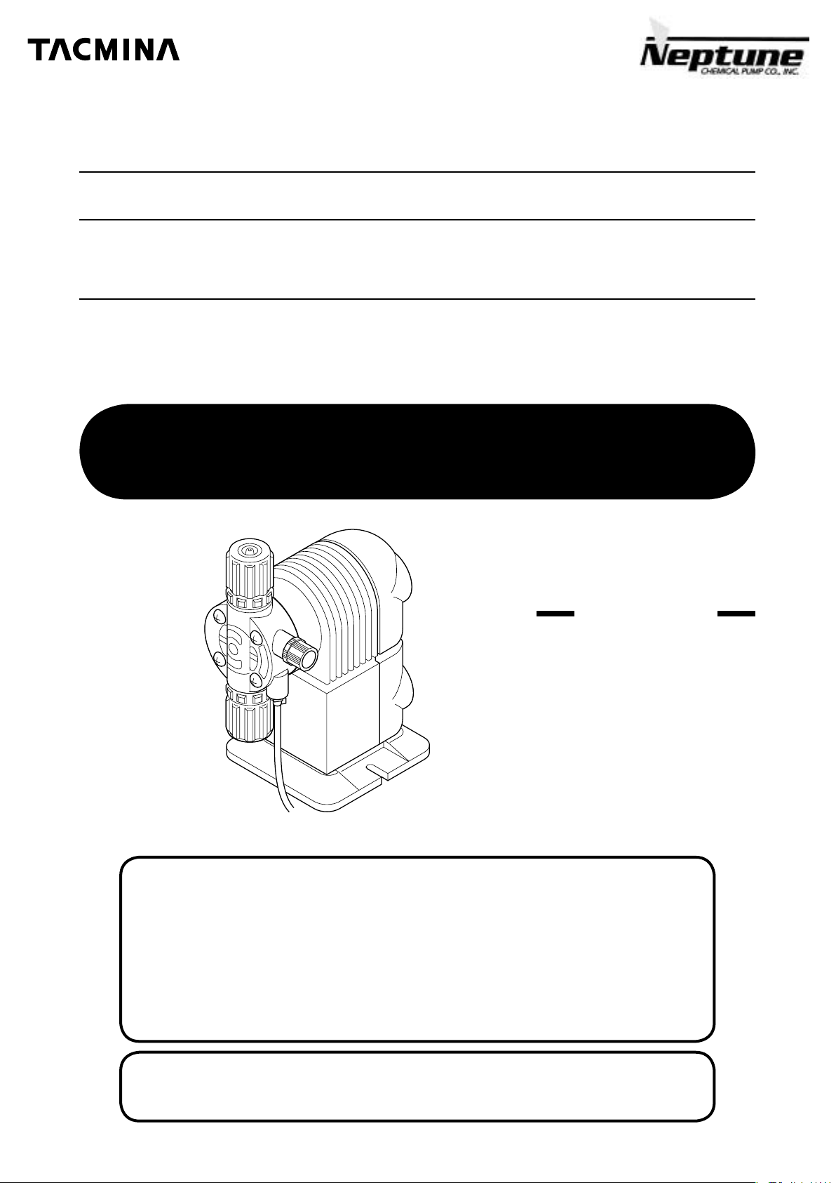
Solenoid-driven Diaphragm Metering Pump
PZ Series
OPERATION MANUAL
Please read this OPERATION MANUAL carefully before use.
Operating the pump incorrectly in disregard of these instructions
may lead to death, injury and/or cause property damage.
Applicable Models
PZ-31/61/12
ARPZ-31/61/12
This illustration is for PZ-31
7 Thank you for purchasing this TACMINA product. Please read this
OPERATION MANUAL carefully in order to ensure that you will use the
product safely and correctly.
7 Be sure to keep this OPERATION MANUAL in a place where it will be
easily available for reference.
7 If the product you purchased conforms to special specifications not
described in this OPERATION MANUAL, handle the product according to
details of separate meetings, drawings and approved documents.
7
TACMINA accepts no liability whatsoever for any damage caused by
malfunction of this product and other damage caused by use of this product.
www.tacmina.com
Page 2
How to operate the pump safely
In order to ensure that the pump will be operated correctly and safely, this OPERATION MANUAL contains some
guidelines for the user in the form of important safety precautions and considerations which, depending on their
seriousness, are categorized as set forth below. Be absolutely sure to heed these precautions and considerations.
WARNING
!
• This is used to indicate a condition or action which may result in death or serious injury if the instructions given
are ignored and the operations are performed incorrectly.
CAUTION
!
• This is used to indicate a condition or action which may result in injury and/or damage to personal property if
the instructions given are ignored and the operations are performed incorrectly.
IMPORTANT
• This is used to indicate a condition or action which must be established or carried out in order to maintain the
performance and service life of the equipment.
NOTE
• This is used to indicate supplementary information.
Conditions of Use
WARNING
!
• This pump cannot be used in explosion-proof regions or in explosive or combustible atmospheres.
CAUTION
!
• This pump must be used for the purpose of transferring or injecting liquids only. Using it for any other purpose may
result in accidents and/or malfunctions.
• This pump cannot be used to transfer or inject any liquids containing slurry.
• This pump’s discharge volume cannot be adjusted by operating the valve on its discharge pipe.
• The characteristics of this pump are such that pulsation will arise. If pulsation threatens to be a problem, install an
air chamber or some other device for reducing the effects of pulsation.
• Do not use the pump outside the following usage ranges. Doing so may cause malfunctions.
Ambient temperature
Ambient humidity
Temperature of liquid
Viscosity of liquid
Altitude of installation location
Transport and store the pump at temperatures within the −10°C to +50°C range. Do not subject the pump to strong impacts.
*
✽
Install the tank at a position higher than the pump (so that the pipe is connected to force the chemicals downward).
✽ The volume and viscosity of the liquids that can be pumped differ according to the conditions under which the pipes are
connected and the properties of the chemicals to be pumped.
0 to 40 °C*
35 to 85%RH
0 to 40 °C (no freezing)
Less than 50 mPa • s
Less than 1,000 m
Installation, Piping & Connections
WARNING
!
•
This pump does not have explosion-proof specifications. Do not install it in explosion-proof regions or in explosive or combustible atmospheres.
• Install the pump in a location that cannot be accessed by anyone but control personnel.
!
• If this pump has been dropped or damaged, consult your vender or a TACMINA representative. Using a dropped or
damaged pump may result in accidents and/or malfunctions.
• Do not install the pump where there is a risk of flooding or where there are high levels of moisture or dust. Doing so
may cause electric shocks and/or malfunctions.
•
This pump has a water-proof construction (equivalent to IP65 under IEC standards). However, it is made of plastic so make every attempt to
avoid installing it in a position that will shorten its service life (such as a position where it will be exposed to direct sunlight, wind or rain).
• Connect the pipes to the pump properly.
• Do not connect the pipes above a passageway. Do not install the pipes where the chemical may splash onto people
even if the hose/tube should break.
• When using a pump with a relief-valve function, always attach a hose for relief purposes, and lead the end of the
pipe back to a tank or other container.
CAUTION
1
Page 3
• When using a pump without a relief-valve function, be absolutely sure to install a relief valve on the pipe right
outside the pump on the discharge side. If the user has forgotten to open the valve or foreign matter is clogged
inside the pump’s discharge-side pipe, this may cause the pressure to rise above the pump’s specifications range,
liquid to gush out, the pipes to become damaged and/or the pump to malfunction, all of which are dangerous.
• When using the pump in cold regions, the chemical may freeze inside the pump head or pipes, possibly damaging
the pump and its surroundings. Be absolutely sure to install a heating unit or heat-insulating unit.
• The water used for the shipment tests may be left on the liquid-end parts (the parts that come into contact with the
liquid) of the pump. If the pump is to be used for chemical that may harden or give off gas if it reacts with water, be
absolutely sure to dry off the liquid-end parts prior to use.
• When the hoses/tubes become very hot, their ability to withstand pressure will deteriorate. When using hoses/tubes
available on the market, be absolutely sure to use the ones which are resistant to chemical and which can withstand
the temperatures and pressures under which the pump will be used.
•
The durability of a hose/tube differs significantly depending on the chemicals with which it is used, on the temperatures
and pressures and on the presence of ultraviolet rays. Inspect the hoses/tubes, and replace them if they have deteriorated.
Electrical Wiring
!
• This pump cannot be used in explosion-proof regions or in explosive or combustible atmospheres.
• Take steps to ensure that the power will not be turned on during the course of work. Hang a sign on the power
switch indicating that work is in progress.
• Do not operate the pump with wet hands. Doing so may result in electric shocks.
• Securely ground the protective earth terminal, and be absolutely sure to install a ground fault circuit interrupter.
Otherwise, you may receive electric shocks.
• Do not attempt to disassemble the pump body or the circuit parts.
!
• The wiring must be done by a qualified electrician or somebody with electrical knowledge.
•
Connect the wires after checking the supply voltage. Do not connect the wires to a power supply that is not within the rated voltage range.
WARNING
CAUTION
Operation & Maintenance
!
• Ensure that nobody other than the operators and control personnel will operate the pump.
• Take steps to ensure that the power will not be turned on during the course of work. Hang a sign on the power
switch indicating that work is in progress.
• Do not operate the pump with wet hands. Doing so may result in electric shocks.
•
When trouble has occurred (such as when smoke appears or there is a smell of burning), shut down the pump’s operation
immediately, and contact your vender or a TACMINA representative. Otherwise, a fire, electric shocks and/or malfunctions may result.
• Do not attempt to disassemble the pump body or the circuit parts.
• During the air releasing, chemical may suddenly gush out from the pipes and other parts. Lead the end of the airrelease hose bank to the tank or other container, and secure it so that it will not become disconnected.
•
A situation in which the valve inside the pipe at the discharge side of the pump is shut off or becomes blocked with foreign matter
is dangerous in that it may lead to an excessive rise in pressure that will exceed the pump’s specification range, causing liquid to
gush out, the pipe to be damaged and the pump itself to malfunction. Prior to operating the pump, check the valves and pipes, etc.
WARNING
CAUTION
!
• When working on the liquid-end parts of the pump, wear protective gear suited to the chemical concerned (such as
rubber gloves, a mask, protective goggles and work overalls that are resistant to chemical).
• Before attempting to maintain or repair the pump, release the pressure in the discharge pipe, discharge the liquid in
the pump head, and clean the liquid-end parts.
• The vibration of the pump may cause the hoses/tubes to become loose and disconnected. Before starting
operation, secure the hoses/tubes and check their tightness.
• While the pump is operating, the pump’s surfaces may become hot, reaching a temperature of 60°C or more.
• Idling the pump for prolonged periods of time can lead to malfunctions.
Other Precautions
CAUTION
!
• Do not attempt to remodel the pump.
• Install a protective barrier or other preventive action to cope with a chemical spill just in case one occurs. Also take
steps to ensure that the pump will not get wet from the chemical.
• When it comes time to dispose of the pump, entrust its disposal to an industrial waste disposal company whose
operations have been authorized in accordance with applicable laws and regulations.
2
Page 4

Page 5

Introduction
Contents
Checking out the product
Accessories list
Description of product
Names of the parts
............................................................................................................................
.......................................................................................................................
............................................................................................................
.................................................................................................................
Installation
Installing the product
Piping
Connecting
Electrical wiring
............................................................................................................................................
✽
The instructions differ according to the model. Find the model concerned in the table on page 9, and read the instructions given.
✽ The instructions differ according to the model. Find the model concerned in the table on page 14, and read the instructions given.
..................................................................................................................................
...................................................................................................................
..........................................................................................................................
Operation
Operating precautions
Air releasing
Discharge-volume setting
Procedure for prolonged shutdown of operation
................................................................................................................................
...............................................................................................................
..........................................................................................................
Maintenance
....................................................................
5
5
7
7
8
9
InstallationOperationMaintenance
14
23
25
26
28
28
Maintenance precautions
Replacing the diaphragm
Replacing the valve seats and check balls
Replacing the relief valve
..........................................................................................................
..........................................................................................................
..........................................................................................................
Troubleshooting
Troubleshooting
.........................................................................................................................
Specifications
Model code
Liquid-end material
Specification
Performance curve
External dimension
..................................................................................................................................
....................................................................................................................
...............................................................................................................................
.....................................................................................................................
....................................................................................................................
Others
Consumables
Spare parts & options
Explanation of terms
After-sales services
..............................................................................................................................
................................................................................................................
..................................................................................................................
...................................................................................................................
..............................................................................
29
30
31
35
37
39
42
43
47
49
51
53
53
54
Troubleshooting
Specifications
Others Introduction
4
Page 6
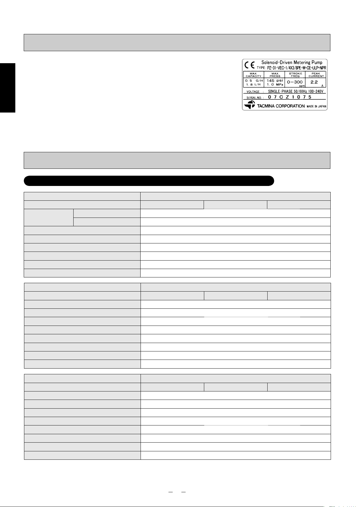
Checking out the product
After unpacking the pump, check the following.
• Is the pump the one that was ordered?
• Do the details on the pump’s nameplate match what was ordered?
• Is all the accessories supplied?
✽ Check the supplied accessories against the “Accessories list” below.
• Has the pump sustained any damage from vibration or impact during transit?
• Have any of the screws come loose or fallen out?
Introduction
Every care is taken by TACMINA in the shipment of its pumps, but if you
come across anything untoward, please contact your vender or a TACMINA
representative.
Accessories list
Model for injection of general chemicals: PZ-31/61/12-VEC/VFC/FEC/FFC/FTC
Liquid-end Material VEC/VFC
Model 31 61 12
Hose/tube
Relief/air-release hose (1m, installed) Soft PVC hose (4×6)
INSULOK (spare) for relief/air-release hose 1 piece
Anti-siphon check valve 1 set (R1/2)
Foot valve 1 set
Pump-mounting nuts/bolts 2 sets (M5×30)
Operation manual 1 copy
Discharge side (3m) PE tube (1/4"×3/8")
Suction side (2m) PVC braided hose (1/4"×3/8")
Liquid-end Material FEC/FFC
Model 31 61 12
Tube (5m) PE tube (1/4"×3/8")
Relief/air-release hose (1m, installed) Soft PVC hose (4×6)
INSULOK (spare) for relief/air-release hose 1 piece
Anti-siphon check valve 1 set (R1/2)
Foot valve 1 set
Ceramic weight 1 set
Pump-mounting nuts/bolts 2 sets (M5×30)
Operation manual 1 copy
Liquid-end Material FTC
Model 31 61 12
Tube (5m) FEP tube (1/4"×3/8")
Relief/air-release hose (1m, installed) Soft PVC hose (4×6)
INSULOK (spare) for relief/air-release hose 1 piece
Anti-siphon check valve 1 set (R1/2 or R3/8)
Foot valve 1 set
Ceramic weight 1 set
Pump-mounting nuts/bolts 2 sets (M5×30)
Operation manual 1 copy
5
Page 7
Accessories list
Model for injection of boiler chemicals: PZ-31-FEC (PP)
Liquid-end Material FEC (PP)
Model 31
Tube
Relief/air-release hose (1m, installed) Soft PVC hose (4×6)
INSULOK (spare) for Relief/air-release hose 1 piece
Anti-siphon check valve 1 set (R1/2)
Foot valve 1 set
Ceramic weight 1 set
Pump-mounting nuts/bolts 2 sets (M5×30)
Operation manual 1 copy
Model for injection of sodium hypochlorite: PZ-31/61/12-CL
Hose/tube
Air-release hose (1m) Soft PVC hose (4×6)
Anti-siphon check valve w/ duck-bill cap 1 set (R1/2)
Foot valve 1 set
Pump-mounting nuts/bolts 2 sets (M5×30)
Operation manual 1 copy
Discharge side (3m) PP tube (1/8"×1/4")
Suction side (2m) PE tube (1/4"×3/8")
Liquid-end Material CL
Model 31 61 12
Discharge side (3m) PE tube (1/4"×3/8")
Suction side (2m) PVC braided hose (1/4"×3/8")
Introduction
Model w/ automatic air-release function for injection of sodium hypochlorite: ARPZ-31/61/12
Liquid-end Material CL
Model 31 61 12
Hose/tube
Air-release hose (1m) Soft PVC hose (4×6)
Anti-siphon check valve w/ duck-bill cap 1 set (R1/2)
Foot valve 1 set
Pump-mounting nuts/bolts 2 sets (M5×30)
Operation manual 1 copy
Discharge side (3m) PE tube (1/4"×3/8")
Suction side (2m) PVC braided hose (1/4"×3/8")
6
Page 8
Description of product
This is a solenoid-driven diaphragm metering pump with liquid-end parts which are resistant to chemicals and with a
compact body. It can be operated on any supply voltage from AC 100V to AC 240V (±10%). Its discharge capacity has
been adjusted so that it will remain constant over the supply voltage range.
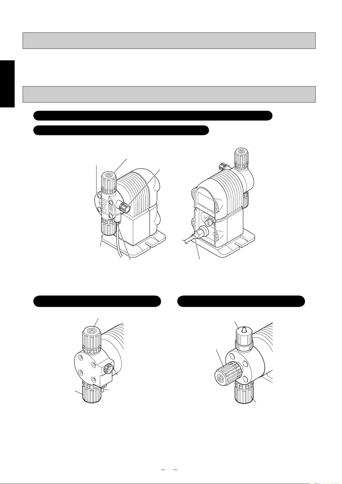
Names of the parts
Introduction
Model for injection of general chemicals: PZ-31/61/12-VEC/VFC/FEC/FFC/FTC
Model for injection of boiler chemicals: PZ-31-FEC (PP)
Pump head
Discharge-side joint
Relief valve
Suction-side joint
Relief/air-release port
✽ The shapes of pump heads and joints differ slightly depending on the liquid-end material and connection type.
Model for injection of sodium hypochlorite:
PZ-31/61/12-CL
Discharge-side joint
Air-release knob
Suction-side joint
Air-release port
Cable ground
Model w/ automatic air-release funtion
injection of sodium hypochlorite: ARPZ-31/61/12
Air-release joint
Discharge-side joint
Suction-side joint
for
7
Page 9

Installing the product
WARNING
!
• This pump does not have explosion-proof specifications. Do not install it in explosion-proof regions or
in explosive or combustible atmospheres.
• Install the pump in a location that cannot be accessed by anyone but control personnel.
!
• Do not install the pump where there is a risk of flooding or where there are high levels of moisture or
dust. Doing so may cause electric shocks and/or malfunctions.
• This pump has a water-proof construction (equivalent to IP65 under IEC standards). However, it is made
of plastic so make every attempt to avoid installing it in a position that will shorten its service life (such
as a position where it will be exposed to direct sunlight, wind or rain).
CAUTION
Installation location
• Avoid installing the pump in a location exposed to direct sunlight or wind and rain. Although it features a water-proof
construction (equivalent to IP65 under the IEC standards), direct sunlight may cause the temperature of the metal
parts to rise, ultraviolet rays may cause the plastic parts to deteriorate, and sand, dust, and rainwater may damage or
corrode the pump body. When installing the pump outdoors, it is recommended that an awning or cover be installed to
protect the pump from the elements and extend its service life.
• Install the pump in a location where the ventilation is good and where the chemical will not freeze.
• Provide adequate space around the pump to facilitate maintenance and inspections.
• Place the pump in a level location, and secure it so that it will not vibrate. Installing the pump at an angle may result in
discharge trouble or in the inability of pump to discharge.
Installation
Mounting bolt positions
Use the pump-mounting bolts (×2) provided to secure the pump.
✽ The pump can be installed at any pitch ranging from 87 to 110 mm.
8
Page 10
Piping
!
• Connect the pipes to the pump properly.
• Do not connect the pipes above a passageway. Do not install the pipes where the chemical may splash
onto people even if the hose/tube should break.
• When using a pump with a relief-valve function, always attach a hose for relief purposes, and lead the
end of the pipe back to a tank or other container.
• When using a pump without a relief-valve function, be absolutely sure to install a relief valve on the
pipe right outside the pump on the discharge side. If the user has forgotten to open the valve or foreign
matter is clogged inside the pump’s discharge-side pipe, this may cause the pressure to rise above
the pump’s specifications range, liquid to gush out, the pipes to become damaged and/or the pump to
malfunction, all of which are dangerous.
•
When using the pump in cold regions, the chemical may freeze inside the pump head or pipes, possibly
damaging the pump and its surroundings. Be absolutely sure to install a heating unit or heat-insulating unit.
•
Installation
When the hoses/tubes become very hot, their ability to withstand pressure will deteriorate. When using
hoses/tubes available on the market, be absolutely sure to use the ones which are resistant to chemical
and which can withstand the temperatures and pressures under which the pump will be used.
•
The durability of a hose/tube differs significantly depending on the chemicals with which it is used, on the temperatures
and pressures and on the presence of ultraviolet rays. Inspect the hoses/tubes, and replace them if they have deteriorated.
IMPORTANT
• Install a pressure gauge on the discharge-side pipe in order to measure the pressure at the discharge
side of the pump.
• Install the pump as close as possible to the tank. If the suction-side pipe is too long, cavitation* may
occur, possibly making it impossible to maintain the pump’s metering capability.
* Refer to the “Explanation of terms” on page 53.
CAUTION
■Pulsation
• The occurrence of pulsation will cause the pump’s hoses/tubes to vibrate. Secure the hoses/tubes so that they will not
swing about.
• In order to reduce pulsation, the installation of a damper is recommended. Ask a TACMINA representative for more
information.
■Pipe length
• An excessively long hose/tube may result in increased pressure loss, may cause the pressure to exceed the pump’s
allowable pressure, or may give rise to overfeed and/or cause pipe vibration.
• The pump comes with a 5-meter-long hose/tube for both the discharge side and suction side. If the pressure loss
exceeds the pump’s maximum discharge pressure, thicker pipes will be required. Provide details on the (1) viscosity
of the liquid, (2) length of the pipes (how they are positioned) and (3) specific gravity of the liquid to a TACMINA
representative.
■During maintenance
• When disconnecting the hose/tube for maintenance or other purposes and then reconnecting the same hose/tube, cut
about 10 mm off the end of the hose/tube before reconnecting.
• When conducting maintenance, release the pressure of the discharge hose/tube.
■When curving a hose/tube
• Provide a sufficient margin so that the hose/tube will not bend instead of curve round.
• Take steps to ensure that the hose/tube will not bend, rub against other parts, be cut or stepped on. Such actions can
damage the hose/tube.
• Take steps to minimize the number of tight curves in the pipes, joints and other parts that may restrict the flow.
The piping procedure will be described by pump type.
Model Series Page
Model for injection of general chemicals PZ-31/61/12-VEC/VFC/FEC/FFC/FTC 10
Model for injection of boiler chemicals PZ-31-FEC (PP) 11
Model for injection of sodium hypochlorite PZ-31/61/12-CL 12
Model w/ automatic air-release function for injection of
sodium hypochlorite
ARPZ-31/61/12 13
9
Page 11

Piping
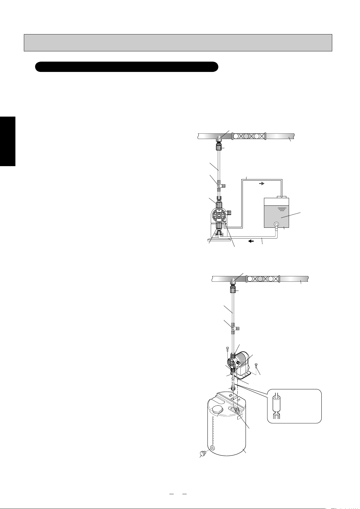
Model for injection of general chemicals: PZ-31/61/12-VEC/VFC/FEC/FFC/FTC
Installation is described with an example using PZ-31-VEC and TACMINA tank.
• If the valve has not been opened or clogging by foreign matter has occurred inside the pipe at the discharge side of
the pump, the chemical will gush out from the relief/air-release port. Therefore, always have a relief/air-release hose
installed, and lead its end back into the tank or other container.
• Install a valve for releasing abnormal pressure that has built up inside the discharge-side pipe. The 3-way valve on the
washing water line may be used instead.
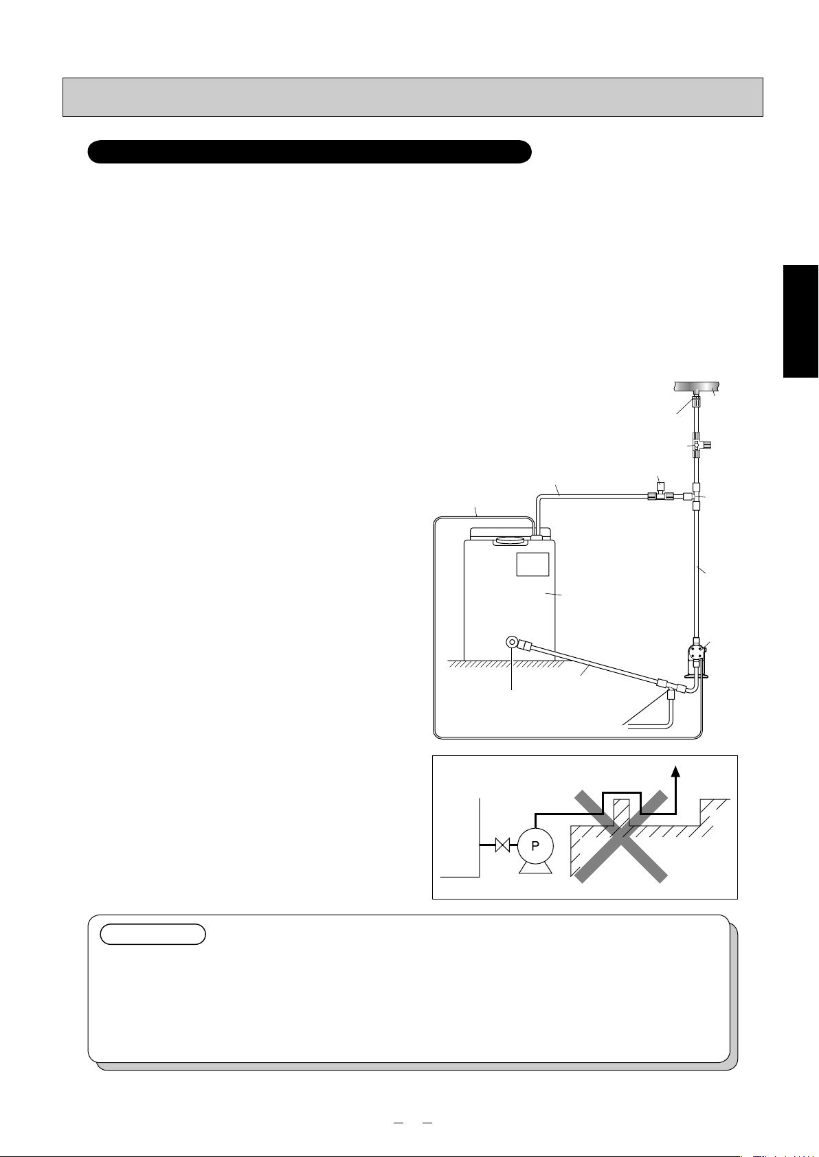
■ When installing the pump
below the tank
(1)
Connect the suction valve of the tank and the suctionside joint of the pump using the hose/tube.
(2) Connect the discharge-side joint of the pump and
main pipe (injection point) using the tube. When
doing this, attach the anti-siphon check valve at the
injection-point side end of the tube.
(3) Return the end of the relief/air-release hose which
has already been attached to the relief/air-release
port to the tank or other container.
✽ It is also recommended that a valve, meter, etc. be
installed to make it easy to carry out maintenance
and other such jobs.
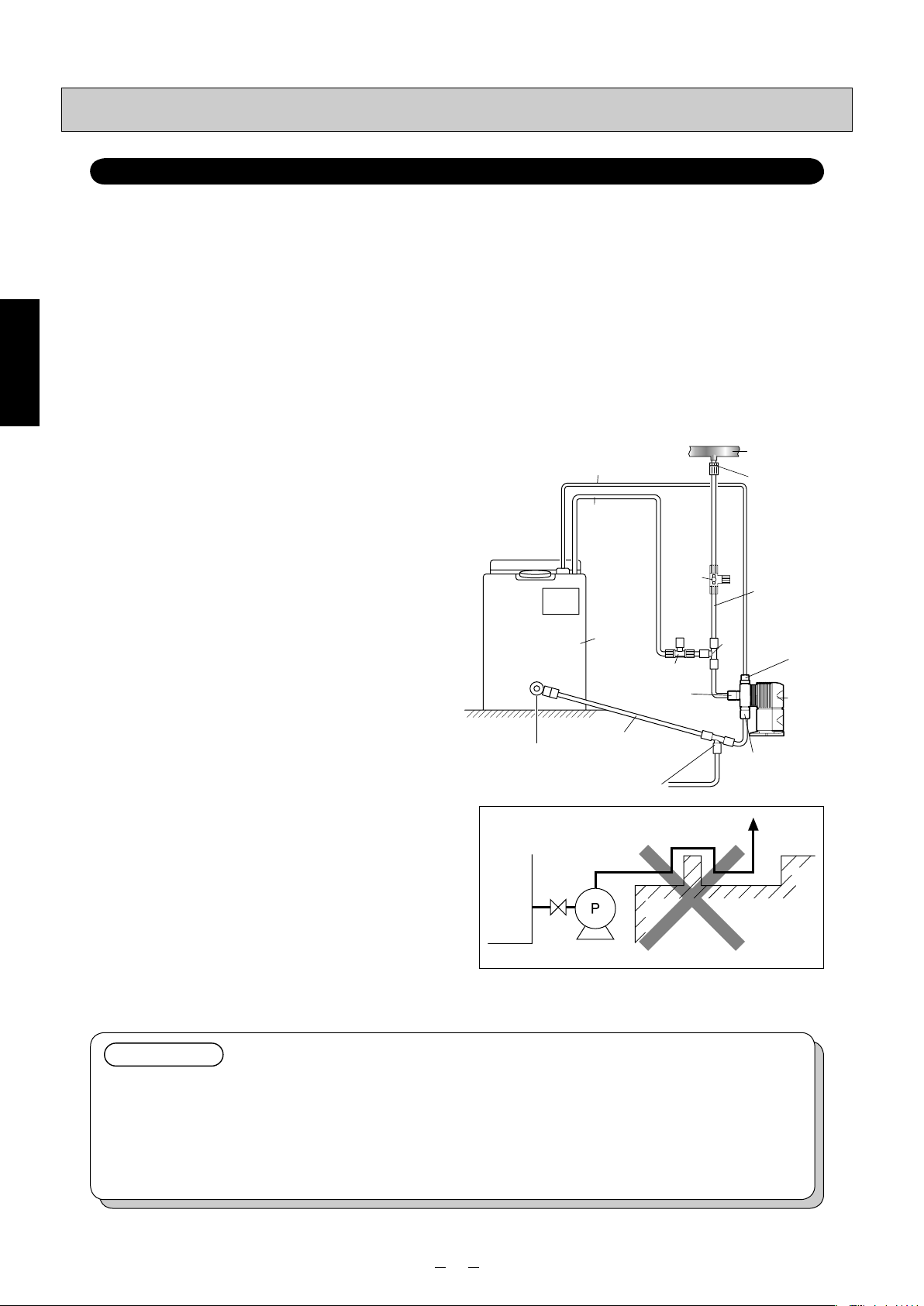
■ When installing the pump
above the tank
(1) Using the pump-mounting bolts provided, secure the
pump to the prescribed position on top of the tank.
(2) Pass the suction-side hose/tube with foot valve and
ceramic weight (tube only) attached through the
hole in the suction-pipe cover on top of the tank, and
connect it to the suction-side joint of the pump. At
this time, adjust the length of the hose/tube and cut
it so that the foot valve is 30 mm higher than the bottom of the tank.
(3) Connect the discharge-side joint of the pump and
main pipe (injection point) using the tube. When
doing this, attach the anti-siphon check valve at the
injection-point side end of the tube.
(4) Return the end of the relief/air-release hose which
has already been attached to the relief/air-release
port to the tank or other container.
✽ Installing the pump above the tank is not recommend-
ed for chemicals in which air bubbles tend to form.
✽ This pump’s static suction head is −1.5 m for water.
Its suction capability may decrease when the valve
seats inside the pump head are dry.
✽ Be absolutely sure to connect the foot valve provided
to the end of the suction-side hose/tube to prevent
dirt or foreign matter from entering the pump head
and valve seat area.
✽ It is also recommended that a valve, meter, etc. be
installed to make it easy to carry out maintenance
and other such jobs.
Dischargeside pipe
3-way valve
Dischargeside joint
Suction-side joint
Dischargeside pipe
3-way valve
Suction-side joint
Suction-side pipe
Foot valve
Drain cock
Injection point
Anti-siphon check valve
Relief/air-release hose
UP
PVC
Relief/air-release port
Injection point
Anti-siphon check valve
Discharge-side joint
Relief/air-release port
Pump-mounting bolts (2 sets)
Relief/air-release hose
Tank
Tank
Suction-side pipe
When a PE or FEP tube is
to be used for the suction
side pipe (FEC/FFC/FTC
only), attach the ceramic
weight (supplied) to
straighten the tube.
Suction-pipe cover
Main pipe
Installation
Suction valve
Main pipe
10
Page 12
Piping
Model for injection of boiler chemicals: PZ-31-FEC (PP)
Installation is described with an example using PZ-31-FEC (PP) and TACMINA tank.
• If the valve has not been opened or clogging by foreign matter has occurred inside the pipe at the discharge side of
the pump, the chemical will gush out from the relief/air-release port. Therefore, always have a relief/air-release hose
installed, and lead its end back into the tank or other container.
• Install a valve for releasing abnormal pressure that has built up inside the discharge-side pipe. The 3-way valve on the
washing water line may be used instead.
■ When installing the pump
below the tank
(1)
Connect the suction valve of the tank and the suctionside joint of the pump using the tube.
Installation
(2) Connect the discharge-side joint of the pump and
main pipe (injection point) using the tube. When
doing this, attach the anti-siphon check valve at the
injection-point side end of the tube.
(3) Return the end of the relief/air-release hose which
has already been attached to the relief/air-release
port to the tank or other container.
✽ It is also recommended that a valve, meter, etc. be
installed to make it easy to carry out maintenance
and other such jobs.
■ When installing the pump
above the tank
(1) Using the pump-mounting bolts provided, secure the
pump to the prescribed position on top of the tank.
(2) Pass the suction-side tube with foot valve and
ceramic weight attached through the hole in the
suction-pipe cover on top of the tank, and connect
it to the suction-side joint of the pump. At this time,
adjust the length of the tube and cut it so that the
foot valve is 30 mm higher than the bottom of the
tank.
(3) Connect the discharge-side joint of the pump and
main pipe (injection point) using the tube. When
doing this, attach the anti-siphon check valve at the
injection-point side end of the tube.
(4) Return the end of the relief/air-release hose which
has already been attached to the relief/air-release
port to the tank or other container.
✽ Installing the pump above the tank is not recommend-
ed for chemicals in which air bubbles tend to form.
✽ This pump’s static suction head is −1.5 m for water.
Its suction capability may decrease when the valve
seats inside the pump head are dry.
✽ Be absolutely sure to connect the foot valve provided
to the end of the suction-side hose to prevent dirt
or foreign matter from entering the pump head and
valve seat area.
✽ It is also recommended that a valve, meter, etc. be
installed to make it easy to carry out maintenance
and other such jobs.
Injection point
Anti-siphon check valve
Dischargeside pipe
3-way valve
Dischargeside joint
UP
PVDF
Suction-side joint Suction-side pipe
Suction-side joint
Suction-side pipe
Drain cock
Relief/air-release port
Dischargeside pipe
3-way valve
Foot valve
Relief/air-release hose
Tank
Injection point
Anti-siphon check valve
Discharge-side joint
Relief/air-release port
Pump-mounting bolts (2 sets)
Relief/air-release hose
Suction-pipe cover
Tank
Main pipe
Suction valve
Main pipe
Attach the ceramic
weight (supplied) to
straighten the tube.
11
Page 13
Piping
Model for injection of sodium hypochlorite: PZ-31/61/12-CL
Installation is described with an example using PZ-31-CL and TACMINA tank.
• It is extremely dangerous for the user to forget to open the valve or for there to be the clogging of foreign matter inside
the pump’s discharge-side pipe. Be absolutely sure to install a relief valve, which will automatically release abnormally
high pressure levels, on the discharge-side pipe.
• Install a valve for releasing abnormal pressure that has built up inside the discharge-side pipe. The 3-way valve on the
washing water line may be used instead.
• To prevent gas lock and other such types of trouble, be absolutely sure to use the pump with a push-in pipe (when the
pump is to be placed lower than the tank).
• In order to prevent gas lock caused by gases generated and building up inside the pipes, make the pipe connections
as short as possible.
■ When installing the pump
below the tank
✽ Do not install the pump above the tank.
(1)
Connect the suction valve of the tank and the suctionside joint of the pump using the hose. When doing
this, tilt the pipe at a downward gradient so that no air
will be trapped inside the pipe.
(2) Connect the tube to the discharge-side joint of the
pump.
(3) Attach a 3-way joint to the discharge-side tube (near
the pump’s discharge-side joint), and install a relief
valve. Return the end of the relief pipe to the tank or
other container.
(4) Connect the end of the other discharge-side tube
extending from the 3-way joint to the main pipe
(injection point). When doing this, attach the antisiphon check valve with duck-bill cap at the injection-point side end of the tube.
(5) Attach one end of the air-release hose to the air-
release port, and return the other end to the tank or
other container.
✽ If it is unavoidable for the pump to be placed higher
than the tank, be absolutely sure to connect the foot
valve supplied to the end of the suction-side hose
to ensure that no dirt or foreign matter will be mixed
inside the pump head or valve seat.
✽ It is also recommended that a valve, meter, etc. be
installed to make it easy to carry out maintenance
and other such jobs.
Anti-siphon
check valve
w/ duck-bill cap
3-way valve
Relief valve
Air-release hose
Suction valve
Relief pipe
Ta nk
Suction-side pipe
(downward gradient)
Draining of washing water
<Example of unacceptable installation>
Main pipe
3-way joint
Dischargeside pipe
Metering
pump
Installation
Metering pump
IMPORTANT
<Washing water line>
• It is recommended that a washing water line be provided in the piping.
(A 3-way valve for releasing abnormally high pressure levels may be used instead.)
<Sodium hypochlorite>
•
Take steps to use up the sodium hypochlorite in as short a period as possible (10 to 20 days in hot weather).
• When diluting sodium hypochlorite, use (1) pure water (purified water), (2) water that has been passed
through a water softener or (3) city water that has been purified.
12
Page 14
Piping
Model w/ automatic air-release function for injection of sodium hypochlorite: ARPZ-31/61/12
Installation is described with an example using ARPZ-31 and TACMINA tank.
•
Unlike other models, this pump has a discharge-side joint at the front of the pump head and an air-release side joint on its top.
• It is extremely dangerous for the user to forget to open the valve or for there to be the clogging of foreign matter inside
the pump’s discharge-side pipe. Be absolutely sure to install a relief valve, which will automatically release abnormally
high pressure levels, on the discharge-side pipe.
• Install a valve for releasing abnormal pressure that has built up inside the discharge-side pipe. The 3-way valve on the
washing water line may be used instead.
• To prevent gas lock and other such types of trouble, be absolutely sure to use the pump with a push-in pipe (when the
pump is to be placed lower than the tank).
• In order to prevent gas lock caused by gases generated and building up inside the pipes, make the pipe connections
as short as possible.
Installation
■ When installing the pump
below the tank
✽ Do not install the pump above the tank.
(1)
Connect the suction valve of the tank and the suctionside joint of the pump using the hose. When doing
this, tilt the pipe at a downward gradient so that no air
will be trapped inside the pipe.
(2) Connect the tube to the discharge-side joint of the
pump.
(3) Attach a 3-way joint to the discharge-side tube (near
the pump’s discharge-side joint), and install a relief
valve. Return the end of the relief pipe to the tank or
other container.
(4) Connect the end of the other discharge-side tube
extending from the 3-way joint to the main pipe
(injection point). When doing this, attach the antisiphon check valve with duck-bill cap at the injection-point side end of the hose/tube.
(5) Attach one end of the air-release hose to the air-
release port, and return the other end to the tank or
other container.
✽ If it is unavoidable for the pump to be placed higher
than the tank, be absolutely sure to connect the foot
valve supplied to the end of the suction-side hose
to ensure that no dirt or foreign matter will be mixed
inside the pump head or valve seat.
✽ It is also recommended that a valve, meter, etc. be
installed to make it easy to carry out maintenance
and other such jobs.
Air-release hose
Relief pipe
3-way
valve
Tank
Relief valve
Discharge-side joint
Suction valve
Draining of washing water
Suction-side pipe
(downward gradient)
<Example of unacceptable installation>
Main pipe
Anti-siphon
check valve
w/ duck-bill cap
Dischargeside pipe
3-way
Air-release joint
joint
Suction-side joint
Metering
pump
Metering pump
IMPORTANT
<Washing water line>
• It is recommended that a washing water line be provided in the piping.
(A 3-way valve for releasing abnormally high pressure levels may be used instead.)
<Sodium hypochlorite>
•
Take steps to use up the sodium hypochlorite in as short a period as possible (10 to 20 days in hot weather).
• When diluting sodium hypochlorite, use (1) pure water (purified water), (2) water that has been passed
through a water softener or (3) city water that has been purified.
13
Page 15
Connecting
The connection procedure will be described by pump type.
Model Liquid-end material Hose/tube Page
Discharge side : PE tube
Suction side : PVC braided hose
14
Model for injection of general chemicals
PZ-31/61/12-VEC/VFC
PZ-31/61/12-FEC/FFC PE tube
16
PZ-31/61/12-FTC FEP tube
Model for injection of boiler chemicals PZ-31-FEC (PP)
Model for injection of sodium hypochlorite
Model w/ automatic air-release function
for injection of sodium hypochlorite
PZ-31/61/12-CL
ARPZ-31/61/12
Discharge side : PP tube
Suction side : PE tube
Discharge side : PE tube
Suction side : PVC braided hose
Discharge side : PE tube
Suction side : PVC braided hose
18
20
21
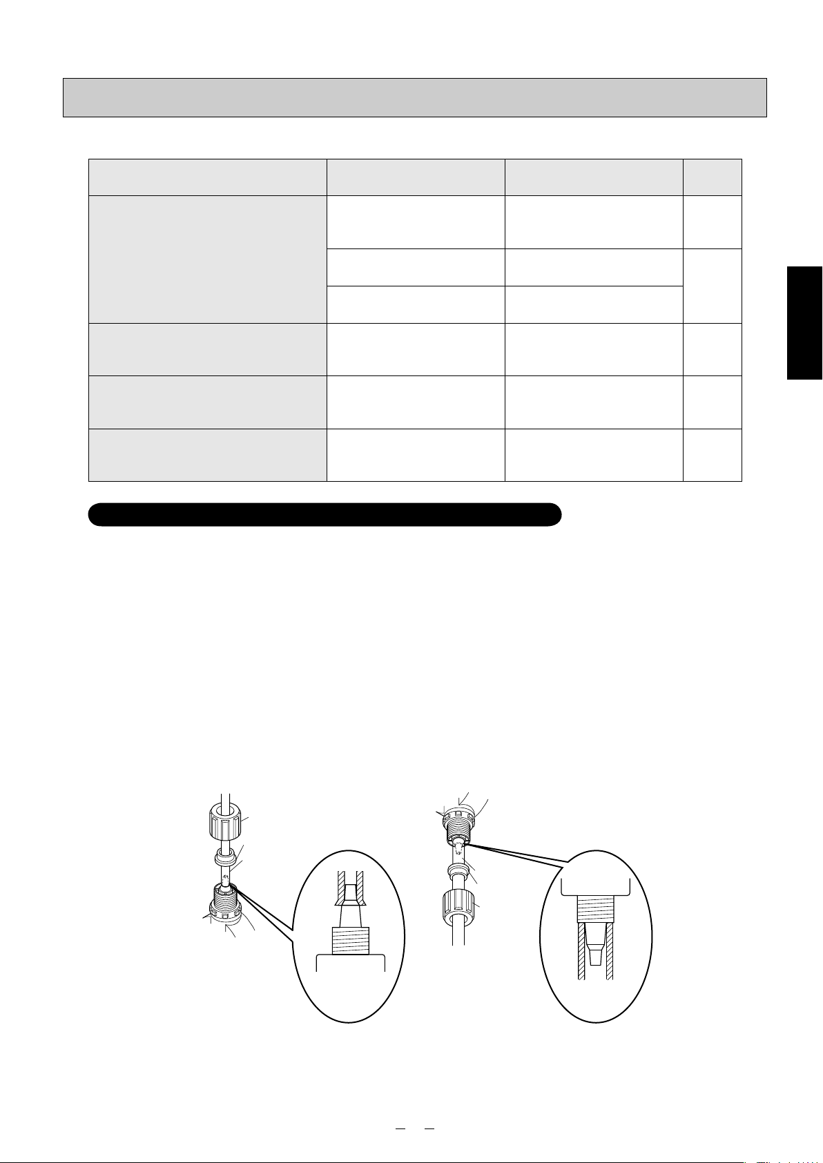
Model for injection of general chemicals: PZ-31/61/12-VEC/VFC
■PVC braided hose/PE tube
• When bending the hose/tube, provide sufficient leeway in the bending so that the hose/tube will not break. Also ensure that it will not be rubbed against or trodden on.
• Insert the hose/tube firmly so that it will not become disconnected, and tighten the nuts securely. Do not excessively
tighten the nuts. Doing so may damage or break the joint.
• If the temperature of a liquid or ambient temperature is higher than room temperature, the tightening force will be reduced, and the hose/tube may become disconnected. After operation has started, tighten up the nuts as appropriate.
• When tightening the nuts, hold the hose/tube to prevent it from being twisted. The joints and other areas may be loosened by the return force of the hose/tube.
• The pump comes with a 5-meter long hose/tube for both the discharge side and suction side. When longer hose/tube
is used, the pressure loss may exceed the pump’s maximum discharge pressure so thicker hose/tube will be required.
Provide details on the (1) viscosity of the liquid, (2) length of the pipes (how they are positioned) and (3) specific gravity of the liquid to a TACMINA representative who will select the appropriate hose/tube size.
• When disconnecting the hose/tube for jobs such as maintenance and then afterwards re-connecting the same hose/
tube, cut about 10 mm off the end of the hose/tube before re-using them.
Installation
Nut
Retaining ring
PE tube
PE tube
(1/4”×3/8”)
14
PVC braided hose
Retaining ring
Nut
PVC braided hose
(1/4”×3/8”)
Page 16
Connecting
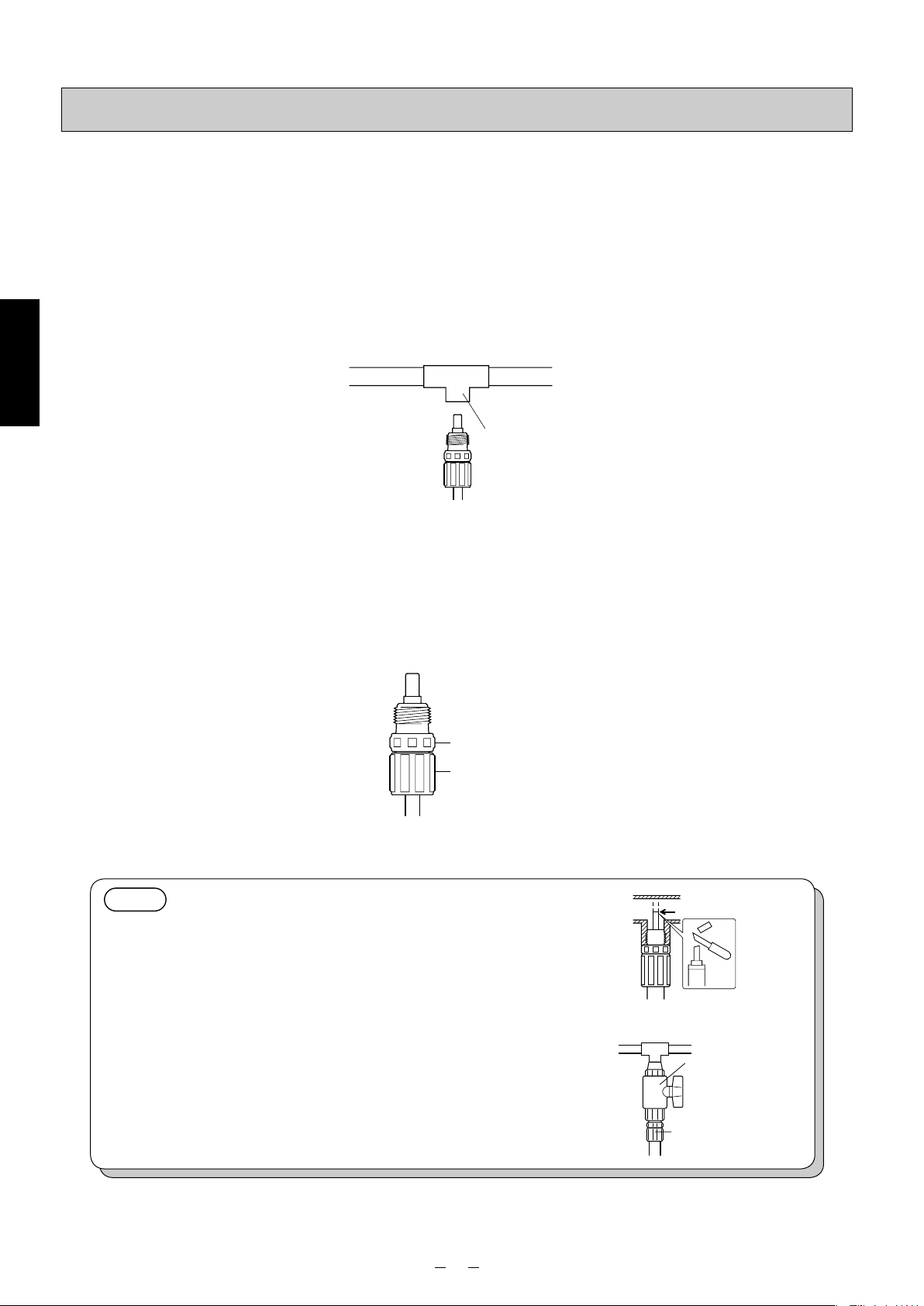
■Anti-siphon check valve
This pump is provided with an anti-siphon check valve. Use this valve at the injection point unless there is a good reason not to do so. Be absolutely sure to install it in the following cases.
• When the injection point is open to the atmosphere and liquid is to be injected at a position lower than the level of the
liquid in the tank (prevention of siphoning)
• When the liquid is to be injected inside the suction-side pipe of a volute pump, etc.
• When a chemical greatly exceeding the pump’s rated discharge volume is being fed (prevention of overfeed)
✽ Even with a rising pipe, overfeed may occur if the pipe is too long.
(1) The anti-siphon check valve has an R1/2 external thread. Provide an Rc1/2 internal thread at the injection point.
Installation
(2)
Wind sealing tape around the external thread of the anti-siphon check valve, and screw the valve into the injection point.
✽ If it is hard to screw the valve in, grasp the nozzle grip using a tool such as pliers, and tighten the valve gently.
✽ When connecting the tube with the anti-siphon check valve already mounted on it to the main pipe, be absolutely
sure to hold the valve body and turn the nut. If the nut is turned without holding the body, the threaded part on the
nozzle may be damaged.
Main pipe
Injection point
(Rc1/2)
Nozzle grip
Nut
NOTE
<When injecting liquid into a pipe with a small diameter>
If the end of the anti-siphon check valve is too long, cut it off
so that the end will be positioned at the center of the main pipe
where the chemical is to be injected prior to use.
<For maintenance>
It is recommended that the tube be attached to the main pipe
through a valve to enable the anti-siphon check valve to be
replaced or cleaned, etc.
✽ Use a valve made of materials which will resist any corrosion
resulting from the chemical used.
Valve
Anti-siphon
check valve
15
Page 17
Connecting
Model for injection of general chemicals: PZ-31/61/12-FEC/FFC/FTC
■PE/FEP tube
• When bending the tube, provide sufficient leeway in the bending so that the tube will not break. Also ensure that it will
not be rubbed against or trodden on.
• Insert the tube firmly so that it will not become disconnected, and tighten the nuts securely. Do not excessively tighten
the nuts. Doing so may damage or break the joint.
• If the temperature of a liquid or ambient temperature is higher than room temperature, the tightening force will be
reduced, and the tube may become disconnected. After operation has started, tighten up the nuts as appropriate.
• When tightening the nuts, hold the tube to prevent it from being twisted. The joints and other areas may be loosened
by the return force of the tube.
• The pump comes with a 5-meter long tube for both the discharge side and suction side. When longer tube is used, the
pressure loss may exceed the pump’s maximum discharge pressure so thicker tube will be required. Provide details
on the (1) viscosity of the liquid, (2) length of the pipes (how they are positioned) and (3) specific gravity of the liquid
to a TACMINA representative who will select the appropriate tube size.
• When disconnecting the tube for jobs such as maintenance and then afterwards re-connecting the same tube, cut
about 10 mm off the end of the tube before re-using it.
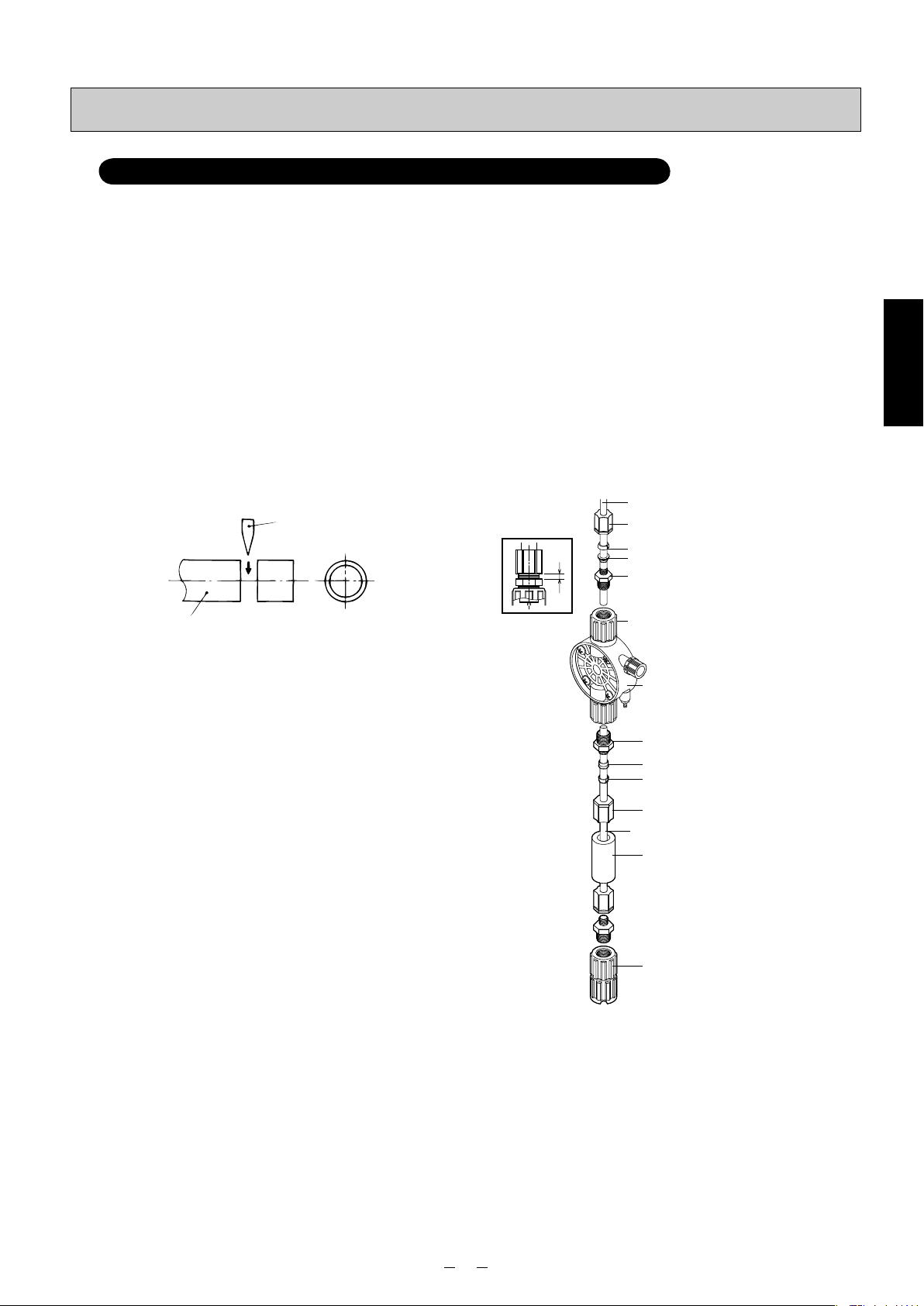
(1) Cut the end of the tube at right angles using a sharp
blade.
blade
a
PE/FEP tube (1/4”×3/8”)
Nut (A)
Grip (B)
⎫
Sleeve (C)
Tube-fitting body (D)
⎬
Installation
tube
(2) Wrap sealing tape around the tube-fitting body (D),
and screw the body into the discharge-side joint
using a tool. (The tube-fitting body is already mounted in place before shipment.)
(3)
Pass the tube through the nut (A), grip (B) and
sleeve (C), and insert its end until it touches the
back end of the tube-fitting body (D) on the inside.
(4) Tighten the nut (A) by hand.
(5) Using the tool, tighten the nut (A) in such a way that
the gap (area “a” in the figure) between the tube-
fitting body (D) and nut (A) is approximately 1.5 mm.
✽ Bear in mind that the joint may break if the nut (A)
is tightened too much.
Discharge-side joint
⎭
Pump head
Tube-fitting body
Sleeve
Grip
Nut
PE/FEP tube (1/4”×3/8”)
Ceramic weight (E)*
Foot valve
* The tube is packed in the form of a coil. Attach the
ceramic weight (E) and straighten out the tube so that
the liquid inside the tank will be sucked up through it.
16
Page 18

Connecting
■Anti-siphon check valve
This pump is provided with an anti-siphon check valve. Use this valve at the injection point unless there is a good reason not to do so. Be absolutely sure to install it in the following cases.
• When the injection point is open to the atmosphere and liquid is to be injected at a position lower than the level of the
liquid in the tank (prevention of siphoning)
• When the liquid is to be injected inside the suction-side pipe of a volute pump, etc.
• When a chemical greatly exceeding the pump’s rated discharge volume is being fed (prevention of overfeed)
✽ Even with a rising pipe, overfeed may occur if the pipe is too long.
• Take care when handling an anti-siphon check valve which is made of PVDF since it is fragile in the face of impact.
(1) The anti-siphon check valve for the FEC/FFC type has an R1/2 external thread whereas the FTC type has R1/2 and
R3/8 external threads. Provide an Rc1/2 or Rc3/8 internal thread at the injection point that fits the anti-siphon check
valve.
Installation
FEC/FFC (w/ PE tube)
(2)
Wind sealing tape around the external thread of the anti-siphon check valve, and screw the valve into the injection point.
✽ If it is hard to screw the valve in, grasp the nozzle grip using a tool such as pliers, and tighten the valve gently.
✽ When connecting the tube with the anti-siphon check valve already mounted on it to the main pipe, be absolutely
FEC/FFC (w/ PE tube)
FTC (w/ FEP tube)
Main pipe
Injection point
(Rc1/2)
sure to hold the valve body and turn the nut. If the nut is turned without holding the body, the threaded part on the
nozzle may be damaged.
Main pipe
Injection point
(Rc1/2 or Rc3/8)
FTC (w/ FEP tube)
Nozzle grip
Nozzle grip
Nut
Nut
NOTE
<
When injecting liquid into a pipe with a small diameter
If the end of the anti-siphon check valve is too
long, cut it off so that the end will be positioned at
the center of the main pipe where the chemical is
to be injected prior to use.
<For maintenance>
It is recommended that the tube be attached to
the main pipe through a valve to enable the antisiphon check valve to be replaced or cleaned, etc.
✽
Use a valve made of materials which will resist
any corrosion resulting from the chemical used.
>
Example: FEC/FFC
Example: FEC/FFC
17
Valve
Anti-siphon
check valve
Page 19

Connecting
Model for injection of boiler chemicals: PZ-31-FEC(PP)
■PP/PE tube
• When bending the tube, provide sufficient leeway in the bending so that the tube will not break. Also ensure that it will
not be rubbed against or trodden on.
• Insert the tube firmly so that it will not become disconnected, and tighten the nuts securely. Do not excessively tighten
the nuts. Doing so may damage or break the joint.
• If the temperature of a liquid or ambient temperature is higher than room temperature, the tightening force will be
reduced, and the tube may become disconnected. After operation has started, tighten up the nuts as appropriate.
• When tightening the nuts, hold the tube to prevent it from being twisted. The joints and other areas may be loosened
by the return force of the tube.
• The pump comes with a 5-meter long tube for both the discharge side and suction side. When longer tube is used, the
pressure loss may exceed the pump’s maximum discharge pressure so thicker tube will be required. Provide details
on the (1) viscosity of the liquid, (2) length of the pipes (how they are positioned) and (3) specific gravity of the liquid
to a TACMINA representative who will select the appropriate tube size.
• When disconnecting the tube for jobs such as maintenance and then afterwards re-connecting the same tube, cut
about 10 mm off the end of the tube before re-using it.
(1) Cut the end of the tube at right angles using a sharp
blade.
blade
a
PP tube (1/8”×1/4”)
Nut (A)
Grip (B)
⎫
Sleeve (C)
Tube-fitting body (D)
⎬
Installation
tube
(2) Wrap sealing tape around the tube-fitting body (D),
and screw the body into the discharge-side joint
using a tool. (The tube-fitting body is already mounted in place before shipment.)
(3)
Pass the tube through the nut (A), grip (B) and
sleeve (C), and insert its end until it touches the
back end of the tube-fitting body (D) on the inside.
(4) Tighten the nut (A) by hand.
(5) Using the tool, tighten the nut (A) in such a way that
the gap (area “a” in the figure) between the tube-
fitting body (D) and nut (A) is approximately 1.5 mm.
✽ Bear in mind that the joint may break if the nut (A)
is tightened too much.
Discharge-side joint
⎭
Pump head
Tube-fitting body
Sleeve
Grip
Nut
PE tube (1/4”×3/8”)
Ceramic weight (E)*
Foot valve
* The tube is packed in the form of a coil. Attach the
ceramic weight (E) and straighten out the tube so that
the liquid inside the tank will be sucked up through it.
18
Page 20

Connecting
■Anti-siphon check valve
This pump is provided with an anti-siphon check valve. Use this valve at the injection point unless there is a good reason not to do so. Be absolutely sure to install it in the following cases.
• When the injection point is open to the atmosphere and liquid is to be injected at a position lower than the level of the
liquid in the tank (prevention of siphoning)
• When the liquid is to be injected inside the suction-side pipe of a volute pump, etc.
• When a chemical greatly exceeding the pump’s rated discharge volume is being fed (prevention of overfeed)
✽ Even with a rising pipe, overfeed may occur if the pipe is too long.
• Take care when handling an anti-siphon check valve which is made of PVDF since it is fragile in the face of impact.
(1) The anti-siphon check valve for the FEC(PP) type has an R1/2 external thread. Provide an Rc1/2 internal thread at
the injection point that fits the anti-siphon check valve.
Installation
FEC (w/ PP tube)
(2)
Wind sealing tape around the external thread of the anti-siphon check valve, and screw the valve into the injection point.
✽ If it is hard to screw the valve in, grasp the nozzle grip using a tool such as pliers, and tighten the valve gently.
✽ When connecting the tube with the anti-siphon check valve already mounted on it to the main pipe, be absolutely
FEC (w/ PP tube)
Main pipe
Injection point
(Rc1/2)
sure to hold the valve body and turn the nut. If the nut is turned without holding the body, the threaded part on the
nozzle may be damaged.
Nozzle grip
Nut
NOTE
<
When injecting liquid into a pipe with a small diameter
If the end of the anti-siphon check valve is too
long, cut it off so that the end will be positioned at
the center of the main pipe where the chemical is
to be injected prior to use.
<For maintenance>
It is recommended that the tube be attached to
the main pipe through a valve to enable the antisiphon check valve to be replaced or cleaned, etc.
✽
Use a valve made of materials which will resist
any corrosion resulting from the chemical used.
>
Example: FEC (w/PP tube)
Example: FEC (w/PP tube)
19
Valve
Anti-siphon
check valve
Page 21

Connecting
Model for injection of sodium hypochlorite: PZ-31/61/12-CL
■PVC braided hose/PE tube
• When bending the hose/tube, provide sufficient leeway in the bending so that the hose/tube will not break. Also
ensure that it will not be rubbed against or trodden on.
• Insert the hose/tube firmly so that it will not become disconnected, and tighten the nuts securely. Do not excessively
tighten the nuts. Doing so may damage or break the joint.
•
If the temperature of a liquid or ambient temperature is higher than room temperature, the tightening force will be
reduced, and the hose/tube may become disconnected. After operation has started, tighten up the nuts as appropriate.
• When tightening the nuts, hold the hose/tube to prevent it from being twisted. The joints and other areas may be loos-
ened by the return force of the hose/tube.
• The pump comes with a 5-meter long hose/tube for both the discharge side and suction side. When longer hose/tube
is used, the pressure loss may exceed the pump’s maximum discharge pressure so thicker hose/tube will be required.
Provide details on the (1) viscosity of the liquid, (2) length of the pipes (how they are positioned) and (3) specific gravity of the liquid to a TACMINA representative who will select the appropriate hose/tube size.
• When disconnecting the hose/tube for jobs such as maintenance and then afterwards re-connecting the same hose/
tube, cut about 10 mm off the end of the hose/tube before re-using them.
Nut
Retaining ring
PE tube
PVC braided hose
Retaining ring
Installation
PE tube
(1/4”×3/8”)
Nut
PVC braided hose
(1/4”×3/8”)
■Anti-siphon check valve w/ duck-bill cap
This pump is provided with an anti-siphon check valve with duck-bill cap. Use this valve at the injection point unless
there is a good reason not to do so. Be absolutely sure to install it in the following cases.
• When the injection point is open to the atmosphere and liquid is to be injected at a position lower than the level of the
liquid in the tank (prevention of siphoning)
• When the liquid is to be injected inside the suction-side pipe of a volute pump, etc.
• When a chemical greatly exceeding the pump’s rated discharge volume is being fed (prevention of overfeed)
✽ Even with a rising pipe, overfeed may occur if the pipe is too long.
(1) The anti-siphon check valve with duck-bill cap has an R1/2 external
thread. Provide an Rc1/2 internal thread at the injection point.
(2) Wind sealing tape around the external thread of the anti-siphon check
valve with duck-bill cap, and screw the valve into the injection point.
✽ If it is hard to screw the valve in, grasp the nozzle grip using a tool such
as pliers, and tighten the valve gently.
✽ When connecting the tube with the anti-siphon check valve with duck-
bill cap already mounted on it to the main pipe, be absolutely sure to
hold the valve body and turn the nut. If the nut is turned without holding
the body, the threaded part on the nozzle may be damaged.
Main pipe
Duck-bill cap
✽
Do not remove this.
Injection point
(Rc1/2)
Nozzle grip
Nut
NOTE
<For maintenance>
It is recommended that the tube be attached to the main pipe through a
valve to enable the anti-siphon check cap with duck-bill cap to be replaced
or cleaned, etc.
✽ Use a valve made of materials which will resist any corrosion resulting
from the chemicals used.
20
Valve
Anti-siphon
check valve
with duck-bill cap
Page 22

Connecting
Model w/ automatic air-release function for injection of sodium hypochlorite: ARPZ-31/61/12
■PVC braided hose/PE tube
• Unlike other models, this model has a discharge-side joint at the front side
of the pump head and an air-release joint on its top.
• When bending the hose/tube, provide sufficient leeway in the bending so
that the hose/tube will not break. Also ensure that it will not be rubbed
against or trodden on.
• Insert the hose/tube firmly so that it will not become disconnected, and
tighten the nuts securely. Do not excessively tighten the nuts. Doing so
may damage or break the joint.
• If the temperature of a liquid or ambient temperature is higher than room
temperature, the tightening force will be reduced, and the hose/tube may
Installation
become disconnected. After operation has started, tighten up the nuts as
appropriate.
• When tightening the nuts, hold the hose/tube to prevent it from being twisted. The joints and other areas may be loosened by the return force of the
hose/tube.
•
The pump comes with a 5-meter long hose/tube for both the discharge side
and suction side. When longer hose/tube is used, the pressure loss may
exceed the pump’s maximum discharge pressure so thicker hose/tube will
be required. Provide details on the (1) viscosity of the liquid, (2) length of
the pipes (how they are positioned) and (3) specific gravity of the liquid to a
TACMINA representative who will select the appropriate hose/tube size.
• When disconnecting the hose/tube for jobs such as maintenance and then
afterwards re-connecting the same hose/tube, cut about 10 mm off the end
of the hose/tube before re-using them.
Air-release joint
Pump head
Discharge-side joint
Suction-side joint
Retaining ring
Nut
PE tube
PE tube
(1/4”×3/8”)
■Soft PVC hose (for air release)
(1) Firmly insert the supplied soft PVC air-release hose
as far as the base of the air-release joint on the top
of the pump head.
(2) Firmly tighten up the nut so that the hose will not
become disconnected.
(3) Return the other end of the hose to the tank or other
container.
PVC braided hose
(1/4”×3/8”)
Air-release hose
(soft PVC)
Nut
Air-release
joint
Retaining ring
Nut
PVC braided hose
Return to the tank
or other container.
Nut
Air-release joint
Air-release hose
21
Page 23

Connecting
■Anti-siphon check valve w/ duck-bill cap
This pump is provided with an anti-siphon check valve with duck-bill cap. Use this valve at the injection point unless
there is a good reason not to do so. Be absolutely sure to install it in the following cases.
• When the injection point is open to the atmosphere and liquid is to be injected at a position lower than the level of the
liquid in the tank (prevention of siphoning)
• When the liquid is to be injected inside the suction-side pipe of a volute pump, etc.
• When chemicals greatly exceeding the pump’s rated discharge volume are being fed (prevention of overfeed)
✽ Even with a rising pipe, overfeed may occur if the pipe is too long.
(1) The anti-siphon check valve with duck-bill cap has an R1/2 external
thread. Provide an Rc1/2 internal thread at the injection point.
(2) Wind sealing tape around the external thread of the anti-siphon check
valve with duck-bill cap, and screw the valve into the injection point.
✽ If it is hard to screw the valve in, grasp the nozzle grip using a tool
such as pliers, and tighten the valve gently.
✽ When connecting the tube with the anti-siphon check valve with duck-
bill cap already mounted on it to the main pipe, be absolutely sure to
hold the valve body and turn the nut. If the nut is turned without holding the body, the threaded part on the nozzle may be damaged.
NOTE
<For maintenance>
It is recommended that the tube be attached to the main pipe through a
valve to enable the anti-siphon check valve with duck-bill cap to be replaced
or cleaned, etc.
✽ Use a valve made of materials which will resist any corrosion resulting
from the chemicals used.
Main pipe
Duck-bill cap
✽
Do not remove this.
Injection point
(Rc1/2)
Nozzle grip
Nut
Valve
Anti-siphon
check valve
with duck-bill cap
Installation
22
Page 24

Electrical wiring
!
• This pump cannot be used in explosion-proof regions or in explosive or combustible atmospheres.
• Take steps to ensure that the power will not be turned on during the course of work. Hang a sign on the
power switch indicating that work is in progress.
• Do not operate the pump with wet hands. Doing so may result in electric shocks.
• Securely ground the protective earth terminal, and be absolutely sure to install a ground fault circuit
interrupter. Otherwise, you may receive electric shocks.
• Do not attempt to disassemble the pump body or the circuit parts.
!
• The wiring must be done by a qualified electrician or somebody with electrical knowledge.
• Connect the wires after checking the supply voltage. Do not connect the wires to a power supply that is
not within the rated voltage range.
Installation
Power cable (2m) is already attached.
Example of wiring
● When operating the pump in tandem
with an irrigation pump, etc.
Power supply
AC200V
3-phase
WARNING
CAUTION
GFCI
CB MC1
CP
CB
MC2
Operation signals
SS1
SS2
TH
PE
Automatic
Off
Manual
X
Automatic
Off
Manual
PE
●When running the pump on its own
Irrigation
pump
U
V
W
MC1
OL
PL1
MC2
PL2
TH
P
Irrigation
pump
PZ/ARPZ
Power supply
AC100~240V
PZ/ARPZ
GFCI
CP
PZ/ARPZ
PE
GFCI : Ground fault circuit interrupter
CB : Circuit breaker
MC1, 2 : Electromagnetic contactor
TH : Thermal relay
CP : Circuit protector
SS1, 2 : Selector switch
OL : Overload relay
PL : Pilot lamp
IMPORTANT
• Be absolutely sure to use a commercial power source (the power
supplied by an electric power company) for supplying the power.
<Power sources that cannot be used>
Power sources in which an AC power regulator is installed
Power sources on the output side of an inverter
• Since a high voltage is generated when the power is cut off or in
other such circumstances and this may result in trouble, do not
take the power from the same terminals as the induction motor of
U
V
W
Power supply
PE
Irrigation
pump, etc.
P
PZ/ARPZ
an irrigation pump, etc.
NOTE
• A circuit protector (CP) is ideal as the injection pump’s overcurrent protection device from the
standpoint of its operating duration and breaking current characteristics. (5A, medium-speed type)
• The circuit protector (CP) shown as the recommended protection device can also be used as the power
switch, thus simplifying the wiring connections.
•
The thermal relay (TH) used for the motor is not appropriate for protecting the pump from the standpoint
of its characteristics.
23
Page 25

Electrical wiring
Recommended protection devices
(1) Circuit protectors
Manufacturer Model
Mitsubishi Electric CP30-BA2P1-M3A
Fuji Electric
Matsushita Electric Works BAC201305
(2) Lightning arrestors
Manufacturer For AC 100V For AC 200V
M-System Co. MA-100 MA-200
(3) Line filters, sealed transformers
CP32D/3
Installation
(4) EMC filter
Manufacturer
TDK
Aihara Electric Co. SPB-300E sealed transformer
Manufacturer
TDK ZAC2205-00U
ZMB2202-11 noise filter
Model
Model
24
Page 26

Operating precautions
• Ensure that nobody other than the operators and control personnel will operate the pump.
• Do not operate the pump with wet hands. Doing so may result in electric shocks.
• When trouble has occurred (such as when smoke appears or there is a smell of burning), shut down the
• A situation in which the valve inside the pipe at the discharge side of the pump is shut off or becomes
•
• The vibration of the pump may cause the hoses/tubes to become loose and disconnected. Before
•
• Idling the pump for prolonged periods of time can lead to malfunctions.
Check the following points.
Operation
Before operation
Check location Details of check Notes
Tank
Pipes
Valves
Power supply
!
pump’s operation immediately, and contact your vender or a TACMINA representative. Otherwise, a fire,
electric shocks and/or malfunctions may result.
blocked with foreign matter is dangerous in that it may lead to an excessive rise in pressure that will
exceed the pump’s specification range, causing liquid to gush out, the pipe to be damaged and the
pump itself to malfunction. Prior to operating the pump, check the valves and pipes, etc.
!
When working on the liquid-end parts of the pump, wear protective gear suited to the chemical concerned
(such as rubber gloves, a mask, protective goggles and work overalls that are resistant to chemical).
starting operation, secure the hoses/tubes and check their tightness.
While the pump is operating, the pump’s surfaces may become hot, reaching a temperature of 60°C or more.
WARNING
CAUTION
Check whether the amount of liquid is sufficient.
If it is not, replenish it.
Check whether any pipes have become disconnected or damaged.
If so, re-connect or make repairs.
Check that the valves are open.
If a valve is closed, open it.
Check that the pump is connected properly to the
prescribed power supply.
Take special care in cases where the chemicals or processes involved would be adversely affected if air were sucked in.
−
Closed valves can cause dangerous situations in which the pressure
rises excessively, liquid gushes out and/or the pipes are damaged.
If it is not, the electronic circuits and solenoids
may burn out.
During operation
Check location Details of check Notes
Pump head
Joints/pipes Check for liquid leaks and looseness.
Discharge-side
pressure
• When using the pump for the first time
•
When resuming operation after a prolonged shutdown of operation
• When the pump is gas-locked
• When the tank is empty
• When using the pump for the first time
• When changing the discharge volume
• When shutting down operation for a prolonged period
•
When resuming operation after a prolonged shutdown of operation
Check whether any liquid is leaking from the hole underneath the auxiliary ring at the back of the pump head.
Check the pressure gauge on the discharge side.
If liquid is leaking, it may mean that the diaphragm is damaged.
Inspect the diaphragm.
If liquid is leaking or there is a loose joint, replace
or tighten it.
If liquid still leaks, inspect the O-rings in the joint concerned.
If the gauge shows an abnormal value, a pipe or
valve may be blocked.
Inspect the pipes.
Air releasing
(page 26)
Discharge-volume setting
(page 28)
Procedure for prolonged
shutdown of operation
(page 28)
25
Page 27

Air releasing
WARNING
!
• During the air releasing, chemical may suddenly gush out from the pipes and other parts. Lead the end
of the relief/air-release hose bank to the tank or other container, and secure it so that it will not become
disconnected.
IMPORTANT
• When using the pump for the first time or when the chemical container has been replaced, proceed with
the task of air releasing prior to operating the pump.
Type Page
Model for injection of general chemicals PZ-31/61/12-VEC/VFC/FEC/FFC/FTC
Model for injection of boiler chemicals
Model for injection of sodium hypochlorite
Model w/ automatic air-release function for injection of
sodium hypochlorite
PZ-31-FEC (PP)
PZ-31/61/12-CL
ARPZ-31/61/12 27
Model for injection of general chemicals: PZ-31/61/12-VEC/VFC/FEC/FFC/FTC
Model for injection of boiler chemicals: PZ-31-FEC (PP)
(1) Before proceeding with the air releasing, check that the end of the relief/air-release hose has been led back to the
tank or other container.
(2) Turn off the pump’s power, and release the pressure inside the discharge-side pipe.
(3) Set the discharge volume to the maximum level. (See page 28)
(4) Turn on the pump’s power to start operating the pump.
(5) Rotate the air-release knob clockwise by about 90 degrees.
The presence of a gap between the knob and retaining nut is now visible.
26
27
Operation
Air-release knob
Gap
Retaining nut
(6) After a few moments air will exit from the relief/air-release port together with the liquid.
(7) After all the air has been released, turn the air-release knob further in the clockwise direction until a clicking sound
is heard.
(8) Shut down the pump.
IMPORTANT
• Under no circumstances must the air-release knob be turned counterclockwise.
NOTE
• If it is difficult to release the air, keep turning the air-release knob clockwise until a clicking sound is
heard repeatedly.
26
Page 28

Air releasing
Model for injection of sodium hypochlorite: PZ-31/61/12-CL
(1) Insert the air-release hose provided into the air-release port.
(2) Return the other end of the air-release hose to the tank or other container, and secure it firmly.
(3) Turn off the pump’s power, and release the pressure inside the discharge-side pipe.
Operation
(4) Set the discharge volume to the maximum level. (See page 28)
(5) Turn on the pump’s power to start operating the pump.
(6) While operating the pump, turn the air-release knob counterclockwise for 1 to 1-1/2 turns.
Airrelease
port
Air-release hose
Air-release knob
(7) After a few moments air will exit from the air-release port together with the liquid.
(8) After all the air has been released, turn the air-release knob clockwise, and tighten it securely.
(9) Shut down the pump.
NOTE
• If it is difficult to release the air completely, repeatedly open and close the air-release knob.
Model w/ automatic air-release function for injection of sodium hypochlorite: ARPZ-31/61/12
(1) Before proceeding with the air releasing, check that the end of the air-release hose has been led back to the tank or
other container.
(2) Turn off the pump’s power, and release the pressure inside the discharge-side pipe.
(3) Set the discharge volume to the maximum level. (See page 28)
(4) Turn on the pump’s power to start operating the pump.
(5) After a few moments air will exit from the air-release port together with the liquid.
(6) After all the air has been released, shut down the pump.
27
Page 29

Discharge-volume setting
• The stroke speed can be adjusted by turning the stroke-speed adjustent dial located at the back of the pump.
50
40
30
PL
20
10
0
SPEED(%)
Adjustable range of stroke speed: 15 to 300 strokes/min
✽ When the dial is moved while the pump is stopped, the dial setting may shift during pump operation. If this happens,
adjust the dial again.
60
70
80
90
100
Operation
Procedure for prolonged shutdown of operation
Follow the steps below when shutting down the pump for a prolonged period.
To shut down the pump
(1) Operate the pump so that clean water or cleaning fluid is sucked in and discharged for about 30 minutes to
clean the inside of the pump head.
(2) Turn off the power completely.
(3) Place the cover over the pump to protect the pump from the build-up of dust and corrosive environments.
To resume operation
(1) Check the inside of the tank for any sediment that may have accumulated, and check for signs of trouble such
as cloudy liquid. If the liquid quality has deteriorated, clean the inside of the tank, and replace all the existing
liquid with fresh chemical.
(2) Check the valve seat areas and check balls inside the joints for dirt and other foreign matter.
(3) Check the items in the section “Before operation” on page 25.
28
Page 30

Maintenance precautions
!
• Ensure that nobody other than the operators and control personnel will operate the pump.
• Take steps to ensure that the power will not be turned on during the course of work. Hang a sign on the
power switch indicating that work is in progress.
• Do not operate the pump with wet hands. Doing so may result in electric shocks.
• When trouble has occurred (such as when smoke appears or there is a smell of burning), shut down the
pump’s operation immediately, and contact your vender or a TACMINA representative. Otherwise, a fire,
electric shocks and/or malfunctions may result.
• Do not attempt to disassemble the pump body or the circuit parts.
!
• When working on the liquid-end parts of the pump, wear protective gear suited to the chemical
concerned (such as rubber gloves, a mask, protective goggles and work overalls that are resistant to
chemical).
• Before attempting to maintain or repair the pump, release the pressure in the discharge pipe, discharge
the liquid in the pump head, and clean the liquid-end parts.
Check the following points.
WARNING
CAUTION
Routine inspections
• Check whether the level of the chemical in the tank is high enough.
• Check the pump for chemical leakage.
• Check that the pressure gauge on the pump discharge side indicates a normal value.
Periodic inspections
Maintenance
•
At the 10,000-hour mark after starting the pump operation
• When discharge trouble has occurred (reduced discharge
volume)
• When chemical is leaking from around the pump head
•
At the 10,000-hour mark after starting the pump operation
• When discharge trouble has occurred (reduced discharge
volume)
When trouble has occurred
• When the relief-valve function has been activated
• When trouble has occurred during operation
Replacing the diaphragm
(see the page 30)
Replacing the valve seats
and check balls
(see the page 31 to 34)
Replacing the relief valve
(see the page 35)
Troubleshooting
(see the page 37 to 38)
29
Page 31

Replacing the diaphragm
✽ This instruction is described with an example using PZ-31 (VEC type).
IMPORTANT
• When securing the pump head using the head
bolts, tighten them up evenly a little at a time
in the sequence shown in the figure on the
right. If, for instance, the bolts are tightened
up in the sequence of 1 → 3 → 2 → 4, the bolts
will be tightened unevenly, possibly causing
the chemical to leak from the pump head.
Removing the diaphragm
(1) Remove the head bolts.
(2) Remove the pump head.
(3) Take hold of the outer circumference part of the diaphragm, and remove the diaphragm while turning it counter-
clockwise.
(4) Remove the auxiliary ring, and remove the protective diaphragm.
(5) Pull out the spacer from the protective diaphragm.
Diaphragm assembly*
Spacer
Protective
diaphragm
13
42
Diaphragm
Body
Auxiliary ring
Pump head
Head bolt (cross-recessed machine screws)
*
Consumables that must be replaced at periodic intervals. For further details, refer to the “Consumables” on page 51 to 52.
IMPORTANT
• Replace the protective diaphragm at the same time as the diaphragm.
Installing the diaphragm
(1) Align the groove in the spacer with the new protective diaphragm, and assemble them properly.
(2) Fit the new protective diaphragm with spacer into the pump shaft.
(3) Align the auxiliary ring at the fixed position shown below, and install it.
Protrusion
Indentation
Maintenance
Auxiliary ring
Pump shaft
Align the indentation in the pump body with the protrusion of the auxiliary ring.
(4) Install the new diaphragm by turning it clockwise until it becomes stiff.
✽ If it is loose, it will make contact with the pump head, possibly causing malfunctions and/or damage.
(5) Install the pump head, and secure it using the head bolts.
30
Page 32

Replacing the valve seats and check balls
IMPORTANT
• Install the parts in the correct sequence and correct directions.
• Pay special attention to the sequence and directions for the joints and valve seat assemblies.
• Check the O-ring, check balls and valve seats for damage and dirt.
Model for injection of general chemicals: PZ-31/61/12
■Liquid-end material: VEC/VFC ■Liquid-end material: FEC/FFC
Maintenance
Pump head
Head bolt
(cross-recessed
machine screws)
Nut
Retaining ring
Discharge-side joint
Ball stopper
Check ball
Valve seat
Ball stopper
Discharge-side joint assembly
Check ball
Valve seat
O-ring
(size: P14)
Relief valve*
Air-release nozzle assembly*
O-ring
(size: P14)
Ball stopper
Check ball
Valve seat
Ball stopper
Check ball
Valve seat
Suction-side joint
Valve seat assembly*
Valve seat assembly*
Pump head
Head bolt
(cross-recessed
machine screws)
Discharge-side joint assembly
Tube fitting
Discharge-side joint
Ball stopper
Check ball
Valve seat
Ball stopper
Check ball
Valve seat
O-ring
(size: P14)
Relief valve*
Air-release nozzle assembly*
O-ring
(size: P14)
Ball stopper
Check ball
Valve seat
Ball stopper
Check ball
Valve seat
Valve seat assembly*
Valve seat assembly*
Suction-side joint assembly
*
Consumables that must be replaced at periodic intervals. For further details, refer to the “Consumables” on page 51 to 52.
✽ Also available is “Pump head assembly” containing all of the above parts.
Retaining ring
Suction-side joint assembly
Nut
31
Suction-side joint
Tube fitting
Page 33

Replacing the valve seats and check balls
■Liquid-end material: FTC
Tube fitting
Discharge-side joint
Seat packing
Ball stopper
Check ball
Valve seat
Seat packing
Discharge-side joint assembly
Ball stopper
Check ball
Valve seat
Valve seat assembly*
Pump head
Head bolt
(cross-recessed
machine screws)
O-ring
(size: P12)
Relief valve*
Air-release nozzle assembly*
O-ring
(size: P12)
Ball stopper
Check ball
Valve seat
Seat packing
Ball stopper
Check ball
Valve seat
Seat packing
Valve seat assembly*
Maintenance
Suction-side joint assembly
Suction-side joint
Tube fitting
*
Consumables that must be replaced at periodic intervals. For further details, refer to the “Consumables” on page 51 to 52.
✽ Also available is “Pump head assembly” containing all of the above parts.
32
Page 34

Replacing the valve seats and check balls
Model for injection of boiler chemicals: PZ-31
Model for injection of sodium hypochlorite: PZ-31/61/12-CL
■Liquid-end material: FEC (PP) ■Liquid-end material: CL
Discharge-side joint assembly
Pump head
Tube fitting
Discharge-side joint
Ball stopper
Check ball
Valve seat
Ball stopper
Check ball
Valve seat
O-ring
(size: P14)
Valve seat assembly*
Discharge-side joint assembly
Pump head
Nut
Retaining ring
Discharge-side joint
Spacer
Ball stopper
Check ball
Valve seat
Ball stopper
Check ball
Valve seat
O-ring
(size: P12)
Valve seat assembly*
Maintenance
Head bolt
(cross-recessed
machine screws)
Air-release knob*
Head bolt
Relief valve*
Air-release nozzle assembly*
O-ring
(size: P14)
Ball stopper
Check ball
Valve seat
Ball stopper
Check ball
Valve seat
Suction-side joint
Suction-side joint assembly
Tube fitting
Valve seat assembly*
(cross-recessed
machine screws)
Suction-side joint assembly
Air-release nozzle assembly*
Packing
Ball stopper
Check ball
Valve seat
Ball stopper
Check ball
Valve seat
Spacer
O-ring
(size: P12)
Suction-side joint
Retaining ring
Valve seat assembly*
Nut
*
Consumables that must be replaced at periodic intervals. For further details, refer to the “Consumables” on page 51 to 52.
✽ Also available is “Pump head assembly” containing all of the above parts.
33
Page 35

Replacing the valve seats and check balls
Model w/ automatic air-release function for injection of sodium hypochlorite: ARPZ-31/61/12
■Liquid-end material: CL
Nut
Air-release joint
Discharge-side joint assembly
Valve seat assembly (discharge-side)
*
Valve seat
*
Air-release joint assembly
Valve seat assembly (air-release side)
O-ring
(size: P14)
Case for duck-bill valve
Duck-bill valve
Valve seat
Spacer
Check ball (6.35 mm diameter)
Valve seat
Guide ring
O-ring (size: P14)
Pump head
O-ring
size: P12 (31)
size: P14 (61/12)
Ball stopper
*
Maintenance
Check ball
(6.35 mm diameter)
Compressed coil spring
Ball stopper
Discharge-side joint
Retaining ring
Head bolt
(cross-recessed
machine screws)
*
Consumables that must be replaced at periodic intervals. For further details, refer to the “Consumables” on page 51 to 52.
✽ Also available is “Pump head assembly” containing all of the above parts.
Nut
34
Check ball
size: 4.76 mm diameter (31)
size: 6.35 mm diameter (61/12)
Valve seat
Ball stopper
Check ball
size: 4.76 mm diameter (31)
size: 6.35 mm diameter (61/12)
Valve seat
Discharge-side joint
Retaining ring
Nut
Valve seat assembly (suction-side)
Suction-side joint assembly
Page 36

Replacing the relief valve
✽ This instruction is described with an example using PZ-31 (VEC type).
IMPORTANT
Take the following action when the relief-valve function has been activated by clogging of the dischargeside pipe, for instance.
• Shut down the pump immediately, remove the cause of the trouble, and take steps to prevent its
recurrence.
• The relief valve is a consumable. Replace it once it has been activated.
Replacing the relief valve
(1) Hold the retaining nut (the part shown by the arrow), and turn it counterclockwise.
(2) Check the O-ring of the new relief valve for dirt or foreign matter.
✽ The large O-ring comes coated with fluorine-based grease. Use it as is.
Maintenance
(3) Hold the retaining nut (the part shown by the arrow), turn it clockwise, and install it on the pump head.
(4) After installing the relief valve, rotate the air-release knob by two turns in the clockwise direction to ensure that the
O-ring is seated properly.
O-ring (large)
✽ Coated with fluorine-based grease.
O-ring (small)
Make sure that no gap will be
formed between the retaining
nut and pump head.
Ensure that there is no gap here.
Retaining nut
35
Page 37

36
Page 38

Troubleshooting
!
• Ensure that nobody other than the operators and control personnel will operate the pump.
• Take steps to ensure that the power will not be turned on during the course of work. Hang a sign on the
power switch indicating that work is in progress.
• Do not operate the pump with wet hands. Doing so may result in electric shocks.
• When trouble has occurred (such as when smoke appears or there is a smell of burning), shut down the
pump’s operation immediately, and contact your vender or a TACMINA representative. Otherwise, a fire,
electric shocks and/or malfunctions may result.
• Do not attempt to disassemble the pump body or the circuit parts.
• During the air releasing, chemical may suddenly gush out from the pipes and other parts. Lead the end
of the relief/air-release hose bank to the tank or other container, and secure it so that it will not become
disconnected.
• A situation in which the valve inside the pipe at the discharge side of the pump is shut off or becomes
blocked with foreign matter is dangerous in that it may lead to an excessive rise in pressure that will
exceed the pump’s specification range, causing liquid to gush out, the pipe to be damaged and the
pump itself to malfunction. Prior to operating the pump, check the valves and pipes, etc.
!
• When working on the liquid-end parts of the pump, wear protective gear suited to the chemical
concerned (such as rubber gloves, a mask, protective goggles and work overalls that are resistant to
chemical).
• Before attempting to maintain or repair the pump, release the pressure in the discharge pipe, discharge
the liquid in the pump head, and clean the liquid-end parts.
• The vibration of the pump may cause the hoses/tubes to become loose and disconnected. Before
starting operation, secure the hoses/tubes and check their tightness.
WARNING
CAUTION
NOTE
• Use of a flow indicator is recommended as a method to detect discharge trouble.
✽ Refer to “Spare parts & options” on page 53.
Troubleshooting
37
Page 39

Troubleshooting
Trouble
The pump
runs, but
no liquid is
pumped.
Liquid is leaking. (1)
Liquid is coming
out of the relief/airrelease port.
The pump
fails to run.
There is a significant
difference in the set discharge volume and the
actual discharge volume.
Air has
found its
way inside.
No liquid is
sucked in.
The pressure
fails to rise.
No liquid is
discharged.
The pilot
lamp does
not blink.
The solenoid
fails to work.
(1)
(2) Air has entered from a joint or seal to
(3) The tank is empty.
(1) The strainer is clogged.
(2) The pump is gas-locked.
(3) The valve seat area has been assembled
(1) The supply voltage is low or the power
(1) The viscosity of the liquid is too high.
(2) The pressure loss (pipe resistance) is too
(2) Damage has resulted from fatigue of the
(3)
(1)
(2) Abnormal pressure has been generated.
(1) Something is wrong with the power supply
(2) The wiring connections for the pump were
(3) The power cable is broken.
(4) The main power switch is off.
(5) The circuit breaker (CB) has been tripped.
(6) The built-in protective fuse has blown.
(1) The ground fault circuit interrupter (GFCI)
(2)
(1)
(2) The pipe connection conditions are differ-
Cause Remedy
A liquid which easily vaporize is being used.
become mixed with the liquid.
the wrong way round.
supply used is not a commercial one.
high.
The pressure is increased due to clogging by dirt, etc.
pipes, diaphragm or other parts.
The nuts have not been adequately tightened.
The relief valve was not replaced after it was activated.
or supply voltage.
not performed correctly.
has been tripped.
The electromagnetic contactor (MC) is defective.
The discharge-volume setting is not correct.
ent from the ones that were used to obtain
the actually measured value.
(1) Dilute the liquid.
(2)
Tighten the parts from which the liquid is leaking.
(3) After replenishing the liquid, proceed with
air releasing.
(1) Clean the strainer and the tank.
(2) Proceed with air releasing.
(3) Disassemble the valve seat area, and then
re-assemble it properly.
(1) Connect the pump to the proper power
supply.
(1) Reduce the viscosity of the liquid.
(2) Install an air chamber at the discharge
side, or use a pipe with a larger diameter.
(1) Disassemble and clean.
(2) Replace the defective parts with new parts.
(3) Tighten the nuts.
(1) Replace the relief valve.
(2) Remove the cause of the abnormal pres-
sure, and replace the relief valve.
(1)
Check the power supply and supply voltage, and
connect the pump to the correct power supply.
(2) Check the wiring connections, and connect
the wires correctly.
(3) Repair or replace the power cable.
(4) Turn on the main power switch.
(5) After investigating the cause, reset the cir-
cuit breaker (CB).
(6) Ask manufacturer for repair.
(1) Ask manufacturer for repair.
Replace the electromagnetic contactor (MC).
(2)
(1) Set the correct value.
(2) Conduct the measurements again under
actual conditions, and then set the dis-
charge volume accordingly.
Troubleshooting
38
Page 40

Model code
✽ When selecting the pump model, first check the "Liquid-end material" and "Specification".
Model for injection of general chemicals
-
-
31
PZ
(1)
(1) Model (discharge volume standard)
Model Discharge volume
31 30 mL/min
61 60 mL/min
12 100 mL/min
(2) Liquid-end material
Type
VEC PVC PTFE Ceramic EPDM
VFC PVC PTFE Ceramic
(3) Hose standard
1/4×3/8 PE 1/4"×3/8"
(4) Joint specification
(5) Applicable standard
Pump head
Code
Code Type
W Standard
Code Type
S Standard
CE CE marking-compatible
-
VEC
1/4×3/8PE
(2) (3)
Size (I. D. X. O. D.)
-
Diaphragm
Discharge side: PE tube
Suction side
-
W
S
(4)
(5)
Check ball
Material
:
PVC braided hose
-
ULP
(6)
Fluoro-rubber
O-ring
-
NPR
-
-
31
PZ
(1) Model (discharge volume standard)
(2) Liquid-end material
Type
FEC PVDF PTFE Ceramic EPDM
FFC PVDF PTFE Ceramic
(3) Hose standard
1/4×3/8 PE 1/4"×3/8" PE tube
(4) Joint specification
(5) Applicable standard
FEC/FFC
(1)
Model Discharge volume
31 30 mL/min
61 60 mL/min
12 100 mL/min
Pump head
Code
Code Type
W Standard
Code Type
S Standard
CE CE marking-compatible
-
1/4×3/8PE
(2) (3)
Diaphragm
Size (I. D. X. O. D.)
-
-
W
S
(4)
(5)
Check ball
-
ULP
(6)
Fluoro-rubber
Material
-
NPR
O-ring
(6) Power plug
Code Type
ULP UL plug
Specifications
(6) Power plug
Code Type
ULP UL plug
39
Page 41

Model code
✽ When selecting the pump model, first check the "Liquid-end material" and "Specification".
Model for injection of boiler chemicals
-
-
31
PZ
(1)
(1) Model (discharge volume standard)
Model Discharge volume
31 30 mL/min
61 60 mL/min
12 100 mL/min
(2) Liquid-end material
Type
Pump head
FTC PVDF PTFE
(3) Hose standard
Code Size Material
1/4×3/8 FEP 1/4"×3/8" FEP tube
(4) Joint specification
Code Type
W Standard
(5) Applicable standard
Code Type
S Standard
CE CE marking-compatible
-
1/4×3/8FEP
FTC
(2) (3)
Diaphragm
-
W
(4)
Check ball
Ceramic
-
-
S
(5)
Super fluoro-
rubber pafulo
ULP
(6)
O-ring
-
NPR
-
-
31
PZ
(1)
(1) Model (discharge volume standard)
Model Discharge volume
31 30 mL/min
(2) Liquid-end material
Type
FEC PVDF PTFE Ceramic EPDM
®
(3) Hose standard
1/8×1/4 PP
(4) Joint specification
(5) Applicable standard
Pump head
Code Size (I. D. X. O. D.) Material
Code Type
W Standard
Code Type
S Standard
CE CE marking-compatible
-
1/8×1/4PP
FEC
(2) (3)
Diaphragm
Discharge side: 1/8"×1/4" PP tube
Suction side: 1/4"×3/8" PE tube
-
-
W
(4)
Check ball
-
-
ULP
(6)
NPR
O-ring
S
(5)
(6) Power plug
Code Type
ULP UL plug
(6) Power plug
Code Type
ULP UL plug
Specifications
40
Page 42

Model code
✽ When selecting the pump model, first check the "Liquid-end material" and "Specification".
Model for injection of sodium hypochlorite
-
31
PZ
(1) (2)
(1) Model (discharge volume standard)
Model Discharge volume
(2) Liquid-end material
Type
CL
(3) Hose standard (size/material)
Code
1/4×3/8 PE 1/4"×3/8"
(4) Joint specification
Code Type
-
-
1/4×3/8PE
CL
(3)
31 30 mL/min
61 60 mL/min
12 100 mL/min
Pump head Diaphragm
Acrylic (PMMA)
Size (I. D. X. O. D.)
W Standard
-
-
W
S
(4)
(5)
Check ball
PTFE Ceramic
Material
Discharge side: PE tube
Suction side
:
PVC braided hose
-
ULP
(6)
O-ring
Fluoro-rubber
-
NP
Model w/ automatic air-release function
for injection of sodium hypochlorite
-
ARPZ
(1) Model (discharge volume standard)
(2) Liquid-end material
(3) Hose standard (size/material)
1/4×3/8 PE 1/4"×3/8"
(4) Joint specification
31
(1) (2)
Model Discharge volume
31 30 mL/min
61 60 mL/min
12 100 mL/min
Type
CL
Code
Code Type
W Standard
-
-
CL
1/4×3/8PE
(3)
Pump head Diaphragm
Acrylic (PMMA)
Size (I. D. X. O. D.)
PTFE Ceramic
-
-
W
(4)
Check ball
Discharge side: PE tube
Suction side
-
S
ULP
(5)
Fluoro-rubber
Material
:
PVC braided hose
(6)
O-ring
-
NP
(5) Applicable standard
Code Type
CE CE marking-compatible
(6) Power plug
Code Type
ULP UL plug
Specifications
S Standard
(5) Applicable standard
Code Type
S Standard
CE CE marking-compatible
(6) Power plug
Code Type
ULP UL plug
41
Page 43

Liquid-end material
Model
Model for
Model for injection of general chemicals
PZ ARPZ
Part
Pump head PVC PVDF Acrylic (PMMA)
Diaphragm PTFE
Check ball Ceramic
O-ring EPDM
Valve seat EPDM
Joint PVC PVDF PVC
Ball stopper PVC PVDF PTFE (valve stopper) PVDF PVC
Compressed
coil spring
VEC VFC FEC FFC FTC FEC (PP) CL CL
Fluororubber
Special
fluoro-
rubber
EPDM
EPDM
Fluoro-
rubber
Special
fluororubber
−
Special
fluoro-
rubber Pafulo
PTFE EPDM Special fluoro-rubber
injection
of boiler
chemicals
EPDM Fluoro-rubber
®
Model for
injection
of sodium
hypochlo-
rite
Model w/
automatic
air-release
function for
injection of
sodium hypo-
chlorite
Hastelloy C
42
Specifications
Page 44

Specification
Model for injection of general chemicals: PZ
Specification
Max. discharge
volume*
Max. discharge
pressure*
Stroke speed 15 to 300 strokes/min (dial setting)
Stroke length Fixed at 1.0 mm
Connection
(hose/tube:
I.D×O.D)
Max. allowable viscosity 50 mPa.s
Allowable temperature Ambient temperature: 0 to 40˚C / Transferring liquid: 0 to 40˚C (no freezing allowed)
Ambient humidity 35 to 85% RH
Environmental
protection
Altitude of instrallation
location
Noise level Less than 85 dB
Power
supply
Specifications
Weight 1.7 kg
* Conditions: Clean water, room temperature
Model
G/h 0.5 1.0 1.6
L/h 1.8 3.6 6.0
MPa 1.0 0.8 0.4
psi 145 116 58
Discharge
side
Suction side
Relief/
air-release
Rated
voltage
No. of
phases/
Frequency
Maximum
current
Power
consumption
31 61 12
VEC VFC FEC FFC FTC VEC VFC FEC FFC FTC VEC VFC FEC FFC FTC
PE tube
(1/4"×3/8", 3m)
(1/4"×3/8", 5m)
PVC braided
hose
(1/4"×3/8", 2m)
FEP
PE tube
tube
(1/4"
×3/8",
5m)
IEC standard: IP65 or equivalent (water- and dust-proof)
PE tube
(1/4"×3/8", 3m)
PE tube
(1/4"×3/8", 5m)
PVC braided
hose
(1/4"×3/8", 2m)
Soft PVC hose
(4×6, 1 m)
Less than 1,000 m
AC 100 to 240 V (±10%)
1-phase/50 or 60 Hz
2.2 A
Max.: 220 VA/Ave.: 16 W
FEP
(1/4"×3/8", 3m)
tube
(1/4"
×3/8",
PVC braided
5m)
(1/4"×3/8", 2m)
PE tube
hose
PE tube
(1/4"×3/8", 5m)
×3/8",
FEP
tube
(1/4"
5m)
43
Page 45

Specification
Model for injection of boiler chemicals: PZ
Model
Specification
Max. discharge
volume*
Max. discharge
pressure*
Stroke speed 15 to 300 strokes/min (dial setting)
Stroke length Fixed at 1.0 mm
Discharge
Connection
(hose/tube:
I.D×O.D)
Max. allowable viscosity 50 mPa.s
Allowable temperature Ambient temperature: 0 to 40˚C / Transferring liquid: 0 to 40˚C (no freezing allowed)
Ambient humidity 35 to 85% RH
Environmental
protection
Altitude of instrallation
location
Noise level Less than 85 dB
Power
supply
Weight 1.7 kg
* Conditions: Clean water, room temperature
side
Suction side
Relief/
air-release
Rated
voltage
No. of
phases/
Frequency
Maximum
current
Power
consumption
G/h 0.44
L/h 1.68
MPa 1.5
psi 217
IEC standard: IP65 or equivalent (water- and dust-proof)
Less than 1,000 m
AC 100 to 240 V (±10%)
1-phase/50 or 60 Hz
Max.: 220 VA/Ave.: 16 W
31
FEC (PP)
PP tube
(1/8"×1/4", 3m)
PE tube
(1/4"×3/8", 2m)
Soft PVC hose
(4×6, 1 m)
2.2 A
44
Specifications
Page 46

Specification
Model for injection of sodium hypochlorite: PZ
Model
Specification
Max. discharge
volume*
Max. discharge
pressure*
Stroke speed 15 to 300 strokes/min (dial setting)
Stroke length Fixed at 1.0 mm
Discharge
Connection
(hose/tube:
I.D×O.D)
Max. allowable viscosity 50 mPa.s
Allowable temperature Ambient temperature: 0 to 40˚C / Transferring liquid: 0 to 40˚C (no freezing allowed)
Ambient humidity 35 to 85% RH
Environmental
protection
Altitude of instrallation
location
Noise level Less than 85 dB
Power
supply
Weight 1.7 kg 1.8 kg
* Conditions: Clean water, room temperature
side
Suction side
Air-release
Rated
voltage
No. of
phases/
Frequency
Maximum
current
Power
consumption
G/h 0.5 1.0 1.6
L/h 1.8 3.6 6.0
MPa 1.0 0.8 0.4
psi 145 116 58
31 61 12
PE tube
(1/4"×3/8", 3m)
PVC braided hose
(1/4"×3/8", 2m)
Soft PVC hose
(4×6, 1 m)
IEC standard: IP65 or equivalent (water- and dust-proof)
Less than 1,000 m
AC 100 to 240 V (±10%)
1-phase/50 or 60 Hz
2.2 A 2.5 A
Max.: 220 VA/
Ave.: 16 W
Max.: 250 VA/Ave.: 18 W
Specifications
45
Page 47

Specification
Model w/ automatic air-release function for injection of sodium hypochlorite: ARPZ
Model
Specification
Max. discharge
volume*
Max. discharge
pressure*
Stroke speed 15 to 300 strokes/min (dial setting)
Stroke length Fixed at 1.0 mm
Discharge
Connection
(hose/tube:
I.D×O.D)
Max. allowable viscosity 50 mPa.s
Allowable temperature Ambient temperature: 0 to 40°C / Transferring liquid: 0 to 40°C (no freezing allowed)
Ambient humidity 35 to 85% RH
Environmental
protection
Altitude of instrallation
location
Noise level Less than 85 dB
Power
supply
Weight 1.7 kg 1.8 kg
* Conditions: Clean water, room temperature
side
Suction side
Air-release
Rated
voltage
No. of
phases/
Frequency
Maximum
current
Power
consumption
G/h 0.42 0.84 1.47
L/h 1.6 3.2 5.6
MPa 1.0 0.8 0.4
psi 145 116 58
Max.: 220 VA/Ave.: 16 W Max.: 250 VA/Ave.: 18 W
31 61 12
PE tube
(1/4"×3/8", 3m)
PVC braided hose
(1/4"×3/8", 2m)
Soft PVC hose
(4×8, 1 m)
IEC standard: IP65 or equivalent (water- and dust-proof)
Less than 1,000 m
AC 100 to 240 V (±10%)
1-phase/50 or 60 Hz
2.2 A 2.5 A
46
Specifications
Page 48

Performance curve
• The performance curves below represent the measurements taken under the conditions prevailing at TACMINA’s test
facilities, and are provided here as examples.
• The individual conditions prevailing on-site and differences between models may produce minor variations from these
curves.
• Measure the discharge volume using the conditions under which the pump will actually be used, and set the stroke
speed in accordance with the applicable performance curve.
Model for injection of general chemicals: PZ-31/61/12-VEC/VFC/FEC/FFC/FTC
PZ−31−
VEC/VFC/FEC/FFC/FTC
Conditions: clean water, room temperature
0.7
0.6
0.5
0.4
0.3
0.2
0.1
Discharge volume (L/h)
0
120
15
60 180 300240
Stroke speed (strokes/min)
0.2MPa (29psi)
1.0MPa (145psi)
VEC/VFC/FEC/FFC/FTC
Conditions: clean water, room temperature
1.4
1.2
1.0
0.8
0.6
0.4
0.2
Discharge volume (L/h)
0
15
Stroke speed (strokes/min)
PZ−61−
120
60 180 300240
0.2MPa (29psi)
0.8MPa (116psi)
Model for injection of boiler chemicals: PZ-31-FEC (PP)
PZ−31−FEC (PP)
Conditions: clean water, room temperature
0.7
0.6
0.5
0.4
0.3
0.2
0.1
Discharge volume (L/h)
0
120
15
60 180 300240
Stroke speed (strokes/min)
0.2MPa (29psi)
1.5MPa (217psi)
PZ−12−
VEC/VFC/FEC/FFC/FTC
Conditions: clean water, room temperature
1.8
1.6
1.4
1.2
1.0
0.8
0.6
0.4
0.2
Discharge volume (L/h)
0
120
15
60 180 300240
Stroke speed (strokes/min)
0.2MPa (29psi)
0.4MPa (58psi)
Specifications
47
Page 49

Performance curve
Model for injection of sodium hypochlorite: PZ-31/61/12-CL
PZ−31−CL PZ−61−CL PZ−12−CL
Conditions: clean water, room temperature
0.7
0.6
0.5
0.4
0.3
0.2
0.1
Discharge volume (L/h)
0
15
60 180 300240
120
0.2MPa (29psi)
1.0MPa (145psi)
Stroke speed (strokes/min)
Conditions: clean water, room temperature
1.4
1.2
1.0
0.8
0.6
0.4
0.2
Discharge volume (L/h)
0
15
60 180 300240
120
0.2MPa (29psi)
0.8MPa (116psi)
Stroke speed (strokes/min)
Conditions: clean water, room temperature
1.8
1.6
1.4
1.2
1.0
0.8
0.6
0.4
0.2
Discharge volume (L/h)
0
15
60 180 300240
120
0.2MPa (29psi)
0.4MPa (58psi)
Stroke speed (strokes/min)
Model w/ automatic air-release function for injection of sodium hypochlorite: ARPZ-31/61/12
ARPZ−31−CL ARPZ−61−CL ARPZ−12−CL
Conditions: clean water, room temperature
0.6
0.5
0.4
0.3
0.2
0.1
Discharge volume (L/h)
0
15
60 180 300240
120
0.2MPa (29psi)
1.0MPa (145psi)
Stroke speed (strokes/min)
Conditions: clean water, room temperature
1.2
1.0
0.8
0.6
0.4
0.2
Discharge volume (L/h)
0
15
60 180 300240
120
0.2MPa (29psi)
0.8MPa (116psi)
Stroke speed (strokes/min)
Conditions: clean water, room temperature
2.0
1.8
1.6
1.4
1.2
1.0
0.8
0.6
0.4
Discharge volume (L/h)
0.2
0
15
60 180 300240
120
0.2MPa (29psi)
0.4MPa (58psi)
Stroke speed (strokes/min)
48
Specifications
Page 50

External dimension
Model for injection of general chemicals: PZ-31/61/12-VEC/VFC/FEC/FFC/FTC
PZ−31/61/12-VEC/VFC
(120)
UP
118
PVC
(120)
UP
PVDF
118
7676
E
P
N
O
152
(206)
130
8
16.5 70
PZ−31/61/12-FEC/FFC/FTC
97.5
(195)
(227.5)
130
8
97.5
69.517.5
(150.5)
142
110
110
Model for injection of boiler chemicals: PZ-31-FEC (PP)
Specifications
(120)
UP
PVDF
118
97.5
(195)
(227.5)
130
8
97.5
69.517.5
110
142
49
Page 51

External dimension
Model for injection of sodium hypochlorite: PZ-31/61/12-CL
76
152
E
N
P
O
(206)
130
8
118
76
16.5
70
110
(150.5)
Model w/ automatic air-release function for injection of sodium hypochlorite: ARPZ-31/61/12
83
72
148
(202)
130
8
118
76
(57)
70
(190)
110
50
Specifications
Page 52

Consumables
• Failure to replace the consumables may cause discharge (or injection) trouble and/or malfunctions.
• The replacement timeframes of the consumables have been determined under the prescribed conditions (clean
water, room temperature) prevailing at TACMINA’s test facilities.
• Since these timeframes will differ under the individual conditions prevailing on-site, use them as a general guide, and
replace the consumables at an earlier rather than later date.
CAUTION
!
• The durability of a hose/tube differs significantly depending on the chemicals with which it is used, on
the temperatures and pressures and on the presence of ultraviolet rays. Inspect the hoses/tubes, and
replace them if they have deteriorated.
NOTE
• TACMINA will continue to supply consumables for its pumps for a period of eight (8) years after the
manufacture of the pumps has been discontinued.
• “Parts kits” consisting of a complete set of consumables are available (except for some models).
For details on how to replace the consumables, refer to “Replacing the diaphragm”, “Replacing the valve seats and
check balls” and” Replacing the relief valve” (on page 30 to 35).
Model for injection of general chemicals: PZ-31/61/12-VEC/VFC/FEC/FFC/FTC
PZ-31/61/12-VEC/VFC
Part
Valve seat assembly
Diaphragm assembly (diaphragm, protective diaphragm, spacer)
Relief valve 1
Air-release nozzle assembly 1
*
The timeframe applies when the relief-valve function has not been activated at all. If it has been activated, replace it regardless of how long it has been in use.
Quantity per pump
31/61/12
2
1
Recommended
replacement timeframe
Every 10,000 hours
Every 10,000 hours
Every 10,000 hours*
Every 10,000 hours
PZ-31/61/12-FEC/FFC/FTC
Part
Valve seat assembly
Diaphragm assembly (diaphragm, protective diaphragm, spacer)
Relief valve
Air-release nozzle assembly 1
*
The timeframe applies when the relief-valve function has not been activated at all. If it has been activated, replace it regardless of how long it has been in use.
Quantity per pump
31/61/12
2
1
1
Recommended
replacement timeframe
Every 10,000 hours
Every 10,000 hours
Every 10,000 hours*
Every 10,000 hours
Model for injection of boiler chemicals: PZ-31-FEC (PP)
Part
Valve seat assembly
Diaphragm assembly (diaphragm, protective diaphragm, spacer)
Relief valve 1
Others
Air-release nozzle assembly 1
*
The timeframe applies when the relief-valve function has not been activated at all. If it has been activated, replace it regardless of how long it has been in use.
Quantity per pump
31
2
1
Recommended
replacement timeframe
Every 10,000 hours
Every 10,000 hours
Every 10,000 hours*
Every 10,000 hours
51
Page 53

Consumables
Model for injection of sodium hypochlorite: PZ-31/61/12-CL
Part
Valve seat assembly (discharge side) 1
Valve seat assembly (suction side) 1
Diaphragm assembly (diaphragm, protective diaphragm, spacer)
Air-release nozzle assembly
Quantity per pump
31/61/12
1
1
Recommended
replacement timeframe
Every 10,000 hours
Every 10,000 hours
Every 10,000 hours
Every 10,000 hours
Model w/ automatic air-release function for injection of sodium hypochlorite: ARPZ-31/61/12
Part
Valve seat assembly (discharge side)
Valve seat assembly (suction side)
Diaphragm assembly (diaphragm, protective diaphragm, spacer)
Valve seat assembly (Air-release side) 1
*
The recommended timeframe for this assembly is the operation time (10,000 or 4,000 hours) or usage period (one year), whichever comes first.
Quantity per pump
31/61/12
1
1
1
Recommended
replacement timeframe
Every 10,000 hours*
Every 10,000 hours*
Every 10,000 hours*
Every 4,000 hours*
52
Others
Page 54

Spare parts & options
■Spare parts
• Nuts • Retaining rings • Joints • Air-release nozzles
■Options
• Back pressure valve
This valve prevents overfeeding*
applying just the right amount of pressure (back pressure) to suppress the in-ertia force of the fluid.
• Relief valve
This valve automatically releases abnormal pressure that occurs in the discharge-side piping, due to blockage by foreign objects and tightening of the valve, to prevent accidents or possible damage to the pump and piping.
• Air chamber
Reciprocating pumps may develop pulsation, which causes pipe vibration and overfeed. If this is the case, use of an
air chamber can regulate the chemical into a more continuous flow and alleviate the various problems associated with
pulsation. When an air chamber is to be installed, be absolutely sure to provide the relief valve mentioned above.
• Accumulator
The accumulator is provided to reduce pulsation, and the principle behind its operation is the same as that of the air
chamber. It is effective at high pressure levels above 0.5 MPa and when using liquids that are affected by air.
• Level Switch
This sensor detects the low chemical level in the tank. Two models, a 1-point (single-sensor) and a 2-point (doublesensor) model, are available.
• Flow checker
This highly acid- and alkali-resistant, low-cost flow meter allows you to monitor injection operation of the pump. It can
be directly attached on the discharge side of the pump.
• Flow indicator
The discharge operation can be monitored at a glance by attaching this indicator at the discharge side of the pump. It
also helps to prevent injection trouble.
• Deforming joint
Installed on the suction side of the pump, this joint separates air bubbles and fluid to prevent air bubbles from entering
the pump head.
• PTU-25/50/100
These are chemical injection units consisting of a metering pump and PE tank (with a capacity of 25, 50 or 100 liters).
• Chemical tank
Tanks made of PE (with a capacity ranging from 25 to 100 liters) or of PVC (with a capacity ranging from 100 to 1,000
liters)
• Solution tank
These tanks (made of PE with a capacity ranging from 50 to 500 liters) can have a metering pump or agitator mounted on top.
• Parts kit
This kit contains a complete set of all required consumables.It is economical, and an easy way to store and managethe parts you need.
1
and siphoning*2 phenomena by sealing the chemical outlet with a diaphragm and
Explanation of terms
• Overfeed
The phenomenon that the force (inertia) of the discharge during chemical flow with pulsation causes chemicals to
continue flowing when chemical flow should stop, resulting in excessive chemical discharge beyond the specified vol-
Others
ume.
• Siphoning
The phenomenon that chemicals continue to be sucked out naturally and continue flowing when the tip of the pump's
discharge-side piping is lower than the level of liquid in the suction-side tank.
• Cavitation
This phenomenon that the negative pressure inside the pump head causes air bubbles to form, diminishing the discharge volume and causing abnormal noises and vibration.
✽ For more detailed information, ask for “How to use metering pumps properly,” a technical document provided by
TACMINA.
53
Page 55

After-sales services
If any aspects of the terms and conditions of the after-sales service applying to the repairs to be provided during the
warranty period and other such matters are not clear, consult your vender or a TACMINA representative.
Warranty
(1) The warranty period is one (1) year from the date of
purchase.
(2) If, during the warranty period, the product sustains
malfunctions or damages despite normal use and
proper maintenance as a result of design or manufacturing defect, TACMINA will arrange for repair of
the product at no charge to the customer.
However, the customer will be charged for the following expenses:
• Malfunctions or damages of the warranted product
occurring after the warranty period has expired
• Malfunctions or damages of the warranted product
caused by carelessness in handling or incorrect
use or storage
• Malfunctions or damages of the warranted product
resulting from the use of parts other than the ones
designated by TACMINA
• Malfunctions or damages of the warranted product
resulting from the repair or remodeling undertaken
by individuals other than TACMINA employees or
personnel of businesses authorized by TACMINA
• Malfunctions or damages of the warranted product
stemming from changes in the specifications or
remodeling of the warranted product instituted at
the wishes of individuals (such as the user) other
than TACMINA employees
• Malfunctions or damages of the warranted product
resulting from fires, natural disasters, geological
calamities and forces majeures
• Costs incurred by on-site service calls to remote
areas
(3) Decisions on the causes of the malfunctions or
damages of the warranted product shall be made
in accordance with the outcome of the discussions
held between the user and TACMINA’s maintenance
engineers.
(4) TACMINA accepts no liability whatsoever for any
damage caused by malfunctions of the warranted
product or for any damage incurred by use of the
warranted product.
Repairs
Before requesting repairs, read this instruction manual
carefully, and check again. If you then decide that there
is trouble in your pump, ask your vender to take care of
the repairs.
(1) During the warranty period
Ask your vender to take care of the repairs. Your
vender will undertake the repairs in accordance with
the terms and conditions set forth in the warranty.
(2) After the warranty period
Consult with your vender. If repairs will make it possible for the product to maintain its functions, repairs
will be undertaken if the user requests them, and the
user will be charged for those repairs.
(3) Precautions when returning products for repair
In order to ensure the safety of repair personnel and
protect the environment, the user must wash the
pump thoroughly, and return it with the safety data
sheet (MSDS) attached.
✽ The product may not be repaired if the safety data
sheet (MSDS) is not attached.
✽ Even when the safety data sheet (MSDS) is
attached, TACMINA may send the pump back if it
determines that repairing it will constitute risks or
dangers.
■Minimum retention period for consumables
TACMINA will continue to supply consumables for its pumps for a period of eight (8) years after the manufacture
of the pumps has been discontinued.
54
Others
Page 56

EMM-001(1)1
2008/3/DDD
 Loading...