

Page 1

BULLETIN CC-08
Calibration Columns
Calibration Columns
Purpose
Neptune Calibration Columns provide a
fast, easy and economical means of checking
the flow rate of your chemical metering pump.
The most accurate test of metering pump flow rate
is to measure the drawdown rate on the suction side
while leaving the discharge undisturbed in its normal
steady state operating condition. Pump flow rate
verification on a periodic basis or after maintenance
is important to system accuracy.
The Calibration Column can also be used to determine
if check valves are worn or dirty.
It is recommended to size the Calibration Column for a
minimum of 30 seconds with a scale that will produce
an easily readable differential within the test period.
Features
• Rugged PVC construction with slip on top
caps for top filling and easy cleaning
• Shielded glass models available for acids
and strong chemicals
• Calibration scales are protected from harsh
chemical by Mylar lamination
B
Specifications
A
FOR USE SCALE DIMENSIONS
UP TO INCREMENTS ABC
C (INLET
& OUTLET)
MODEL
NUMBER
CC 100 100 ml. 3 gph 1 ml. 14" 1-5/8" 1/2" FNPT
CC 250 250 ml. 7 gph 2 ml. 15" 2-1/4" 1/2" FNPT
CC 500 500 ml. 16 gph 5 ml. 15-5/8" 2-3/4" 3/4" FNPT
CC 1000 1000 ml. 30 gph 5 ml. 26-3/8" 2-3/4" 3/4" FNPT
CC 4000 4000 ml. 120 gph 20 ml. 31-1/2" 5" 2" FNPT
CAPACITY WITH PUMPS GRADUATION
Page 2
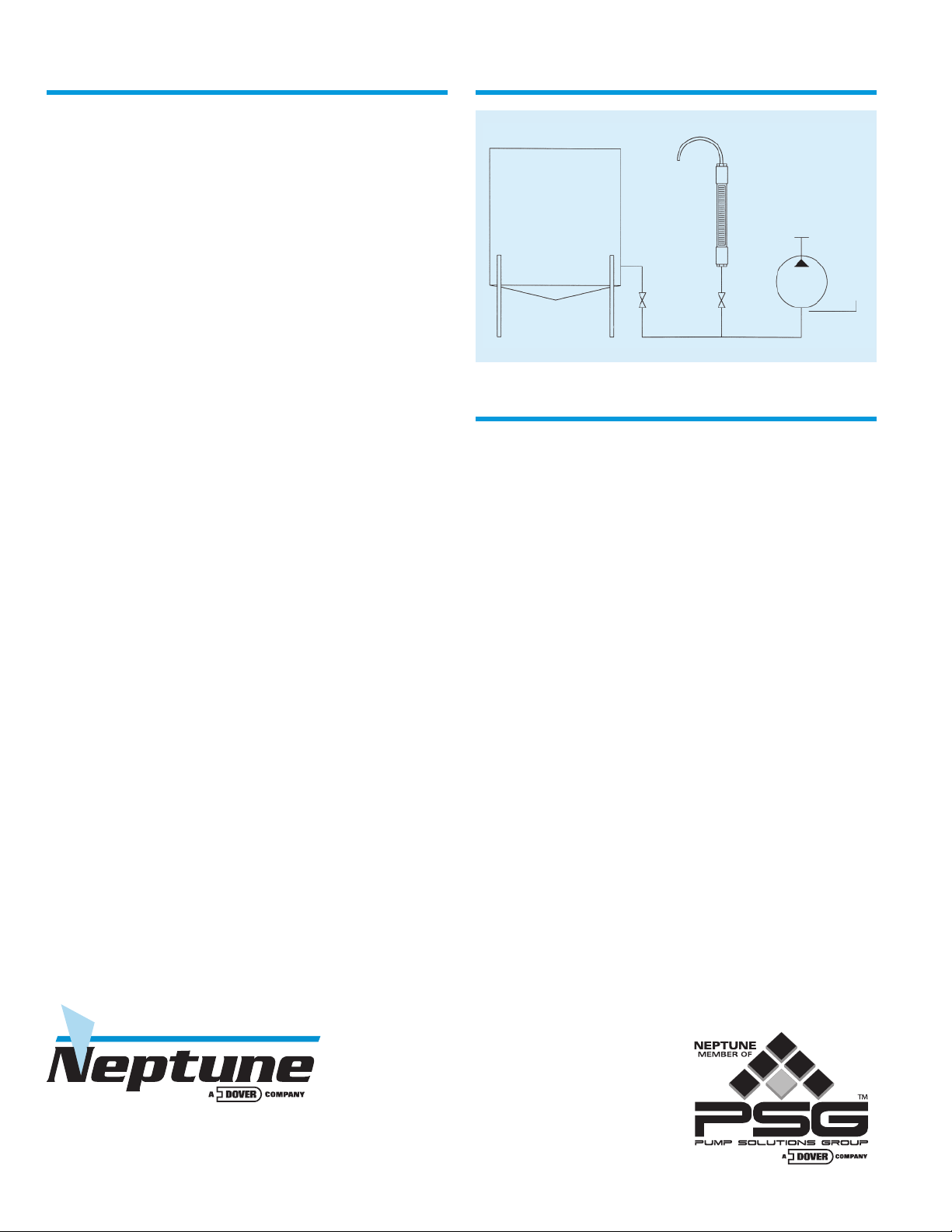
Installation Instructions
The recommended installation is shown below:
1. Install the Calibration Column in the suction line
of the Chemical Feed Pump. The column should be
installed in a vertical position.
2. Two (2) Ball Valves are required and must be
installed as shown in the adjacent drawing. Valves
are not included.
3. The column should be installed so it will be filled
regardless of the level of the tank. It is recommended
that the top connection of the column be connected
to a vent tube that is as high as the liquid level in the
tank to prevent accidental spillage in the event of a
valve malfunction or if the isolation valve is accidentally left open. Do not install any valve in this overflow
line, as the test tube must be vented to atmosphere
at all times.
CAUTION: Top cap is not glued to allow cleaning. Top
cap must be glued when vent is piped back to tank.
CAUTION: If the vent is not piped back to the tank
a “U” tube should be installed on the top of the column to prevent accidental splash-up for operator protection. Remember, the head in a tall tank can cause
the column to fill rapidly resulting in a squirt from the
small vent connection on the top of the column.
NOTE: When viewing the pump’s performance on a
calibration cylinder, each stroke of the pump should
steadily draw the liquid down to a dead stop and
then drawdown again. “Bouncing” in the column at
the end of the suction stroke is an indication of dirt
or clogging in the valves or possibly wear.
Recommended Installation
OVERFLOW PROTECTION LINE
RESERVOIR
CALIBRATION COLUMN
VALVE A
VALVE B
NEPTUNE
PUMP
UMP
P
UCTION
S
Operating Instructions
A stopwatch or wristwatch with sweep second hand
is required.
1. With the pump operating normally, Valve A is open
and Valve B is closed. Open Valve B slightly so the
column fills slowly with liquid.
2. When the liquid level reaches the zero division mark,
close Valve A (any division mark may be used as a
starting point, however, by filling to the zero mark,
you may measure over a longer period of time, enabling you to get a better calibration). Do not fill above
the zero division mark unless top cap is glued and
vent is piped to tank.
3. Allow liquid level to drop for a period of at least
30 seconds and note the mark on the column to
which the level has dropped. Re-open Valve A.
CAUTION—
IMPORTANT INSTALLATION NOTES:
a. This unit must be vented to atmosphere when in use.
b. Never use this device on discharge side of pump.
c. This device is intended for verification of metering
pump flow rate only.
d. Maximum Pressure = 25 psig
Maximum Temperature = 140°F
e. Not suitable for all chemicals. Consult Factory. Shielded
glass models available for acids and strong chemicals.
SOLD BY:
P.O. Box 247 • Lansdale, PA 19446-0247
Tel: 215-699-8700 • Fax: 215-699-0370
Toll-Free Tel: 1-888-3NEPTUNE (1-888-363-7886)
Toll-Free Fax: 1-800-255-4017
Web Site: http:// www.neptune1.com
E-mail: pump@neptune1.com
© 2008 Neptune Chemical Pump Company All Rights Reserved Bulletin CC-08 P/N ZL107028 Printed in U.S.A.
4. Each column has two scales. The left hand scale
shows the volume of the column in ml. Dividing the
volume pumped by the time to pump gives you the
flow rate. The right hand scale is direct reading in
gallons per hour for a 1 minute test. If the test time is
exactly 1 minute, the drop in the column indicates the
flow rate. Double the number on the right hand scale
for a 30 second test.
5. When the gauge is not in use, Valve B must be closed.
6. Valve A must remain open at all times except when
testing the pump rate.
 Loading...