

Page 1
OPERATING &
NSTRUCTION
I
M
NEPTUNE SERIES 7000
Mechanical “dia-PUMP”
Tel.: 215-699-8700 •FAX: 215-699-0370
ANUAL
MODEL 7000
CHEMICAL PUMP CO., INC.
204, Dekalb Pike,
Lansdale, PA 19446
ZL104440
Page 2

WARNING
LOCKOUTS ARE REQUIRED BEFORE
SERVICING THIS EQUIPMENT.
Shut off/Lockout pump Power before Servicing.
SAFETY INSTRUCTIONS:
Be certain pump isolation valves are
Closed and chemical is shut off.
Bleed pressure before servicing.
2
Page 3

SECTION PARAGRAPH PAGE
I
II
1
2
3
4
5
III NORMAL MAINTENANCE
6
PARTS LIST
IV 7 MOTOR OPERATING CONDITIONS 14
V TROUBLE SHOOTING CHART 14
DRAWINGS
GENERAL DESCRIPTION 4
LIMITED WARRANTY 5
PARTS ORDERING INSTRUCTIONS 6
INSTALLATION INSTRUCTIONS
GENERAL
SUCTION PIPING
DISCHARGE PIPING
INSTALLATION OUTDOORS
STARTUP PROCEDURE
MAINTENANCE
FOR 7000 SERIES PUMP
BALLOONED DRAWING 7000 PUMP
BASIC DIMENSION OF 7000 SERIES PUMP
TABLE OF CONTENTS
7
8
9
9
9
10
13
12
15
3
Page 4

SECTION I
GENERAL DESCRIPTION
The Neptune Series 7000 Mechanical Diaphragm metering pump is a reliable me tering pump of the Low-pressure
diaphragm type. Under constant conditions of temperature, pressure, and capacity adjustment settings, a +/- 2%
metered discharge volume is maintained. Rugged contoured composite diaphragm designed for high mete ring
accuracy over a full 10:1 turndown range.
A plunger reciprocating at a set fixed stroke, actuates a flexible, chemically inert, Teflon faced diaphragm, to create
pumping action. Screwing in and out a hand knob regulates the capacity of the pump. Screwing in (shortens the
stroke length) reduces the volume and screwing out increases it. A percentage of flow is read on the scale.
Precision-engineered liquid ends meters mild solutions, aggressive chemicals, high viscosity polymers (up to
5000cP) and slurries (hydrated lime slurries up to 4 lbs of /gallon of water, activated carbon slurries up to 1 lbs
/gallon of water)
Metering accuracy is maintained by the ball check valves at the suction and discharge of the pump. The use of screw
in cartridge ball check valves eases maintenance.
Temperature limitations on the plastic heads are 36 – 125°F (2 - 52°C)
Mechanical diaphragm pumps are positive displacement reciprocating pump s. Each pump consists of a power end
and a process end separated by mechanically operated Teflon faced diaphragm. Individual pumps will vary in
appearance due to various liquid ends; however, the basic principles of operation remain the same.
PLEASE READ THE INSTRUCTION MANUAL COMPLETELY BEFORE INSTALLING THE PUMP
4
Page 5

SECTION I
NEPTUNE CHEMICAL PUMP COMPANY
LIMITED WARRANTY
All Neptune Pumps are tested at the factory prior to shipment. Each part used in their construction has been carefully
checked for workmanship.
If the pump is installed properly, Neptune Chemical Pump Company, Inc. warrants to the purchaser of this product
for a period of twelve months from the date of first use or eighteen months from shipment, whichever occurs first, this
product shall be free of defects in material and/or workmanship, as follows:
1 Neptune Chemical Pump Company, Inc. will replace, at no charge, any part that fails due to a defect in
material and/or workmanship during the warranty period, FOB our factory, Lansdale, Pennsylvania. To obtain
warranty service, you must forward the defective parts to the factory for examination, freight pre-paid.
1 This warranty period does not cover any product or product part, which has been subject to accident,
misuse, abuse or negligence. Neptune Chemical Pump Company, Inc. shall only be liable under this
warranty if the product is used in the manner intended by the manufacturer as specified in the written
instructions furnished with this product.
Any express warranty not provided in this warranty document, and any remedy for breach of contract that, but for this
provision, might arise by implication or operation of law, is hereby excluded and disclaimed. Under no circumstances
shall Neptune Chemical Pump Company, Inc. be liable to purchaser or any other person for any charge for labor,
repairs, or parts, performed or furnished by others, nor for any incidental consequential damages, whether arising out
of breach of warranty, express or implied, a breach of contract or otherwise. Except to the extent prohibited by
applicable law, any implied warranty of merchantability and fitness for a particular purpose are expressly limited in
duration to the duration of this limited warranty.
Some states do not allow the exclusion or limitation of incidental or consequential damages, or allow limitations on
how long any implied warranty lasts, so the above limitations may not apply to you. This warranty gives you specific
legal rights, and you may have other rights, which may vary from state to state.
1
IMPORTANT
SHOULD IT BE NECESSARY TO SEND THE PUMP TO THE FACTORY FOR REPAIR OR MAINTENANCE
REBUILDING; DRAIN ALL OIL AND CHEMICAL FROM PUMP BEFORE SHIPPING. FAILURE TO DO SO CAN
CAUSE EXTENSIVE DAMAGE TO THE MOTOR.
SEE IMPORTANT NOTICE – RETURN GOODS AUTHORIZATION
1
IMPORTANT NOTICE
RETURN GOODS AUTHORIZATION
(1) All equipment returned to Neptune Chemical Pump Company, Inc. requires proper Returned
Goods Authorization Number (RGA) and tags.
(2) All equipment returned to the factory for repair or service must first be thoroughly flushed and have
all chemical contact areas neutralized.
(3) All equipment which has been in contact with chemicals must be accompanied by a copy of the
Chemical Product Material Safety Data Sheet (MSDS).
(4) Failure to comply with the above instructions will result in equipment being returned to sender,
freight collect, without service.
5
Page 6
SECTION I
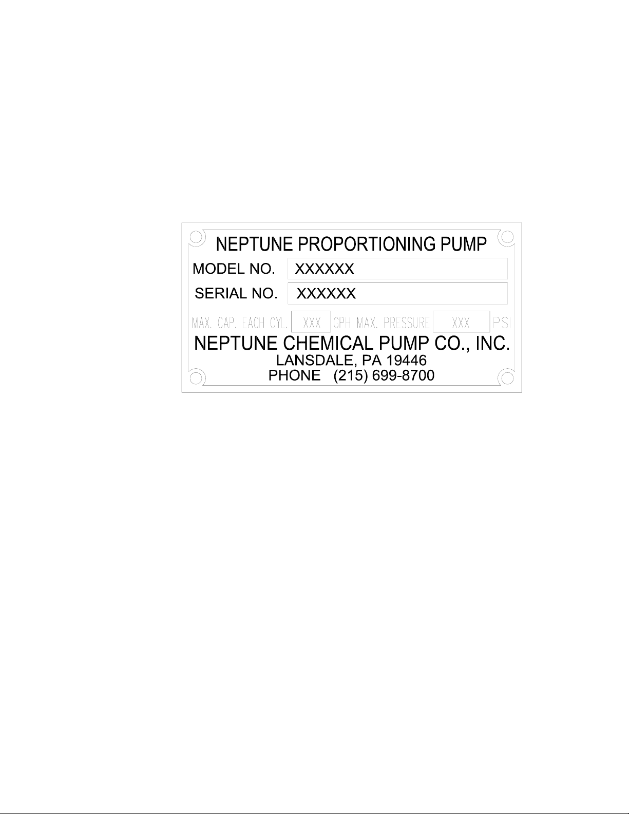
PARTS ORDERING INSTRUCTIONS
The complete model number and serial number of the pump must be furnished to insu re prompt and
accurate parts service. These numbers are found on the name plate (sample below) located on the side
of the pump.
Please refer to page number (13) for parts list. Ballooned drawing of the pumps can be found on pag es
(12) and (14).
Send all orders or inquiries for parts to:
Parts Department
Neptune Chemical Pump Company, Inc.
P.O. Box 247
Lansdale, PA 19446
Tel.: 215-699-8700
1 -888-3NEPTUNE (888-363-7886)
FAX: 215-699-0370
NOTE: PLEASE SUPPLY BOTH MODEL AND SERIAL NUMBERS.
6
Page 7

1.0 GENERAL
1.0.1 UNPACKING & INSPECTION
When unpacking a pump or chemical feed system, be certain that no parts are thrown away.
Examine the equipment for possible damage. If damage has occurred, file claim with the common
carrier within 24 hours. Neptune will assist in estimating the repair costs.
1.0.2 The Mechanical Diaphragm metering pumps should be located on a level surface. Three mounting
holes are provided to anchor the pump securely to the mounting surface. All piping to the pump
should be supported to prevent stress on the pump input and output fittings.
1.0.3 Before connecting the pump make sure that all fittings are completely clean by flushing thoroughly.
Foreign matters with sharp edges entering the pump can damage the diaphragm and severely limit
the life of the pump.
1.0.4 A “Y” STRAINER (AT LEAST ONE PIPE SIZE LARGER THAN SUCTION INLET SIZE OF THE
PUMP) MUST BE INSTALLED IN THE SUCTION LINE OF THE PUMP TO INSURE AGAINST
FOREIGN MATTER ENTERING THE PUMP
1.0.5 It is recommended that shut-off valves and unions be placed in the suction and discharge lines if
possible. Such an arrangement will facilitate servicing the pump.
1.0.6 The electrical supply to the pump must match the motor nameplate characteristics. The motor
rotation is counter clockwise when viewed from the top of the motor or looking down on the pump.
An arrow mark on the gearbox shows the rotation (See Figure 1)
On single-phase units, the rotation is set at the factory and must not be changed.
SECTION II
INSTALLATION INSTRUCTIONS
IMPORTANT
FIGURE 1
Please note Figure 1, indicating the correct rotation. Operation with the incorrect rotation will
damage the pump and motor.
1.0.7 Fill gearbox and pump by pouring the specified gear oil (drive lubricant) supplied through the
Breather (see note) at the rear of the pump. Pour fluid in slowly until it covers the worm gear.
PLEASE NOTE: Oil may be poured through breather. Snap off the breather top and remove the breather
sponge to fill oil and then reinstall sponge and breather top.
7
Page 8

The hydraulic fluid supplied by Neptune is:
EP Gear Oil, ISO #68, Norton Petroleum Corp., 290 Possum Park Road, Newark, DE 19711
(302) 731-8220 CAS No.64742-54-7, 64742-65-0 or 64741-8 8-4.
Common sources for hydraulic fluid are:
All piping systems should include:
1.1.1 A separate system relief valve to protect piping and process equipment, including the pump, from
*An external relief valve is required!!
1.1.2 Shutoff valves and unions (or flanges) on suction and discharge piping. This permits check valve
1.1.3 An inlet strainer, if the product is not slurry. Pump check valves are susceptible to dirt and other solid
1.1.4 Valve housings or other portions of the reagent head must not support piping weight, as the resulting
SUCTION PRESSURE REQUIREMENTS
2.0 SUCTION PIPING
2.0.1 The suction piping to the pump must be absolutely airtight for optimum operation any leakage in the
2.0.2 NEPTUNE RECOMMENDS THAT The Mechanical Diaphragm metering pumps BE OPERATED
Alternate Oils Manufacturer
Omala #68 Shell Oil
Mobil Gear #626 Mobil Oil
Sun EP #68 Sun Oil
Meropa #68 Texaco
excess process pressures.
inspection without draining long runs of piping. Shutoff valves should be of the same size as connecting pipe. Ball valves are preferred since they offer minimum flow restriction.
contaminants unless designed for that service, and any accumulation can cause malfunction. The
strainer should be located between the suction shutoff valve and the pump suction valve. It must be
sized to accommodate the flow rate and the anticipated level of contamination. A 100-mesh screen
size is recommended.
stresses can cause leaks. In piping assembly, use a sealing compound chemically compatible with
the process material.
Although Mechanical Diaphragm metering pumps have suction lift capability, a flooded suction is
preferable whenever possible. The pump should be located as clo se a s po ssible to the suction side
reservoir or other source.
The pump will self-prime with 10 ft (3 meters) of water suction lift (wetted valves, zero back pressure,
full stroke and speed, water like solutions). Once primed, the pump is capabl e of up to 10 feet (3
meters) of water suction lift.
All Mechanical Diaphragm metering pumps are designed for continuous service at the rated
discharge pressure. The discharge pressure must exceed suction pressure by at least 6 Psia (or
0.41 Bar). This can be achieved where necessary by the installation of a backpressure valve in the
discharge line.
suction line will reduce pumping capacity. Pipe should be one size larger than suction inlet size of
the pump. It is suggested that the suction piping be tested with low air pressure and a soap sol ution
to assure that no leaks exist. Limit the total length of the suction line to 5-8 feet for suction lift or 8-10
feet for flooded suction. Minimize bends, elbows, or other restrictions for better pumping efficiency.
WITH A FLOODED SUCTION, AS THIS WILL FACILITATE START UP AND INCREASE THE
SERVICE LIFE OF THE PUMP.
8
Page 9

2.0.3 It is recommended that all solution tanks be furnished with a low level cut off switch or low-level
alarm and cut off switch to prevent the pump from running dry. Although the pump can run dry for a
few minuets. OPERATION AGAINST A DRY SYSTEM FOR A PROLONGED PERIOD MAY CAUSE
DAMAGE TO THE PUMP DIAPHRAGM AND REDUCE THE OPERATING LIFE OF THE PUMP.
3.0 DISCHARGE PIPING
3.0.1 It is recommended that the Mechanical Diaphragm metering pump o perate against a suitable back
pressure to facilitate better operation of the check valves.
3.0.3 To protect the pump, it is recommended that an external relief valve as manufactured by Neptune
Chemical Pump Company, or equal, be placed in the discharge line of the pump to avoid over pressure.
3.0.4 Discharge piping should equal discharge port size.
NOTE: All parts must have a working pressure rating above the required set pressure.
3.0.5 Start and run the pump.
3.0.6 Adjust the required percentage of flow required.
Do not attempt to run the pump in excess of its nameplate rating.
4.0 INSTALLATION OUTDOORS
The Mechanical Diaphragm metering pump is a totally enclosed pump, which can be used o utdoors or
indoors. When installed outdoors, make sure that the pump is protected against extremes of nature as
follows:
4.0.1 Running of the pump when exposed to tropical sunshine with ambient temperature above 90°F
(32°C) would cause excessive oil and motor temperatures. The pump should be shaded and located
in such a way as to permit an ample degree of air circulation.
4.0.2 Under cold conditions, the pump should be insulated and a heater should be supplied in order to
maintain the hydraulic fluid at an ambient temperature above 36°F (2°C.)
5.0 START UP PROCEDURE
The following start up procedure is complete and does repeat instructions on filling the gearbox and pump.
5.0.1 Open suction and discharge valve. (See recommendation 1.0.5)
5.0.2 Set capacity indicator to zero by turning hand knob clockwise.
5.0.3 Adjust backpressure close to zero.
5.0.3 Start pump.
5.0.4 On initial start-ups: Check for proper motor rotation (Refer to Paragraph 1.0.6). Listen for any
abnormal motor or crank noises, and if present, refer to trouble shooting chart.
5.0.5 Adjust pump to required capacity by turning hand knob anticlockwise.
5.0.6 Adjust pressure to requirement.
CAUTION
9
Page 10

6.0 MAINTENANCE
Under normal conditions, the Mechanical Diaphragm metering pumps should not require any significant
amount of maintenance. It is advised that periodic visual observations be made of the oil level to make sure
that it is over the worm gear. The liquid end of the pump should also be inspected for leakage. These
observations should be made regularly.
The Gear oil should be drained and replaced when necessary, removing the drain plug at the side of the
pump. This change can be scheduled with the normal factory maintenance at seasonal periods.
6.1.0 OIL CHANGE
6.1.1 Disconnect the power source to the drive motor
6.1.2 Relieve all pressure from the piping system.
6.1.3 Drain the oil by removing the drain plug at the lower rear side of the gearbox.
6.1.4 Replace the drain plug.
6.1. 5 Remove breather on the gearbox cover. (Or snap off the breather top and remove sponge)
6.1.6 Fill with oil.
6.1.7 Replace breather. (Or snap on the breather top after replacin g sponge)
6.2.0 CHECK VALVE REMOVAL CLEANING AND REPLACEMENT.
Should the valves need cleaning, remove as follows:
6.2.1 Disconnect the power source to the drive motor.
6.2.2 Relieve all pressure from the piping system.
6.2.3 Close the inlet and outlet shutoff valves.
6.2.4 Loosen and remove the suction and discharge valve cartridges slowly to drain any
6.2.5 Clean valve cartridges with suitable solvent. Both valve cartridges are complete and
6.2.6 To replace reverse above procedures. Make sure that the port orientation is right.
SECTION III
NORMAL MAINTENANCE
The recommended oil change intervals are depende nt upon the operating environment and
level of pump usage.
trapped liquid.
integral units and should not be disassembled for cleaning. If the valves are found to be
worn and in need of replacement, an entire valve cartridge in either suction or discharge
should be ordered.
10
Page 11

6.3.0 LIQUID HEAD REMOVAL, INSPECTION, AND REINSTALLATION
CAUTION
If the diaphragm has failed, any process fluid would pass through the bleed hole located
behind the diaphragm. Handle any liquid with appropriate care.
Mechanical diaphragms should operate for approximately 2000 ho urs under normal operating
conditions; however, the accumulation of foreign material or debris and abnormal operating condition
or simply age can cause failure. Failure can also occur as a result of system over pressure. Periodic
diaphragm inspection and replacement are recommended.
6.3.1 Adjust the stroke setting to “0” percent and disconnect the power source to the drive
motor
6.3.2 Relieve all pressure from the piping system.
6.3.3 Take all precautions described under “Caution” to prevent environmental and personnel
exposure to hazardous materials.
6.3.4 Disconnect piping to the reagent head and drain any process liquid.
6.3.5 Place a pan underneath the pump head adaptor to catch any liquid leakage.
6.3.6 Remove all but two top reagent head bolt. Product will leak out between the pump head
adaptor and reagent head as the bolts are loosened.
6.3.7 Tilt the head and pour out any liquids retained by the check valves into a suitable
container, continuing to follow safety precautions as appropriate.
6.3.8 Remove the final bolt and rinse or clean the reagent head with an appropriate material.
6.3.9 Inspect the diaphragm and remove the diaphragm if necessary, by turning counterclockwise. The diaphragm must be replaced if it is cracked, separated, or obviously
damaged.
6.3.10 To install a diaphragm, first ensure that the critical sealing areas of diaphragm, reagent
head, and pump head are clean and free of debris. Then lubricate the elastomer side of
the diaphragm liberally, where it is in contact against the intermediate chamber wall and
backup plate, with a lubricant (silicone grease is preferred).
6.3.11 Thread the diaphragm (clockwise) fully onto the shaft.
6.3.12 Install the reagent head bolts and tighten in an alternating pattern to ensure an even
pressure on all bolts.
11
Page 12

MODEL 7000
(SHOWN WITH 316SS LIQUID HEAD)
12
Page 13

PARTS LIST
7000 MECHANICAL DIAPHRAGM PUMP
ITEM
NO.
1 Gear Box 1 004410
2 Worm Gear 18 SPM 1 004540
Worm Gear 37 SPM 1 004541
Worm Gear 72 SPM 1 004542
Worm Gear 117 SPM 1 004543
Worm Gear 144 SPM 1 004547
3 Thrust Collar 2 004419
4 Shaft Retainer 1 000289
5 1/4-20 x 1/2" Lg. Screws 3 100254
6 Shaft Retainer Gasket 2 106290
7 Retainer Cover 1 004415
8 #10-32 x 1/2” Lg. Screws 7 100358
9 Stroke Adjuster Disk 1 004414
10 Retaining Ring, External 1 106593
11* O-Ring 1 107600
12 Retaining Ring, Internal 1 106592
13* Oil Seal 1 106586
14 1/4-20 x 7/8" Lg. Screws 4 100197
15 Pump Head Adapter 1 004411
16 Spring 1 108023
17 Piston Rod 1 004412
18 Ball Bearing 1 100359
19 Gear Shaft 1 104444
20 Thrust Washers 1 100252
21 Back Cover Gasket 1 104443
22 #8-32 x 1/2” Lg. Screws 6 100578
23 Back Cover Plate 1 004420
24 #10-32 x 5/8” Lg. Screws 3 106106
DESCRIPTION
QTY.
PART
NO.
ITEM
NO.
25 Hand Knob 1 107652
26 Hand Knob Adapter 1 004418
27 Spring Pin 1 100305
28 Hand Knob Set Screw 1 105017
29 Control Stud 1 004417
30 Control Stud Holder 1 004416
31 Control Stud External O-Ring 1 100322
32 Control Stud Internal O-Ring 1 100417
33 Thumb Screw 1 107677
34* Diaphragm 1 108022
39 1/4” Lock Washers 3 100169
40 1/4-20 x 3/4” Lg. Screws 3 108140
41 Bearing Cup 1 100179
42 Bearing Cone 1 100180
43 Worm Spring Pin 1 100181
44 O-Ring 1 100244
45 Worm Shaft Cover 1 004422
46 Pump Mount Bracket 1 001415
47 Drain Plug 1 100332
48 Worm 18 SPM 1 003516
Worm 37 SPM 1 000170
Worm 72 SPM 1 000172
Worm 117 SPM 1 000169
Worm 144 SPM 1 002817
49 Fill/Vent Plug 1 000191
50 Capacity Indicating Scale 1 104441
51 Breather Vent 1 104447
52 Street Elbow 1 101757
DESCRIPTION
QTY.
PART
NO.
PARTS FOR 7000 PUMP HEADS
ITEM
NO.
35
Pipe Plug 1 101859 ------ ------
36* Check Valve 2 003321 003279 003332
37 Liquid Head 1 003276 004578 004579
38 Pump Head Screws 8 101174 107766 107766
Washers 8 ------ 106857 106857
DESCRIPTION
QTY.
N3
PART NO.
N5
PART NO.
PART NO
Note: PARTS MARKED WITH “*” ARE Recommended SPARE PARTS
N8
13
Page 14

SECTION IV
r
MOTOR OPERATING CONDITIONS
7.0 The normal temperature rise for standard motors is 40°C above ambient temperature and, thus, it might
appear that the motor is operating at a higher than normal temperature. This situation is normal.
As a precaution against motor overheating, it is recommended that the pump be located where adequate
ventilation is available, It is also recommended that a MOTOR STARTER WITH THE PROPER OVERLOAD
PROTECTION BE SUPPLIED AS AN ADDITIONAL SAFETY DEVICE.
SECTION V
TROUBLE SHOOTING CHART
SYMPTOMS CAUSES REMEDIES
. Pump Motor Will Not
Operate.
Open thermal overload device in starter. Reset.
Low liquid level in tank (where low level
D. Broken wire. Locate and repair.
E. Low voltage. Check for too light wiring.
Oil “frozen” in pump. Thaw out.
Pump Does Not Deliver
Rated Capacity
B. Leaky suction piping. Pressure test, repair or replace defective piping.
C. Excessive suction lift. Rearrange equipment location to reduce suction lift.
Liquid too close to boiling point. Lower temperature or increase suction pressure slightly.
A. Blown Fuse. Check for short circuit or overload
Fill tank.
cut-off is used).
A. Starved suction.
Look for blockage in suction line.
Replace suction piping with larger size.
Worn or dirty valves or seats, or both. Clean or replace.
Viscosity of liquid too high. Reduce viscosity by heating or other means.
2. Increase size of suction piping
3. Increase suction pressure slightly
Low discharge pressure. A minimum discharge pressure of 25 psi is required to insure proper
capacity control
ump delivers erratically. Leaky suction line. Repair or replace piping.
Worn or dirty valves or seats, or both. Clean or replace valve assembly.
Excessive excursion of ball valves from
seats (indicated by ball chatter).
Insufficient suction pressure Increase suction pressure.
Raise tank level.
Liquid too close to boiling point, Reduce temperature or raise suction pressure.
Leaky system relief valve. Repair or replace relief valve
Motor overheats
thermal overload
activates,
Overload caused by operating pump
5. Noisy Operation
1. In Pump Pump Valves. Valves must move to open and close, and they will make a clicking noise
2. In Gear Reduce
Oil level Low Flexible diaphragm punctured Replace diaphragm
Gearbox hot
Power supply does not match motor. Check power supply against motor nameplate data.
beyond rated capacity
Pounding noise at high discharge pressure Fluid compressibility causes reversal of load on gears at end of pressure
Gearbox temp. may rise to 150°F. and may
be caused by various reasons and should
not raise any concern.
Increase backpressure.
Check operating pressure against pump manufacturer data plate
maximum rating
as they operate. These noises are sometimes amplified by natural
resonances in piping system. They are usually indications of normal
valve functioning.
stroke, Not considered detrimental.
In case of excessive heat buildup, contact factory.
14
Page 15

7000 Dimensions with Metal Head
7000 Dimensions with Plastic Head
15
Page 16

MATERIAL SAFETY DATA SHEET Page 1 of 4
1. CHEMICAL PRODUCT AND COMPANY IDENTIFICATION
Product Name: EP 68 Gear Oil
Product Code:
Generic Name: Heavy-duty, Multi-grade Gear Oil
Chemical Family: Petroleum Hydrocarbons & Additives
Manufacturer: Scot Lubricants Emergency Telephone Numbers
1801 E. Tremont Street Information: 610-433-2527 8am-5pm - EST M-F
P.O. Box 326 C H EMTREC: 800-424-9300 24 hrs – every day
Allentown, PA 18105
2. CAUTION Summary of Hazards
May cause mild eye irritation and/or mild skin irritation and inflammation. Avoid eye contact and
prolonged and/or repeated skin contact.
HAZARD RATING
TOXICITY – 1 0=INSIGNIFICANT 1=SLIGHT
FLAMMABILITY – 1 2=MODERATE 3=HIGH
REACTIVITY – 1 4=EXTREME
3. Fire Fighting Measures
Flash Point (Method) Autoignition Temperature (Method) Flammable Limits in Vol
4. FIRST AID MEASURES
INHALATION: Move to fresh air
EYE CONTACT: Flush with water for at least 15 minutes. If irritation persists, obtain medical assistance.
SKIN CONTACT: Wash with soap and water until no odor remains. If redness or swelling develops, obtain
medical assistance. Wash clothing before reuse.
INGESTION; Practically non-toxic. Induction of vomiting not required. Obtain emergency medical attention.
Small amounts, which accidentally enter mouth, should be rinsed out until taste of it is gone.
5. FIRE FIGHTING MEASURES
FLASHPOINT (METHOD): 390°F Minimum COC; 201°C Minimum COC
FLAMMABLE LIMITS: Not established.
AUTO-IGNITION TEMP: 675°F Estimated; 359°C Estimated
EXTINGUISHING MEDIA: Water spray, dry chemical, carbon dioxide (CO2), foam.
FIRE FIGHTING INSTRUCTIONS: Avoid breathing smoke and vapor.
FIRE FIGHTING EQUIPMENT: Wear self-contained breathing apparatus and protective clothing. Use water
spray to keep fire-exposed containers cool.
HAZARDOUS COMBUSTION PRODUCTS: Normal combustion forms carbon dioxide and water vapor;
incomplete combustion can produce carbon monoxide.
Revision: 05/05/2007 NA= Not Applicable ND=No Data NE=Not Established
16
Page 17

EP 68 Gear Oil Page 2 of 4
6. ACCIDENTAL RELEASE MEASURES
SPILLS OR LEAKS: Contain spills, advise EPA, state agency, if required. Absorb on inert material, shovel,
sweep, or vacuum spill.
7. HANDLING AND STORAGE
NFPA Class IIIB Storage. Wash thoroughly after handling.
8. EXPOSURE CONTROLS/PERSONAL PROTECTION
VENTILATION: Ventilate as needed to comply with exposure limit. General Dilution ventilation acceptable.
PERSONAL PROTECTIVE EQUIPMENT –
EYE: Splash proof chemical goggles recommended to protect against splash of product.
GLOVES: Protective gloves recommended when prolonged skin contact cannot be avoided. The following glove
materials are acceptable: polyvinyl chloride (PVC); neoprene; nitrile; polyvinyl alcohol; viton.
RESPIRATOR:
Respiratory protection usually not needed unless product is heated or misted. Half-mask air purifying respirator with dust/mist
filters or HEPA filter cartridges is acceptable to 10 times the exposure limit. Full-face air purifying respirator with dust/mist
filters of HEPA filter cartridges is acceptable to 50 times the exposure limit. Protection by air purifying respirators is limited.
Use a positive pressure demand full-face supplied air respirator or SCBA for exposures above 50X the exposure limit. If
exposure is above IDLH (immediately dangerous to life and health) or there is the possibility of an uncontrolled release or
exposure levels are unknown, then use a positive pressure demand full-face supplied air respirator with escape bottle or SCBA.
Concentration in air determines protection needed. Use only NIOSH certified respiratory protection.
OTHER: If contact is unavoidable, wear chemical resistant clothing. The following materials are
acceptable as protective clothing materials: polyvinyl alcohol (PVA); polyvinyl chloride (PVC); neoprene;
nitrile; viton; polyurethane. Launder soiled clothes.9. PHYSICAL AND CHEMICAL PROPERTIES
9. PHYSICAL AND CHEMICAL PROPERTIES
APPEARANCE/ODOR: AMBER FLUID/SLIGHT ODOR .BOILING POINT: HIGH
VAPOR PRESSURE <0.0001 (MM HG @ 20°C) MELTING POINT: N/A
MOLECULAR WEIGHT: N/A (G/MOLE) PACKING DENSITY: N/A
SOLUBILITY IN WATER: NIL (% BY VOLUME) OCTANOL/WATER COEFF: N.D.
EVAPORATION RATE: 1000X SLOWER (ETHYL ETHER=1) ODOR THRESHOLD: N.D.
SPECIFIC GRAVITY: 0.86 (WATER=1) VAPOR DENSITY: 10+ (AIR=1)
VISCOSITY: 55 SUS @ 210°F 68 CST @ 40°C
10. STABILITY AND REACTIVITY
STABILITY: Stable
CONDITIONS TO AVOID: None known.
MATERIALS TO AVOID: Strong oxidizing agents.
HAZARDOUS POLYMERIZATION: Will not occur.
HAZARDOUS DECOMPOSITION: Combustion will produce carbon monoxide and asphyxiants
.
11. TOXICOLOGICAL INFORMATION
FOR THE PRODUCT –
INHALATION: Low acute toxicity. SKIN: Practically non-toxic if absorbed. Mild irritation with prolonged or
repeated contact. EYE: Mildly irritating on contact. ORAL: Practically non-toxic. Acute toxicity: estimated oral
LD50 in rats is: >15 g/kg. Estimated draize skin irritation score is: 2.10 out of 8.0
Revision: 05/05/2007 NA= Not Applicable ND=No Data NE=Not .Established
17
Page 18

EP 68 Gear Oil Page 3 of 4
11. TOXICOLOGICAL INFORMATION – cont’d
SEVERELY SOLVENT REFINED HEAVY PARAFFINIC PETROLEUM OIL: INHALATION: Low acute
toxicity. SKIN: Practically non-toxic if absorbed; may cause moderate irritation with prolonged and repeated
contact. EYE: Minimally irritating on contact. INGESTION: Practically non-toxic if swallowed.
CALCIUM SULFONATE: INHALATION/INGESTION: No data available. SKIN: Moderate irritant.
Cause allergic skin reaction in animals. EYE: Moderate to severe irritation.
BUTYLATED PHENOL: No data available for all routes of exposure.
ZINC DIALKYL DITHIOPHOSPHATE: INHALATION: Toxic hydrogen sulfide is generated when heated
above 155 deg. F. This can cause respiratory collapse, coma, or death. SKIN: Prolonged or repeated contact may
cause moderate irritation, redness, drying, cracking, and dermatitis. EYE: Irritant. ORAL: Harmful if swallowed.
ACRYLIC COPOLYMER: No data available for all routes of exposure.
2-ETHYLHEXANOL: INHALATION: Overexposure may cause nose/throat irritation, nasal discomfort and
discharge, chest pain, cough, headache, nausea, vomiting. SKIN: Irritant. Prolonged/repeated contact may cause
redness and swelling. Prolonged widespread absorption caused CNS (Brain) depression, stupor, and unconsciousness in animals. EYE: Severe irritant. May cause corneal injury. ORAL: Moderately toxic. May cause abdominal
discomfort, nausea, vomiting, diarrhea, unconsciousness, and other CNS (Brain) effects. Liver and kidney injury
(repeated ingestion). PREGNANT RATS: Skin contact up to 3 ml/kg. Maternal toxicity, but no birth defects; oral
dose 2 ml/kg. Embryo/fetal toxicity and possibly increased birth defects.
TOLUENE: INHALATION: Vapor harmful. Overexposure to high concentration will cause eye, nose, and throat
irritation. CNS (Brain) effects, dizziness, breathing difficulties, coma, and death. Reports of heart beat irregularities
from massive exposure. Prolonged overexposure can cause brain, liver, kidney effects and/or damage. ORAL:
Harmful or fatal if swallowed. PULMONARY ASPIRATION HAZARD: Can enter lungs and cause damage.
PREGNANT: May cause mental and/or growth retardation in children of female solvent abusers. Prolonged
breathing in rats was toxic to fetuses and mothers – 15000 ppm. No birth defects-5000 ppm. No effects 750 ppm.
12. ECOLOGICAL INFORMATION
ECOTOXICITY: No data available.
13. DISPOSAL INFORMATION
Follow federal, state, and local regulations. Not RCRA hazardous waste if uncontaminated. If “used”, RCRA
criteria (ignitability, reactivity, corrosivity, toxicity characteristics) must be determined. Do not flush to drain/storm
sewer. Contract to authorized disposal service.
14. TRANSPORTATION INFORMATION
DOT
PROPER SHIPPING NAME Petroleum Lubricating Oil
HAZARD CLASS Not regulated
ID NUMBER Not regulated
LABEL REQUIRED Not regulated
IMDG PROPER SHIPPING NAME N.D.
IATA PROPER SHIPPING NAME N.D.
Revision: 05/05/2007 NA= Not Applicable ND=No Data NE=Not Established
18
Page 19

EP 68 Gear Oil Page 4 of 4
15. REGULATORY INFORMATION
TSCA: This material complies with the TOXIC SUBSTANCES CONTROL ACT (15 USC 2601-2629) and is listed
in the TSCA Inventory.
SARA 302 THRESHOLD PLANNING QUANTITY N/A
SARA 304 REPORTABLE QUANTITY N/A
SARA 311/312 REPORTING Health Immediate (acute) No
Health Delayed (Chronic) No
Physical Fire No
Physical Sudden Release of Pressure No
Physical Reactive No
When a product and/or component is listed below, the regulatory list on which it appears is indicated.
ZINC DIALKYL DITHIOPHOSPHATE – NJ 01
TOLUENE – CA FL MA MN NJ PA 01 07
2-ETHYLHEXANOL – MA PA
01=SARA 313 02-SARA 302/304 03=IARC CARCINOGEN
04-OSHA CARCINOGEN 05=ACGIH CARCINOGEN 06=NTP CARCINOGEN
07=CERCLA 302.4 08=WHMIS CONTROLLED PROD.
10-OTHER CARCINOGEN
PA=PA RTK NJ=NEW JERSEY RTK CA=CALIFORNIA PR OP 65
MA=MASS. RTK MI=MICHIGAN 406 MN=MINNESOTA RTK
FL=FLORIDA RI=RHODE ISLAND IL=ILLINOIS
NY=NEW YORK WV=WEST VIRGINIA CT=CONNECTICUT
LA=LOUISIANA ME=MAINE OH=OHIO
16. OTHER INFORMATION
SCOT LUBRICANTS OF PA, INC.
1801 E. TREMONT STREET
P.O. BOX 326
ALLENTOWN, PA 18105
610-433-2527
The information on this form is furnished solely for the purpose of compliance with the OSHA Act, and shall not be
used for any other purpose. The information herein is given in good faith and is based on data considered accurate.
However, no warranty, expressed or implied, is made regarding the accuracy of these data or the result to be obtained
from the use thereof.
Revision: 05/05/2007 NA=Not Applicable ND=No Data NE=Not Established
19
Page 20

MAINTENANCE LOG
Pump Model___________________________
Strokes Per Minute______________________
Piston Diameter________________________
Spare Parts Kit #____________________________________________________________
NEPTUNE CHEMICAL PUMP CO., INC. Tel.: 215-699-8700 • FAX: 215-699-0370
DATE SERVICED BY MAINTENANCE PERFORMED
Serial #_______________________________
Maximum Flow________________________
Maximum Pressure_____________________
20
 Loading...