

Your Pump House Condensate Pump is designed as an automatic condensate
removal
pump for pumping away room temperature condensate water dripping
from
air conditioner/refrigeration evaporative coils. The pump is controlled by a
float/switch
mechanism which turns the pump on to discharge the water when
approximately
55mm depth of water collects in a tank. The pump automatically
switches
off when the tank drains to approximately 30mm deep.
The
Pump House Condensate Pump you have purchased is a high quality
product
that has been engineered to give you long and reliable service.
This
pump is carefully packaged, inspected and tested to ensure safe operation
and
delivery. When you receive the pump, examine it carefully to determine
there
are no broken or damaged parts that may have occurred during
shipment.
If damage has occurred, please contact your supplier. They will
assist
you in replacement or repair, if required.
READ
INSTRUCTIONS CAREFULLY BEFORE ATTEMPTING TO INSTALL,
OPER
ATE OR SERVICE THE PH-2L PUMP. KNOW THE PUMP APPLICATION,
LIMITATIONS AND POTENTIAL HAZARDS. PROTECT YOURSELF AND OTHERS
BY OBSERVING ALL SAFETY INFORMATION. FAILURE TO COMPLY WITH
INSTRUCTIONS COULD RESULT IN PERSONAL INJURY AND/OR PROPERTY
DAMAGE! RETAIN INSTRUCTIONS FOR FUTURE REFERENCE. INSTALLATION
AND
CONNECTIONS ARE TO BE MADE BY A QUALIFIED PERSON.
SAFETY GUIDELINES
DO NOT USE TO PUMP FLAMMABLE OR EXPLOSIVE FLUIDS SUCH AS
PETRO
L, FUEL OIL, KEROSENE, ETC. DO NOT USE IN EXPLOSIVE
ATMOSPHERES. PUMP SHOULD BE USED WITH LIQUIDS COMPATIBLE
WITH
PUMP COMPONENT MATERIALS.
DO
NOT HANDLE PUMP WITH WET HANDS OR WHEN STANDING ON WET
OR
DAMP SURFACE, OR IN WATER. THIS PUMP IS SUPPLIED WITH AN
EARTHING
CONDUCTOR AND/OR EARTHING TYPE ATTACHMENT PLUG. TO
REDUCE
THE RISK OF ELECTRICAL SHOCK, BE CERTAIN THAT IT IS
CONNECTED
TO A PERMANENT EARTH.
FOR
INSTALLATIONS WHERE PROPERTY DAMAGE AND/OR PERSONAL
INJURY
MIGHT RESULT FROM AN INOPERATIVE OR LEAKING PUMP DUE TO
POWER
CUTS, DISCHARGE LINE BLOCKAGE, OR ANY OTHER REASON, A
BAC
KUP SYSTEM(S) AND/OR ALARM SHOULD BE USED.
SUPPORT THE PUMP AND PIPING WHEN ASSEMBLING AND WHEN
INS
TALLED. FAILURE TO DO SO MAY CAUSE PIPING TO BREAK, PUMP TO
FAIL, MOTOR BEARING FAILURES, ETC.
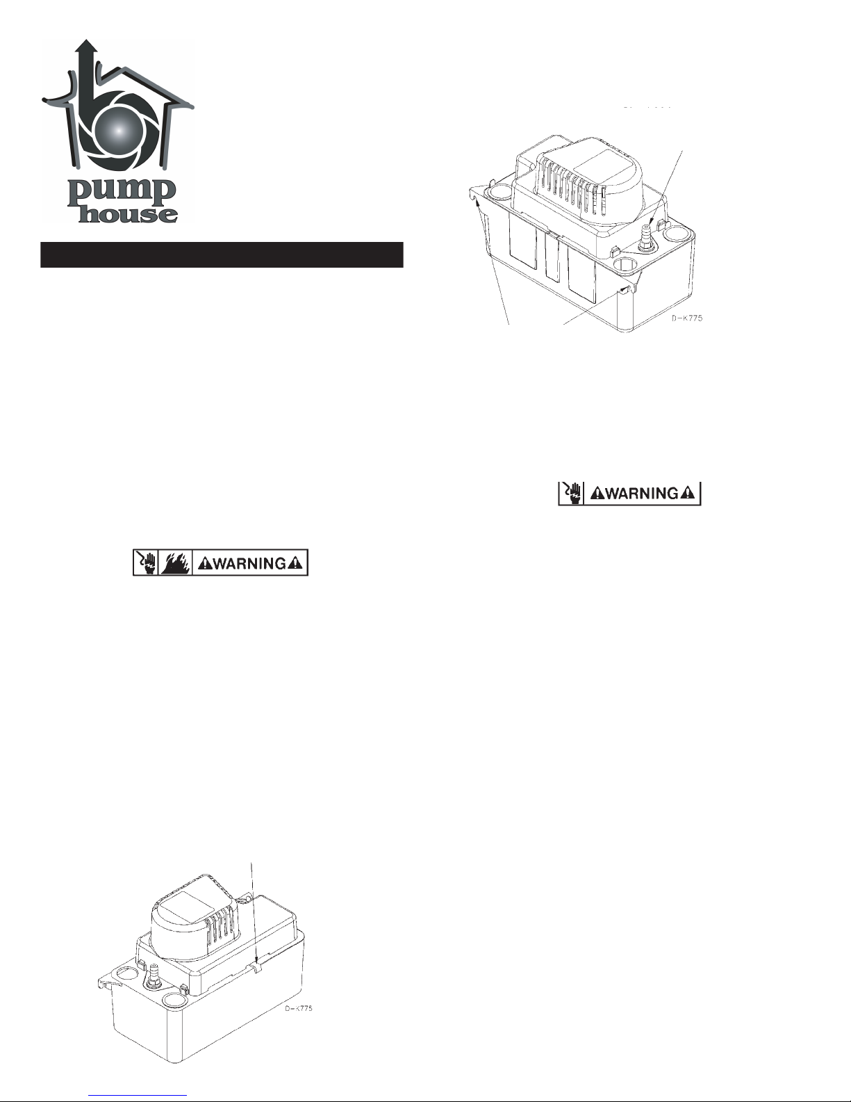
INSTALLATION
1. Carefully unpack the pump. Remove the cardboard packing from the motor
cover
air slots. Carefully slide the packing away from the pump. This
packing
is used to prevent switch movement during shipment (Fig. 1).
INTRODUCTION
2. Mounting the pump: The tank has two slots provided to mount the unit
on a vertical surface such as an adjacent wall. The slots are located on
the
ends of the tank (Fig. 2). Pump must be level and the inlet must be
below the coil drain. Conduit fittings are not compatible with the plastic
pump housing.
3.
The pump should not be installed in a manner that will subject it to
splashing
or spraying.
4.
This pump is not intended for use inside air plenums.
ELECTRICAL CONNECTIONS
1. Shut off electrical power at fuse box before making any connections. All wiring
must
comply with local codes.
2. Line
voltage: Connect pump to voltage specified on label located on
pump.
Wiring is as follows:
Live
(Line) - Brown
Neutral
- Blue
Earth
- Yellow/Green
3. If fused plug is used, a 1.0 amp fuse is recommended.
WATER DRAIN CONNECTIONS
Inlet Water Connections
1.
Position pump beneath a/c or refrigeration condensate drain so that
condensate
water flows into pump inlet freely (use any of the three
openings
provided).
2.
The pump will accept up to three drain lines, although care should be
used
to make certain that total inflow does not exceed outflow of pump.
If
more water drains into the pump than the rated output of the pump,
tank
may overflow.
3.
Keep plugs in unused pump inlet openings to prevent debris from falling
into
the pump tank.
Outlet
Water Connections
1.
Connect 3/8" I.D. tubing to the discharge adapter (item 5, figure 4). For best
results, secure tubing with clamps (not provided) but do not pinch collapse
or
otherwise restrict the tubing.
2.
Tubing should rise vertically but not exceed the maximum shut off head
(pumping
height) of 4.8 metres above the pump.
3.
At highest point angle tubing horizontally and create a downward slope
to
drainage point. Do not sharply bend or twist the tubing in a way that
might
result in collapse or restriction of the tubing. Creating a
downward
slope will allow water to drain by gravity and keep tubing
empty
of water.
4. If it is not possible to create a downward slope, try to create an inverted “U”
trap
directly above the pump at the highest point.
1
CONDENSATE
REMOVAL PUMP
PH-2L
Figure 1.
Figure 2.
Remove cardboard insert.
Check Valve
Mounting Slots
COMMISSIONING & MAINTENANCE
1. Before servicing the pump, disconnect the electric power at the fuse box.
2. Upon commissioning, check for debris in the drain pan. Remove any
material that might block the drain line or drain into the pump tank.
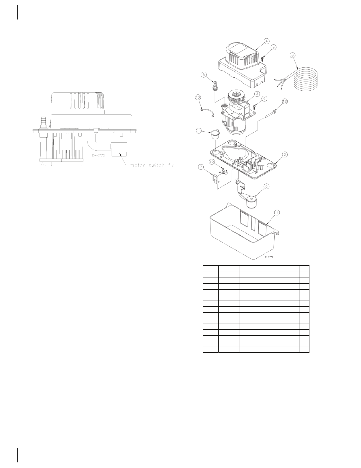
3. It is recommended that the pump be checked every six months for proper
operation. Most important is to check for debris blocking the pump
discharge adapter/check valve. Check for proper free movement of pump
float (Figure 3) and switch and check for free, unrestricted movement of
motor and fan.
4. Clean the holding tank and float with warm water and mild soap. Rinse
completely when finished.
5. Check the inlet and outlet piping. Clean as necessary. Be sure there are no
kinks in the outlet line that would inhibit or restrict flow.
TESTING
1. Turn on power.
2. Remove motor/tank cover assembly and hold level.
3. Test motor switch by raising motor switch float with finger (Figure 3). Motor
should turn on just before float contacts underneath side o f cover.
4. Replace motor/tank cover assembly on tank.
2
Figure 3.
ITEM P/N Description QTY
1 14940690 Tank 1
2 154411
Tank, Cover 1
3 154493 Motor,Plate,Volute , Assy 1
4 14940097 Cover, Motor 1
5 154715 Check Valve 1
6 154452 Float Arm 1
7 154471 Sw itch Holder 1
8 951089 Wiring Harness A
ssy ,
230V, 6FT. 1
9 902414 Tapping Screw 5
10 950337 Sw itch 1
11 929602 Drain Hole Plug 2
12 154455 Float Pivot Pin 1
13 951941 Lead Wire Assy 1
14 154037 1/4" ID Tubing Adaptor (Not Shown) 1
Motor Switch Float
Form 998389 — 09/2006
Figure 4.
 Loading...