

Pump House PH-20-STA Installation, Operating And Maintenance Instructions

Installation, Operating and
Maintenance Instructions
Boiler Condensate Pump - PH-20-STA
1. INTRODUCTION
1.1 Your Condensate Pump is designed as an automatic condensate removal pump for pumping away room temperature
condensate water dripping from condensing boilers. The pump is controlled by a float/switch mechanism which turns
the pump on to discharge the water when approximately 30mm of water collects in a tank. The pump switches off
automatically when the tank drains to approximately 9mm.
1.2 The condensate pump you have purchased is a high quality product that has been engineered to give you a long and
trouble-free service.
1.3 This pump is carefully packaged, inspected and tested to ensure safe operation and delivery. When you receive the
pump, examine it carefully to determine there are no broken or damaged parts that may have occured during shipment.
If damage has occured, please contact your supplier. They will assist you in replacement or repair, if required.
1.4 Read instructions carefully before attempting to install, operate or service the pump. Know the pump application,
limitations and potential hazards. Protect yourself and others by observing all safety information. Failure to comply
with instructions could result in personal injury and/or property damage! Retain instructions for future reference.
Installation and connections are to be made by a qualified person.
2. SAFETY GUIDELINES
2.1 Do not use to pump flammable or explosive fluids such as petrol, fuel oil, kerosene, etc. Do not use in explosive
atmospheres. This pump should be used with liquids compatible with pump component materials.
2.2 Do not handle the pump with wet hands or when standing on wet or damp surface, or in water. To reduce the risk of
electrical shock, be certain that the electrical supply is connected to a permanent EARTH.
2.3 For installations where property damaged and/or personal injury might result from an inoperative or leaking pump due to
power cuts, discharge line blockage, or any other reason, a backup system(s) and/or alarm should be used.
2.4 Support the pump and piping when assembling and when installed. Failure to do so may cause piping to break, pump
to fail, motor bearing failures, etc.
2.5 The pump is designed to take boiler condensate and water up to 90˚C. Boiler pressure relief can be over 100˚C in these
conditions we recommend using the PH-3-8L-HW.
3. INSTALLATION
3.1 Mounting the pump: The tank has two slots provided to mount the unit on a vertical surface such as an adjacent wall.
The slots are located on the ends of the tank. The pump must be level.
3.2 The top of the pump can be fitted in either a right hand or left hand orientation, see the following photo’s, this is to enable
flexibility of electrical wiring, condensate pipework and hose connections.
3.3 The pump should not be installed in a manner that will subject it to splashing or spraying.
3.4 The following installation pipe routing options are available: (please see reverse)
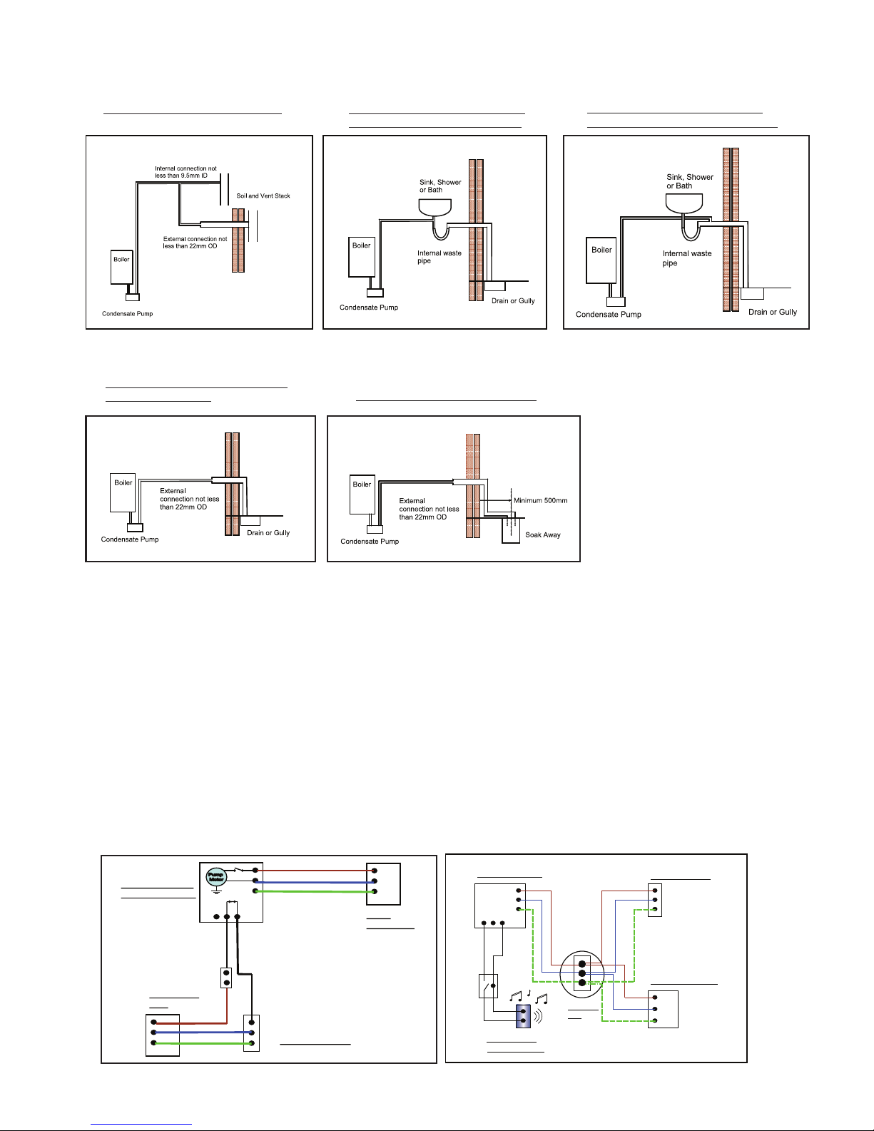
Connection to Soil and Vent stack Connection to internal waste pipe
upstream of sink, shower or bath
Connection to internal waste pipe
Connection to external drain, gully
down stream of sink, shower or bath
or rain water hopper
Connection to external Soak Away
4. ELECTRICAL CONNECTIONS
4.1 Shut off electrical power at fuse box before making any connections. All wiring must comply with local codes.
4.2 Line voltage: Connect the pump to voltage specified on label located on the pump:
Live (Line) - Brown
Neutral - Blue
Earth - Yellow/Green
4.3 If fused plug is used, a 3 Amp fuse is recommended.
4.4 Connection of the high level safety switch / potential free contact to either the boiler 240v circuit or an audible alarm.
The pump is fitted with a 240v micro switch which will activate if the pump starts to overfill in the event of outlet pipe
blockage or pump failure. The following wiring diagrams show how the switch can be connected into a boiler circuit
or a seperate audible alarm.
Boiler connection to the high level safety switch Audible alarm connection to the high level safety switch
N
L
E
Fused
Spur/Socket
L
N
E
NO
COM
NC
1
2
3
Boiler Condensate
Pump Connections
Permanent Live
N
E
Boiler Connection
(If less than 3A)
BR
BL
G/Y
Bk
Bk
BR
BL
G/Y
Boiler Fused
Spur
High level float
connection
N
L
E
L
N
L
L
N N
E
EE
NO NC COM
3
2
1
3
2
1
1
22
1
33
Condensate Pump
Boiler Connector
Fused Spur/Socket
BR
BL
G/Y
Bk Bk
Junction
Box
Audible Alarm
Or Visual Alarm
L
N
L
N
E
E
NO NC COM
3
2
1
 Loading...