

Service instruction
K 101, K 151, K 200, K 250, K 300
(M50 Motors)
K 101/151/200/250/300.58.0404.Eng/Digital

2 (15)
K 101/151/200/250/300.58.0404.Eng/Digital
SERVICE INSTRUCTION
K 101, 151, 200, 250, 300
Table of Contents
Introduction.............................................................................................................................3
Cross-sectional drawing........................................................................................................4
Nameplate..................................................................................................................4
Safety Precautions................................................................................................................4
Minimizing Environmental Impact..........................................................................................5
General Maintenance.............................................................................................................5
Disassembling
Removal from the Wet Well....................................................................................................6
Disassembling the Volute.....................................................................................................6
Adding and Changing the Oil..................................................................................................6
Changing the Cooling Liquid..................................................................................................7
Inspection of Terminal Board Area.........................................................................................7
Disassembling the Terminal Housing....................................................................................8
Disassembling the Cooling Jacket.........................................................................................8
Disassembling the Impeller....................................................................................................8
Disassembling the Seal Cartridge..........................................................................................8
Changing the Stator Unit........................................................................................................8
Disassembling the Stator.......................................................................................................9
Disassembling the Rotor and Bearings...............................................................................10
Assembling
Mounting...............................................................................................................................10
Mounting the Bearings.........................................................................................................10
Mounting the Rotor in the Oil Housing.................................................................................11
Mounting the Stator...........................................................................................................11
Mounting the Seal Cartridge.................................................................................................11
Mounting the Impeller.........................................................................................................12
Mounting the Cooling Jacket................................................................................................12
Mounting the Cable Seal......................................................................................................12
Mounting the Terminal Housing............................................................................................12
Mounting the Cover..............................................................................................................12
Mounting the Motor Unit to the Volute..................................................................................13
Adjusting the Wear Ring.......................................................................................................13
Testing.............................................................................................................................13
Recycling in Case of Scrapping the Pumps........................................................................13
Wiring Diagram.....................................................................................................................14
Torque Rating........................................................................................................................15
3 (15)
K 101/151/200/250/300.58.0404.Eng/Digital
SERVICE INSTRUCTION
K 101, 151, 200, 250, 300
This service manual covers pumps K 101, K 151, K 200, K 250 and K 300 with M50 motors in
the following designs:
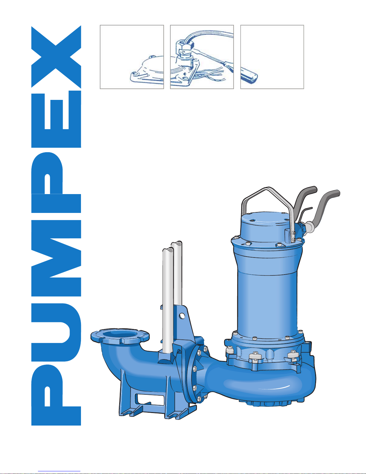
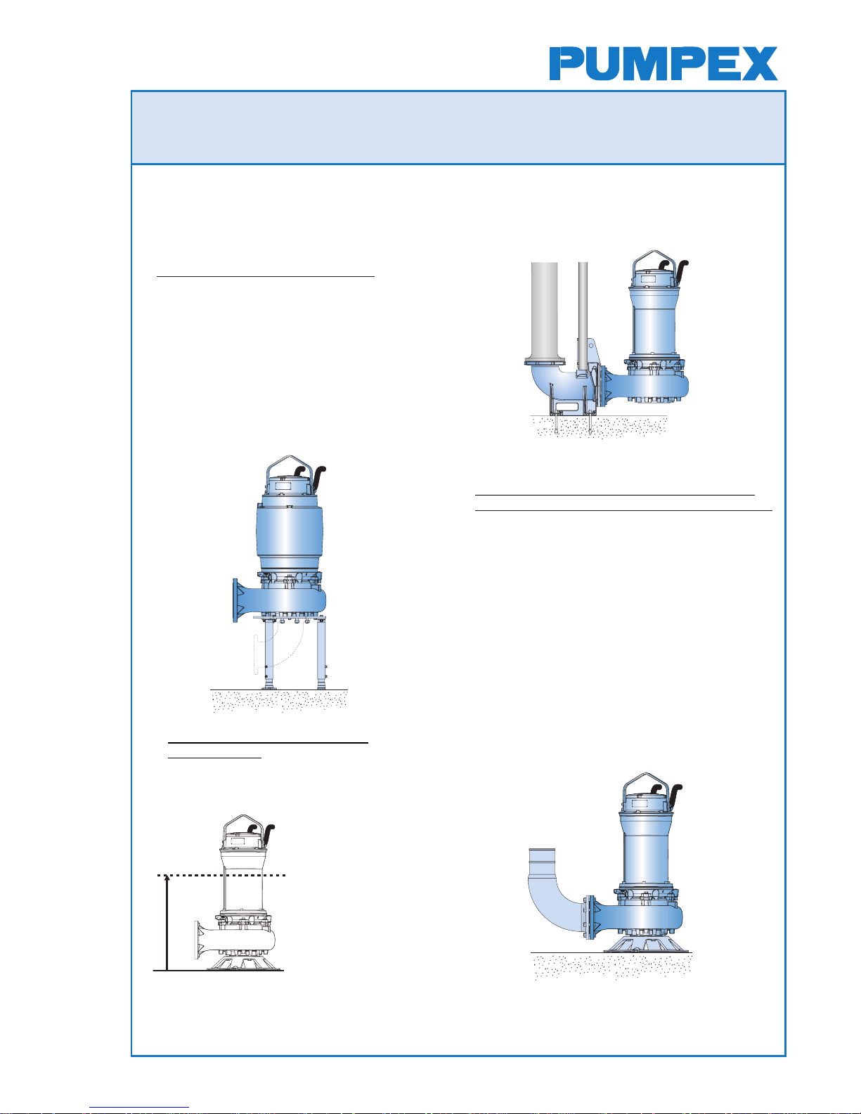
Type F Wet Pit Installation
Installed on a guide rail system with a quickrelease base elbow, the base elbow is bolted
to the floor of the sump. The volute is equipped
with an adapter to be connected to the
discharge elbow.
Two twin guide rails are mounted to the
discharge elbow to steer the pump into the
right position when hoisted up and down. In
case of Wet Pit Installation, the driving units
lack an internal, closed loop cooling system.
Type T, Vertical Dry Pit Installation
Type H, Horizontal Dry Pit Installation
Installed with a suction pipe. The pump is
supported by an adjustable fabricated steel
stand, mounted at the factory.
The height of the stand is sufficient for the
standard suction elbow to be used on a flat
floor. The pump volute is drilled or threaded on
the connection-flange and equipped with studs
on the suction-flange. The motors are equipped
with a maintenance-free internal, closed loop
cooling system.
Type P, Wet Pit Portable
Installation
A version of the pump which is suitable for
temporary installations. The pump is
equipped with a fabricated round steel stand
and a discharge spigot
for a hose or threaded
connection. The minimum
water level in the wet
well for continuous
operation should not be
below ¾ of the motor
housing.
For continuous operation
at water levels below the
abovementioned level,
an internal cooling jacket is recommended.
Intermittent operation down to a water level
below the top edge of the volute is not
acceptable.
4 (15)
K 101/151/200/250/300.58.0404.Eng/Digital
SERVICE INSTRUCTION
K 101, 151, 200, 250, 300
○○○○○○
○○○○○○○○○○○○
○○○○○○
○○○○○
○○○
○○○○○○
○○○○○○○○○○
○○○
○○○○○○○
○○○○
Box 5207 S - 12118 JOHANNESHOV SWEDEN
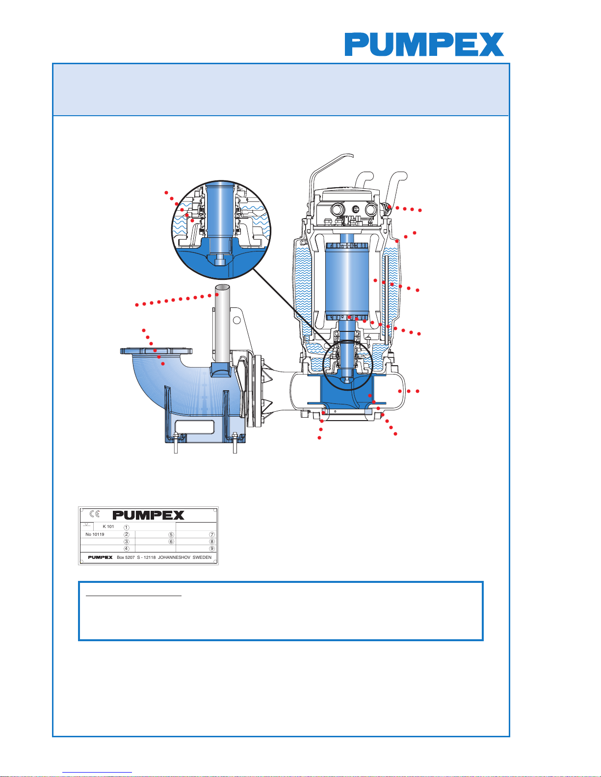
5
6
7
8
9
1
2
3
4
K 101
No 10119999 P.2 45 kW
3 Ph 50 Hz
U 400 V Y n 1465 rpm Class F IP68
I 81 A 717 kg
20 m
Volute
EcoCool
TM
Internal Closed
Loop Cooling
System
Impeller
SmartSeal
TM
Seal Cartridge
Stator Unit
Rotor
Optimizer
TM
Adjustable Wear Ring
Cable Seal
Guide Rails
Discharge Elbow
Safety Precautions
Notice: When performing repairs, the safety instructions in the Service instruction under the
Installation and Operating Instructions, especially the section entitled ”Safety”, must be
observed. When performing any work, appropriately sized and adequately dimensioned hoists
and other tools should be used. Do not work under a suspended load.
Before doing any maintenance or repairs to the pump, make sure that it is isolated from the
power supply and ensure that no one can reconnect it while being worked on. Never move
or lift a pump by using the cable.
If the pump has been working in sewage or similar substance, before working on it, use a
power or steam hose to clean it, and observe personal hygiene precautions.
Electrical work on the pumps should only be performed by qualified personnel.
1 Type of pump
2 Serial Number
3 Working voltage
4 Rated current
5 Rated power
6 Speed of rotation
Notice! Standard nameplate
7 Frequency
8 Winding Class
9 Weight

5 (15)
K 101/151/200/250/300.58.0404.Eng/Digital
SERVICE INSTRUCTION
K 101, 151, 200, 250, 300
Minimizing the Environmental Impact
A life cycle analysis shows that the larger part of the environmental impact caused by
pumps arises in the operating phase. In the five categories of environmental impact, the
operating phase constitutes the major part. The operating phase is vitally important,
especially in the case of greenhouse gases discharging. This is due to the energy that the
pump is using while in operation.
Therefore, it is important to operate the pump with as little energy as possible, which, in turn,
helps to reduce the operating costs.
Points to be Observed:
1. Choose a pump that has the best efficiency and the duty point should be as near as
possible to the best efficiency.
2. Do not choose a pump that is too big.
3. Adjust the wear ring against the impeller when the flow significantly decreases.
4. Change the parts if it is not possible to adjust the pump flow to the original value.
General Maintenance Advice
Before assembling, all parts should be carefully checked.
Parts being reused must be in perfect condition and carefully cleaned before fitting.
The pump and its electrical cables must be disconnected from any power source
by a qualified electrician before any inspection or service is performed!

6 (15)
K 101/151/200/250/300.58.0404.Eng/Digital
SERVICE INSTRUCTION
K 101, 151, 200, 250, 300
Oljeavtappning
Motor
Oljepåfyllning
○○○○○○○
DISASSEMBLING
Removal from the Wet Well
Hoist the pump from the sump and rinse it clean.
Disassembling the Volute
The motor unit is connected to the volute with six
bolts. Loosen the locking screws, turn the latch bolts
90
o
and lift off the motor unit from the volute.
(Fig. 1-2)
Adding and Changing the Oil
The oil housing of PUMPEX wet pit pumps is filled
with oil at the plant.
Type of Oil:
White Oil (e.g. Enerpar M002 or Similar).
Oil Amount:
4 dl (0.9 US pints) F - T – P installation
5 dl (1.1 US pints) H - installation
Remove the plug marked ”oil out” and slant the pump
slightly forward. Let the old oil pour out through the
groove under the plug. Then loosen the plug marked
”oil in” to facilitate the oil draining out. Gather the old
oil in the can. Fasten the plug so that the lower, not
the top O-ring gasket becomes sealed.
Fill new oil in "oil in" and fasten the plugs.
Inspect the motor housing to see if it is dry by
removing the screw marked ”motor”. Tilt the pump
slightly. If water, oil or other debris is present in the
motor housing, a full dismantling is required. (Fig. 3)
Fig 1
Fig 2
Fig 3
QuickLock
TM
Latch Bolts
Oil filling
Oil out
Motor

7 (15)
K 101/151/200/250/300.58.0404.Eng/Digital
SERVICE INSTRUCTION
K 101, 151, 200, 250, 300
Changing the Cooling Liquid
First disassemble the motor unit from the volute.
Pump Without Cooling Jacket:
Loosen the cooling liquid plug down on the cooling plate. Open
the plugs on top of the oil housing and let the old water pour out.
Replug the lower plug on the cooling plate. Slowly fill the new
cooling liquid into one of the holes on top of the oil housing. Let
both plugs on the top open to avoid air bubbles which will obstruct
the filling.
Note! Do not forget to tighten the plugs after filling is
complete.
Pump Without Cooling Jacket - Cooling Liquid, Quantity:
5.5 l (11.6 US pints)
30% Propylene glycol DOWCAL ® 20
Pump With Cooling Jacket:
Loosen the cooling liquid plug down on the cooling plate. Open
the plugs on top of the cooling jacket and let the old water pour
out into a can. Replug the lower plug on the cooling plate. Slowly
fill the new cooling liquid into the hole marked ”in” on top of the
cooling jacket. Let both plugs on the top open to avoid air bubbles
to obstruct the filling.
Note! Don´t Forget to Tighten the Plugs after Filling is
Complete.
Inspection of the Terminal Board Area
Remove the four screws that hold the cover in place. Lift the
cover carefully. To make it easier, the cable cover can be
loosened so that the O-ring gasket does not continue to seal.
Pump With Cooling Jacket - Cooling Liquid, Quantity:
Motor Liter US pints
50Hz:
22kW-4, 30kW-4 18.5kW-6 49.5 105
37kW-4, 45kW-4, 22kW-6, 30kW-6
37kW-6, 15kW-8 44.0 93
60Hz:
25kW(33Hp)-4, 35kW(47Hp)-4, 22kW(29Hp)-6 49.5 105
43kW(57Hp)-4, 52kW(69Hp)-4, 25kW(33Hp)-6
35kW(47Hp)-6, 43kW(57Hp)-6, 17kW(23Hp)-8
22kW(29Hp)-8, 25kW(33Hp)-8, 35kW(47Hp)-8 44.0 93
(30% Propylenglykol DOWCAL® 20)

8 (15)
K 101/151/200/250/300.58.0404.Eng/Digital
SERVICE INSTRUCTION
K 101, 151, 200, 250, 300
Disassembling the Terminal Housing
Disassemble cover as instructed above.
Remove the six screws that hold the terminal housing in place.
Loosen the cables coming out of the motor unit from the terminal
block. The cable lugs have to be removed before cables can be
pulled through the cable seals. Lift the housing carefully.
Note! Always Check how the Cables are Connected
Inside the Block.
Disassembling the Cooling Jacket
Disassemble terminal housing as instructed above. Use the two
M10 holes on the top of the cooling jacket to lift off the cooling
jacket. If needed, use eyebolts for help.
Note! If only the Bearing and the Seal Have to be
Disassembled, the Cooling Jacket May Stay in Place then Disassemble Only the Terminal Housing as
Described Above.
Disassembling the Impeller
The impeller is bolted to the shaft with a flat key and a bolt.
Securing the impeller with a pipe or similar tool, remove the
impeller bolt with a wrench (Fig. 4). To loosen the impeller, it
often helps to pry with a couple of strong screwdrivers between
the impeller and the cooling plate.
Disassembling the Seal Cartridge
Disassemble volute and impeller as instructed above, and empty
the pump of cooling liquid and oil. Lay the motor unit on its side.
Remove the four screws that holds the seal cartridge. The
cartridge can be removed from the oil chamber by inserting two
M8 screws (40 mm (1
9
/16") long) into the ”jacking holes” in the
cartridge or a M8 threaded plug, which will force the cartridge
from the housing (Fig. 5).
Changing the Stator Unit
If the motor protection trips repeatedly, the stator has to be
overhauled. Disconnect the pump from the electric box. Check
the isolation resistance of the motor at the loose end of the cable.
Use a megger.
Fig 4
Fig 5

9 (15)
K 101/151/200/250/300.58.0404.Eng/Digital
SERVICE INSTRUCTION
K 101, 151, 200, 250, 300
Stator med
urpressningsverktyg
If using a 500 V megger the insulation resistance shall exceed
0.5 megaohm. This applies to phase-to-phase readings as well
as between each phase to ground. If the insulation resistance is
less than 0.5 megaohm, the stator should be dried in an oven.
Also check the resistance in the stator. Disconnect the stator
cables from the terminal block and measure directly at the stator
cables.
Note! Notice How the Cables are Connected on the
Terminal Block.
Also check the circuit with the three built-in thermal overload
switches using a buzzer or a bell. If the circuit is open, probably
one of the overload switches is defective.
If the stator still cannot be used, it has to be replaced. Disconnect
the stator from the outgoing cables and disassemble it. Order an
exchange stator unit from the nearest Pumpex Service Center.
Disassembling the Stator
Disassemble the terminal housing as instructed above.
Remove the six screws that hold the stator casing. Use three
M16 screws and thread them into the three threaded holes at the
lower flange so that the stator unit is lifted up from the oil housing.
Gently, with a hoist (recommend Eyebolt M16),lift the stator
casing from the rotor/shaft. Note! Disconnect the cable from the
moisture sensor in the oil housing before the stator is totally lifted
up. Put the stator unit on a distance tube.
Place the pressure tool on the stator and pull the stator out of the
casing (Fig. 6).
Note! Record the Distance from the lower edge of the
Stator Housing to the Edge of the Stator Before the
Stator is Pressed Out.
Stator with
Pressure Tool
Fig 6

10 (15)
K 101/151/200/250/300.58.0404.Eng/Digital
SERVICE INSTRUCTION
K 101, 151, 200, 250, 300
Disassembling the Rotor and Ball Bearings
The rotor is mounted in the motor unit with an upper and two
lower bearings. Install the eyebolt (M16) into the drilled hole in the
shaft (Fig.7).
Carefully lift out the rotor with the upper bearing from the oil
housing. Bearings that have been in contact with water or are
damaged should
always be replaced.
Fasten the rotor in a vice with soft jaws. Clean the shaft and
lubricate it. Place the withdrawing tool on the upper bearing and
make sure it pulls the inner ring. Remove the bearing.
If the lower bearings are on the shaft, pull them off with your
hands. Pick up the lower bearings if they are still in the oil
housing.
ASSEMBLING
Mounting
While mounting the motor unit, be extremely careful and make
sure everything is clean. Clean all O-ring grooves and all other
contact surfaces carefully. Use a wire brush when necessary.
Lubricate all O-rings with oil or grease to prevent the O-rings
from getting stuck or damaged when remounting. Also, lubricate
all threads on the screws to facilitate disassembling when
servicing next time.
Mounting the Ball Bearings
Check that the shaft is straight and the key slot is not damaged.
Polish deep scratches and burrs off. Push the upper bearing into
place. If a press is not available, heat the bearing to 100-120°C
(212-248°F) in an oilbath.
Wipe off the shaft contact surfaces of the bearing and mount it.
Mount the lower bearings in the oil housing by using a pipe with
the same external diameter as the bearing external diameter in
order to keep the bearings in place in the oil housing when the
rotor is mounted (Fig. 8).
NB! Do not Forget to Refill the Bearings with Grease.
Fig 7
Fig 8

11 (15)
K 101/151/200/250/300.58.0404.Eng/Digital
SERVICE INSTRUCTION
K 101, 151, 200, 250, 300
Stator med
inpressningsverktyg
Mounting the Rotor in the Oil Housing
Heat the oil housing before mounting the rotor (Fig. 9). Lift the
rotor carefully in place with help of an eyebolt (Fig.10).
Mounting the Stator
Push the stator in with the pressure tool (Fig. 11).
Note! Remember the Measurement taken from
”Dismounting the Stator”.
Pull the cables from the stator through the cable seals on the
terminal housing. Connect the cables onto the terminal block
according to the wiring diagram on page 14. Put the terminal
housing with the O-ring in their place.
Let the oil housing with rotor cool down so that the bearings will
take hold. Erect the oil housing and clean all contact surfaces
between the oil housing and the stator unit with a wire brush.
Lubricate and mount a new O-ring in the oil housing. The stator is
now ready to be mounted on the oil housing. Note that space is
required for the shaft end when it sticks out after mounting.
Lift the stator unit with a lift device and carefully lower it over the
rotor. Do not forget to reconnect the cable to the moisture sensor
in the oil housing. Check that the rotor does not damage the
windings or the stator core. Fasten the stator with the six screws.
Note! Be sure that the Cooling Channel Holes in the
Stator Housing are in line with Cooling Channels/Plugs
in the Oil Housing.
Mounting the Seal Cartridge
Put down the motor unit. Lubricate the shaft and all four O-rings
on the seal unit (three external on the seal housing and one
internal in the seal sleeve).
Push the seal unit onto the shaft, and carefully place it in position.
Do not use hard striking tools. Tighten the seal unit by
fastening the four screws.
NOTE! If the Seal is Mounted, Never Run the Motor
Without Having the Impeller Mounted. This Can Cause
Damage to O-rings in the Seal.
Stator with the
Pressure Tool
Fig 11
Fig 10
Fig 9

12 (15)
K 101/151/200/250/300.58.0404.Eng/Digital
SERVICE INSTRUCTION
K 101, 151, 200, 250, 300
Mounting the Impeller
Turn the shaft so that the key slot is upward. Put the key in its
groove and push the impeller onto the shaft. Lock the impeller to
prevent it from rotating with a pipe or similar tool and fasten the
impeller washer and screw (Fig.12). For the torque rating, see
page 15.
Mounting the Cooling Jacket
Lubricate the O-ring on the oil housing and the O-ring on the
upper inside of the cooling jacket. Lower the cooling jacket over
the stator housing. The cooling jacket can be placed optionally so
that the filling holes are in suitable position.
Mounting the Cable Seal
If water has gotten through the cable seal to the terminal board,
the cable seals have to be replaced. The cable seal should be
replaced after every disassembly of the cable gland. Measure
the cable diameter with a slide gauge and compare it to the holes
in the cable seal and the washers so that the dimensions are
identical.
Pull the seal onto the cable with one washer on each side (Fig.
13). Pull the cable through the cover so that the cable and its
cover extends through the cable gland and into the terminal area
when tightening the cable lead-in. After tightening, the strain relief
clamp is fastened. Turn the clip´s long pin down to prevent the
cable lead-in from unthreading.
Mounting the Terminal Housing
Pull the cables through from the stator unit and fasten the
terminal housing with six screws.
Remember that the Ground Cable by Safety Standards
Should be Longer than the Other Cables.
Ensure that the cables are not pinched. Connect the cables
according to the wiring diagram on page 14.
Mounting the Cover
Grease the O-ring on the cover and fasten it with four screws. In
order to facilitate mounting the cover, one of the cable covers can
be loosened so that air can be pressed out and release the
pressure. Tighten the loosened cable cover.
Fig 13
Fig 12

13 (15)
K 101/151/200/250/300.58.0404.Eng/Digital
SERVICE INSTRUCTION
K 101, 151, 200, 250, 300
Mounting the Motor Unit to the Volute
Turn the latch bolts so that the motor unit runs free down to the
upper edge of the volute. Turn the latch bolts in and fasten the
screws alternately. For the torque rating see page 15.
Adjusting the Wear Ring
Lay the pump down on its side and check the clearance in
between the impeller and wear ring. The clearance should be
0.7 mm (
1
/32") maximum. The wear ring is placed on the bottom
side of the volute and is fastened by three screws placed
horizontally (Fig. 14).
Loosen these screws and adjust with the three vertically placed
screws. When necessary, strike carefully with a hammer or
plastic club. When the distance is adjusted, the horizontally
placed screws can be tightened. In case of T/H installation, the
wear ring can be adjusted with three vertically placed screws
from the inside of the volute. This requires, nevertheless, that the
motor unit has been dismounted from the volute.
Note! This Applies Only if Using a Channel Impeller. If
using a Vortex Impeller, do not Adjust the Wear Ring!
Testing
Connect the cables to the electric mains and start the pump. The
arrow on the cover indicates the direction of rotation. The starting
reaction will be in the opposite direction.
Note! Always Check the Lifting Handle and Screws Each
Time the Pump is Lifted Up from the Pit.
Recycling in Case of Scrapping the Pumps
The pump can be disassembled to the material level. Wear parts
made of rubber/ steel have to be treated so that the steel can be
recycled. The cable has to be treated so that the copper can be
recycled. The most positive environmental impact is achieved
when the copper is recycled. Recycling the original components
is profitable. Aluminium, copper, stainless steel, cast iron and
ductile iron should be recycled. White oil should be submitted for
burning and other materials for discarding.
Fig 14

14 (15)
K 101/151/200/250/300.58.0404.Eng/Digital
SERVICE INSTRUCTION
K 101, 151, 200, 250, 300
ÄY
1
2
Y/Ä
3
THERMAL PROTECTION WINDING
MOISTURE SENS. OIL CHAMBER
MOISTURE SENSOR TERMINAL BOARD AREA
Star/Delta starting
THERMAL PROTECTION WINDING
MOISTURE SENS. OIL CHAMBER
MOISTURE SENSOR TERMINAL BOARD AREA
Direct on-line starting
THERMAL PROTECTION WINDING
MOISTURE SENS. OIL CHAMBER
MOISTURE SENSOR TERMINAL BOARD AREA
Direct on-line starting
Wiring Diagram

15 (15)
K 101/151/200/250/300.58.0404.Eng/Digital
SERVICE INSTRUCTION
K 101, 151, 200, 250, 300
Torque Rating
Cable Gland: A specific torque value cannot be given for the cable gland. Tighten it until
the rubber offers resistance, and thereafter, one more full rotation.
Size [Nm] [lb-ft]
M6 7 5.2
M8 17 12.5
M10 33 24.3
M12 57 42.0
M14 91 67.1
M16 140 103.3
Size [Nm] [lb-ft]
Impeller Bolt
198 146
(M16 Bumax)
Latch Bolt
187 138
(M16 A4-80)
 Loading...