

Pumpex K 152, K 252, K 203, K 202, K 302 Service Instructions Manual
K152/202/203/252/302.58.0101.Eng/Digital
K 152, 202, 203, 252, 302
SERVICE INSTRUCTION
1 (15)
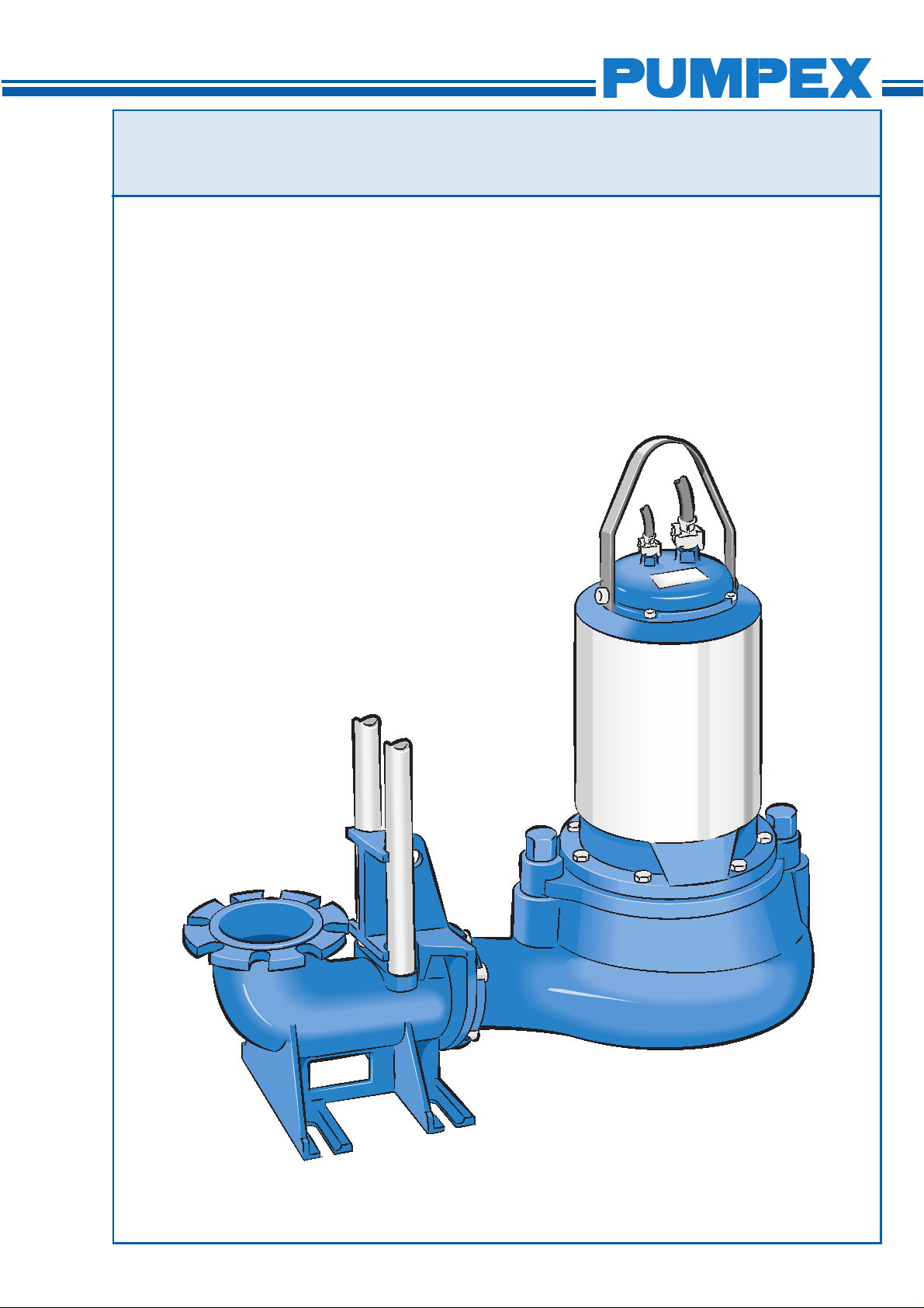
SERVICE INSTRUCTION
K 152, 202, 203, 252, 302
This Service Instruction applies to the following Electric
Submersible Wastewater Pumps: K 152, K 202, K 203. K 252,
K 302.
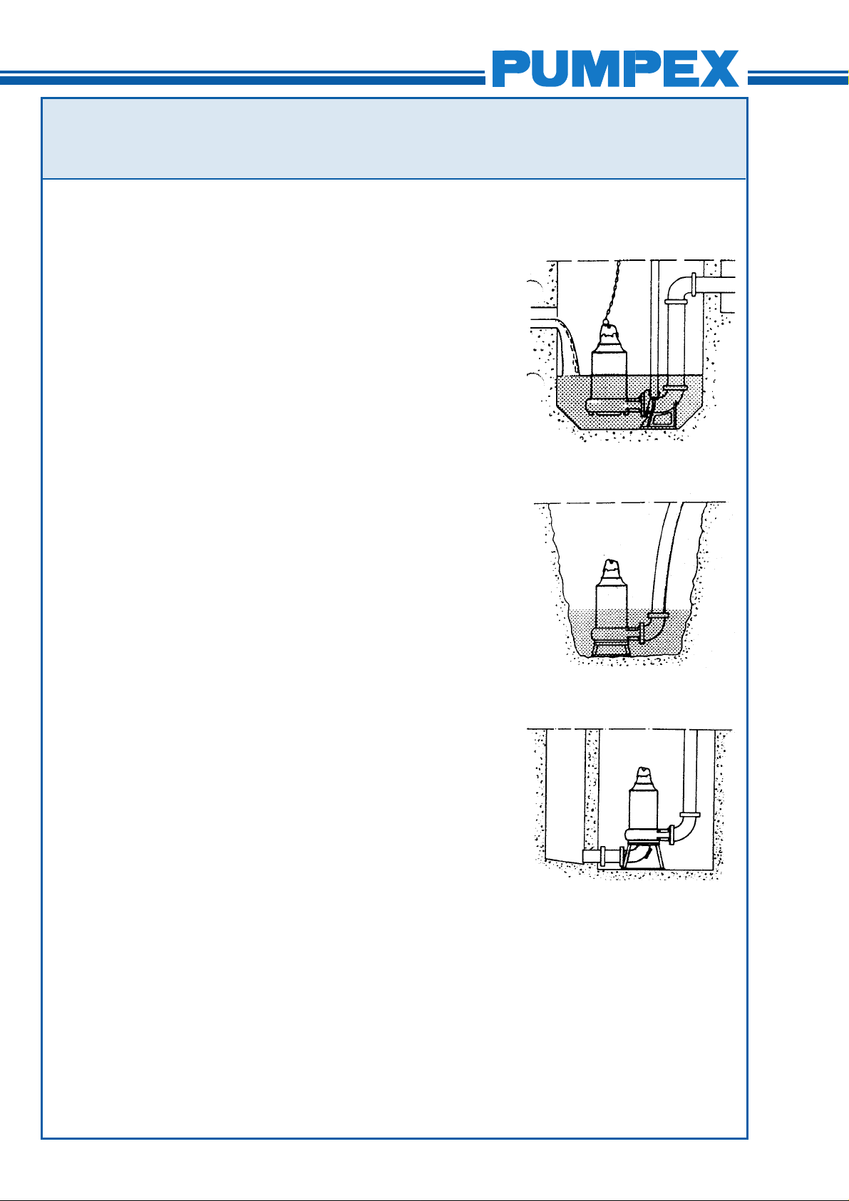
Type F Wet Pit Installation
Installed on a guide rail system with a quick-release base elbow,
the base elbow is bolted to the floor of the sump. The volute is
equipped with an adapter to be connected to the discharge
elbow.
Two twin guide rails are mounted to the discharge elbow to
steer the pump into right position when hoisted up and down.
The motor has an internal cooling system. The motors are
equipped with a maintenance-free internal, closed loop cooling
system which dissipates the heat to the liquid that is being
pumped.
K152/202/203/252/302.58.0101.Eng/Digital
Installed below liquid level with discharge elbow
Type T, Dry Pit Installation
Installed in a normally dry well, but still fully submersible. The
pump is supported by an adjustable fabricated steel stand,
mounted at the factory. The height of the stand is sufficient for
the standard suction elbow to be used on a flat floor.
The pump volute is drilled or threaded on the connection-flange
and equipped with studs on the suction flange. The motors are
equipped with a maintenance-free internal, closed loop cooling
system which dissipates the heat to the liquid that is being
pumped.
Type P, Wet Pit Portable or fixed installation
A version of pump which is suitable for temporary or permanent
installations. The pump is equipped with a fabricated steel stand
and either a threaded (BSP, NPT) or plain hose connection.
The motors are equipped with a maintenance-free internal,
closed loop cooling system which dissipates the heat to the liquid
that is being pumped.
Installed below liquid level, either
stationary or for portable
Dry installation with cooled motor.
Suction bend provided with cleaning
cover.
2 (15)
SERVICE INSTRUCTION
K 152, 202, 203, 252, 302
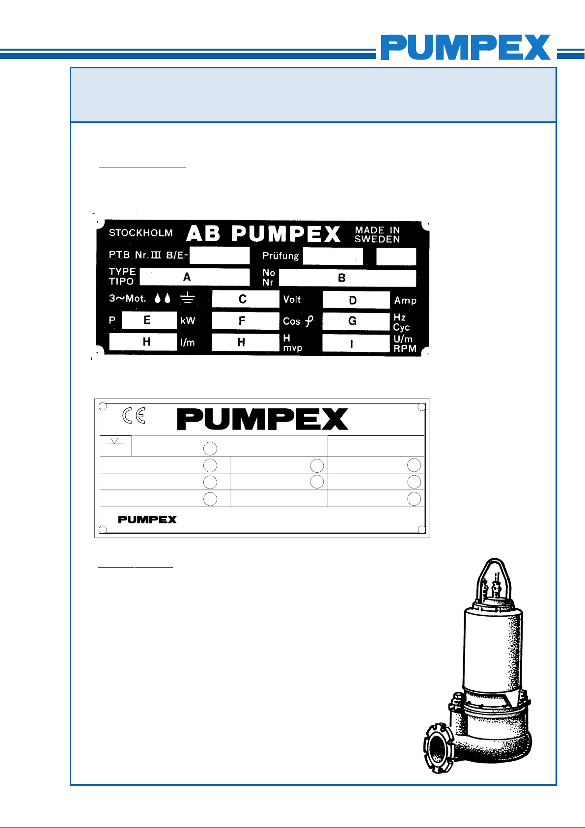
Technical data
The technical data are stamped on the data plate, which is
located under the pump handle.
K152/202/203/252/302.58.0101.Eng/Digital
A Type of pump
B Serial number
C Working voltage
D Rated current
E Rated output
F Cos ϕ
G Frequency
H Head
I Speed
20 m
No 99999999 P.2 2.0 kW
U 400 V Y n 1385 rpm Class F IP68
I 5,4 A 98 kg
K 80
1
2
3
3 Ph 50 Hz
5
6
4
Box 5207 S - 12116 JOHANNESHOV SWEDEN
Pump design
The design of the pump features high reliability and easy maintenance. The major parts of the pump are few in numbers and do
not require special tools during disassembly and assembly.
The electric motor unit consist of Stator Unit (Stator and Stator
Housing), Rotor Unit (Rotor, Shaft and Bearings) Impeller, Oil
Housing, Mechanical Shaft Seal Unit and Junction Box (Junction
Box Cover, Terminal Board and Cable Entries).
The motors are always equipped with a maintenance-free
internal, closed loop cooling system which dissipates the heat to
the liquid that is being pumped.
1 Type of pump
2 Serial number
3 Working voltage
4 Rated current
7
8
9
5 Rated output
6 Engine speed
7 Frequency
8 Winding class
9 Weight
An exchange system is used for the Stator Unit and Mechanical
Shaft Seal Unit.
3 (15)
SERVICE INSTRUCTION
K 152, 202, 203, 252, 302
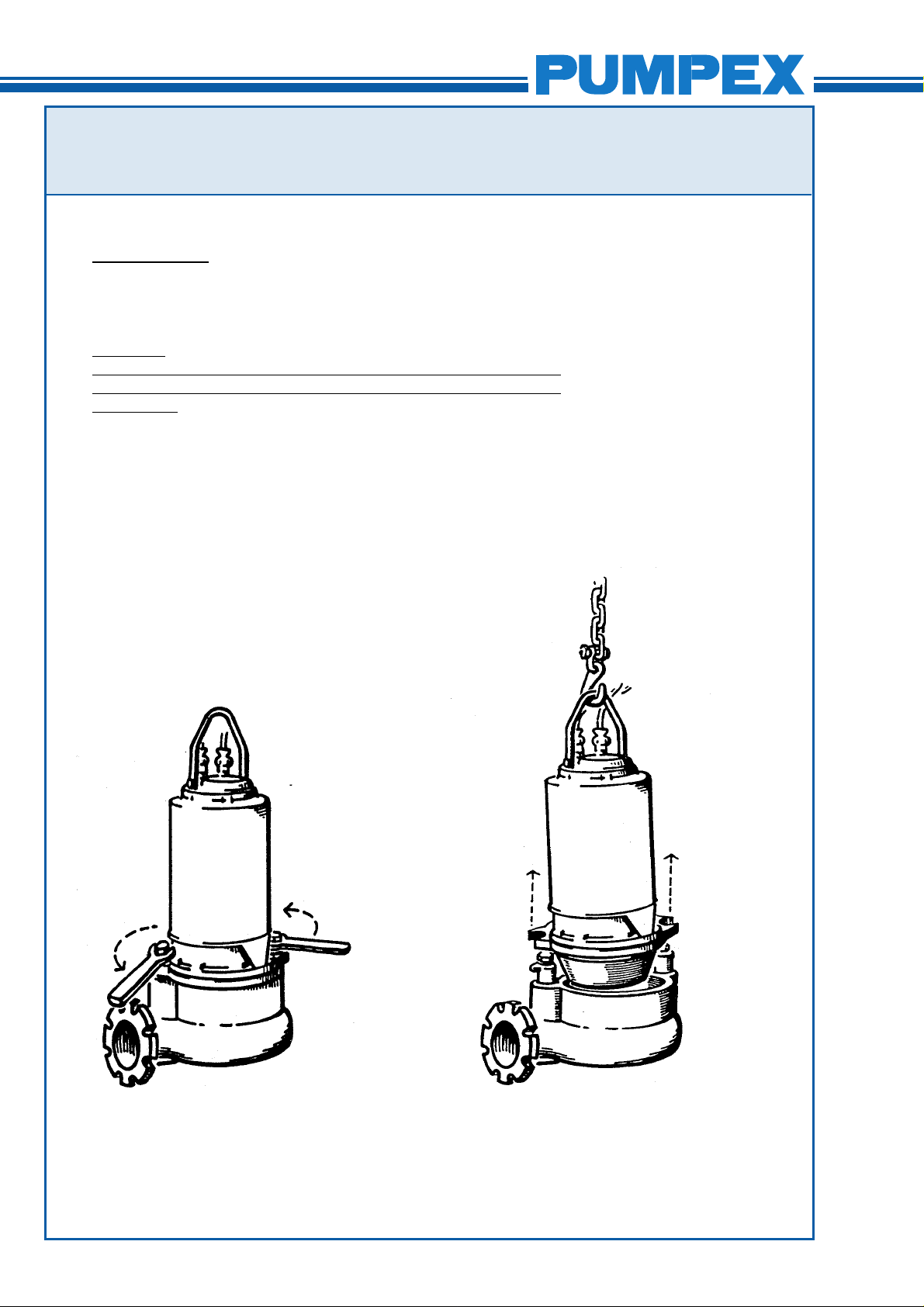
Disassembly
Remove the pump from the pit and rinse it with water.
Warning!
Always check that the pump is disconnected from the electric
power supply and cannot be energized, prior to any work being
carried out.
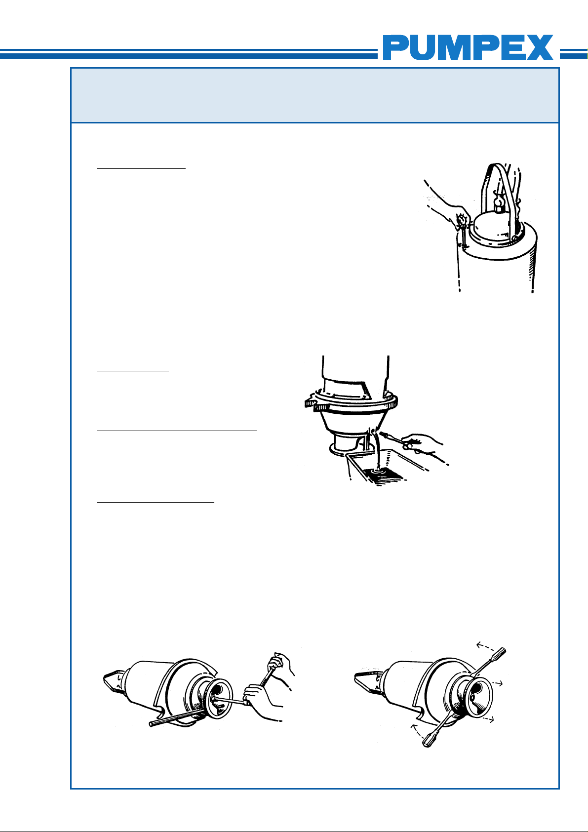
The motor unit is assembled to the volute by two (2) latch bolts.
Loosen the latch bolts with a wrench (supplied with the pump)
and turn the latches free from the flange of the motor unit. The
motor unit can now be separated from the volute.
K152/202/203/252/302.58.0101.Eng/Digital
4 (15)
SERVICE INSTRUCTION
K 152, 202, 203, 252, 302
Exchange of oil
Exchange of oil should be carried out if the oil is discoloured by
water or when a complete overhaul is done.
Place the motor unit on the floor or a low work bench. Loosen
the oil stick carefully to relieve over-pressure in the oil chamber.
Tighten oil stick again and loosen the oil plur, on the oil housing.
Regulate the oil flow by loosening the oil stick to allow air into
the oil chamber. Tilt the motor unit to drain all the oil from the oil
housing.
Replace the 0-rings for oil plug and oil stick and tighten the oil
plug. Fill new oil through the hole for the oil stick.
Oil type: Enerpar M002, or similar.
Oil quantity:
K152/202/203/252/302.58.0101.Eng/Digital
11-15 kW motor - 14.5 litres
23-40 kW motor - 18.5 litres
Don´t forget to tighten oil stick.
Removal of Impeller
The impeller is fitted on a cylindrical shaft end. To simplify the
loosening of the impeller bolt, place a piece of wood (pipe or
similar) inside the impeller to keep it from rotating. Loosen the
impeller bolt with a socket wrench (socket 22 mm).
The impeller has a relatively light fit on the shaft and is using a
flat key. The impeller can be removed by using two (2) pry bars
or large screwdrivers.
5 (15)
 Loading...