

PulseWorx WS1D, WS1R, WS1DL, WS1E, RWS Quick Start Manual
Quick Start Guide
Wall Switch Products
WS1D, WS1DL, WS1R, WS1E, RWS
MODELS:
WS1D - Wall Switch Dimmer – For Incandescent, Halogen,
Fluorescent, Inductive and Magnetic LV Loads.
WS1DL – Wall Switch Dimmer - For LED, CFL, Incandescent,
Halogen, Fluorescent, Inductive and Magnetic LV Loads.
WS1R – Wall Switch Relay – For heavier loads up to 20A, motors,
pumps or ceiling fans that may hum when using a dimming switch.
WS1E – Electronic Low Voltage Dimmer – For Electronic Low
Voltage Capacitive Transformers only. This is a Reverse Phase
Dimmer.
RWS – Remote Wall Switch – For 3-way applications
FUNCTION
PulseWorx products are designed to provide simple remote
control for lighting and other electrical loads without having
to run any new wiring. They connect (or “link”) to one another
by communicating over the existing electrical power wires.
The WS1 Wall Switch series is a high quality light-switch/dimmer
that not only allows for local rocker switch control of a lighting
load but also incorporates PCS’s innovative UPB® two-way
powerline communication technology that gives it the ability to
be remotely controlled by other UPB® compatible controllers.
The WS1 is highly configurable to allow for behaviors customized
to each individual’s desires. The WS1 is capable of storing up to
16 preset light levels and fade rates to create powerful lighting
scenes. The WS1 is also capable of transmitting UPB® messages
(including a current light level report) when rocker switch events
occur.
The RWS Remote Wall Switch (Figure 2) is an optional low cost
accessory to the WS1. The RWS acts like a secondary Decorastyle rocker switch for replacing or creating a three-way
lighting control circuit. The RWS connects to the load
controlling device (WS1) through the single yellow traveler
wire normally found in a traditional three-way lighting control
circuit.
IMPORTANT SAFETY INSTRUCTIONS
When using electrical products, basic safety precautions
should always be followed, including the following:
1. Keep away from water. If the product comes in contact
with water or other liquid, turn off the circuit breaker and
remove the product immediately.
2. Never use products that have been dropped or damaged.
3. Do not use this product outdoors.
4. Do not use this product for other than its intended purpose.
5. Do not cover this product with any material when in use.
AIR-GAP SWITCH
The WS1D/DL/E rocker switches have an air-gap switch that will
remove all power from the load for safe installation and bulb
replacement. To activate the air-gap switch firmly press the rocker
bottom until you hear a loud “click” or you see the SYSTEM “OFF”
label on the top rocker.
INSTALLATION
Follow these instructions to replace an existing wall switch with
a WS1:
1. Before installing the Wall Switch into a wall box, ensure that
power to the wall box has been disconnected by removing the
fuse or turning the circuit breaker off. Installing products
while the power is on may expose you to dangerous voltage
and may damage the product.
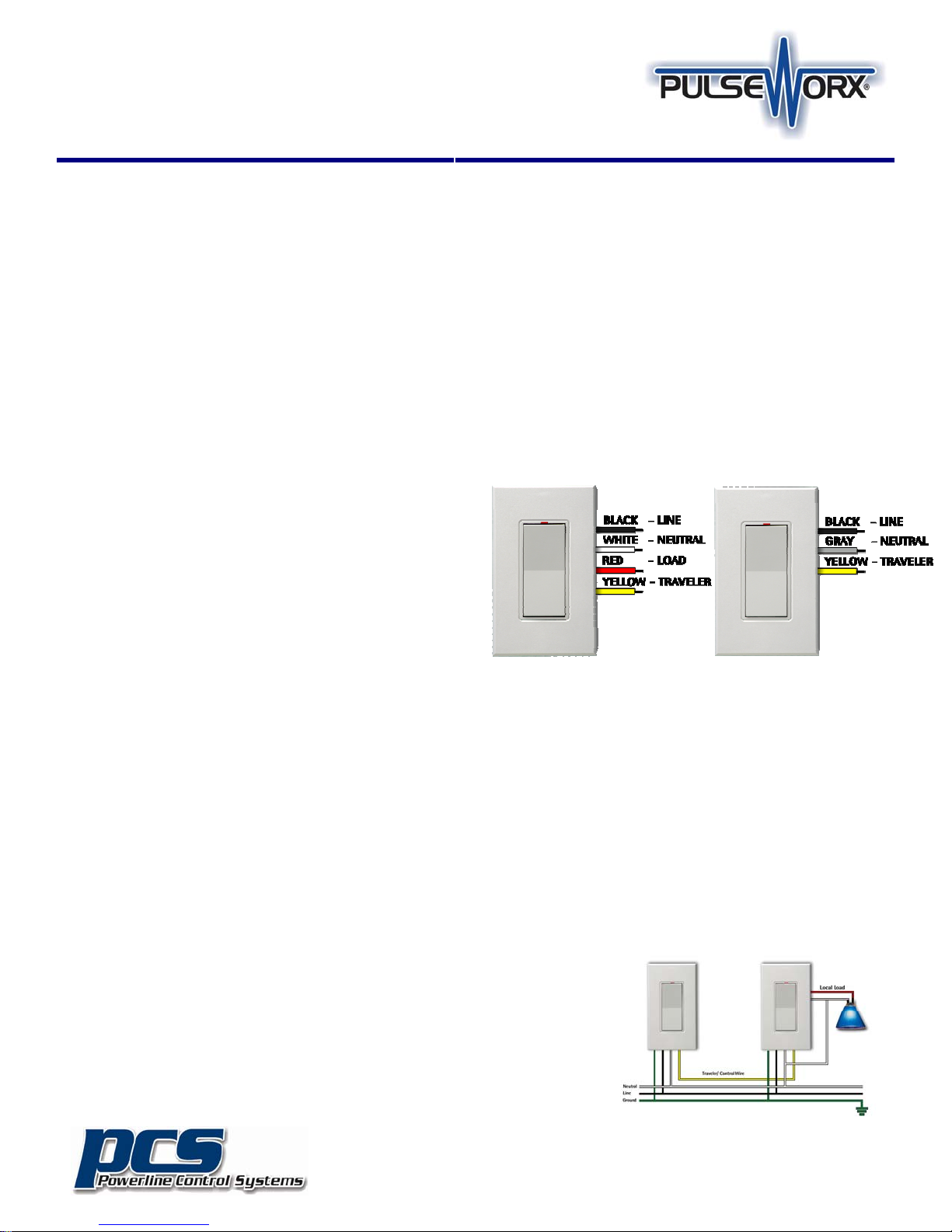
WS1 RWS
Figure 1 Figure 2
2. Remove the faceplate from the existing wall switch, then
unscrew and pull the existing wall switch out of the wall box.
3. Disconnect the wires from the existing wall switch. Identify
the “Line”, "Neutral", “Load" and “Control/Traveler” wires.
4. Wire the PulseWorx Wall Switch and any RWS connecting
wires per wiring configuration shown in Figure 3. Cap off any
unused wires from the device
5. Gently place the wires and Wall Switch into the wall box, with
light emitting diode (LED) at the top of device. Screw in place.
6. Before installing the faceplate, restore power to the circuit
and test the device for proper local operation.
7. After testing, re-install the faceplate cover(s).
WIRING DIAGRAM
RWS
WS1
©2012 Powerline Control Systems, Inc.
All Rights Reserved v2.0
19201 Parthenia St. Suite J
Northridge, CA 91324
P: 818.701.9831 F: 818.701.1506
pcssales@pcslighting.com
www.pcslighting.com
Quick Start Guide
Wall Switch Products
WS1D, WS1DL, WS1R, WS1E, RWS
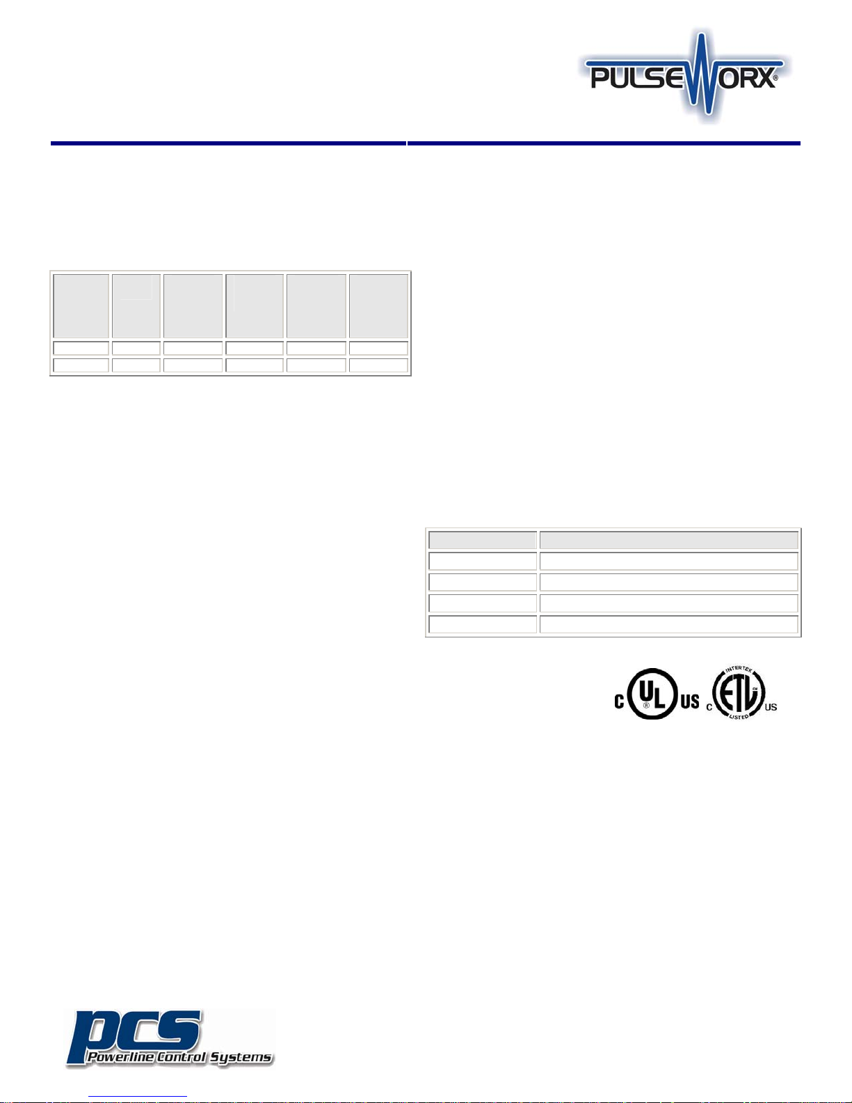
DE-RATING INFORMATION FOR WS1D
For a proper fit in a multiple gang installation, it may be
necessary to remove one or both sides (break-off tabs) from the
mounting plate. When tabs are removed, the overall rating of
the device must be reduced in accordance with the following
chart:
Model Max
Load
WS1D-6 600W 600W 600W 500W 400W
WS1D-10 1000W 900W 1000W 800W 600W
MULTI-WAY CIRCUITS
The Wall Switch is wired directly to the lighting circuit and can
(optionally) be controlled by one or more RWS Remote Wall
switches producing three, four or five-way circuits. Multi-way
circuits make it possible for a group of switches to control the
same set of lights. This section will illustrate how to wire the
connections.
Note:
1. Refer to Figures 1 and 2 to determine the wire colors of the connections.
2. All PCS Wall Switches require a neutral (white) connection.
3. Remote Wall Switches require that the Line (black) wire be accessible. This wire
may be connected to either phase of the 120/240V supply.
4. The gray wire on the Remote Wall Switch can be connected to either earth
ground or neutral. The gray wire serves only to light the LED in the remote. This
LED does not indicate anything except that power is applied and to serve as a
night-light.
No Fins
Removed
Normal
Depth
Box
No Fins
Removed
Deep Box
One Fin
Removed
or Next
to One
Dimmer
Both Fins
Removed
Or Next
to Two
Dimmers
SETUP MODE
When configuring a UPB system, it will be necessary to place the
WS1 in SETUP mode. To do this, tap the Rocker Switch five times
rapidly. The lighting load will flash one time and the Status LED
will continuously blink Blue when the device is in SETUP mode. To
exit SETUP mode, tap the Rocker Switch once or wait five minutes
for it to time out.
OPERATION
The WS1 can be a member of up to 16 scenes with the capability to
store a pre-set relay state (on, off, or blink) for each scene. The
WS1 will accept powerline commands from any UPB-compatible
transmitter such as PulseWorx Keypad Controllers, Timed Event
Controllers, Wall Switches, Interface Modules, and approved ThirdParty Controllers.
STATUS LED INDICATOR
The WS1 comes equipped with a multi-color status LED indicator
that is normally lit to blue. This LED indicator will blink different
colors to indicate UPB ® communication status and configuration
status as outlined below.
LED can also be configured to stay one solid color or to change colors based on the
state of the load.
Note: By using UPStart Setup Software, the Status
LED Color Status
BLUE Power applied to Wall Switch
MAGENTA Receives message for Wall Switch
BLACK Receives message for another device
RED Switch is transmitting a UPB® message
CONFIGURATION
Once your WS1 is installed it can be configured either manually
or with the UPStart Setup Software.
Manual configuration can be used to add your WS1 device into a
UPB network and link it to controller buttons. Refer to the
Keypad Controller’s Manual Configuration Guide for more
details.
Although the factory default operation of the WS1 is useful in
many situations, it is highly recommended that your device be
configured with UPStart Setup Software so that you can take
advantage of its many configurable features.
PCS has developed a Powerline Interface Module (PIM) and free
UPB Setup Tool software (UPStart) to help you configure all of
your PulseWorx Lighting System devices. User’s Guides are
available to explain how to configure your system from our
website.
CERTIFICATION
This product has been
thoroughly tested by either
Underwriters Laboratories or
Intertek Testing Services, nationally recognized independent thirdparty laboratories. The North American UL/ETL Listed mark signifies
that the product has been tested to and has met the requirements
of a widely recognized consensus of US and Canadian product
safety standards, that the manufacturing site has been audited,
and that the manufacturer has agreed to a program of quarterly
factory follow-up inspections to verify continued conformance.
LIMITED WARRANTY
Seller warrants this product, if used in accordance with all
applicable instructions, to be free from original defects in materials
and workmanship for a period of five years from the date of
purchase. Refer to the warranty information on the PCS website
(www.pcslighting.com) for exact details.
©2012 Powerline Control Systems, Inc.
All Rights Reserved v2.0
19201 Parthenia St. Suite J
Northridge, CA 91324
P: 818.701.9831 F: 818.701.1506
pcssales@pcslighting.com
www.pcslighting.com
 Loading...