

PulseWorx KPLD7, KPLR7 Installation Manual And Owner's Manual
Models: KPLD7/KPLR7
Installation Guide and
Keypad Load Controllers
FUNCTION
The Keypad Load Controller Series are an all in one Keypad
Controller and Light Dimmer/Relay in a single package. They are
able to transmit and receive UPB® (Universal Powerline Bus)
digital commands over the existing power wiring to remotely
turn on, off, and dim other UPB load control devices. No
additional wiring is required and no radio frequency signals are
used for communication.
Owner’s Manual
6. Do not cover this product with any material when in use.
7. This product uses polarized plugs and sockets (one blade is
larger than the other) to reduce the risk of electric shock.
These plugs and sockets fit only one way. If they do not fit,
consult an electrician.
8. SAVE THESE INSTRUCTIONS.
INSTALLATION
The Keypad Load Controllers are designed for indoor use. To install
the KPL module in a wallbox follow these instructions:
1. Before installing the KPL into a wall box, ensure that power
to the wall box has been disconnected by removing the fuse
or turning the circuit breaker off. Installing products while
the power is on may expose you to dangerous voltage and
may damage the product.
2. Remove any existing wall plate and device from the wall box.
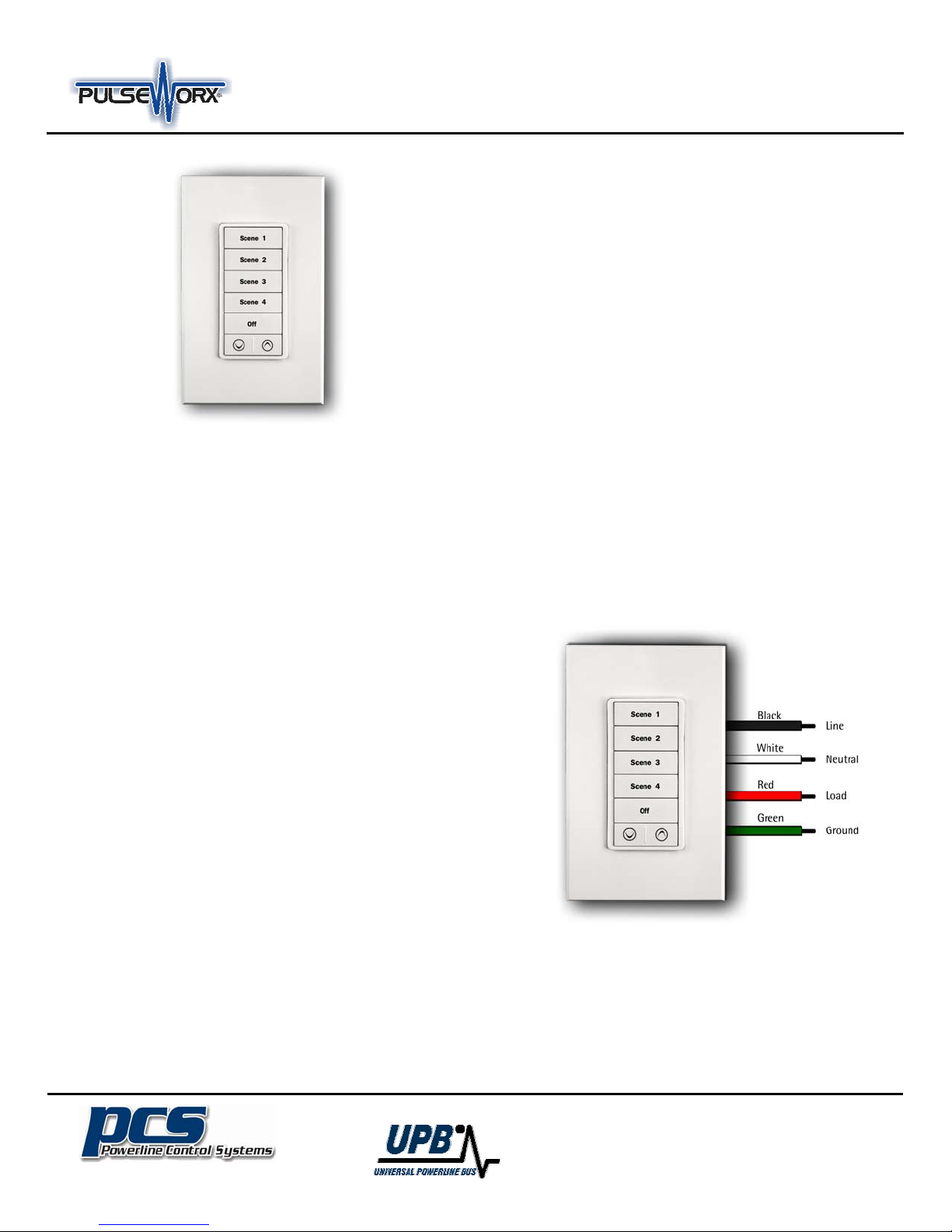
3. Use wire nuts to securely connect the KPL’s white wire to the
“Neutral” wire, the KPL’s black wire to the “Line” wire and the
red wire to the “Load” wire (see illustration below).
4. Fit the KPL into the wall box and secure with mounting
screws. Install the wall plate.
5. Restore power at the circuit breaker.
Models
The KPL is available in two different models: The KPLD Dimmer
has a built in dimmer rated at 400W and the KPLR Relay is the
relay version able to handle 8 Amps. Both can be mounted in
any wall box that contains neutral, line, load and ground wires.
Available colors are White, Black, and Light Almond.
Engraved Buttons
The KPL’s have white backlit buttons engraved with the
designations of: Scene 1, Scene 2, Scene 3, Scene 4, Off, and
an Up Arrow and Down Arrow. Custom Engraved buttons
(model CEB) are available enabling you to tailor each button for
its particular use. Consult your dealer or our website
(www.pcslighting.com) for CEB ordering information.
IMPORTANT SAFETY INSTRUCTIONS
When using electrical products, basic safety precautions should
always be followed, including the following:
1. READ AND FOLLOW ALL SAFETY INSTRUCTIONS.
2. Keep away from water. If the product comes in contact
with water or other liquid, turn off the circuit breaker and
unplug the product immediately.
3. Never use products that have been dropped or damaged.
4. Do not use this product outdoors.
5. Do not use this product for other than its intended
purpose.
The Inventors Of:
19201 Parthenia St. Suite J
Northridge, CA 91324
P: 818.701.9831 F: 818.701.1506
pcssales@pcslighting.com www.pcslighting.com

Models: KPLD7/KPLR7
Installation Guide and
Keypad Load Controllers
CONFIGURATION
Once your KPL is installed it can be configured either manually
or with UPStart Configuration Software Version 6.0 build 57 or
higher.
Refer to the Keypad Controller’s Manual Configuration Guide
available on the PCS website for further details on Manual
configuration to add your KPL device into a UPB network and
link it to various load control devices.
Although the factory default operation of the KPL is very useful
in many situations, it is highly recommended that you program
your KPL with a Powerline Interface Module (PIM) and UPStart
Configuration Software to take advantage of its many
configurable features. User Guides are available on our website,
if you need further assistance on how to configure your system.
SETUP Mode
When configuring a UPB system, it will be necessary to place
the KPL into SETUP mode. To enter Setup Mode, simultaneously
press and hold the Scene 1 and Down Arrow buttons for 3
seconds. All of the LED indicators will blink once the device is
in SETUP mode. To exit SETUP mode, again simultaneously press
and hold the Scene 1 and Down Arrow buttons for 3 seconds or
wait five minutes for it to time out.
Changing a Scene’s Preset Light Levels
The Controllers are specially designed to work with other
PulseWorx® Lighting System devices. Each pushbutton on these
controllers is configured to activate a Preset Light Level and
Fade Rate stored within the PulseWorx devices. The Preset Light
Levels can be easily adjusted by following this simple procedure:
1. Press the pushbutton on the Controller to activate the
currently stored Preset Light Levels (scene) in the Wall
Switch Dimmer(s).
2. Use the local rocker switch on the Wall Switch to set the
new desired Preset Light Level.
3. Rapidly tap the pushbutton on the Controller five times.
4. The WS1D’s lighting load will flash one time to indicate
that it has stored the new Preset Light Level.
Owner’s Manual
Backlit Pushbuttons
Each of the pushbuttons has a White LED behind it to provide
back-lighting and to indicate when loads or scenes are activated.
By default, the back-lighting is enabled and pressing a pushbutton
will cause it to illuminate brighter than the others.
Factory Default Settings
To restore the following default settings put the KPL into SETUP
mode and then simultaneously press and hold the Scene 2 and Off
buttons for about 3 seconds. The indicators will light up to
indicate that factory defaults have been restored.
Network ID:
Unit ID KPLD7:
Unit ID KPLR7:
Network Password:
Receive Sensitivity:
Transmit Count:
IR Options:
LED Options:
Scene 1 Button Mode:
Scene 2 Button Mode:
Scene 3 Button Mode:
Scene 4 Button Mode:
OFF Button Mode:
UP Button Mode:
DN Button Mode:
Load Settings Link 1
Load Settings Link 2
Load Settings Link 3
Load Settings Link 4
Load Settings Link 5
Load Settings Link 6
Load Settings Link 8
LIMITED WARRANTY
255
75
74
1234
High
Twice
N/A
Backlight enabled/ High
Link 1: Link Activate
Link 3: Link Activate
Link 4: Link Activate
Link 5: Link Activate
Link 2: Link Activate
Last Link: Bright Button
Last Link: Dim Button
KPLD / KPLR
100% / 100%
0% / 0%
80% / 100%
60% / 100%
40% / 100%
20% / 100%
Blink .5 Sec/ Blink .5 Sec
OPERATION
Once installed and configured the KPL will operate with the
stored configuration settings. Single-tap, double-tap, hold, or
release the pushbuttons to transmit a preset command onto the
powerline. Refer to the Specification Document (available for
download) for more details about the keypad operation.
Seller warrants this product, if used in accordance with all
applicable instructions, to be free from original defects in materials
and workmanship for a period of five years from the date of
purchase. Refer to the warranty information on the PCS website
(www.pcslighting.com) for exact details.
The Inventors Of:
19201 Parthenia St. Suite J
Northridge, CA 91324
P: 818.701.9831 F: 818.701.1506
pcssales@pcslighting.com www.pcslighting.com
 Loading...