

PulseWorx FMR1 Installation Manual And Owner's Manual
Model: FMR1
Installation Guide and
Fixture Module - Relay
FUNCTION
The FMR1 Fixture Module - Relay is a high quality wire-in
home automation load controller that is capable of turning
120VAC appliances and fluorescent lamps ON and OFF based
on digital commands received over the power wiring from a
remote UPB (Universal Powerline Bus) controller. UPB
controllers and modules can be freely located anywhere
throughout the home. No additional wiring is required and
no radio frequency signals are used for communication.
IMPORTANT SAFETY INSTRUCTIONS
When using electrical products, basic safety precautions
should always be followed, including the following:
1. READ AND FOLLOW ALL SAFETY INSTRUCTIONS.
2. Keep away from water. If the product comes in contact
with water or other liquid, turn off the circuit breaker and
unplug the product immediately.
3. Never use products that have been dropped or
damaged.
4. Do not use this product outdoors.
5. Do not use this product for other than its intended
purpose.
6. Do not connect multiple lamps or appliances that, when
combined, exceed the maximum load ratings of the
product.
7. To avoid any risk of fire, burns, personal injury or electric
shock, install this product out of the reach of small
children.
8. Do not cover this product with any material when in use.
9. This product uses grounded plugs and sockets to reduce
the risk of electric shock. These plugs and sockets fit only
one way. If they do not fit, consult an electrician.
10. SAVE THESE INSTRUCTIONS.
Owner’s Manual
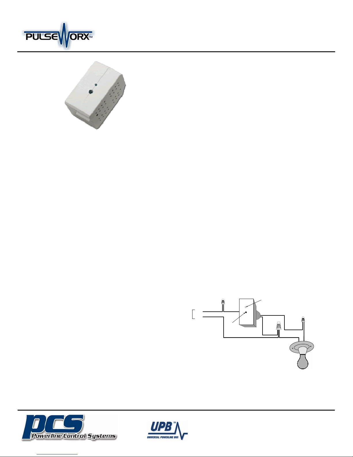
INSTALLATION
The Fixture Module – Relay is designed for indoor use with
devices that are permanently wired into the home electrical
system. To install the FMR1 module:
1. Locate the device to be controlled. Note that the device
power rating must not exceed 20 amps.
2. Disconnect power at the circuit breaker.
3. Remove any existing ceiling or wall fixture hardware for the
device. Disconnect the black wire that supplies power to
the device.
4. Using a wire nut, connect the black (Line) wire of the
fixture module to the black (Line) power wire.
5. Using a wire nut, connect the red (load output) wire of the
fixture module to the black wire from the lighting fixture or
device being controlled.
6. Using a large wire nut, connect the white (Neutral) wire of
the fixture module to the white (Neutral) power wire and
the white wire from the lighting fixture.
7. Refer to instructions on CONFUGRATION and OPERATION
prior to placing the fixture module in its final location, as it
may be necessary to have access to the Program Switch in
order to add the module to the UPB network and test its
operation. Temporarily restore power in order to perform
these functions. Disconnect power again when finished.
8. Once proper operation is established, fit the module into
the outlet box or otherwise secure it using wire ties or
fitting the nipple into a ½” knockout. Reinstall fixture
hardware as needed.
CAUTION: Do not insert metal objects into the module while it is
connected to power.
Status
LED
120VAC
POWER
LINE
NEUT
BLK
WHT
BLK
Program
Button
RED
WHT
Fixture
The Inventors Of:
19201 Parthenia St. Suite J
Northridge, CA 91324
(Phone) 818-701-9831 (Fax) 818-701-1506
sales@pcslighting.com www.pcslighting.com

Model: FMR1
Installation Guide and
Fixture Module - Relay
CONFIGURATION
Once your FMR1 is installed it can be configured either
manually or with the UPStart Setup Software.
Manual configuration can be used to add your FMR1 device
into a UPB network and link it to controller buttons. Refer to
the Keypad Controller’s Manual Configuration Guide
available on the PulseWorx website (www.PulseWorx.com)
for more details.
Although the factory default operation of the FMR1 is useful
in many situations, it is highly recommended that your device
be configured with UPStart Setup Software so that you can
take advantage of its many configurable features.
PCS has developed a Powerline Interface Module (PIM) and
free UPB Setup Tool software (UPStart) to help you configure
all of your PulseWorx Lighting System devices. User’s Guides
are available on the PulseWorx web site:
www.PulseWorx.com to explain how to configure your
system.
SETUP Mode
When configuring a UPB system, it will be necessary to place
the FMR1 in SETUP mode. To do this, press the Program
Button (see illustration) five times rapidly using a nonmetallic toothpick. The Status LED will continuously blink
Blue when the device is in SETUP mode. To exit SETUP mode,
press the Program Button once or wait five minutes for it to
time out.
OPERATION
The Fixture Module operates according to commands sent by
one or more UPB controllers. The FMR1 can accept powerline
commands from any UPB-compatible transmitter such as
PulseWorx Keypad Controllers, Timed Event Controllers, Wall
Switches, Interface Modules, approved Third-Party
Controllers and touch screens. The FMR1 can be a member of
up to 16 scenes with the capability to store a pre-set relay
state (on, off, or blink) for each scene.
Owner’s Manual
TEST Mode
A manual test feature allows the device to be turned ON and OFF
locally. To enable the TEST mode press and hold the Program
Button on the FMR1 for at least three seconds. The Status
LED will blink Magenta to indicate TEST mode. The fixture can
now be turned ON and OFF by single-tapping the Program
Button. Press and hold the Program Button again for at least
three seconds to exit from TEST mode.
Factory Default Settings
To restore the following default settings put the FMR1 into
SETUP mode and then press the Program Button ten times
rapidly. The Status LED will blink red to indicate that factory
defaults have been restored. Press the Program Button twice
more to stop the blinking.
Network ID:
Unit ID:
Network Password:
Receive Components:
Link #2 = OFF
Link #8 = Blink @ .5 sec
TYPICAL USES
The FMR1 is perfect for controlling 120VAC non-dimming loads
such as:
• Fans,
• Pumps,
• Low voltage transformers,
• Coffee makers,
• Christmas lights.
LIMITED WARRANTY
Seller warrants this product, if used in accordance with all
applicable instructions, to be free from original defects in
materials and workmanship for a period of five years from the
date of purchase. Refer to the warranty information on the
PulseWorx website (www.PulseWorx.com) for exact details.
255
61
1234
Link #1 = ON
AUTO-OFF Timer
New for Generation 2 is the ability to set a maximum on time.
If you forget to shut the fixture off yourself the fixture module
will do it for you automatically. The FMR1 can be configured
to inform the rest of the network when it has automatically
turned the appliance off. This allows the FMR1 to remotely
control other devices or update feedback indicators such as
LEDs.
The Inventors Of:
19201 Parthenia St. Suite J
Northridge, CA 91324
(Phone) 818-701-9831 (Fax) 818-701-1506
sales@pcslighting.com www.pcslighting.com
 Loading...