

Page 1

www.pulse-audio.co.uk
STAGEPAR-108
(Black order code: STAGEPAR-108B)
(Polished order code: STAGEPAR-108S)
User Manual
Page 2

3
Index
1 Safety Instruction............................................................................................................5
2 Introduction .................................................................................................................... 6
2.1 Supported function modes ....................................................................................7
2.1.1 Modes which support DMX input or DMX output.... .......................................7
2.1.2 Stand alone modes................................ ...........................................................8
3 Overview ........................................................................................................................9
3.1 Back view...............................................................................................................9
3
.2 DMX operation....................................................................................................10
3.2.1 Building a serial chain ...................................................................................10
3.2.2 LED PAR operates as a DMX master ............................................................10
3.2.3 LED PAR operates as a DMX slave ..............................................................10
4 Function Selection ........................................................................................................11
5 Auto change mode ........................................................................................................12
5.1 Mode setting ........................................................................................................12
5
.2 Speed setting........................................................................................................12
5.3 Colour pattern setting.........................................................................................13
6 Auto fade mode .. ..........................................................................................................14
6.1 Mode setting ........................................................................................................14
6.2 Fade speed ...........................................................................................................14
6.3 Colour pattern setting.........................................................................................15
7 Manual mode.........................................
.......................................................................16
7.1 Mode setting ........................................................................................................16
7.2 Colour pattern setting.........................................................................................17
7.2.1 Red Colour....................................................................................................17
7.2.2 Green Colour.................................................................................................17
7.2.3 Blue Colour....................... ............................................................................18
8 DMX slave 5ch mode ................................................................................................
...19
8.1 Mode setting ........................................................................................................19
8.2 Speed setting........................................................................................................19
8.3 DMX usage for 5ch control.................................................................................20
8.4 Set up of the first DMX receiving channel ............................. ............................21
8.5 Examples .............................................................................................................22
8.5.1 Example A, first DMX receive channel is 1 ...................................................22
8.5.2 Example B, first DMX receive channel is 22 .................................................22
8.5.
3 Example C, first DMX receive channel is 272 ...............................................22
8.5.4 Example D, first DMX receive channel is 508 ...............................................22
9 DMX master 5ch mode.................................... .............................................................23
9.1 Mode setting ........................................................................................................23
Page 3

4
9.2 Speed setting........................................................................................................23
9.3 DMX usage for 5ch control.................................................................................24
9.4 Colour pattern setting.........................................................................................25
9.4.1 Colour patterns..............................................................................................25
9.4.2 Fading in out colour patterns .........................................................................25
9.4.3 Fading over colour patterns ...........................................................................26
9.4.4 Chaser colour patterns ...................................................................................26
9.
5 Examples .............................................................................................................28
9.5.1 Example A ....................................................................................................28
9.5.2 Example B.....................................................................................................29
10 DMX slave 3ch .........................................................................................................31
10.1 Mode setting ........................................................................................................31
10.2 DMX usage .................................... ......................................................................31
10.3 Set up of the first DMX receiving channel ...............
..........................................32
10.4 Examples .............................................................................................................33
10.4.1 Example A, first DMX receive channel is 1 ...................................................33
10.4.2 Example B, first DMX receive channel is 22 .................................................33
10.4.3 Example C, first DMX receive channel is 272 ...............................................33
10.4.4 Example D, first DMX receive channel is 510 ...............................................33
11 DMX master 3ch.......................................................................................................34
11.1 Mode setting .................................................................................
.......................34
11.2 Speed setting........................................................................................................34
11.3 DMX usage for 3ch control.................................................................................34
11.4 Colour pattern setting.........................................................................................35
11.5 Examples .............................................................................................................36
11.5.1 Example A ..... ...............................................................................................36
11.5.2 Example B........... ..........................................................................................37
12 Technical Specifications ................................................
...........................................38
36 LEDs, 3W................................................................................................. 38
...........................
Page 4

5
1 Safety Instruction
Keep this device away from rain and moisture!
Unplug mains lead before opening the housing!
Never look directly into the light source (sensitive persons may suffer an epileptic
shock).
Never leave this device running unattended.
Keep away children.
When installing the device, make sure there is no highly inflammable material within
a distance of 0.5m.
Page 5

6
2 Introduction
Main feature of this LED PAR is, that it can be used as a 4ch DMX controller.
In this mode 4 LED PARs are connected with XLR cables on their DMX In-/Outputs.
The first LED PAR is set to DMX master mode. Now the LED PAR in master mode sent
control signals to the connected slaves. There are different patterns available e.g. all
connected LED PARs do the same, each shows different patterns, chaser programs, fade in –
fade out patterns and fade over patterns. The steps of the patterns can be controlled by music
beat or by a potentiometer. The music sensitivity is controllable. The colour patterns offers a
100% colour mode, a 100% / 50% colour mode, and a 100% / 75% / 50% /25% colour mode.
The colours are shown by random.
A 3ch DMX slave mode is supported, for easy connection in a DMX syste m. All 512channels
are supported.
Stand alone modes colour change, fading patterns and fixed colour settings are supported.
Page 6

7
2.1 Supported function modes
2.1.1 Modes which support DMX input or DMX output
2.1.1.1 5 channel master mode
In this mode the LED PAR is used as a 4 channel DMX master.
The 5channel master mode is offered to be compatible to the first revision of the LED PAR.
The 5channel master mode uses build in functions of the LED PARs. Which will be
controlled by the DMX signal.
There are different patterns available e.g. all connected LED PARs do the same, each shows
different patterns, chaser programs, fade in – fade out patterns and fade over patterns. The
steps of the patterns can be controlled by music beat or by a potentiometer. The music
sensitivity is controllable. The colour patterns offers a 100% colour mode, a 100% / 50%
colour mode, and a 100% / 75% / 50% /25% colour mode. The colours are shown by random.
2.1.1.2 3 channel master mode
In this mode the LED PAR is used as a 4 channel DMX master.
The 3channel master mode is offered for less consumption of DMX channels e.g. in case of
connected DMX power packs or other DMX receivers.
There are different patterns available e.g. all connected LED PARs do the same, each shows
different patterns, chaser programs, fade in – fade out patterns and fade over patterns. The
steps of the patterns can be controlled by music beat or by a potentiometer. The music
sensitivity is controllable. The colour patterns offers a 100% colour mode, a 100% / 50%
colour mode, and a 100% / 75% / 50% /25% colour mode. The colours are shown by random.
2.1.1.3 5 channel slave mode
In this mode the LED PAR is used as a DMX slave.
The 5channel slave mode is supported if the LED PAR is in use with the first revision of the
LED PAR. The 5channel slave mode uses build in functions, which be controlled by the
DMX signal. An external DMX controller controls the Led PAR.
2.1.1.4 3 channel slave mode
The 3channel slave mode is for use with a standard DMX controller. The LED PAR can be
controller with all 512 channels. Each colour is controlled by one DMX channel. All 512
DMX channels can be used.
Page 7

8
2.1.2 Stand alone modes
2.1.2.1 Auto fade mode
There is an auto fade mode available with different fade in/fade out patterns and fade over
patterns. Even here a compatible mode is offered for use with the first revision of the LED
PAR. The fade in/fade out and fade over time can be set accurate by 9 time settings.
The auto fade mode supports different colour change patterns:
The colour patterns offers a 100% colour mode, a 100% / 50% colour mode, and a 100% /
75% / 50% /25% colour mode. The colours are shown by random.
The compatible mode is for use with the first revision of the LED PAR
2.1.2.2 Auto change mode
The auto change mode supports different colour change patterns.
The colour patterns offers a 100% colour mode, a 100% / 50% colour mode, and a 100% /
75% / 50% /25% colour mode. The colours are shown by random.
The compatible mode is for use with the first revision of the LED PAR
The change speed can be controlled by music or potentiometer.
2.1.2.3 manual mode
In the manual mode each colour can be set to on in steps of ~14%.
Page 8

9
3 Overview
3.1 Back view
This picture shows the backside of the LED PAR.
DMX-Input:
In case of external DMX control, the DMX cable is connected here.
DMX-Input pin Signal
1 Ground
2 Signal “-”
3 Signal “+”
DMX-Output:
Connect here the DMX cable for next unit.
DMX-Output pin Signal
1 Ground
2 Signal “-”
3 Signal “+”
Function:
This 4 pin dipswitch sets, the function mode of the LED PAR.
Pattern:
The function of this 10 pin dipswitch depend on the selected mode, e.g. in chaser mode the
chaser patterns are selected here.
Speed:
Manual speed setting.
Music:
Sensitivity control for the build in microphone.
Page 9

10
3.2 DMX operation
3.2.1 Building a serial chain
Connect the DMX-output of the first unit in the DMX-chain with the DMX-input of the next
fixture. Always connect one output with the input of the next unit until all fixtures are
connected.
The last unit of the DMX chain has to be terminated with a resistor. Connect a 120 Ohm
resistor between Signal “-“ and Signal “+” to DMX-output-socket of the last unit .
3.2.2 LED PAR operates as a DMX master
In the DMX master mode, the LED operates as a DMX controller to the connected units in the
DMX chain.
If the LED PAR is used as a DMX master, it must be the first unit in the DMX chain. Unplug
the DMX input cable of the LED PAR which operates as a DMX master.
3.2.3 LED PAR operates as a DMX slave
In the DMX slave mode the LED PAR operates as a normal DMX receiver. It is controlled by
an external DMX controller.
Page 10
11
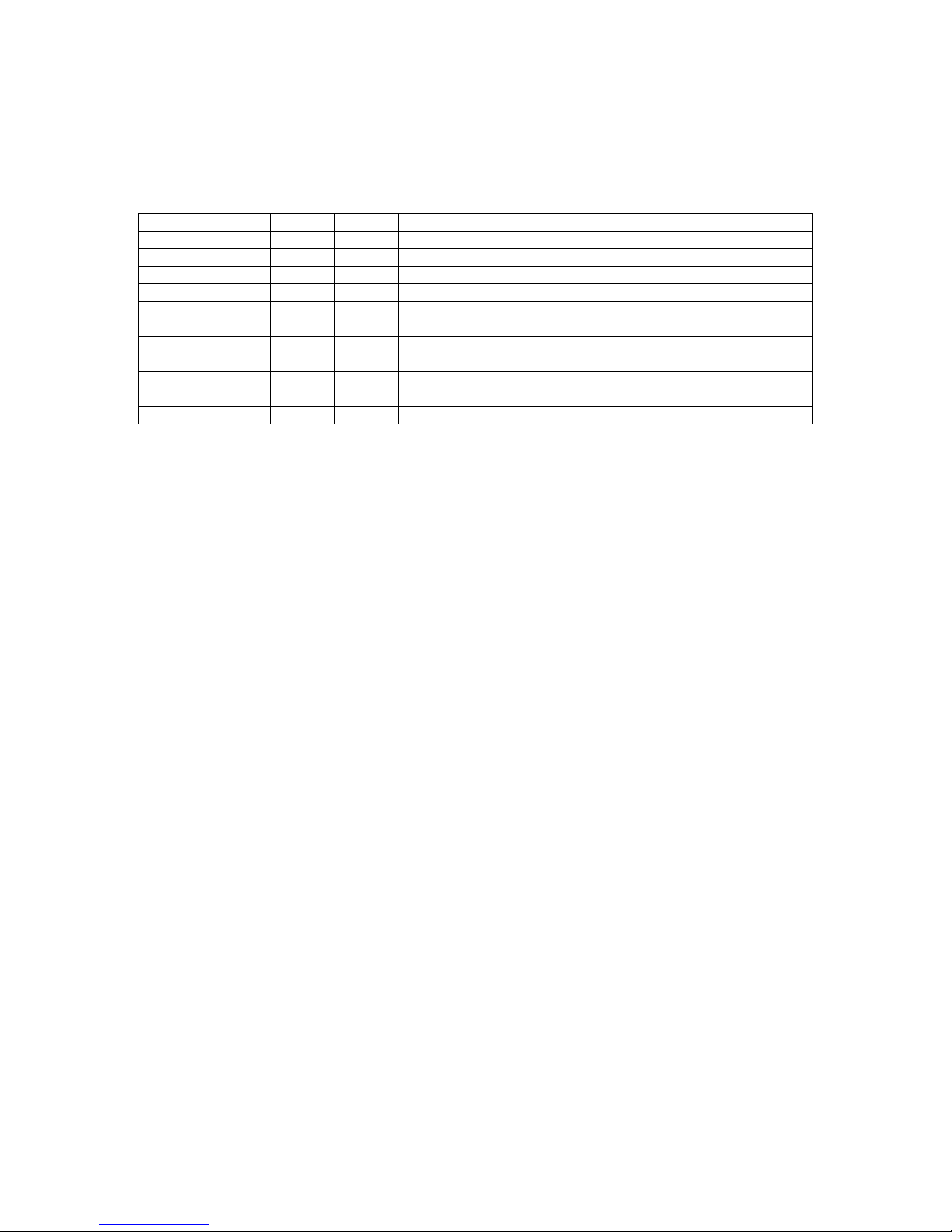
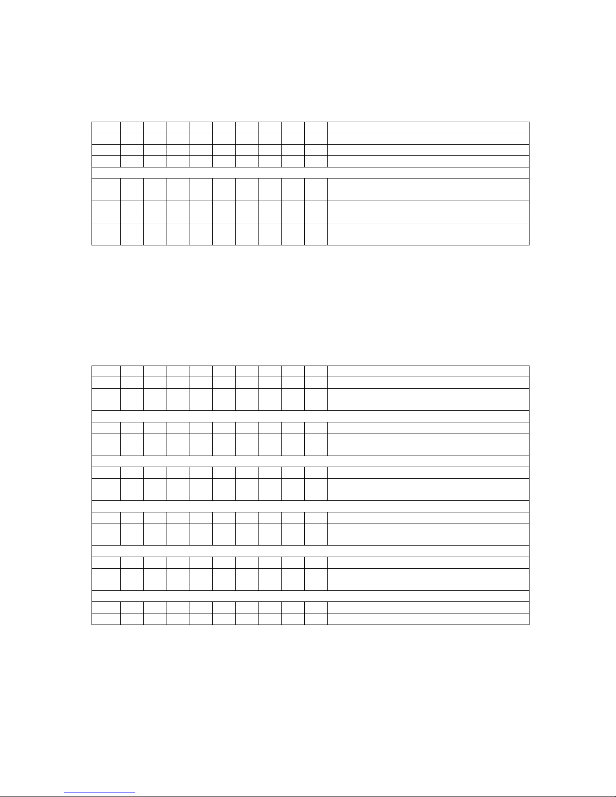
4 Function Selection
The LED PAR modes may be set by the 4pin dipswitch on the backside of the LED PAR
according to the this table:
SW4 SW3 SW2 SW1 mode
X 0 0 0 auto change
X 0 0 1 auto fade
X 0 1 0 manual mode
X 0 1 1 DMX slave 5ch
X 1 0 0 DMX master 5ch
X 1 0 1 DMX slave 3ch
X 1 1 0 DMX master 3ch
X 1 1 1 No new mode (DMX master 3ch is used)
0 X X X speed control by potentiometer, if selected mode support it
1 X X X speed control by music, if selected mode support it
0 = dipswitch is set to off
1 = dipswitch is set to on
X = see information below/above
Page 11
12
5 Auto change mode
The LED PAR shows different colours depending on speed selection.
In this mode the LED PAR is used stand alone, the DMX output/input is not used.
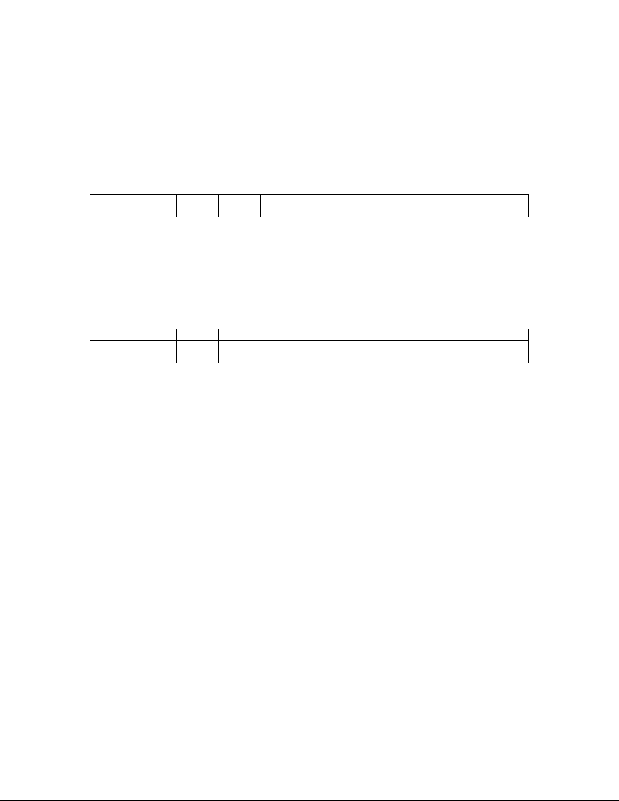
5.1 Mode setting
To enable the auto change mode, set the 4 pin dipswitch on the backside of the LED PAR
according to the this table:
SW4 SW3 SW2 SW1 Mode
X 0 0 0 auto change
0 = dipswitch is set to off
1 = dipswitch is set to on
X = see information below
5.2 Speed setting
SW4 setup the speed source. Choose the speed source according this table
SW4 SW3 SW2 SW1 mode
0 X X X speed control by potentiometer
1 X X X speed control by music
0 = dipswitch is set to off
1 = dipswitch is set to on
X = see information above
Page 12

13
5.3 Colour pattern setting
The colour modes may be set by the 10pin dipswitch on the backside of the LED PAR
according to the this table:
SW10 SW9 SW8 SW7 SW6 SW5 SW4 SW3 SW2 SW1 Colour pattern selection
0 0 0 0 0 0 0 0 0 0 compatible mode - old pattern style
0 0 0 0 0 0 0 0 0 1 100% colour change
0 0 0 0 0 0 0 0 1 0 100%, 50% colour change
0 0 0 0 0 0 0 0 1 1 100%, 75%, 50%, 25% colour change
0 = dipswitch is set to off
1 = dipswitch is set to on
If another colour pattern is set, always patterns “0000000011” is used.
Page 13

14
6 Auto fade mode
The LED PAR shows different fading colours depending on speed selection.
In this mode the LED PAR is used stand alone, the DMX output/input is not used.
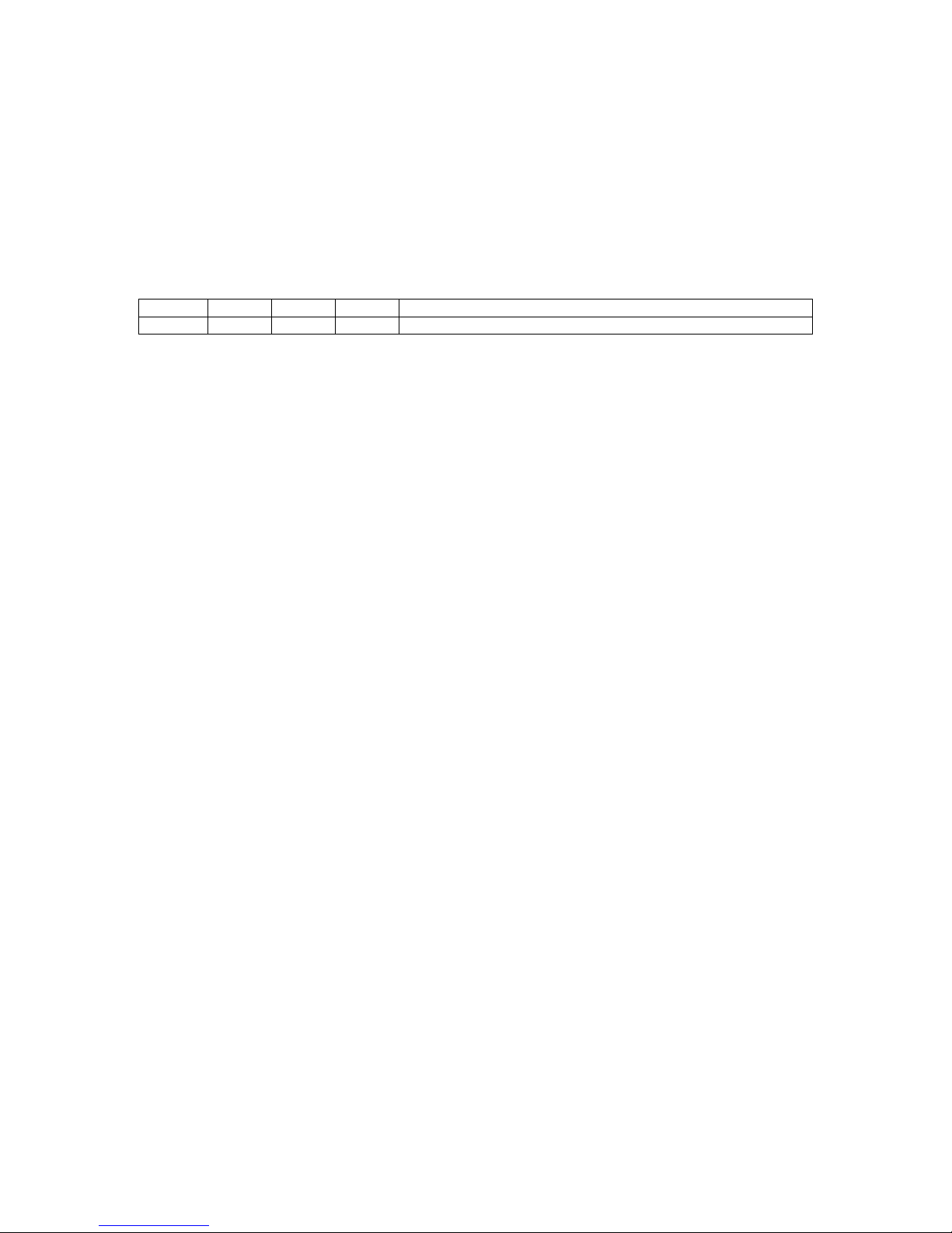
6.1 Mode setting
To enable the auto change mode, set the 4pin dipswitch on the backside of the LED PAR
according to the this table:
SW4 SW3 SW2 SW1 mode
X 0 0 1 auto fade
0 = dipswitch is set to off.
1 = dipswitch is set to on.
X = in this mode there is no speed control by potentiometer or music supported
6.2 Fade speed
The fading speed may be set by the 10pin dipswitch on the backside of the LED PAR
according to the this table:
SW10 SW9 SW8 SW7 SW6 SW5 SW4 SW3 SW2 SW1 Fading speed selection
0 0 0 X X X 0 0 0 0 10:30min
0 0 0 X X X 0 0 0 1 2,5s
0 0 0 X X X 0 0 1 0 5s
0 0 0 X X X 0 0 1 1 10s
0 0 0 X X X 0 1 0 0 20s
0 0 0 X X X 0 1 0 1 40s
0 0 0 X X X 0 1 1 0 80s
0 0 0 X X X 0 1 1 1 160s
0 0 0 X X X 1 0 0 0 320s
0 = dipswitch is set to off.
1 = dipswitch is set to on.
X = see table below
If another timing pattern is set, always patterns “000xxx1000” is used.
No speed control by potentiometer or music is supported in this mode.
Page 14

15
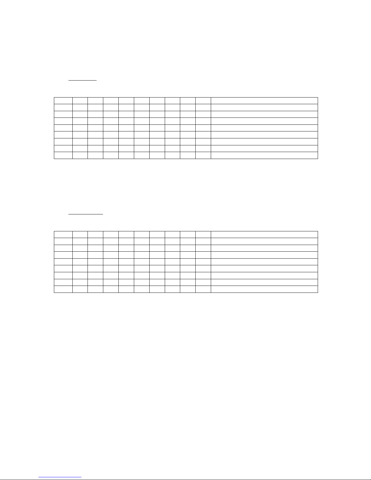
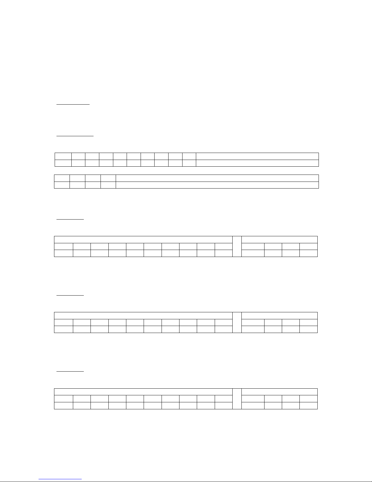
6.3 Colour pattern setting
The fading patterns may be set by the 10pin dipswitch on the backside of the LED PAR
according to the this table:
SW10 SW9 SW8 SW7 SW6 SW5 SW4 SW3 SW2 SW1 Colour pattern selection
0 0 0 0 0 0 X X X X compatible mode - old pattern style
0 0 0 0 0 1 X X X X 100% colour change, fade in and out
0 0 0 0 1 0 X X X X 100%, 50% colour change, fade in and out
0 0 0 0 1 1 X X X X 100%, 75%, 50%, 25% colour change, fade in
and out
0 0 0 1 0 0 X X X X 100% colour change, fade in
0 0 0 1 0 1 X X X X 100%, 50% colour change, fade in
0 0 0 1 1 0 X X X X 100%, 75%, 50%, 25% colour change, fade in
0 = dipswitch is set to off.
1 = dipswitch is set to on.
X = see table above
If another colour pattern is set, always pattern 000110xxxx is used.
Page 15
16
7 Manual mode
The LED PAR shows different fixed colours.
In this mode the LED PAR is used stand alone, the DMX output/input is not used.
7.1 Mode setting
To enable the manual mode, set the 4pin dipswitch on the backside of the LED PAR
according to the this table:
SW4 SW3 SW2 SW1 mode
X 0 1 0 manual mode
0 = dipswitch is set to off
1 = dipswitch is set to on
X = in this mode there is no speed control by potentiometer or music supported
Page 16
17
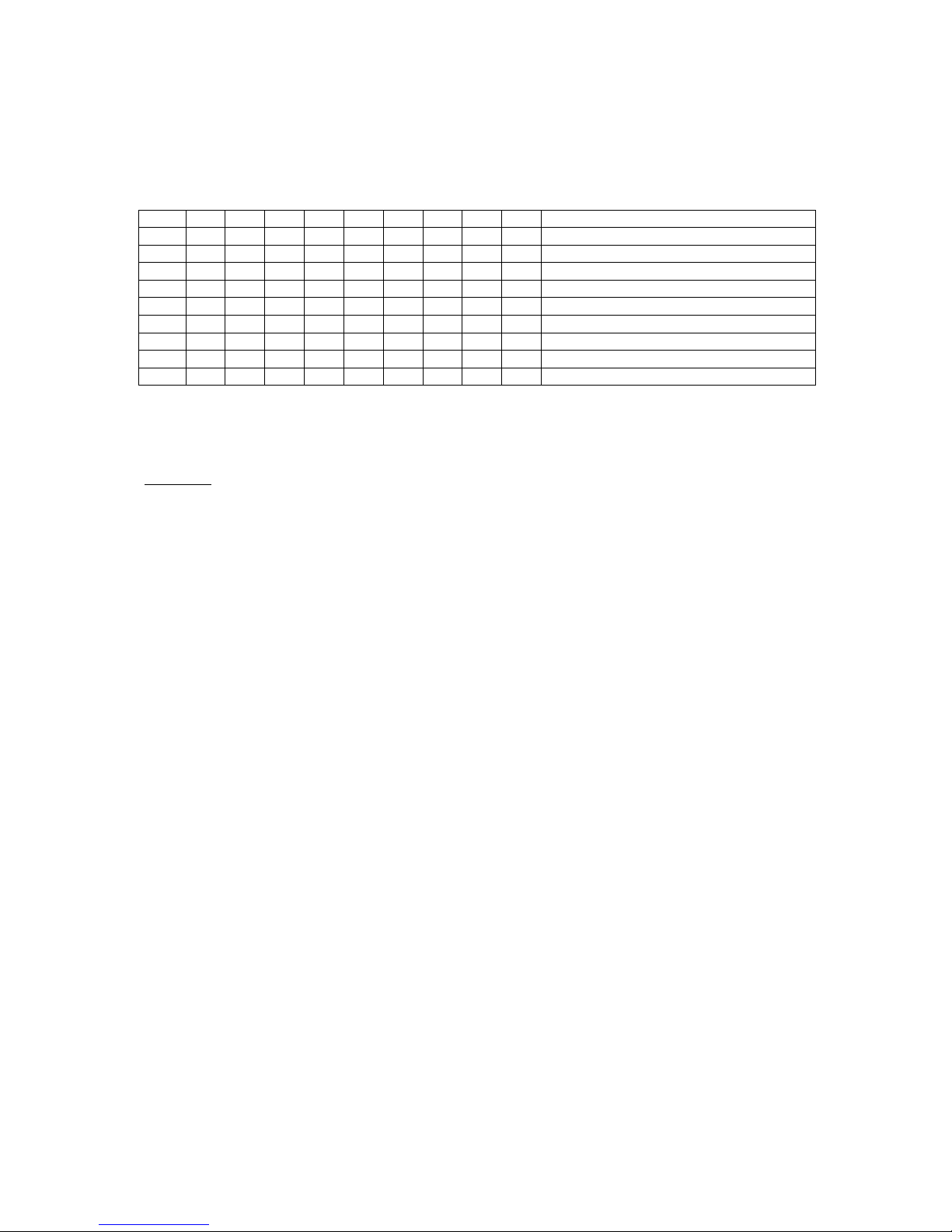
7.2 Colour pattern setting
7.2.1 Red Colour
The red colour may be set by the 10pin dipswitch on the backside of the LED PAR according
to the this table:
SW10 SW9 SW8 SW7 SW6 SW5 SW4 SW3 SW2 SW1 Red colour brightness
0 X X X X X X 0 0 0 0%
0 X X X X X X 0 0 1 14%
0 X X X X X X 0 1 0 28%
0 X X X X X X 0 1 1 42%
0 X X X X X X 1 0 0 57%
0 X X X X X X 1 0 1 71%
0 X X X X X X 1 1 0 85%
0 X X X X X X 1 1 1 100%
0 = dipswitch is set to off
1 = dipswitch is set to on
X = see table below
7.2.2 Green Colour
The green colour may be set by the 10pin dipswitch on the backside of the LED PAR
according to the following table:
SW10 SW9 SW8 SW7 SW6 SW5 SW4 SW3 SW2 SW1 Green colour brightness
0 X X X 0 0 0 X X X 0%
0 X X X 0 0 1 X X X 14%
0 X X X 0 1 0 X X X 28%
0 X X X 0 1 1 X X X 42%
0 X X X 1 0 0 X X X 57%
0 X X X 1 0 1 X X X 71%
0 X X X 1 1 0 X X X 85%
0 X X X 1 1 1 X X X 100%
0 = dipswitch is set to off.
1 = dipswitch is set to on.
X = see table above or below
Page 17
18
7.2.3 Blue Colour
The blue colour may be set by the 10pin dipswitch on the backside of the LED PAR
according to the this table:
SW10 SW9 SW8 SW7 SW6 SW5 SW4 SW3 SW2 SW1 Blue colour brightness
0 0 0 0 X X X X X X 0%
0 0 0 1 X X X X X X 14%
0 0 1 0 X X X X X X 28%
0 0 1 1 X X X X X X 42%
0 1 0 0 X X X X X X 57%
0 1 0 1 X X X X X X 71%
0 1 1 0 X X X X X X 85%
0 1 1 1 X X X X X X 100%
0 = dipswitch is set to off.
1 = dipswitch is set to on.
X = see table above
Page 18

19
8 DMX slave 5ch mode
The item is controlled by 5 DMX channels according the table below.
With Dipswitch 1 to 9 the first DMX channel to receive is set.
8.1 Mode setting
To enable the DMX slave 5ch mode, set the 4pin dipswitch on the backside of the LED PAR
according to the this table:
SW4 SW3 SW2 SW1 mode
X 0 1 1 DMX slave 5ch
0 = dipswitch is set to off
1 = dipswitch is set to on
X = see information below
8.2 Speed setting
SW4 setup the speed source. Choose the speed source according this table
SW4 SW3 SW2 SW1 mode
0 X X X speed control by potentiometer, if selected function support it
1 X X X speed control by music, if selected mode support it
0 = dipswitch is set to off
1 = dipswitch is set to on
X = see information above
Page 19
20
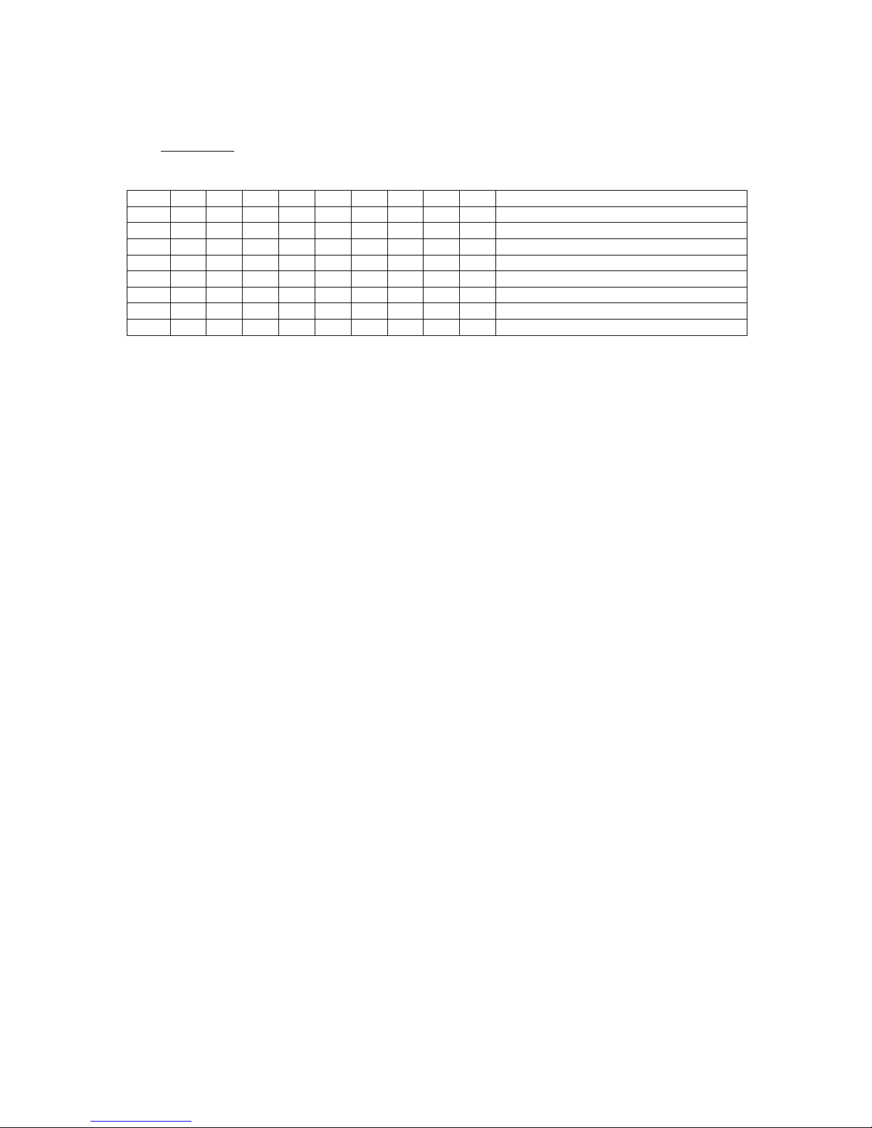
8.3 DMX usage for 5ch control
The table shows the DMX value which need to be sent to the LED PAR by an external DMX
controller:
Channel 1 value Function
0 - 63 RGB control, CH2 = red, CH3 = green, CH4 = blue
64 – 127 7 colour fade, CH5 = speed control
128 – 191 7 colour change, CH5 = speed control
192 – 255 3 colour change, CH5 = speed control
Channel 2 value Function
0 – 255 Red colour 0% – 100%
Channel 3 value Function
0 – 255 Green colour 0% – 100%
Channel 4 value Function
0 – 255 Blue colour 0% – 100%
Channel 5 value Function
0 - 10 no function – no speed
11 - 100 value 11 to 100, fast speed to low speed
101 - 150 no function – no speed
151 - 255 speed control by unit, by music or potentiometer
Page 20

21
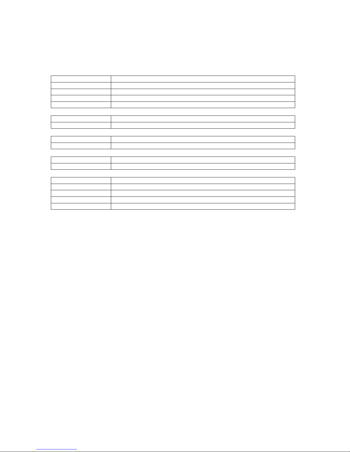
8.4 Set up of the first DMX receiving channel
The value of dipswitch 1 to 9 is binary coded. To set a wished DMX receiving channel add
the different values (see example below of the table):
SW10 SW9 SW8 SW7 SW6 SW5 SW4 SW3 SW2 SW1 First DMX receive channel
0 0 0 0 0 0 0 0 0 1 1
0 0 0 0 0 0 0 0 1 0 2
0 0 0 0 0 0 0 1 0 0 4
0 0 0 0 0 0 1 0 0 0 8
0 0 0 0 0 1 0 0 0 0 16
0 0 0 0 1 0 0 0 0 0 32
0 0 0 1 0 0 0 0 0 0 64
0 0 1 0 0 0 0 0 0 0 128
0 1 0 0 0 0 0 0 0 0 256
0 = dipswitch is set to off.
1 = dipswitch is set to on.
Remarks:
In case of all dipswitches 1 to 9 are set to zero, the first DMX receive channel is 1.
I case of only dipswitch 1 is set to on, the first DMX receive channel is 1.
The maximum first receive channel is channel 508.
In case of chosen first receive channel bigger than 508, the maximum receive channel is still
508.
Page 21

22
8.5 Examples
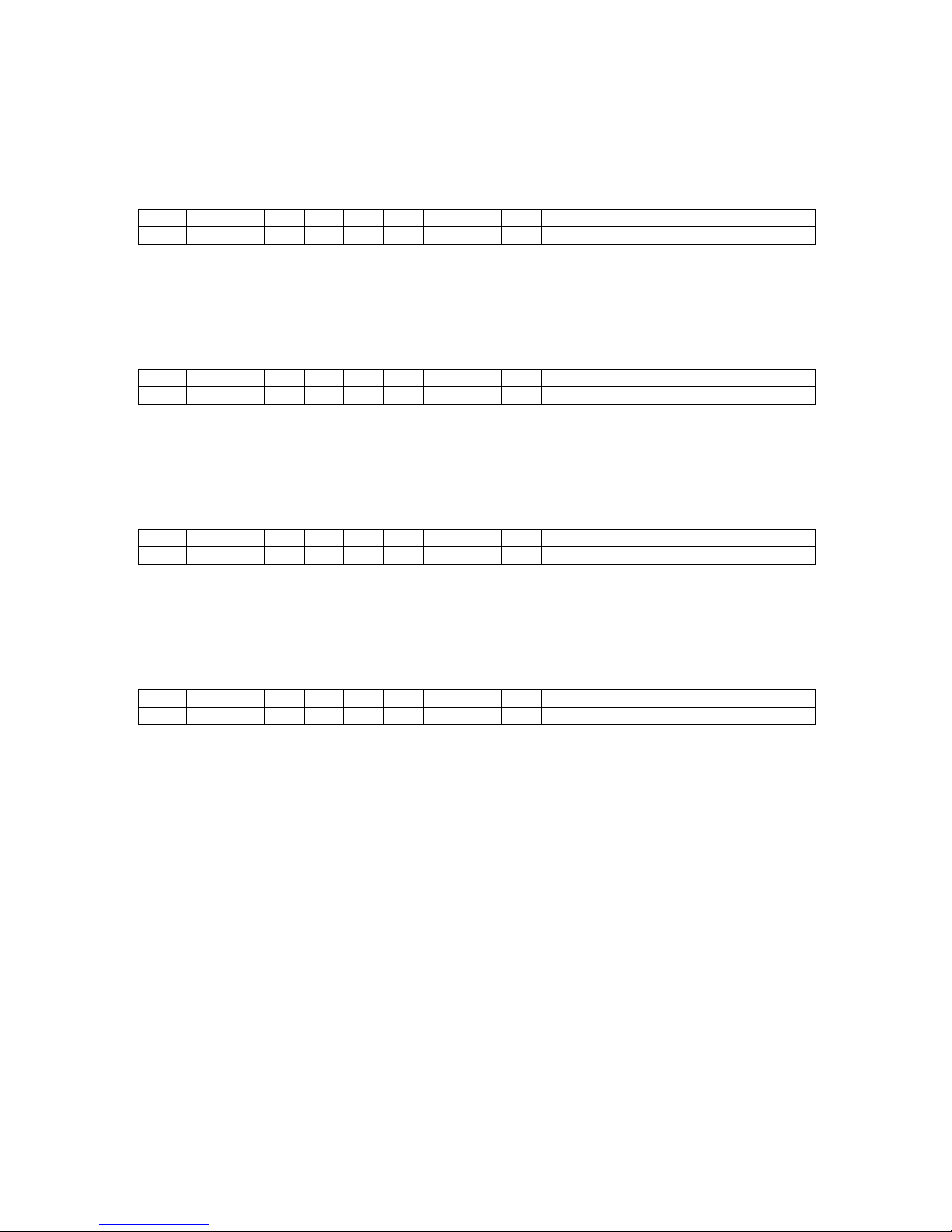
8.5.1 Example A, first DMX receive channel is 1
SW10 SW9 SW8 SW7 SW6 SW5 SW4 SW3 SW2 SW1 First DMX receive channel
0 0 0 0 0 0 0 0 0 1 1
The item start to receive with the DMX CH1.
The items consumes CH1, CH2, CH3, CH4, CH5.
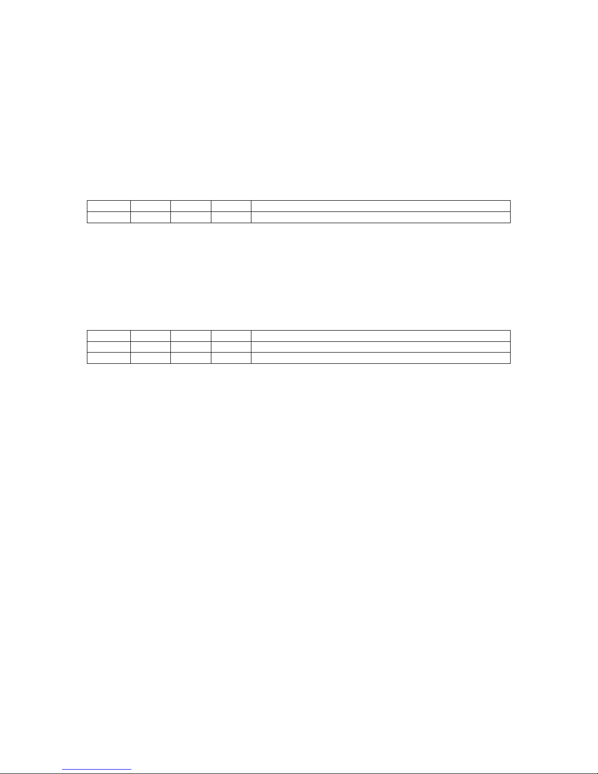
8.5.2 Example B, first DMX receive channel is 22
SW10 SW9 SW8 SW7 SW6 SW5 SW4 SW3 SW2 SW1 First DMX receive channel
0 0 0 0 0 1 0 1 1 0 22
The item start to receive with the DMX CH22.
The items consumes CH22, CH23, CH24, CH25, CH26.
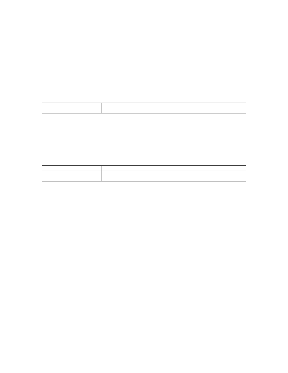
8.5.3 Example C, first DMX receive channel is 272
SW10 SW9 SW8 SW7 SW6 SW5 SW4 SW3 SW2 SW1 First DMX receive channel
0 1 0 0 0 1 0 0 0 0 272
The item start to receive with the DMX CH272.
The items consumes CH272, CH273, CH274, CH275, CH276.
8.5.4 Example D, first DMX receive channel is 508
SW10 SW9 SW8 SW7 SW6 SW5 SW4 SW3 SW2 SW1 First DMX receive channel
0 1 1 1 1 1 1 1 0 0 508
The item start to receive with the DMX CH508.
The items consumes CH508, CH509, CH510, CH511, CH512.
Page 22
23
9 DMX master 5ch mode
In this mode the LED PAR is a DMX controller in 5ch mode. The 5ch mode is build in for
controlling the new revision and old revision of the LED PAR. The connected slaves need to
be set to a 5ch DMX slave (see chapter 8.3).
9.1 Mode setting
To enable the DMX master 5ch mode, set the 4pin dipswitch on the backside of the LED PAR
according to the this table:
SW4 SW3 SW2 SW1 mode
X 1 0 0 DMX master 5ch
0 = dipswitch is set to off
1 = dipswitch is set to on
X = see information below
9.2 Speed setting
SW4 setup the speed source. Choose the speed source according this table
SW4 SW3 SW2 SW1 mode
0 X X X speed control by potentiometer
1 X X X speed control by music
0 = dipswitch is set to off
1 = dipswitch is set to on
X = see information above
Page 23

24
9.3 DMX usage for 5ch control
The LED PAR in master mode sent DMX data accor ding to the table below. The connected
slaves need to be set up to a 5channel salve (see chapter 8.3).
1. DMX CH = 0, RGB control
2. DMX CH = RED
3. DMX CH = GREEN
4. DMX CH = BLUE
5. DMX CH = 0, no function, no speed
6. DMX CH = 0, RGB control
7. DMX CH = RED
8. DMX CH = GREEN
9. DMX CH = BLUE
10. DMX CH = 0, no function, no speed
11. DMX CH = 0, RGB control
12. DMX CH = RED
13. DMX CH = GREEN
14. DMX CH = BLUE
15. DMX CH = 0, no function, no speed
16. DMX CH = 0, RGB control
17. DMX CH = RED
18. DMX CH = GREEN
19. DMX CH = BLUE
20. DMX CH = 0, no function, no speed
Page 24
25
9.4 Colour pattern setting
The colour patterns may be set by the 10pin dipswitch on the backside of the LED PAR
according to the following tables:
9.4.1 Colour patterns
All LED PARs are on and changing colours.
SW10 SW9 SW8 SW7 SW6 SW5 SW4 SW3 SW2 SW1 Colour pattern selection
0 0 0 0 0 0 0 0 0 0 4ch, Pattern 1, all on, all do the same
0 0 0 0 0 0 0 0 0 1 4ch, Pattern 2, all on, all do the same
0 0 0 0 0 0 0 0 1 0 4ch, Pattern 3, all on, all do the same
0 0 0 0 0 0 0 0 1 1 4ch, Pattern 1, all on, every unit has his own pattern
0 0 0 0 0 0 0 1 0 0 4ch, Pattern 2, all on, every unit has his own pattern
0 0 0 0 0 0 0 1 0 1 4ch, Pattern 3, all on, every unit has his own pattern
0 = dipswitch is set to off.
1 = dipswitch is set to on.
9.4.2 Fading in out colour patterns
The colour is fading in and out.
SW10 SW9 SW8 SW7 SW6 SW5 SW4 SW3 SW2 SW1 Colour pattern selection
0 0 0 0 0 0 0 1 1 0 4ch, Pattern 1, all on, all do the same, with fade in
and out
0 0 0 0 0 0 0 1 1 1 4ch, Pattern 2, all on, all do the same, with fade in
and out
0 0 0 0 0 0 1 0 0 0 4ch, Pattern 3, all on, all do the same, with fade in
and out
0 0 0 0 0 0 1 0 0 1 4ch, Pattern 1, every unit has his own pattern, with
fade in and out
0 0 0 0 0 0 1 0 1 0 4ch, Pattern 2, every unit has his own pattern, with
fade in and out
0 0 0 0 0 0 1 0 1 1 4ch, Pattern 3, every unit has his own pattern, with
fade in and out
0 = dipswitch is set to off.
1 = dipswitch is set to on.
Page 25
26
9.4.3 Fading over colour patterns
The colour is fading over.
SW10 SW9 SW8 SW7 SW6 SW5 SW4 SW3 SW2 SW1 Colour pattern selection
0 0 0 0 0 0 1 1 0 0 4ch, Pattern 1, all on, all do the same, with fade over
0 0 0 0 0 0 1 1 0 1 4ch, Pattern 2, all on, all do the same, with fade over
0 0 0 0 0 0 1 1 1 0 4ch, Pattern 3, all on, all do the same, with fade over
0 0 0 0 0 0 1 1 1 1 4ch, Pattern 1, every unit has his own pattern, with
fade over
0 0 0 0 0 1 0 0 0 0 4ch, Pattern 2, every unit has his own pattern, with
fade over
0 0 0 0 0 1 0 0 0 1 4ch, Pattern 3, every unit has his own pattern, with
fade over
0 = dipswitch is set to off.
1 = dipswitch is set to on.
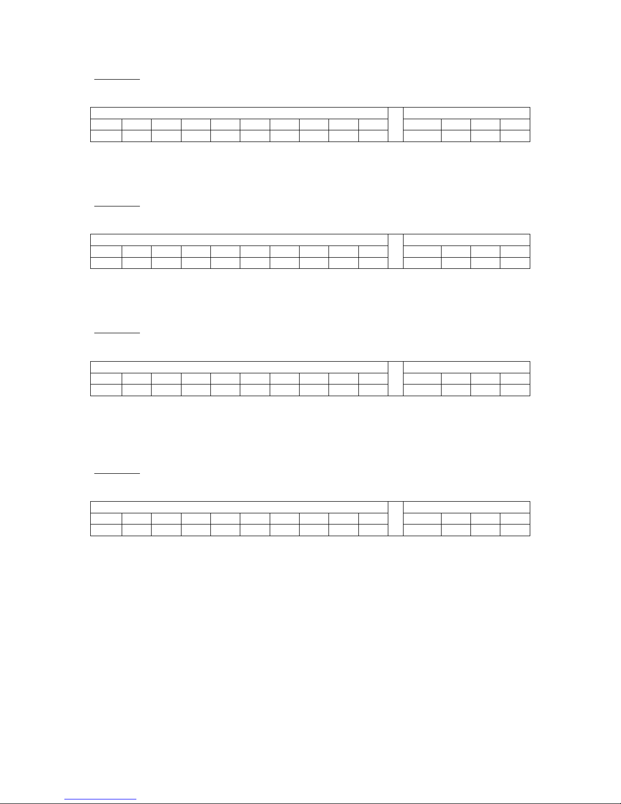
9.4.4 Chaser colour patterns
9.4.4.1 One LED PAR of four is on
SW10 SW9 SW8 SW7 SW6 SW5 SW4 SW3 SW2 SW1 Colour pattern selection
0 0 0 0 0 1 0 0 1 0 chaser pattern 1, right to left, same colour each step
0 0 0 0 0 1 0 0 1 1 chaser pattern 1, right to left – left to right, same
colour each step
0 0 0 0 0 1 0 1 0 0 chaser pattern 2, right to left, same colour each step
0 0 0 0 0 1 0 1 0 1 chaser pattern 2, right to left –left to right, same
colour each step
0 0 0 0 0 1 0 1 1 0 chaser pattern 3, right to left, same colour each step
0 0 0 0 0 1 0 1 1 1 chaser pattern 3, right to left –left to right, same
colour each step
0 0 0 0 0 1 1 0 0 0 chaser pattern 1, right to left, new colour each step
0 0 0 0 0 1 1 0 0 1 chaser pattern 1, right to left –left to right, new
colour each step
0 0 0 0 0 1 1 0 1 0 chaser pattern 2, right to left, new colour each step
0 0 0 0 0 1 1 0 1 1 chaser pattern 2, right to left –left to right, new
colour each step
0 0 0 0 0 1 1 1 0 0 chaser pattern 3, right to left, new colour each step
0 0 0 0 0 1 1 1 0 1 chaser pattern 3, right to left, new colour each step
0 = dipswitch is set to off.
1 = dipswitch is set to on.
Page 26

27
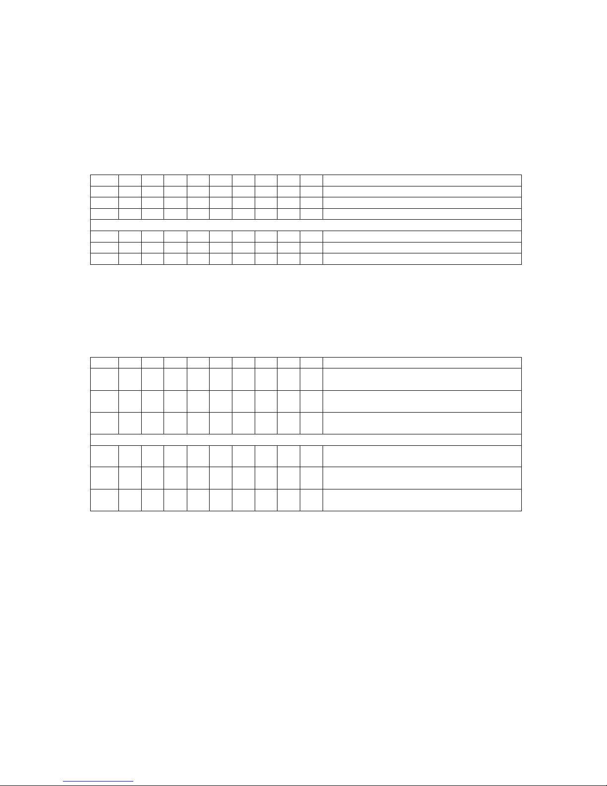
9.4.4.2 Two LED PAR of four is on
SW10 SW9 SW8 SW7 SW6 SW5 SW4 SW3 SW2 SW1 Colour pattern selection
0 0 0 0 0 1 1 1 1 0 chaser pattern 1, right to left, new colour
each step
0 0 0 0 0 1 1 1 1 1 chaser pattern 1, right to left – left to right,
new colour each step
0 0 0 0 1 0 0 0 0 0 chaser pattern 2, right to left, new colour
each step
0 0 0 0 1 0 0 0 0 1 chaser pattern 2, right to left – left to right,
new colour each step
0 0 0 0 1 0 0 0 1 0 chaser pattern 3, right to left, new colour
each step
0 0 0 0 1 0 0 0 1 1 chaser pattern 3, right to left – left to right,
new colour each step
0 0 0 0 1 0 0 1 0 0 chaser pattern 1, right to left, every unit has
his own pattern, new colour each step
0 0 0 0 1 0 0 1 0 1 chaser pattern 1, right to left – left to right,
every unit has his own pattern, new colour
each step
0 0 0 0 1 0 0 1 1 0 chaser pattern 2, right to left, every unit has
his own pattern, new colour each step
0 0 0 0 1 0 0 1 1 1 chaser pattern 2, right to left – left to right,
every unit has his own pattern, new colour
each step
0 0 0 0 1 0 1 0 0 0 chaser pattern 3, right to left, every unit has
his own pattern, new colour each step
0 0 0 0 1 0 1 0 0 1 chaser pattern 3, right to left – left to right,
every unit has his own pattern, new colour
each step
0 = dipswitch is set to off.
1 = dipswitch is set to on.
Page 27
28
9.5 Examples
9.5.1 Example A
This example shows how to set up four LED PARs to be controlled in 5ch DMX master
mode.
Connection:
MASTER SLAVE1 SLVAE2 SLAVE3
UNIT1 UNIT2 UNIT3 UNIT4
Master setup:
Master unit, UNIT1, need to be set by this table:
SW10 SW9 SW8 SW7 SW6 SW5 SW4 SW3 SW2 SW1 Colour pattern selection
0 0 0 0 0 1 0 0 1 0 chaser pattern 1, right to left, same colour each step
SW4 SW3 SW2 SW1 Mode
0 1 0 0 DMX master 5ch, speed control by potentiometer
The items consumes ch1, ch2, ch3, ch4, ch5.
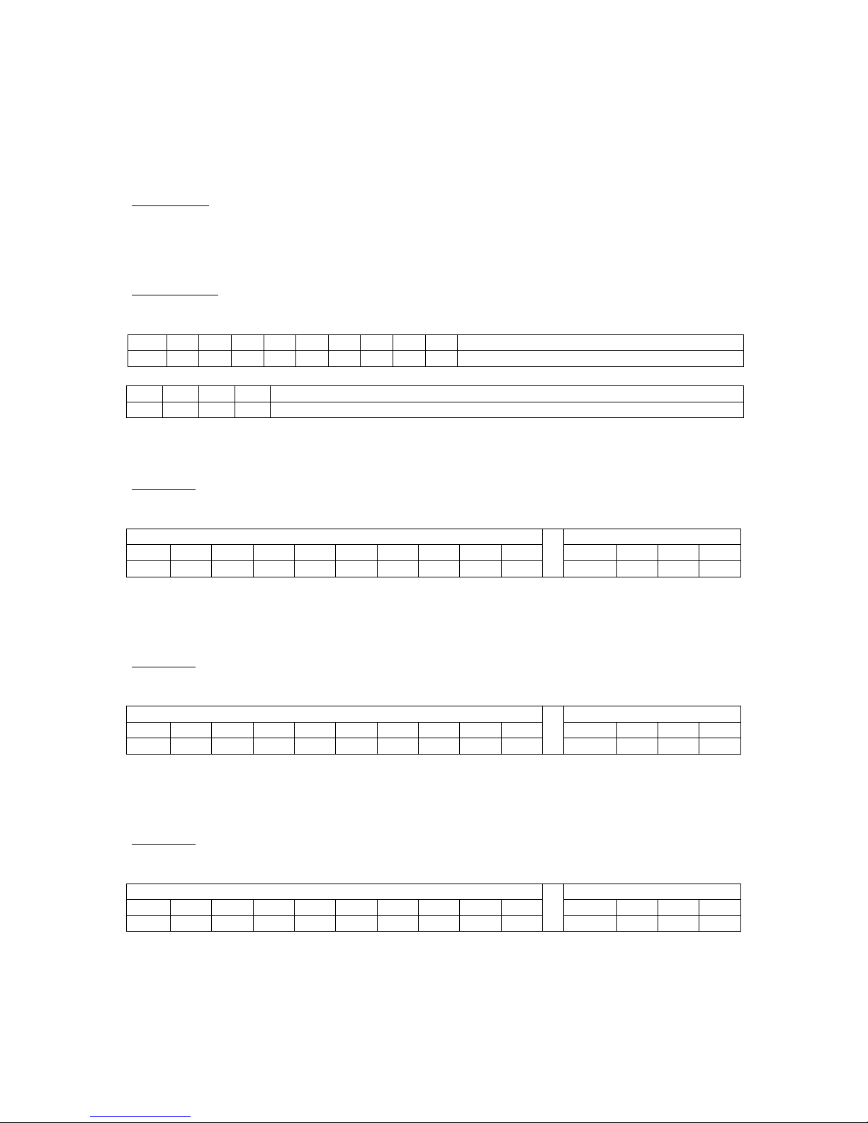
SLAVE1:
SLAVE1, UNIT2, DMX start channel 6:
10 Pin Dipswitch 4 Pin Dipswitch
SW10 SW9 SW8 SW7 SW6 SW5 SW4 SW3 SW2 SW1 SW4 SW3 SW2 SW1
0 0 0 0 0 0 0 1 1 0 0 0 1 1
The item start to receive with the DMX channel 6.
The items consumes ch6, ch7, ch8, ch9, ch 10.
SLAVE2:
SLAVE2, UNIT3, DMX start channel 11:
10 Pin Dipswitch 4 Pin Dipswitch
SW10 SW9 SW8 SW7 SW6 SW5 SW4 SW3 SW2 SW1 SW4 SW3 SW2 SW1
0 0 0 0 0 0 1 0 1 1 0 0 1 1
The item start to receive with the DMX channel 11.
The items consumes ch11, ch12, ch13, ch14, ch15.
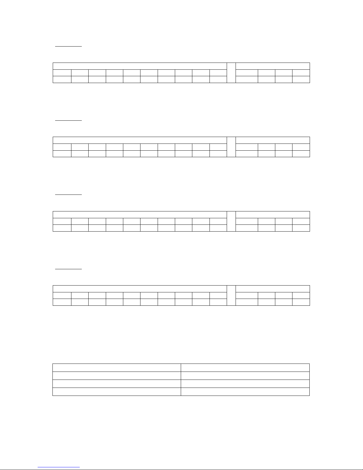
SLAVE3:
SLAVE3, UNIT4, DMX start channel 16:
10 Pin Dipswitch 4 Pin Dipswitch
SW10 SW9 SW8 SW7 SW6 SW5 SW4 SW3 SW2 SW1 SW4 SW3 SW2 SW1
0 0 0 0 0 1 0 0 0 0 0 0 1 1
The item start to receive with the DMX channel 16.
The items consumes ch16, ch17, ch18, ch19, ch20.
Page 28

29
9.5.2 Example B
This example shows how to set up eight LED PARs to be controlled in 5ch DMX master
mode. The patterns are still send out for 4channels.
Connection:
MASTER SLAVE1 SLVAE2 SLAVE3 SLAVE 4 SLAVE 5 SLAVE6 SLAVE8
UNIT1 UNIT2 UNIT3 UNIT4 UNIT5 UNIT6 UNIT7 UNIT8
Master setup:
The master unit, UNIT1, need to be set by this table:
SW10 SW9 SW8 SW7 SW6 SW5 SW4 SW3 SW2 SW1 Colour pattern selection
0 0 0 0 0 1 0 0 1 0 chaser pattern 1, right to left, same colour each step
SW4 SW3 SW2 SW1 Mode
0 1 0 0 DMX master 5ch, speed control by potentiometer
The items consumes ch1, ch2, ch3, ch4, ch5.
SLAVE1:
SLAVE1, UNIT2, DMX start channel 6:
10 Pin Dipswitch 4 Pin Dipswitch
SW10 SW9 SW8 SW7 SW6 SW5 SW4 SW3 SW2 SW1 SW4 SW3 SW2 SW1
0 0 0 0 0 0 0 1 1 0 0 0 1 1
The item start to receive with the DMX channel 6.
The items consumes ch6, ch7, ch8, ch9, ch10.
SLAVE2:
SLAVE2, UNIT3, DMX start channel 11:
10 Pin Dipswitch 4 Pin Dipswitch
SW10 SW9 SW8 SW7 SW6 SW5 SW4 SW3 SW2 SW1 SW4 SW3 SW2 SW1
0 0 0 0 0 0 1 0 1 1 0 0 1 1
The item start to receive with the DMX channel 11.
The items consumes ch11, ch12, ch13, ch14, ch15.
SLAVE3:
SLAVE3, UNIT4, DMX start channel 16:
10 Pin Dipswitch 4 Pin Dipswitch
SW10 SW9 SW8 SW7 SW6 SW5 SW4 SW3 SW2 SW1 SW4 SW3 SW2 SW1
0 0 0 0 0 1 0 0 0 0 0 0 1 1
The item start to receive with the DMX channel 16.
The items consumes ch16, ch17, ch18, ch19, ch20.
Page 29
30
SLAVE4:
SLAVE4, UNIT5, DMX start channel 1:
10 Pin Dipswitch 4 Pin Dipswitch
SW10 SW9 SW8 SW7 SW6 SW5 SW4 SW3 SW2 SW1 SW4 SW3 SW2 SW1
0 0 0 0 0 0 0 0 0 1 0 0 1 1
The item start to receive with the DMX channel 1.
The items consumes ch1, ch2, ch3, ch4, ch5.
SLAVE5:
SLAVE5, UNIT6, DMX start channel 6:
10 Pin Dipswitch 4 Pin Dipswitch
SW10 SW9 SW8 SW7 SW6 SW5 SW4 SW3 SW2 SW1 SW4 SW3 SW2 SW1
0 0 0 0 0 0 0 1 1 0 0 0 1 1
The item start to receive with the DMX channel 6.
The items consumes ch6, ch7, ch8, ch9, ch10.
SLAVE6:
SLAVE6, UNIT7, DMX start channel 11:
10 Pin Dipswitch 4 Pin Dipswitch
SW10 SW9 SW8 SW7 SW6 SW5 SW4 SW3 SW2 SW1 SW4 SW3 SW2 SW1
0 0 0 0 0 0 1 0 1 1 0 0 1 1
The item start to receive with the DMX channel 11.
The items consumes ch11, ch12, ch13, ch14, ch15.
SLAVE7:
SLAVE7, UNIT8, DMX start channel 16:
10 Pin Dipswitch 4 Pin Dipswitch
SW10 SW9 SW8 SW7 SW6 SW5 SW4 SW3 SW2 SW1 SW4 SW3 SW2 SW1
0 0 0 0 0 1 0 0 0 0 0 0 1 1
The item start to receive with the DMX channel 16.
The items consumes ch16, ch17, ch18, ch19, ch20.
Page 30

31
10 DMX slave 3ch
The 3channel slave mode is for use with a standard DMX controller. The LED PAR can be
controller with all 512 channels. Each colour is controlled by one DMX channel. All 512
DMX channels can be used. Dipswitch 1 to 9 sets the first channel to receive.
10.1Mode setting
To enable the DMX slave 3ch mode, set the 4pin dipswitch on the backside of the LED PAR
according to the this table:
SW4 SW3 SW2 SW1 mode
X 1 0 1 DMX slave 3ch
0 = dipswitch is set to off
1 = dipswitch is set to on
X = in this mode there is no speed control by potentiometer or music supported
10.2DMX usage
1. DMX CH = RED
2. DMX CH = GREEN
3. DMX CH = BLUE
Page 31
32
10.3Set up of the first DMX receiving channel
The value of dipswitch 1 to 9 is binary coded. To set a wished DMX receiving channel add
the different values (see example below of the table):
SW10 SW9 SW8 SW7 SW6 SW5 SW4 SW3 SW2 SW1 First DMX receive channel
0 0 0 0 0 0 0 0 0 1 1
0 0 0 0 0 0 0 0 1 0 2
0 0 0 0 0 0 0 1 0 0 4
0 0 0 0 0 0 1 0 0 0 8
0 0 0 0 0 1 0 0 0 0 16
0 0 0 0 1 0 0 0 0 0 32
0 0 0 1 0 0 0 0 0 0 64
0 0 1 0 0 0 0 0 0 0 128
0 1 0 0 0 0 0 0 0 0 256
0 = dipswitch is set to off.
1 = dipswitch is set to on.
Remarks:
In case of all dipswitches 1 to 9 are set to zero, the first DMX receive channel is 1.
I case of only dipswitch 1 is set to on, the first DMX receive channel is 1.
The maximum first receive channel is channel 510.
In case of chosen first receive channel bigger than 510, the maximum receive channel is still
510.
Page 32
33
10.4Examples
10.4.1 Example A, first DMX receive channel is 1
SW10 SW9 SW8 SW7 SW6 SW5 SW4 SW3 SW2 SW1 First DMX receive channel
0 0 0 0 0 0 0 0 0 1 1
The item start to receive with the DMX CH1.
The items consumes CH1, CH2, CH3.
10.4.2 Example B, first DMX receive channel is 22
SW10 SW9 SW8 SW7 SW6 SW5 SW4 SW3 SW2 SW1 First DMX receive channel
0 0 0 0 0 1 0 1 1 0 22
The item start to receive with the DMX CH22.
The items consumes CH22, CH23, CH24.
10.4.3 Example C, first DMX receive channel is 272
SW10 SW9 SW8 SW7 SW6 SW5 SW4 SW3 SW2 SW1 First DMX receive channel
0 1 0 0 0 1 0 0 0 0 272
The item start to receive with the DMX CH272.
The items consumes CH272, CH273, CH274.
10.4.4 Example D, first DMX receive channel is 510
SW10 SW9 SW8 SW7 SW6 SW5 SW4 SW3 SW2 SW1 First DMX receive channel
0 1 1 1 1 1 1 1 1 0 510
The item start to receive with the DMX CH510.
The items consumes CH510, CH511, CH512.
Page 33
34
11 DMX master 3ch
This mode has the same functions as the “DMX master 5ch” mode, chapter 9. The difference
is the using of the DMX channels. In this mode only 3 DMX channels for controlling one unit
are used. In this mode other units than a LED PAR can be connected e.g. a power pack, LED
PARs of different companies which support control of a DMX master.
11.1Mode setting
To enable the DMX master 3ch mode, set the 4pin dipswitch on the backside of the LED PAR
according to the this table:
SW4 SW3 SW2 SW1 mode
X 1 1 0 DMX master 3ch
0 = dipswitch is set to off
1 = dipswitch is set to on
X = see information below/above
11.2Speed setting
SW4 setup the speed source. Choose the speed source according this table
SW4 SW3 SW2 SW1 mode
0 X X X speed control by potentiometer, if selected mode support it
1 X X X speed control by music, if selected mode support it
0 = dipswitch is set to off
1 = dipswitch is set to on
X = see information above
11.3DMX usage for 3ch control
The LED PAR in master mode sent DMX data according to the table below. The connected
slaves need to be set up to a 3 channel salve (see chapter 10).
1. DMX CH = RED
2. DMX CH = GREEN
3. DMX CH = BLUE
4. DMX CH = RED
5. DMX CH = GREEN
6. DMX CH = BLUE
7. DMX CH = RED
8. DMX CH = GREEN
9. DMX CH = BLUE
10. DMX CH = RED
11. DMX CH = GREEN
12. DMX CH = BLUE
Page 34

35
11.4Colour pattern setting
Same settings as in the “DMX master 5ch” mode, chapter 9.4.
Page 35

36
11.5Examples
11.5.1 Example A
This example shows how to set up four LED PARs to be controlled in 3ch DMX master
mode.
Connection:
MASTER SLAVE1 SLVAE2 SLAVE3
UNIT1 UNIT2 UNIT3 UNIT4
Master setup:
The master unit, UNIT1, need to be set by this table:
SW10 SW9 SW8 SW7 SW6 SW5 SW4 SW3 SW2 SW1 Colour pattern selection
0 0 0 0 0 1 0 0 1 0 chaser pattern 1, right to left, same colour each step
SW4 SW3 SW2 SW1 Mode
0 1 1 0 DMX master 3ch
The item show ch1, ch2, ch3.
SLAVE1:
SLAVE1, UNIT2, DMX start channel 4:
10 Pin Dipswitch 4 Pin Dipswitch
SW10 SW9 SW8 SW7 SW6 SW5 SW4 SW3 SW2 SW1 SW4 SW3 SW2 SW1
0 0 0 0 0 0 0 1 0 0 0 1 0 1
The item start to receive with the DMX ch4.
The items consumes ch4, ch5, ch6.
SLAVE2:
SLAVE2, UNIT3, DMX start channel 7:
10 Pin Dipswitch 4 Pin Dipswitch
SW10 SW9 SW8 SW7 SW6 SW5 SW4 SW3 SW2 SW1 SW4 SW3 SW2 SW1
0 0 0 0 0 0 0 1 1 1 0 1 0 1
The item start to receive with the DMX CH7.
The items consumes ch7, ch8, ch9.
SLAVE3:
SLAVE3, UNIT4, DMX start channel 10:
10 Pin Dipswitch 4 Pin Dipswitch
SW10 SW9 SW8 SW7 SW6 SW5 SW4 SW3 SW2 SW1 SW4 SW3 SW2 SW1
0 0 0 0 0 0 1 0 1 0 0 1 0 1
The item start to receive with the DMX CH10.
The items consumes ch10, ch11, ch12.
Page 36
37
11.5.2 Example B
This example shows how to set up eight LED PARs to be controlled in 3ch DMX master
mode. The patterns are still send out for 4channels.
Connection:
MASTER SLAVE1 SLVAE2 SLAVE3 SLAVE 4 SLAVE 5 SLAVE6 SLAVE8
UNIT1 UNIT2 UNIT3 UNIT4 UNIT5 UNIT6 UNIT7 UNIT8
Master setup:
The master unit, UNIT1, the master unit, need to be set by this table:
SW10 SW9 SW8 SW7 SW6 SW5 SW4 SW3 SW2 SW1 Colour pattern selection
0 0 0 0 0 1 0 0 1 0 chaser pattern 1, right to left, same colour each step
SW4 SW3 SW2 SW1 Mode
0 1 1 0 DMX master 3ch
The item show ch1, ch2, ch3.
SLAVE1:
SLAVE1, UNIT2, DMX start channel 4:
10 Pin Dipswitch 4 Pin Dipswitch
SW10 SW9 SW8 SW7 SW6 SW5 SW4 SW3 SW2 SW1 SW4 SW3 SW2 SW1
0 0 0 0 0 0 0 1 0 0 0 1 0 1
The item start to receive with the DMX ch4.
The items consumes ch4, ch5, ch6.
SLAVE2:
SLAVE2, UNIT3, DMX start channel 7:
10 Pin Dipswitch 4 Pin Dipswitch
SW10 SW9 SW8 SW7 SW6 SW5 SW4 SW3 SW2 SW1 SW4 SW3 SW2 SW1
0 0 0 0 0 0 0 1 1 1 0 1 0 1
The item start to receive with the DMX CH7.
The items consumes ch7, ch8, ch9.
SLAVE3:
SLAVE3, UNIT4, DMX start channel 10:
10 Pin Dipswitch 4 Pin Dipswitch
SW10 SW9 SW8 SW7 SW6 SW5 SW4 SW3 SW2 SW1 SW4 SW3 SW2 SW1
0 0 0 0 0 0 1 0 1 0 0 1 0 1
The item start to receive with the DMX ch10.
The items consumes ch10, ch11, ch12.
Page 37
38
SLAVE4:
SLAVE4, UNIT5, DMX start channel 1:
10 Pin Dipswitch 4 Pin Dipswitch
SW10 SW9 SW8 SW7 SW6 SW5 SW4 SW3 SW2 SW1 SW4 SW3 SW2 SW1
0 0 0 0 0 0 0 0 0 1 0 1 0 1
The item start to receive with the DMX ch1.
The items consumes ch1, ch2, ch3.
SLAVE5:
SLAVE5, UNIT6, DMX start channel 4:
10 Pin Dipswitch 4 Pin Dipswitch
SW10 SW9 SW8 SW7 SW6 SW5 SW4 SW3 SW2 SW1 SW4 SW3 SW2 SW1
0 0 0 0 0 0 0 1 0 0 0 1 0 1
The item start to receive with the DMX ch4.
The items consumes ch4, ch5, ch6.
SLAVE6:
SLAVE6, UNIT7, DMX start channel 7:
10 Pin Dipswitch 4 Pin Dipswitch
SW10 SW9 SW8 SW7 SW6 SW5 SW4 SW3 SW2 SW1 SW4 SW3 SW2 SW1
0 0 0 0 0 0 0 1 1 1 0 1 0 1
The item start to receive with the DMX ch7.
The items consumes ch7, ch8, ch9.
SLAVE7:
SLAVE7, UNIT8, DMX start channel 10:
10 Pin Dipswitch 4 Pin Dipswitch
SW10 SW9 SW8 SW7 SW6 SW5 SW4 SW3 SW2 SW1 SW4 SW3 SW2 SW1
0 0 0 0 0 0 1 0 1 0 0 1 0 1
The item start to receive with the DMX ch10.
The items consumes ch10, ch11, ch12.
12 Technical Specifications
36 LEDs, 3W
Number of LEDs 36, 3W
Power supply 230Vac~50HZ
Dimensions PAR 64
Weight 3Kg
 Loading...