

Puls dimension PISA11 Series, PISA11.CLASS2 Datasheet

PISA11.CLASS2
PISA11-Series
PROTECTION MODULE 24V, 4 OUTPUTS
PROTECTION MODULE
One Input and Four Current Controlled Outputs
NEC Class 2 Compliant Outputs
Ensures Sufficient Supply Voltage for Critical Loads
even in the Event of an Fault
Protects Small Cable Sizes against Overload
Hassle-free Turn-on of Loads with Large Input
Capacitors
Wide Temperature Range between -25°C and +70°C
On/Off Function of Outputs
Compact Design, Width only 45mm
Remote Monitoring and Control Functions
3 Year Warranty
1/19
GENERAL DESCRIPTION
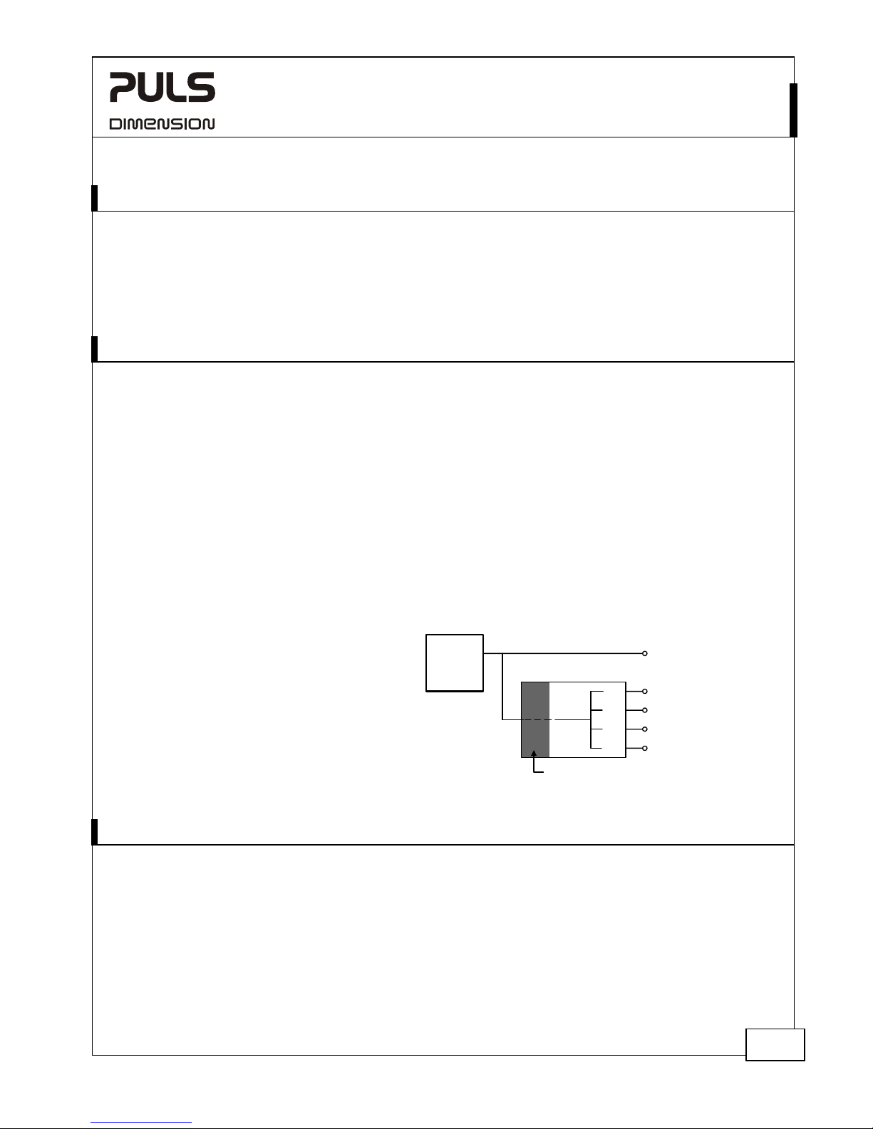
This protection module fulfills two basic functions. First it
distributes the current of a large (non NEC Class 2) power
source to four NEC CLASS 2 output channels and therefore
allows for a simpler wiring method and easier approval
process of the entire machine. The second function is to
permit only so much current on the outputs that the input
voltage of this unit (which corresponds to the output
voltage of the power supply) does not fall below 21V.
This ensures a safe and an uninterrupted supply voltage for
sensitive equipments, such as PLCs, controls or sensors, when
they are
connected
directly to the
same power
supply as the
PISA module.
Less critical
loads that are
not affected to short voltage interruptions or that could
even be the cause of a fault on the 24V power supply are
connected to one of the four NEC CLASS 2 output channels
of the PISA module.
SHORT-FORM DATA
Input voltage DC 24V
Input voltage
range
18 - 30V
Input current typ. 43mA At no load
Number of outputs 4
Output currents 4x 3.7A at 24V
4x 3.2A at 28V
Input voltage
protection levels
typ. 21.4V
Temperature range -25°C to +70°C Operational
-40°C to +85°C Storage
Type of current
limitation
Active current limitation followed
by a shutdown
Dimensions 45x75x91mm *) WxHxD
Non NEC CLASS 2 Load
DC 24V
Power
y
*) Add 13mm in depth for signal connector.
ORDER NUMBERS
Protection PISA11.CLASS2 4x NEC CLASS 2
module outputs
MARKINGS
IND. CONT. E
Q.
UL 508
UL 60950-1
UL 2367
IEC 60950-1
NEC CLASS 2
EMC, LVD
ATEX
II 3G EX nA nC IIC T4
Class I Div 2
Marine
Suppl
NEC CLASS 2 Circuit 2
NEC CLASS 2 Circuit 3
NEC CLASS 2 Circuit 4
NEC CLASS 2 Circuit 1A1
A2
A4
A3
PISA Protection Module
Safeguard
May 2014 / Rev. 1.7 DS-PISA11.CLASS2 - data sheet All parameters are specified at 24Vdc input, 25°C ambient temperature and a 5 minutes run-in time unless otherwise noted.
www.pulspower.com Phone +49 89 9278-0 Germany

PISA11.CLASS2
PISA11-Series
PROTECTION MODULE 24V, 4 OUTPUTS
INDEX
Page Page
1.
Intended Use .......................................................3
2. Product Description.............................................3
3. Installation Requirements...................................3
4. Input ....................................................................5
5. Outputs................................................................5
6. Current Limitation and Shutdown Behavior......6
7. Connecting Capacitive Loads to the Outputs ....8
8. Output-OK Relay Contact ...................................9
9. ON/OFF and Reset Signal Input ..........................9
10. Synchronization of Multiple PISA Modules .......9
11. Functional Diagram...........................................10
12. Back-feeding Loads ...........................................10
13. Power Losses......................................................11
14. Reliability .......................................................... 11
15. Front Side and User Elements .......................... 12
16. Terminals and Wiring....................................... 13
17. EMC ................................................................... 14
18. Environment ..................................................... 15
19. Protection Features .......................................... 16
20. Dielectric Strength............................................ 16
21. Approvals.......................................................... 17
22. Read-out of the Software Revision Level........ 18
23. Physical Dimensions and Weight ..................... 19
24. Accessory........................................................... 19
24.1. ZM3.WALL Wall Mounting Bracket ....... 19
The information presented in this document is believed to be accurate and reliable and may change without notice.
The housing is patent by PULS (US patent No US D442,923S).
No part of this document may be reproduced or utilized in any form without permission in writing from the publisher
(PULS GmbH). This also applies to all kinds of electronic publishing.
TERMINOLOGY AND ABREVIATIONS
DC 24V A figure displayed with the AC or DC before the value represents a nominal voltage with
standard tolerances (usually ±15%) included.
E.g.: DC 12V describes a 12V battery disregarding whether it is full (13.7V) or flat (10V)
24Vdc A figure with the unit (Vdc) at the end is a momentary figure without any additional
tolerances included.
May 2014 / Rev. 1.7 DS-PISA11.CLASS2 - data sheet All parameters are specified at 24Vdc input, 25°C ambient temperature and a 5 minutes run-in time unless otherwise noted.
www.pulspower.com Phone +49 89 9278-0 Germany
2/19
PISA11.CLASS2
PISA11-Series
PROTECTION MODULE 24V, 4 OUTPUTS
1. INTENDED USE
This device is designed for installation in an enclosure and is intended for the general use such as in industrial control,
office, communication, and instrumentation equipment.
Do not use this protection module in equipment, where malfunction may cause severe personal injury or threaten
human life.
This device is designed for use in hazardous, non-hazardous, ordinary or unclassified locations.
2. PRODUCT DESCRIPTION
This protection module fulfills two basic functions. First it distributes the current of a large power source to four NEC
CLASS 2 output channels and therefore allows for a simpler wiring method and easier approval process of the entire machine.
The second function is to permit only so much current on the outputs that the input voltage of this unit (which
corresponds to the output voltage of the power supply) does not fall below 21V. This ensures a reliable supply voltage
for sensitive equipments, such as PLCs, controls or sensors, when they are connected directly to the same power supply
as the PISA protection module.
The protection module has one 24V input and four output channels to which the current is distributed. Each output
channel is equipped with a redundant over-current protection, which avoids that wires will be overloaded. All four
output channels will shutdown simultaneously, if the current of one individual channel or the maximum allowed
current for the protection module is exceeded.
A safeguard circuit in the input stage of the PISA module works like a valve. It permits only so much current that the
input voltage does not drop below 21V. In case the input voltage would fall below this value (e.g. due to overloads,
too small of a power supply or high inrush currents such as from starting a motor), all four output channels will be
actively current limited and will shutdown after a certain period of time.
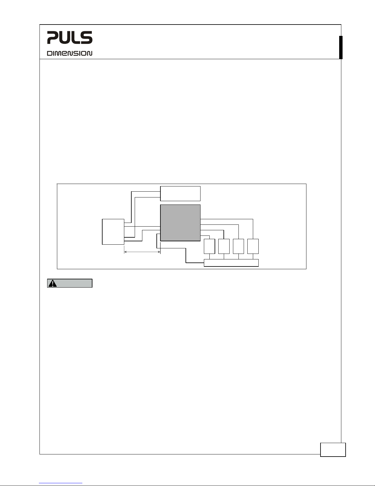
A typical wiring configuration is shown below. All sensitive loads are connected directly to the power supply. If
needed, these load circuits can be protected with standard circuit breakers or fuses. Loads which are less sensitive to
voltage dips or interruptions or which are the source
of the voltage drop themselves are connected to the
output of the PISA protection module.
Non NEC CLASS 2 Load
DC 24V
Power
Supply
NEC CLASS 2 Circuit 2
NEC CLASS 2 Circuit 3
NEC CLASS 2 Circuit 4
NEC CLASS 2 Circuit 1A1
A2
A4
A3
PISA Protection Module
Safeguard
3. INSTALLATION REQUIREMENTS
This protection module is suitable for DIN-rail mounting. Use DIN-Rails according to EN 60715 or EN 50022 with a
height of 7.5 or 15mm.
The protection module can be used with any regulated 24Vdc power supply. If the power source can deliver more than
40A continuous, the PISA module shall be equipped with an external input fuse (e.g. 30/32A). The power capability
and performance of the power supply can limit the output characteristics of the PISA module.
Make sure that the input voltage polarity is correct before applying the input voltage.
Do not connect batteries to the outputs of the PISA11 module.
This device may only be installed and put into operation by qualified personnel.
The unit does not contain serviceable parts.
May 2014 / Rev. 1.7 DS-PISA11.CLASS2 - data sheet All parameters are specified at 24Vdc input, 25°C ambient temperature and a 5 minutes run-in time unless otherwise noted.
www.pulspower.com Phone +49 89 9278-0 Germany
3/19
PISA11.CLASS2
PISA11-Series
PROTECTION MODULE 24V, 4 OUTPUTS
If damage or malfunction should occur during operation, immediately turn power off and send unit to the factory for
inspection.
This device is designed for convection cooling and does not require an external fan. Do not obstruct airflow and do
not cover ventilation grid.
The standard mounting orientation is input terminals on the bottom and output terminals on the top. Do not use the
unit in other mounting orientations.
Keep the following installation clearances:
- Top and bottom: min. 40mm on top, 20mm on the bottom
- Left and right: min. 6.4mm if the ambient temperature is above 60°C.
A high voltage drop between the power supply and the protection module might cause a malfunction. It is not
recommended to use wires longer than 2x2m (for 2.5mm
2
or AWG14 wires) or 2x4m (for 4mm2 or AWG12 wires) to
avoid undesired undervoltage conditions on the input of the protection module.
Use only regulated PULS power supplies to meet the conducted low frequency interference requirements when used in
marine applications according to the GL regulations (section 20 of the GL regulations).
Fig. 3-1 Wiring scheme
24V
Power
Supply
PLC, Controls
(sensitive loads)
-
-
+
+
+
-
PISA
Protection Module
Output 1
+
-
-
Output 2
Output 3
Output 4
Distribution Node
Recommended
Wire:
max. 2x4m, 4mm
2
or 2x2m, 2.5mm
2
Load
4
+
-
Load
3
+
-
Load
2
+
-
Load
1
+
-
WARNING
Risk of electrical shock, fire, personal injury or death.
- Turn power off before working on the device. Protect against inadvertent re-powering.
- Make sure that the wiring is correct by following all local and national codes.
- Do not modify or repair the unit.
- Do not open the unit.
- Use caution to prevent any foreign objects from entering the housing.
- Do not use in wet locations or in areas where moisture or condensation can be expected.
Notes for use in hazardous location areas:
The unit is suitable for use in Class I Division 2 Groups A, B, C, D locations.
The unit is suitable for use in Group II Category 3 (Zone 2) environments and is evaluated according to the EN 60079-
0:2009 and EN 60079-15:2010.
WARNING EXPLOSION HAZARDS!
Substitution of components may impair suitability for this environment. Do not disconnect the unit or operate the
reset button unless power has been switched off or the area is known to be non-hazardous. The signal-connector may
not be used in hazardous location areas unless additional measures are met to avoid an unintended disconnection
(e.g. an additional mechanical fixation). The connection must meet the requirements of the EN 60079-15:2010. A
suitable enclosure must be provided for the end product which has a minimum protection of IP54 and fulfils the
requirements of the EN 60079-15:2010.
May 2014 / Rev. 1.7 DS-PISA11.CLASS2 - data sheet All parameters are specified at 24Vdc input, 25°C ambient temperature and a 5 minutes run-in time unless otherwise noted.
www.pulspower.com Phone +49 89 9278-0 Germany
4/19
PISA11.CLASS2
PISA11-Series
PROTECTION MODULE 24V, 4 OUTPUTS
4. INPUT
Input voltage nom. DC 24V ±25%
Input voltage range - 18Vdc – 30Vdc
max. 30Vdc Absolute maximum continuous input voltage with no
damage to the PISA module
Turn-on voltage typ. 21.4Vdc Required input voltage for turning-on the outputs
Turn-on delay of outputs typ. 270ms Period between applying the input voltage and turning
on the outputs. All outputs will be turned-on at the
same time.
Input voltage protection level *) min.
max.
21.0Vdc
21.8Vdc
Below this voltage level, outputs will shutdown.
Stand-by input current typ. 43mA Stand-by current with no load current on the outputs
*) Voltage dips below this value can occur for maximal 200μs.
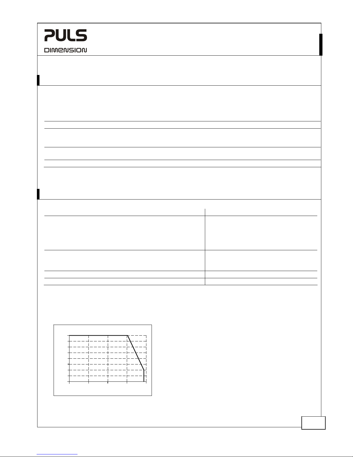
5. OUTPUTS
24V Input 28V Input
Output current output 1 nom. 3.7A 3.2A see Fig. 5-1
output 2 nom. 3.7A 3.2A see Fig. 5-1
output 3 nom. 3.7A 3.2A see Fig. 5-1
output 4 nom. 3.7A 3.2A see Fig. 5-1
All 4 outputs together nom. 14.8A 12.8A
Output current limitation
*)
min. 16.6A 16.6A
typ. 19.9A 19.9A
max. 23.6A 23.6A
Voltage drop
**)
typ. 92mV 81mV
Output leakage current
***)
typ. 0.4mA 0.4mA 0.4mA
*) The current limitation value for the sum of all four output currents. This current can be drawn from each individual output before the
protection module shutdown all four outputs at the same time. Shutdown times can be found in chapter 6.
**) Voltage loss between input and output, when all output channels are loaded with 50% of its nominal current.
***) Output current when outputs have shut down
Fig. 5-1 Output current vs. input voltage
Input
Voltage
22V
01A 3A4A
24V
25V
26V
30V
27V
28V
29V
2A
23V
Output Current, typ
May 2014 / Rev. 1.7 DS-PISA11.CLASS2 - data sheet All parameters are specified at 24Vdc input, 25°C ambient temperature and a 5 minutes run-in time unless otherwise noted.
www.pulspower.com Phone +49 89 9278-0 Germany
5/19
PISA11.CLASS2
PISA11-Series
PROTECTION MODULE 24V, 4 OUTPUTS
6. CURRENT LIMITATION AND SHUTDOWN BEHAVIOR
The PISA11 protection module comprises one common limitation and switching element for all four outputs. In a
protection event, all four outputs limit the current or shutdown at the same time.
The following reasons can cause a limitation of the output currents or a shutdown of the output channels:
1) The output current of one or more output channels was too high.
2) The sum of the output current of all four output channels was exceeded.
3) The outputs needed to be shutdown in order to maintain sufficient input voltage.
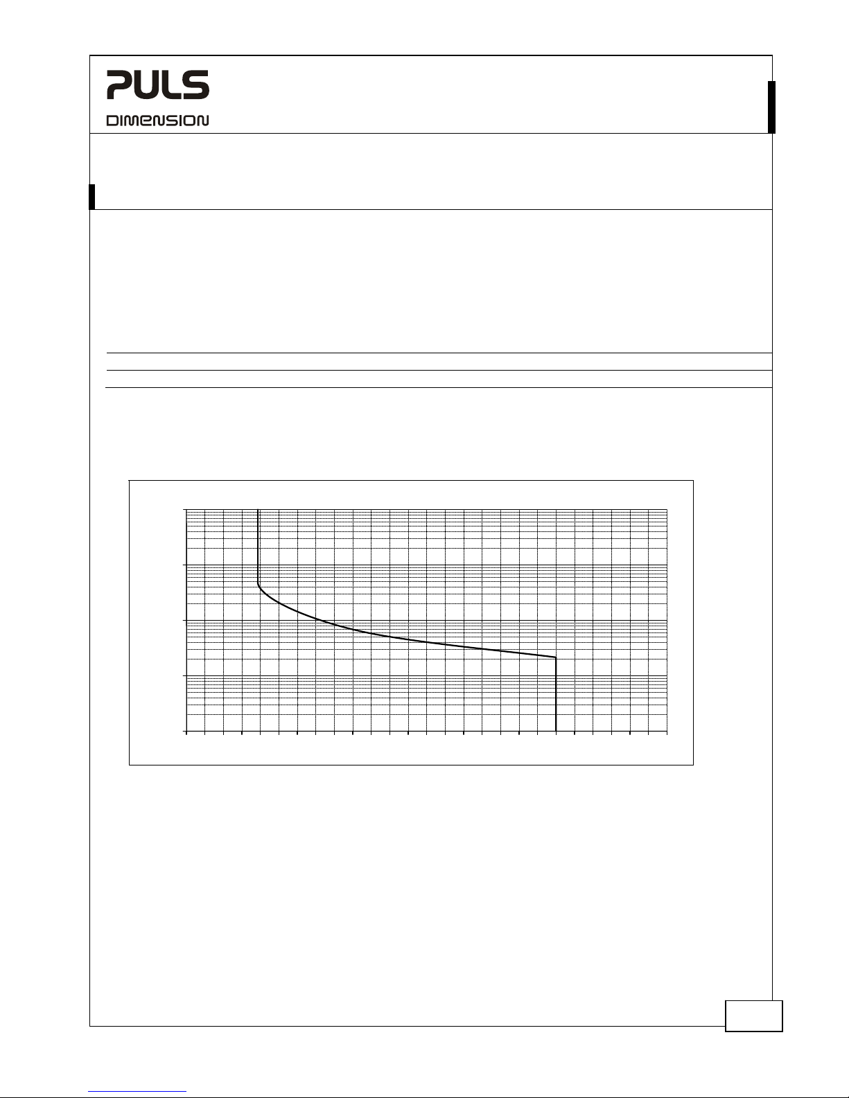
Shutdown times*) when exceeding the rated output current:
At 2-times the rated current
typ. 1s at 7.4A
At short circuit
typ.
10ms
*) The timer for shutdown starts immediately once the rated current levels are exceeded. All output channels will shutdown, if one channel
is overloaded. See Fig. 6-1 for more values.
A shutdown of the outputs can also happen earlier, e.g. when the PISA module has to protect the supply voltage in case the power
supply can not deliver enough current to support all loads without going into overload.
Fig. 6-1 Shutdown characteristic
Shutdown Time, typ.
100ms
Output Current, typ.
0
1s
10s
100s
10ms
2 4 6 8 10 12 14 16 18 20 22 24 26A1 3 5 7 9 11131517192123 25
May 2014 / Rev. 1.7 DS-PISA11.CLASS2 - data sheet All parameters are specified at 24Vdc input, 25°C ambient temperature and a 5 minutes run-in time unless otherwise noted.
www.pulspower.com Phone +49 89 9278-0 Germany
6/19
 Loading...