

Pulsarlube MS60, MS125, MS250 User Manual
Product upgrades may occur without prior notice for quality purposes.
Note: The MS Relay Box was designed for the Pulsarlube MS unit only.
Product warranty will be null &void if any other type of unspecified adapter or converter is used.
The MS functioning process
O
perating Principles
M
ain Unit specification
R
elay Box Specifica
tions
O
perating the Pulsarlube MS
Pulsarlube MS (Machine Synchronized Lubricator)
10 20 30
1) Month setting
2) Working for 10 days
4) Working again for 20 days
5) Finished
Total days
LCD RED LED Signal
lamp blinking
40
250
250
250
250
3) Off for 10 days
Power on
250 250 250
Models Available 60ml, 125ml, 250ml
Operating Pressure 30Kgf/
(425psi)
Operating Temp Range
Multi Point Lubrication Up to 8 points
Power Source DC 4.5V Replaceable Alkaline Battery
Other Functions Same as the Pulsarlube M lubricator
Item Description Image
Voltage Rate Input
Main Unit Side
Input
Output
AC 100~480V, 0.5W
50 ~ 60Hz
Voltage Rate Output Signal (Open collector Type)
Power ON Indicator Red LED
Relay Box Dimensions (mm) 85(D) x 49(W) x 32(H)
1M
4.5M
90mm
Item Description Image
Wire
Length
Power
Supply
Side
Doc No. 1082-000 REV. 140203
The Pulsarlube MS unit turns “On” or “Off” in synchronization with the equipment on which it is installed. It will
dispense the preset amount of grease as long as the machine is operating. If the equipment is not operating,
then the Pulsarlube MS unit goes into “stand-by mode” and does not dispense lubrication until the machine
operates again.
The MS unit is not an externally powered unit. It operates on its own battery.
Battery should be replaced simultaneously with grease pouch. The MS unit will turn ON/OFF
through a Relay Box in accordance with the related equipment power signal.
-15˚C~60˚C (5˚F~140˚F)
Pulsarlube MS (Machine Synchronized Lubricator)
Pulsarlube MS Installation
1. Please install the unit in a convenient location for easy access.
2. Direct or remote mount unit to the bearing/s as you would a Pulsarlube M unit.
3. Connect Male end of Relay Box to the Female end coming from the main body of MS unit.
4. Connect Relay Box wiring to equipments’ power cable
5. It is not necessary to check for wire polarity (+), (-) for the AC power source.
6. Turn POWER button ON and program lubricator by pressing MODE button.
7. Please make sure that red LED blinks once turning power on.
1
2
3
4
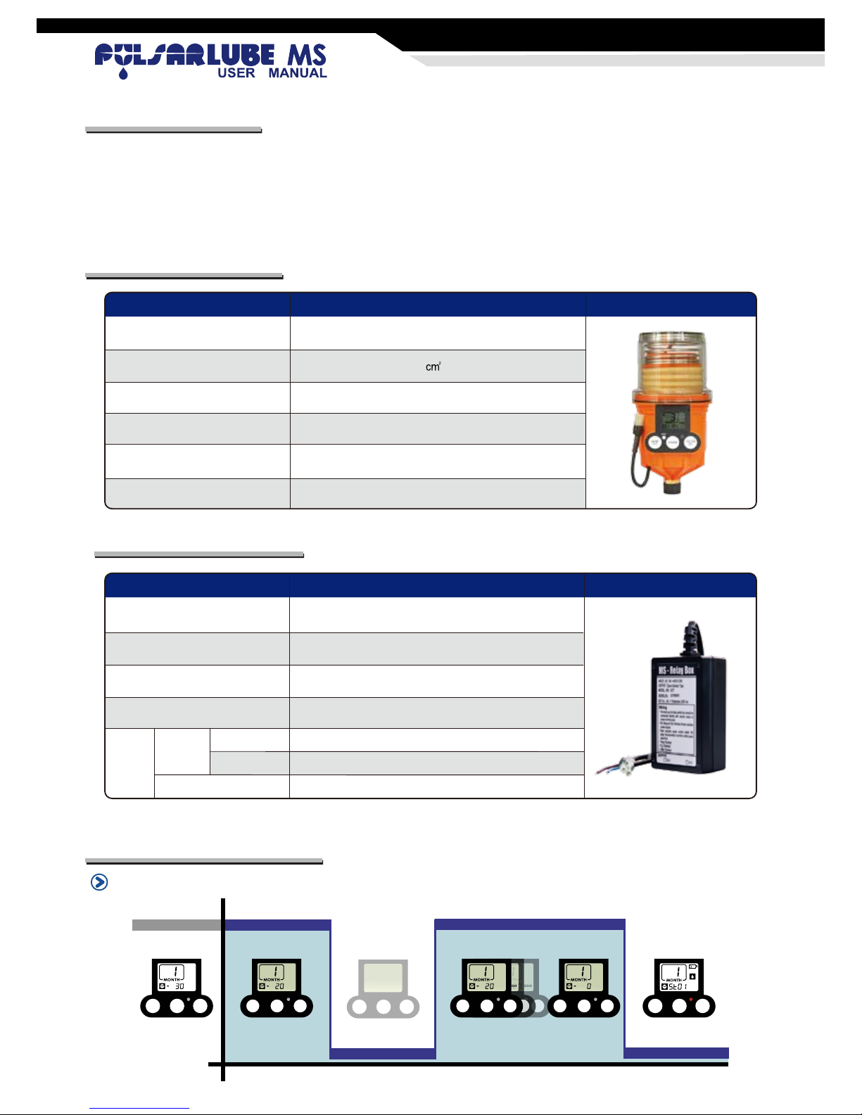
How the MS unit time control programming works (Example: 1 Month Set Mode)
1. If the MS unit is programmed for 1 Month, the # “1” (month) will blink and 30 days will display on the LCD.
2. After 10 days in operation, the “1” will continue to blink and 20 days will display on the LCD. (20 days remaining)
3. MS Unit will go into “stand-by mode” for the amount of time equipment is OFF; in this case = 10days.
LCD will not display during stand-by; however CPU will maintain all data at all times via battery pack back up.
4. If equipment is turned ON i.e. after 10 days, the MS unit will re-activate and dispense for the remaining 20 days.
5. After 40 days (30 days in operation, 10 days in “stand-by mode”); a red LED warning light will be blinking.
6. Please make sure to replace “both” grease pouch and battery pack to avoid lubricator malfunction.
7. After changing service pack, please press “POWER” button and press “MODE” button to program desired setting.
Note !
• The MS unit rate input power is DC 4.5 Voltage.
• The MS unit can be turned off at any time by pressing the “POWER” button for 2 seconds.
• The MS unit will go into stand-by mode 6~7 seconds after equipment has been turned off.
• The equipment that the MS unit is connected to must be ON while programming the lubricator.
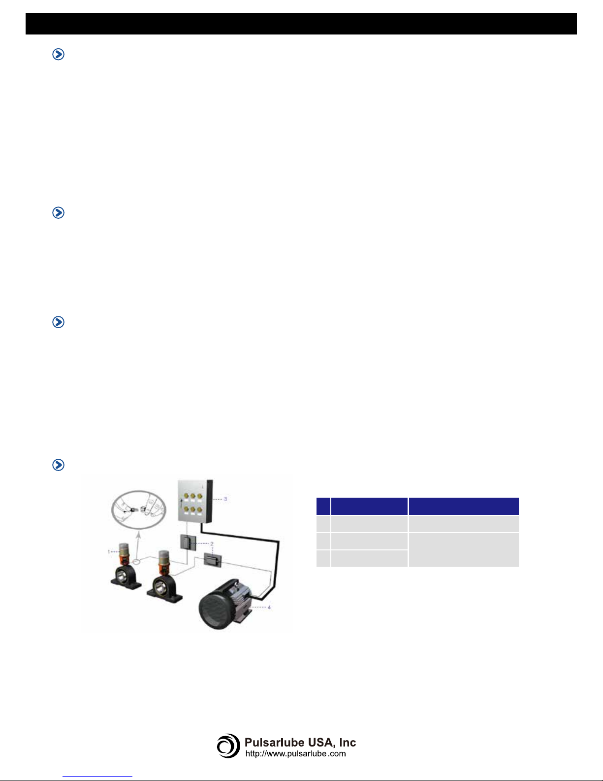
System Connection
Safety Instructions
Please read all safety and operating instructions before using Relay Box. Also, please keep this information for
future references.
• Water and Moisture. The Relay Box should never be used in, or near water or any other chemicals due to
the risk of fatal shock.
• Heat. Never locate the Relay Box near a heat source.
• Dangerous Entry. Care should be taken that no foreign objects or liquids fall or are spilled inside Relay Box.
• Ventilation. Please maintain Relay Box in a well ventilated area to avoid overheating.
• Flammability. Keep Relay Box away from flammable and combustible chemicals.
• Vibration. Keep Relay Box away from high vibration areas.
• Service. The user should not attempt to service the Relay Box beyond what is described in the user manual.
All other servicing should be referred to qualified personnel.
▶ Wiring Options
- Relay Box can be connected directly to the power cable.
- MC (Magnet Coil) Terminal of main machine power source
- Main machine power control switch ON lamp Terminal which is on the control panel case front
- Relay Terminal
- PLC Terminal
- Other Terminal
▶ Equipment
Automatic Lubricator MS series
AC 100 ~ 480 Volt
Connect wire to main machine
power
Relay Box
Control Panel
Electric Motor
 Loading...