

Page 1
Page 2
v.0717
Attention!
Export of models 77337/77338 with a refresh rate of 50 Hz
may have export limitations depending on the laws in your
region.
Attention!
L'exportation des modèles 77337/77338 avec une fréquence
de renouvellement d'images de 50 Hz peut avoir des
restrictions à l'exportation, selon la législation de votre
région.
Achtung!
Export von Modellen 77337/77338 mit 50 Hz
Bildwechselfrequenz kann Exportbeschränkungen je nach
dem Gesetz in Ihrer Region unterliegen.
¡Atención!
La exportación de los modelos 77337/77338 con una
frecuencia de 50 Hz puede tener restricciones de
exportación según la ley en su región.
Attenzione!
L'esportazione dei modelli 77337/77338 con frequenza di 50
Hz può avere limitazioni a seconda delle leggi del tuo paese.
Внимание!
Экспорт моделей 77337/77338 с частотой 50 Гц
может иметь экспортные ограничения в зависимости
от законодательства Вашего региона.
2-15
16-29
30-43
44-57
58-71
72-85
CAMÉRA THERMIQUE QUANTUM
VISOR TÉRMICO QUANTUM
LITE
LITE
LITE
LITE
LITE
LITE
Page 3
3
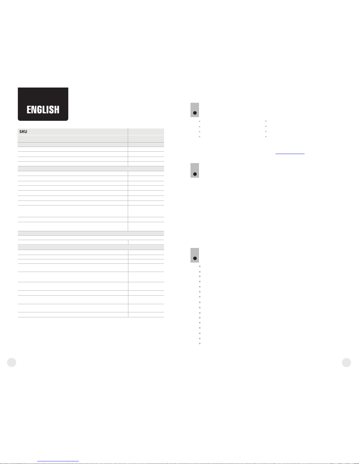
PACKAGE CONTENTS
Thermal Imaging Scope
Carrying case
User manual
Video cable
1
2
Hand strap
Spare battery container
Cleaning cloth
Warranty card
Microbolometer:
Type
Frame rate, Hz
Resolution, pixels
Resolution, pixel
Type
Display:
*
Video output off.
Magnification, x
Digital zoom
Close-up range, m
Exit pupil, mm
Diopter adjustment, D
Operational characteristics:
External power supply
Operating time on battery
pack EPS3 / EPS5), h
Operating time on a battery
set*, h, approx. (t=22 °C)
Degree of protection,
IP code (IEC60529)
Video output
Operating temperature
Dimensions, mm / inch
Weight (without batteries), kg / oz
Field of view, degree / m@100m
- horizontal
- vertical
Power supply
Battery type
Optical characteristics:
Objective lens, mm
Max. observation range of an animal
1.7 m high, m / yard, approx
Relative aperture, D/f'
Pixel size, µm
SPECIFICATIONS:
MODEL Quantum Lite
3
DESCRIPTION
Thermal imaging scopes Quantum based on IR sensor (uncooled
microbolometer) are represented by a number of models featuring
various frame rate, magnification and lens diameter. The scopes are
designed for the use both in the nighttime and in the daylight in
inclement weather conditions (fog, smog, rain) to see through
obstacles hindering detection of targets (branches, tallgrass, thick
bushes etc.). Unlike the image intensifier tube based night vision
devices, thermal imaging scopes Quantum do not require an external
source of light and are not affected by bright light exposure.
Thermal imaging scopes Quantum have a wide range application
including night hunting, observation and terrain orientation, search
and rescue operations.
FEATURES
Detector size 384x288 pixels
Pixel size 17 µm
AMOLED display (640x480 pixels)
Optical magnification 1.8x / 2.5x
Stadiametric rangefinder
Multiple color modes
Digital zoom x2 / x4
Display off function
Three calibration modes – Manual, Automatic, Semi-automatic
Three operating modes - City, Forest, Identification
Defective pixel repair option
Power saving mode
Wide field of view
External power supply
Video output enabling recording
Two ¼” tripod mounts
2
uncooled
IPХ4
IPХ4
384x288
640x480
3
+5/-5
900 / 985
8.4-15 V
5
4÷6 V
9 / 20
12.4 / 21.8
9.3 / 16.3
6.5
384x288
640x480
3
+5/-5
800 / 875
8.4-15 V
5
4÷6 V
9 / 20
PAL/NTSC
16.5 / 29
12.4 / 21.8
6.5
AMOLED
XQ23V XQ30V
77337 77338
18
4xАА 4xАА
23
1.8
2.5
x2 / x4
x2 / x4
1:1.6
1:1.4
17
17
PAL/NTSC
50 50
AMOLED
uncooled
The design and software of this product are subject to change for development purposes.
The latest edition of this user manual is available at www.pulsar-nv.com
Continuous digital zoom, x
1.8-7.2 2.5-10
-25 °С ... +50 °С
200x86x59 /
7.9x3.4x2.3
200x86x59 /
7.9x3.4x2.3
-25 °С ... +50 °С
-13 °F ... 122 °F -13 °F ... 122 °F
0.35 / 12.4
0.35 / 12.4
Page 4

5
4
13
12
16
15
14
COMPONENTS AND CONTROL ELEMENTS
4
5
6
7
8
9
10
11
12
13
14
1
2
3
4
Controller
Button “RF”
Button “MODE”
Button “CAL”
Button “ON”
Eyepiece diopter adjustment ring
Tripod mount ¼”
Weaver rail
Lens focus ring
Wheel for diaphragm opening
Lens diaphragm
Tripod mount ¼”
External power supply jack
Video output
Battery compartment
LED indicator
15
6
2
3
4
5
1
16
1
1
8
7
10
9
Functions of the controls
Controller
Rangefinder
Pass to “Brightness”
mode
Pass to “Contrast” mode
Controls
name
Button
ON
Button
Cal
Button
Mode
Button
RF
Operating mode
Scope is off
Scope is on
Display on
Display off
Scope is on
Scope is on
Brightness
Contrast
1st short press
Turn the scope on
Turn the display off
Subsequent short
press(es)
Display off
Display on
Long press
Turn the
scope off
Rotation
Scope calibration
Calibration is not executed
Zoom
Enter the menu
Rangefinder is on Rangefinder is off
Pass to “Contrast”
mode
Pass to “Brightness”
mode
Color mode
change
Changing
brightness
value
Changing
contrast
value
Changing
distance
value
—
—
—
—
5
MENU AND STATUS BAR ICONS:
M
H
A
Operating mode “Identification”
Manual calibration mode
Semiautomatic calibration mode
Automatic calibration mode
Low battery indicator
Clock setup
2х full magnification
Defective pixel repair option
Operating mode “City”
Operating mode “Forest”
Video output signal selection PAL/NTSC or video output disable
Brightness and contrast setup
Image inversion modes: “White hot”/“Black hot”
Cross for defective pixel repair
Return to default defective pixel pattern
Brightness setting of menu icons
Color modes
Stadiametric rangefinder
Operation on external power supply
2х
—
Page 5

6 7
Turn the lever of the battery compartment (15) 90 degrees in “Open”
position and, pulling by the lug of the cover, remove the battery
container.
Install four AA batteries (or rechargeable batteries) observing polarity
shown on the battery container.
Insert the battery container into the battery compartment and turn the
lever 90 degrees clockwise.
Battery charge level is displayed in the status bar ( ).
In case of complete battery discharge, icon is flashing in the status
bar and in the centre of the display.
INSTALLATION OF BATTERIES
6
Operating mode: City, Forest, Identification.
Calibration mode: Manual, Automatic, Semi-automatic.
Automatic power off. Displayed only when the function is activated.
Image inversion mode. Displayed only when “Black Hot” color mode is
selected.
Zoom. Shows the value of the full optical magnification.
Clock setup. Shows running time in a 12h or 24h format.
Power. Shows current battery status or connection on an external
power supply.
Status bar
The status bar in the lower part of the display shows information as follows:
The functions are shown on the display as follows:
Cal
Mode
Note: to ensure long and reliable operation it is recommended that you
use quality rechargeable batteries with a capacity of at least 2500 mAh.
Please do not use batteries of different types or batteries with various
charge levels.
EXTERNAL POWER SUPPLY
7
The scope can be powered with an external DC power supply (2.1mm
pin) with stabilised voltage ranging from 8.4V to 15V or a 12V vehicle
socket.
х2.5
External power supply (AC/DC) is to be connected to “Power” (13) jack
located on the bottom side of the device.
Please note that the central pin of the power supply that you connect to
the “power” jack of the riflescope, must have marking “+”. The power
supply may have marking - +
The power supply may have marking .
Connection of an external power supply (icon on the status bar)
automatically cuts off power supply from batteries.
External power supply DOES NOT charge the batteries in the
sight!
Attention! We suggest that you use battery packs EPS3I or EPS5
ensuring from 9 to 20 hours of continuous operation.
OPERATION
8
WARNING! Do not point the objective lens of the unit at intensive
sources of light such units emitting laser radiation or the sun. This
may disable unit’s electronic components. The warranty does not
cover damage caused by improper operation.
Switching on and calibration
Press “ON” (6) to switch on the unit. Green LED indicator (16) will
light up. In case of low battery the LED will turn red and battery icon
will start flashing.
Do the calibration of image. Calibration levels background
temperature of the microbolometer and eliminates image flaws.
There are three calibration modes: manual (M), semiautomatic (H)
and automatic (А).
Manual calibration mode
The lens cap should be closed (a diaphragm (11) inside the
objective lens plays the role of the cap). Rotate the wheel (10)
clockwise to open the diaphragm, counterclockwise to close it).
Turn on the unit, press and hold the controller (1) for two seconds to
enter the menu.
Rotate the controller to select option Cal. Press the controller.
Rotate the controller to select mode М. Press the controller to
confirm. To exit the menu, press and hold the controller for two
seconds or wait 10 seconds for automatic exit.
Press the CAL (4) button to calibrate. The image will freeze for 1-2
seconds. Then open the lens cap. Calibration is completed.
In case you see image flaws (such as frozen image, vertical stripes
etc.) re-calibrate the unit.
Semiautomatic calibration mode
Turn on the unit, open the lens cap.
Press and hold the controller (1) for two seconds to enter the menu.
Rotate the controller to select option Cal. Press the controller.
Rotate the controller to select mode H. Press the controller to
confirm.
Press the CAL (4) button to calibrate. The image will freeze for 1-2
seconds.
Calibration is completed.
Page 6

9
8
Automatic calibration mode
With the automatic calibration mode the thermal imager calibrates by
itself according to the software algorythm. The detector (microbolometer)
is closed with the shutter automatically. User assisted calibration with the
CAL (4) button is allowed in this mode.
Turn on the unit, open the lens cap.
Press and hold the controller (1) for two seconds to enter the menu.
Rotate the controller to select option Cal. Press the controller.
Rotate the controller to select mode A. Press the controller to confirm.
At the moment of the automatic calibration the image will freeze for
1-2 seconds.
Calibration is completed.
Note. Automatic calibration may take place more often within several
minutes after the unit is turned on.
Focusing and image adjustment
Open the lens cap.
Adjust sharp image of the display icons by turning the eyepiece diopter
adjustment ring (6).
To adjust display brightness, rotate the controller (1). Respective
brightness level (from 0 to 20) appears next to brightness icon
in the upper right portion of the display.
To adjust display contrast, press briefly the controller (1) (contrast icon
appears ) and rotate it. Respective contrast level (from 0 to 20)
appears next to contrast icon in the upper right portion of the display.
Point the unit at a warm object located at a certain distance, 100
meters, for example.
Achieve a sharp image by turning the lens focus ring (9).
After this adjustment no further dioptre adjustment should be required,
regardless of distance or other factors. Adjust image quality only with
the lens focus ring.
Stadiametric rangefinder
Thermal imagers are equipped with a stadiametric rangefinder which
allows the user to estimate approximate distance to an object with known
size.
Press the “RF” (2) button to activate the rangefinder.
You will see on the display: cursor, measurement distance value and
icons of reference objects for measurement.
There are three pre-set reference objects:
Hare – height 0.3 m
Wild hog – height 0.7 m
Deer – height 1.7 m
85m
200m
487m
Locate the lower fixed cursor under the observed object
and, while rotating the controller (1), move the upper
horizontal cursor relative to the lower fixed cursor until the
observed object fully fits between the two cursors. The
distance to the observed object is automatically
recalculated as you move the upper line.
If the measurement does not take place within 10 seconds, the
rangefinder turns off automatically.
Before being shown on the display, a measured distance value is
rounded up to 5 m for larger values, rounded down to 1m for smaller
values.
To deactivate the rangefinder. Press the “RF” button.
MENU
9
The menu includes options as follows:
Color modes
Selection of operating mode
Selection of calibration mode
Video output setup
Clock setup
Defective pixel repair
Brightness setting of menu icons
Selection of units of measurement
M/Y
M/Y
TAB M1 FUNCTIONS:
Color modes
This menu option allows the user to switch from the standard mode
(“White Hot”) to one of the multiple color modes:
“Black Hot”
“Red Hot”
“Red Monochrome”
“Rainbow”
“Ultramarine”
“Violet”
“Sepia”
Press and hold down the controller (1) for two seconds to enter the
menu.
Rotate the controller to select menu option . Press the controller.
Rotate the controller to select one of the color modes, press the
controller to confirm.
Page 7

10
11
After exiting the menu, the color mode selected by user becomes a default
mode and it is saved upon turning the unit off. When pressing the “MODE”
(3) button for two seconds, color mode will switch to standard mode
“White Hot”.
Selection of operating mode
There are three automatic operating modes:
“City” (enhanced contrast), “Forest” (low contrast) and “Identification”
(improved detail rendering).
Each mode includes optimal combination of parameters (brightness,
contrast, gain etc.) to deliver best possible image in specific viewing
conditions.
Press and hold the controller (1) for two seconds to enter the menu.
Rotate the controller to select Mode option. Press the controller.
Rotate the controller to select icon
(mode “City”) or
(mode “Forest”) or
(mode “Identification”).
Press the controller to confirm.
Icon of the selected mode is shown in the status bar in the lower portion
of the display.
Selection of calibration mode
Please read detailed description in the section “Switching on and
calibration” in section 8 “Operation”.
Clock Setup
Press and hold the controller (1) for two seconds to enter the menu.
Rotate the controller to select icon . Press the controller.
Move the cursor by rotating the controller to select time format “24” or
“AM/PM”.
Press the controller to proceed to hour setup. Set the hour by rotating
the controller.
Press the controller to proceed to minute setup. Set the minute by
rotating the controller.
To save set values and to exit main menu, press and hold the controller
for two second.
Defective pixel repair
When operating a thermal imager, defective (dead) pixels (bright or
dark dots with constant brightness) may appear on the detector, which
are visible on the image. Thermal imagers Quantum allow the user to
repair defective pixels on the detector using a software-based method.
Press and hold the controller (1) for two seconds to enter the menu.
Rotate the controller to select icon and press the controller.
Select icon in the pop-up submenu and press the controller.
A red cross appears in the centre of display, coordinates (X;Y)
of the cross relative to the centre of display appear in the place
of pop-up icons, icons disappear.
Rotate the controller to align the cross with a defective pixel
(defective pixel should go out).
Switch direction of the cross from horizontal to vertical by a short
press of the controller.
After the centre of the cross is aligned with a defective pixel, press
the “Mode” (3) button to repair a pixel.
In case of success a short “OK” message appears in place of the
coordinates.
Further on, move the cross to repair another defective pixel. When
moving the cross to the coordinates area, the latter goes to the lower
right portion of the display.
X=50
Y=50
Selection/disable of video output signal
Press and hold the controller (1) for two seconds to enter the menu.
Rotate the controller to select icon . Press the controller.
Rotate the controller to select video output signal – PAL or NTSC
(video output is off by default).
To disable the video output, select “OFF”. Disabled video output
reduces power consumption of the thermal imager.
To exit the main menu, keep the controller pressed for two seconds or
wait 10 seconds to exit automatically.
Return to default defective pixel pattern.
If you wish to return to the default defective pixel pattern
(i.e. restore all defective pixels previously repaired), select icon in the
pop-up submenu and press the controller.
Options “Yes” and “No” appear on the right of the icon.
Rotate the controller to select “Yes” and press the controller.
If you choose not to return to default pixel pattern, select “No” and press
the controller.
To exit the submenu, keep the controller pressed for two seconds or wait
10 seconds.
Attention! One or two pixels in the form of bright white or colour (blue,
red) 1-2 pixels dots are allowed on the display of thermal imager. These
pixels cannot be repaired and are not a defect.
Brightness setting of menu icons
Press and hold the controller (1) for two seconds to enter the menu.
Rotate the controller to select icon . Press the controller.
Rotate the controller to select brightness level of icons from 1 to 10.
To exit the main menu, keep the controller pressed for two seconds or
wait 10 seconds to exit automatically.
Selection of units of measurement
Press and hold the controller (1) for two seconds to enter the menu.
Rotate the controller to select icon . Press the controller.
Rotate the controller to select “M” – metres or “Y” – yards.
M/Y
M/Y
Page 8

12
13
Press briefly the controller to confirm your choice.
Unit of measurement icon is shown together with measured readings.
To exit the submenu, keep the controller pressed for two seconds or
wait 10 seconds to exit automatically.
Digital zoom
To activate digital zoom, press briefly button “Mode” (3).
Digital zoom change is shown as a pop-up symbol and takes place
repeatedly, when the final value is reached, the first value is shown
(see table below).
Set value of the full optical magnification is shown in the status bar.
The unit does not save the magnification value. Upon turning the unit
on, full optical magnification will correspond to the value of optical
magnification with x1 ratio.
Magnification ratio
Model Optical magnification x1 x2 x4
Full optical magnification
1.6х
3.1x
XQ23V
XQ30V
1.8х 3.6x 7.2x
2.5x 5.0x 10.0x
Monoculars are equipped with a video output to connect external
recording devices and to transmit video signal to monitors, TV sets etc.
VIDEO OUTPUT
10
To record video you can use video recorders such as Yukon MPR
(#27041).
Make sure that the unit is turned off.
Use the included video cable to connect a peripheral device to the
“Video out” jack (14). Turn on the unit.
Select a suitable video output standard - PAL or NTSC (refer to the
respective menu option). A peripheral device will show the image seen
through the scope.
ACCESSORIES
11
Using the Weaver mounting rail (8), you can attach various accessories
to the Quantum scopes, such as Battery Pack EPS3I (SKU#79113).
The ¼” tripod mounts from both sides of the scope are designed to
have the scope installed on a tripod or have a hand strap (included)
attached.
Using the DNV Pulsar Battery Double Pack (#79176) you can
significantly extend the self-contained operating time of your
monocular.
CARE AND MAINTENANCE
12
The thermal imaging scopes have IPX4 degree of protection
(splashproof) but they are not intended for submersion into water.
Attempts to disassemble or repair the scope will void the
warranty!
Clean the scope's optical surfaces only if necessary, and use
caution. First, remove (by blowing with a blower brush or canned air)
any dust or sand particles. Then proceed to clean by using
camera/lens cleaning equipment approved for use with multicoated
lenses. Do not pour the solution directly onto the lens!
TROUBLESHOOTING
13
Listed below are some potential problems that may occur when using
the scope. Carry out the recommended checks and troubleshooting
steps in the order listed. Please note that the table does not list all of
the possible problems. If the problem experienced with the scope is
not listed, or if the suggested action meant to correct it does not
resolve the problem, please contact the manufacturer.
The scope can be used in operating temperatures ranging from
-25 °C to +50 °C. However, if it has been brought indoors from cold
temperatures, do not turn it on for at least 2-3 hours. This will prevent
external optical surfaces from fogging.
Always store the unit in its carrying case in a dry, well-ventilated
space.
Remove the batteries if the scope is not going to be used for an
extended period (longer than one month).
Batteries shall not be exposed to excessive heat such as sunshine,
fire or the like.
Page 9

14
15
PROBLEM
POSSIBLE CAUSE CORRECTIVE ACTION
The unit will
not turn on.
The image is blurry, with
vertical stripes and uneven
background.
The image is too dark.
Batteries have been
wrongly installed.
Oxidized contact points in
the battery compartment
due to “leaky” batteries or
contact points becoming
exposed to a chemically
reactive solution.
One or several batteries
are fully exhausted or
defective.
Calibration is to be done.
Brightness or contrast level
is too low.
Reinstall the batteries
observing polarity.
Clean the battery
compartment, focusing on
the contacts.
Install fresh batteries.
Do the calibration
according to section 8
“OPERATION”.
Adjust brightness/contrast
by rotating the controller.
The unit does not operate
on external power supply.
Charge the power supply
(if required).
Poor image quality /
Detection range decreases.
Problems described may arise in inclement weather
conditions (snow, rain, fog etc.).
Make sure your power
supply provides output
voltage.
Click on the link to read frequently questions on thermal vision
http://www.pulsar-nv.com/support/faq/
No image when recording
video signal from the
thermal imager using an
external video recorder.
Video output of the thermal
imager is disabled.
No connection.
Activate the video output
(s ee poi nt “S ele ctio n/
Disable of video output
signal”, chapter MENU).
Make sure the video cable is
securely connected.
When using the scope at
negative temperatures
image quality is worse than
at positive temperatures.
Due to various thermal conductivity, objects (surrounding
environment, background) under observation get warm faster
at positive temperatures, which allows higher temperature
contrast and, thus, quality of the image produced by a thermal
imager, will be better.
At low operating temperatures objects under observation
(background) normally cool down to roughly equal
temperatures which leads to lower temperature contrast, and
to image quality (precision) degradation. This is normal for
thermal imaging devices.
 Loading...