

Pulsar ULTRA TWIN Instruction Manual
ULTRA TWIN (UL)
INSTRUCTION MANUAL


ULTRA TWIN (UL) (FIRST EDITION REV 1)
June 2011
Part Number M-192-6-001-1U
COPYRIGHT
© Pulsar Process Measurement Limited, 2005 -11. All rights reserved. No part of this publication may be
reproduced, transmitted, transcribed, stored in a retrieval system, or translated into any language in any
form without the written permission of Pulsar Process Measurement Limited.
WARRANTY AND LIABILITY
Pulsar Process Measurement Limited guarantee for a period of 2 years from the date of delivery that it
will either exchange or repair any part of this product returned to Pulsar Process Measurement Limited if
it is found to be defective in material or workmanship, subject to the defect not being due to unfair wear
and tear, misuse, modification or alteration, accident, misapplication or negligence.
DISCLAIMER
Pulsar Process Measurement Limited gives nor implies any process guarantee for this product, and shall
have no liability in respect of any loss, injury or damage whatsoever arising out of the application or use
of any product or circuit described herein.
Every effort has been made to ensure accuracy of this documentation, but Pulsar Process Measurement
Limited cannot be held liable for any errors.
Pulsar Process Measurement Limited operates a policy of constant development and improvement and
reserves the right to amend technical details as necessary.
TECHNICAL ENQUIRIES
Please contact Pulsar Process Measurement Limited for technical support.
COMMENTS AND SUGGESTIONS
If you have any comments or suggestions about this product, then please contact:
Pulsar Process Measurement Limited
Pulsar Process Measurement Inc.
Cardinal Building
Enigma Business Centre
Sandy’s Road
Malvern
Worcestershire
WR14 1JJ
United Kingdom
PO Box 5177
Niceville
FL 32578 - 5177
USA
Tel: + 44 (0) 1684 891371
Fax: + 44 (0) 1684 575985
Tel: + 1 850 279 4882
Fax: + 1 850 279 4886
Web Site: http://www.pulsar-pm.com
e-mail: info@pulsar-pm.com (general
information)
e-mail: support@ pulsar-pm.com (product
support)
Web Site: http://www.pulsar-pm.com
e-mail: info.usa@pulsar-pm.com (general
information)
e-mail: support.usa@ pulsar-pm.com (product
support)


Contents
Chapter 1 Start Here… ......................................................................................................................................... 1
About this Manual ........................................................................................................................................... 1
About the Ultra Twin ...................................................................................................................................... 2
Functional Description .................................................................................................................................... 2
Product Specification....................................................................................................................................... 4
EC Declaration of Conformity ........................................................................................................................ 6
Wall Mount .............................................................................................................................................. 6
Fascia Mount ........................................................................................................................................... 7
Chapter 2 Installation............................................................................................................................................ 9
Power Supply Requirements ........................................................................................................................... 9
Safety Symbols ................................................................................................................................................ 9
Location ......................................................................................................................................................... 10
Dimensions .................................................................................................................................................... 11
Wall mount ............................................................................................................................................ 11
Fascia Mount ......................................................................................................................................... 14
Terminal Connection Details ........................................................................................................................ 15
Wall Mount ............................................................................................................................................ 15
Fascia Mount ......................................................................................................................................... 16
Fuse Location ................................................................................................................................................ 22
Wall mount ............................................................................................................................................ 22
Fascia mount .......................................................................................................................................... 22
Preparation for Operation .............................................................................................................................. 23
Maintenance ................................................................................................................................................... 24
Chapter 3 How To Use Your Ultra Twin ......................................................................................................... 25
Operating the Controls .................................................................................................................................. 25
Display ................................................................................................................................................... 25
Run Mode .............................................................................................................................................. 27
Program Mode ....................................................................................................................................... 27
How to Access Program Mode ..................................................................................................................... 28
Test Mode ...................................................................................................................................................... 33
Using the RS232 Serial Interface .................................................................................................................. 34
Parameter Defaults ........................................................................................................................................ 36
Factory Defaults ..................................................................................................................................... 36
Chapter 4 Quick Set-up Guide ............................................................................................................................. 37
Level or Volume ............................................................................................................................................ 38
Example 1 Level Monitoring with Alarms .......................................................................................... 44
Example 2 Level Monitoring and Control (up or down) ..................................................................... 46
Example 3 Volume Application ........................................................................................................... 48
Example 4 : Differential Control........................................................................................................... 50
Pump .............................................................................................................................................................. 54
Example 1 Sump Control (pump down) ............................................................................................. 59
Example 2 Reservoir Control (pump up) ............................................................................................. 61
Flow ............................................................................................................................................................... 63
Exponential Devices ...................................................................................................................................... 70
Point of Measurement ........................................................................................................................... 71
Calculations ............................................................................................................................................ 73
Example 1 ‘V’ Notch Weir ................................................................................................................. 74
BS3680 Flumes ............................................................................................................................................. 76
Point of Measurement ........................................................................................................................... 76
Calculations ............................................................................................................................................ 77

Example 2 BS3680 U-Throated Flume ............................................................................................... 79
BS3680 Thin Plate Weirs .............................................................................................................................. 81
Point of Measurement ........................................................................................................................... 81
Calculations ............................................................................................................................................ 81
Example 3 BS3680 Rectangular Weir ................................................................................................. 83
BS3680 Rectangular Broad Crested Weir .................................................................................................... 85
Point of Measurement ........................................................................................................................... 85
Calculations ............................................................................................................................................ 85
Special Devices .............................................................................................................................................. 86
Point of Measurement ........................................................................................................................... 86
Calculations ............................................................................................................................................ 87
Universal Calculations .................................................................................................................................. 88
Point of Measurement ........................................................................................................................... 88
Calculations ............................................................................................................................................ 88
Chapter 5 Parameter Guide .............................................................................................................................. 89
Menu System Diagrams ................................................................................................................................ 89
Top Level Menu .................................................................................................................................... 89
Application Menu .................................................................................................................................. 90
Relays Menu .......................................................................................................................................... 91
Pump “Advanced” ................................................................................................................................. 92
Digital Inputs.......................................................................................................................................... 93
Data Logs ............................................................................................................................................... 94
Volume Menu ........................................................................................................................................ 95
OCM Menu ............................................................................................................................................ 96
Display ................................................................................................................................................... 97
mA Output 1 Menu ............................................................................................................................... 98
mA Output 2 Menu ............................................................................................................................... 98
Compensation ........................................................................................................................................ 99
Stability Menu........................................................................................................................................ 99
Echo Processing Menu ........................................................................................................................ 100
System Menu ....................................................................................................................................... 101
Device Comm Menu ........................................................................................................................... 102
Test Menu ............................................................................................................................................ 103
Parameter Listing ......................................................................................................................................... 104
Application Parameters ............................................................................................................................... 104
System Units ........................................................................................................................................ 104
Operation .............................................................................................................................................. 104
Dimensions .......................................................................................................................................... 106
Relay Parameters ......................................................................................................................................... 108
Alarms .................................................................................................................................................. 109
Pumps ................................................................................................................................................... 117
Control.................................................................................................................................................. 121
Miscellaneous ...................................................................................................................................... 126
Common Parameters ........................................................................................................................... 128
Pump “Advanced” Parameters ................................................................................................................... 129
Pump Run On ...................................................................................................................................... 129
Starting ................................................................................................................................................. 129
Stopping ............................................................................................................................................... 130
Pump Exercising .................................................................................................................................. 130
Wall Cling ............................................................................................................................................ 131
Digital Inputs ............................................................................................................................................... 132
About Digital Inputs ............................................................................................................................ 132
Digital Input Parameters .............................................................................................................................. 138
Common Par. ....................................................................................................................................... 138
Digital Inputs........................................................................................................................................ 140
Data Log Parameters ................................................................................................................................... 143

Totaliser Audits .................................................................................................................................... 143
Temperature ......................................................................................................................................... 143
Pump Logs ........................................................................................................................................... 144
Volume......................................................................................................................................................... 145
Conversion ........................................................................................................................................... 146
Breakpoints .......................................................................................................................................... 150
Tables ................................................................................................................................................... 151
OCM Parameters ......................................................................................................................................... 152
PMD Setup........................................................................................................................................... 152
Dimensions .......................................................................................................................................... 155
Calculations .......................................................................................................................................... 158
Breakpoints .......................................................................................................................................... 159
Tables ................................................................................................................................................... 159
Average Flow ...................................................................................................................................... 160
Display Parameters ...................................................................................................................................... 160
Options ................................................................................................................................................. 160
Failsafe ................................................................................................................................................. 162
Auxiliary .............................................................................................................................................. 163
Totaliser ................................................................................................................................................ 165
Bargraph ............................................................................................................................................... 167
mA Output 1 Parameters ............................................................................................................................. 168
Range ................................................................................................................................................... 168
Operaton ............................................................................................................................................... 169
Setpoint ................................................................................................................................................ 170
Limits ................................................................................................................................................... 170
Trim ...................................................................................................................................................... 171
Failsafe ................................................................................................................................................. 171
Allocation ............................................................................................................................................. 172
mA Output 2 Parameters ............................................................................................................................. 173
Range ................................................................................................................................................... 173
Operation .............................................................................................................................................. 174
Setpoint ................................................................................................................................................ 175
Limits ................................................................................................................................................... 175
Trim ...................................................................................................................................................... 176
Failsafe ................................................................................................................................................. 176
Allocation ............................................................................................................................................. 177
Compensation Parameters ........................................................................................................................... 178
Offset .................................................................................................................................................... 178
Temperature ......................................................................................................................................... 178
Velocity ................................................................................................................................................ 179
Stability Parameters ..................................................................................................................................... 180
Damping............................................................................................................................................... 180
Indicator ............................................................................................................................................... 180
Rate....................................................................................................................................................... 180
Filters .................................................................................................................................................... 181
Echo Processing Parameters ....................................................................................................................... 182
Transducer 1 Status ............................................................................................................................. 182
Transducer 2 Status ............................................................................................................................. 183
System Parameters ...................................................................................................................................... 184
Passcode ............................................................................................................................................... 184
Backup ................................................................................................................................................. 184
System Information ............................................................................................................................. 185
Date & Time ........................................................................................................................................ 186
LED Colour ......................................................................................................................................... 186
Watchdog ............................................................................................................................................. 187
Daylight Saving Time ......................................................................................................................... 188
Device Comm. ............................................................................................................................................. 191

RS232 Set Up ...................................................................................................................................... 191
RS 485 Set Up (Optional) ................................................................................................................... 191
Remote Alarm...................................................................................................................................... 192
Test Parameters ............................................................................................................................................ 193
Simulation ............................................................................................................................................ 193
Test Setup ............................................................................................................................................. 194
Hardware .............................................................................................................................................. 195
Chapter 6 Troubleshooting .............................................................................................................................. 197
Parameter Record .............................................................................................................................................. 199

Page 1
Chapter 1 Start Here…
Congratulations on your purchase of a Pulsar Ultra Twin. This quality
system has been developed over many years and represents the latest in high
technology ultrasonic level measurement and control.
It has been designed to give you years of trouble free performance, and a
few minutes spent reading this operating manual will ensure that your
installation is as simple as possible.
About this Manual
It is important that this manual is referred to for correct installation and
operation.
There are various parts of the manual that offer additional help or
information as shown.
Tips
TIP
At various parts of this
manual you will find tips to
help you.
Additional Information
Additional Information
At various parts of the manual, you will find
sections like this that explain specific things in
more detail.
References
See Also
References to other parts of the manual
Page 2
About the
Ultra Twin
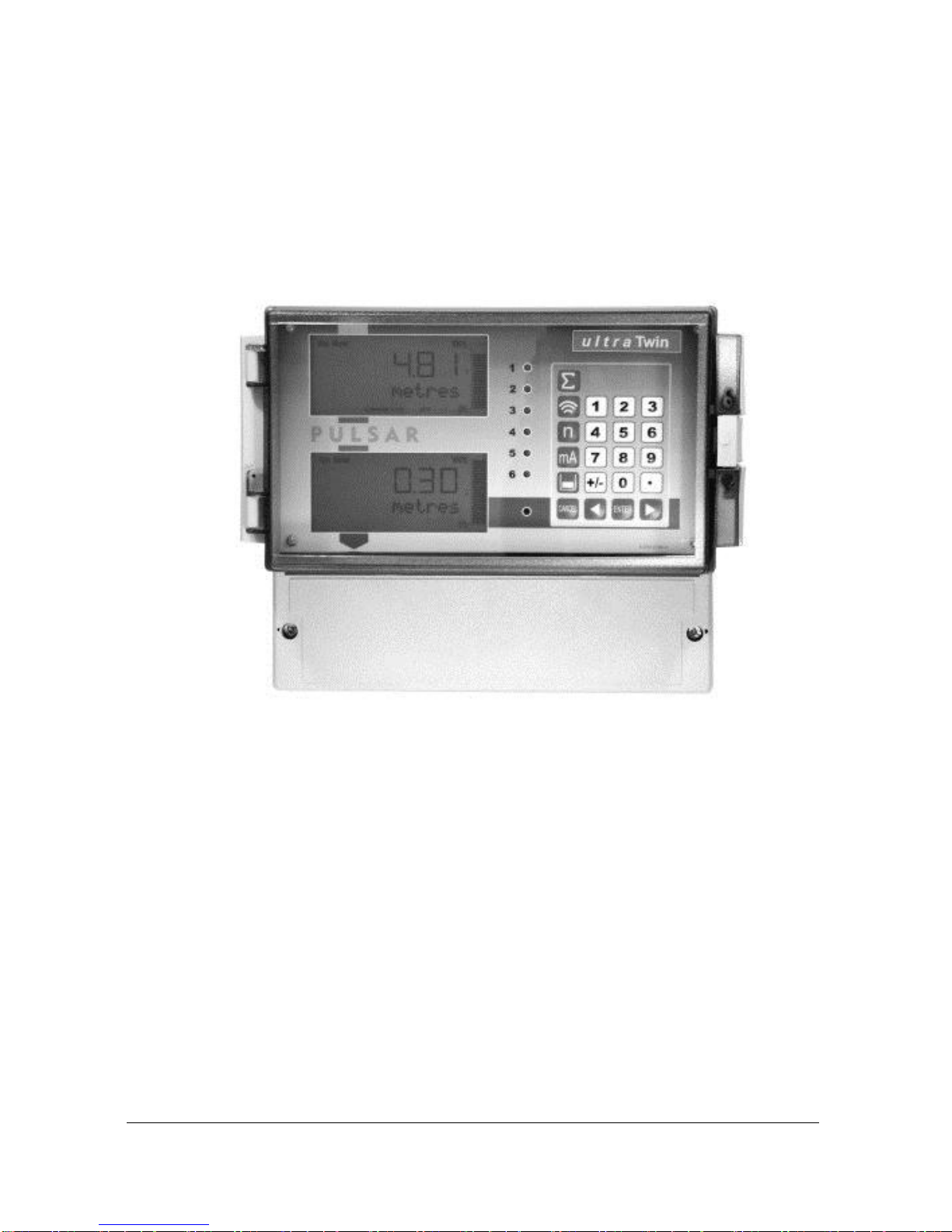
Ultra Twin has two independent points of measurement, the wallmount
model provides a dedicated display to each point of measurement, whilst the
fascia model, whilst in RUN, will show detail of one point of measurement
in the main display line, with the second point being displayed on the
auxillary display line. In both models the display will provide information
relevant to the point of measurement selected whilst in RUN and
PROGRAM mode.
Ultra Twin combines premium specification with high performance in a
most versatile system which is quickly configurable offering a choice of
applications in any combination, between the two points of measurement, of
three specific applications i.e. level or volume measurement, pump control
or flow measurement.
Functional Description
Ultra Twin sends a transmit pulse to the transducer(s), which emits an
ultrasonic pulse perpendicular to the transducer face, and the returned echo
is sent back to the Ultra Twin. The time taken to receive the echo is
measured and the distance from the transducer face to the surface being
monitored is calculated.

Page 3
Ultra Twin can measure from zero to 131 feet (40m) from the transducer to
the surface being monitored, dependent on the application chosen and
transducer used.
Six user-definable relays can be programmed to activate alarms, pump
starters, or other control equipment, and can be allocated to either point of
measurement. Also provided are four user definable digital inputs on the
wallmount model and seven on the fascia mount model, which can be
allocated to either point of measurement. There is an isolated 4-20 mA
output for each point of measurement that can be connected to a recorder or
PLC, to monitor level space, distance, volume, OCM head or flow
(dependant on the application chosen), independently from that shown on
the display. There is an RS232 port, so that the Ultra Twin can be operated
remotely by a PC or other equipment.
Ultra Twin can be programmed either by the built-in keypad (standard), or
by PC via the RS 232 Serial Interface (optional).
All parameters are stored in non-volatile memory, so are retained in the
event of power interruption. A second backup copy of all parameters can
also be retained in the Ultra Twin memory, in case an alternative set of
parameters needs to be stored.
The system utilises the unique DATEM software (Digital Adaptive
Tracking of Echo Movement). This is a proven digital mapping technique
developed especially for the Pulsar Ultra range, which gives the system
unequalled ability when identifying the “true target level” in the face of
competing echoes from pipes, pumps or other obstructions. Coupled with
the powerful, long-range abilities of the ‘all new’ dB transducer range, the
Ultra Twin lives up to its reputation as the most reliable ultrasonic level
measurement system available.
The Pulsar Ultra Twin ultrasonic level controller has been designed to
provide maintenance-free fit and forget performance.

Page 4
Product Specification
Physical
Wall Mount
Overall Outside dimensions 9.25 x 7.24 x 4.72 inch
(235 x 184 x 120 mm)
Weight Nominal 2.2lbs (1 kg)
Enclosure material/description Polycarbonate, flame resistant to
UL94-5V
Cable entry detail 10 cable entry knock outs, 5 x M20,
1 x M16 underside
4 x PG11 at rear
Fascia Mount
Outside dimensions 7.87 x 4.41 x 4.25 inch
(200 x 112 x 108 mm)
Weight Nominal 2.8lbs (1.3kg)
Enclosure material/description Stainless Steel back, Polycarbonate
UL94-V0 front and bezel
Transducer cable extensions 3-conductor 20AWG screened
Maximum separation 3,280 ft (1000 metres)
Environmental
Mounting - Wall Mount Indoor/Outdoor
- Fascia Mount Indoor
Relative Humidity (IP Rating)
- Wall Mount IP65 (NEMA 4X) when closed IP20
when open
- Fascia Mount (IP64 from front of panel) <35oC
(95oF) at 93% relative humidity
Pollution Degree 2
Altitude 2000m maximum
Max. & min. temperature (electronics) -4oF to 120oF (-20 ºC to +50 ºC)
Flammable atmosphere approval Safe area: compatible with approved
dB transducers (see transducer spec'
sheet)
Approvals
UL Certificate Number E257330
CE approval See EC Declaration of Conformity
Performance
Accuracy 0.25% of the measured range or
0.24" (6 mm) (whichever is greater)
Resolution 0.1% of the measured range or 0.08"
(2 mm) (whichever is greater)
Max. range Dependant on application and
transducer (maximum 131ft (40m)
dB40)
Min. range Dependent upon application and
transducer (minimum zero dB Mach3)
Rate response fully adjustable

Page 5
Echo Processing
Description DATEM (Digital Adaptive Tracking of
Echo Movement)
Outputs (x2)
Analogue output Isolated (floating) output (to 150V) of
4-20 mA or 0-20 mA into 500 (user
programmable and adjustable) 0.1%
resolution
Digital output Full Duplex RS232
Volt free contacts, number and rating 6 form "C" (SPDT) rated at 5A at 115V
AC
Digital Inputs
Wall Mount x4 Min. Input Voltage 4.5VDC
Fascia Mount x7 Max. Input Voltage 30VDC (Max Current
3mA)
24VDC Input Supply maximum total
current 24mA.
Displays
Wallmount x2 6 digits plus 12 character text, plus
Fascia Mount x1 bargraph with direction indicators,
remote communicator identifier, and
program/run/test mode indicators
Programming
On-board programming By integral keypad
PC programming via RS232
Programming security Via passcode (user selectable and
adjustable)
Programmed data integrity Via non-volatile RAM, plus backup
Supply
Power supply 115V AC + 5% / -10% 50/60 Hz,
dc 18 - 30V (If using a battery then
24V minimum 1AH, dependant on life
required, externally fused with 1A fast
blow fuse.
10W maximum power (typically 6W)
Overvoltage Category II
Fuses
Mains (F1) 125 mA T at 115 VAC
DC (Battery) (F2) 1A Thermal (self resetting after power
removed). Not user replaceable
Transducer (F3, F5 Ch.1 & F4, F6 Ch. 2) Littelfuse 242 series 100mA Part No.
0242.100. This fuse is not user
replaceable and has a 4000A breaking
capability to comply with certification
of the Exm version of dB series
transducers.
Pulsar Process Measurement Limited operates a policy of constant development and
improvement and reserve the right to amend technical details as necessary.
Page 6
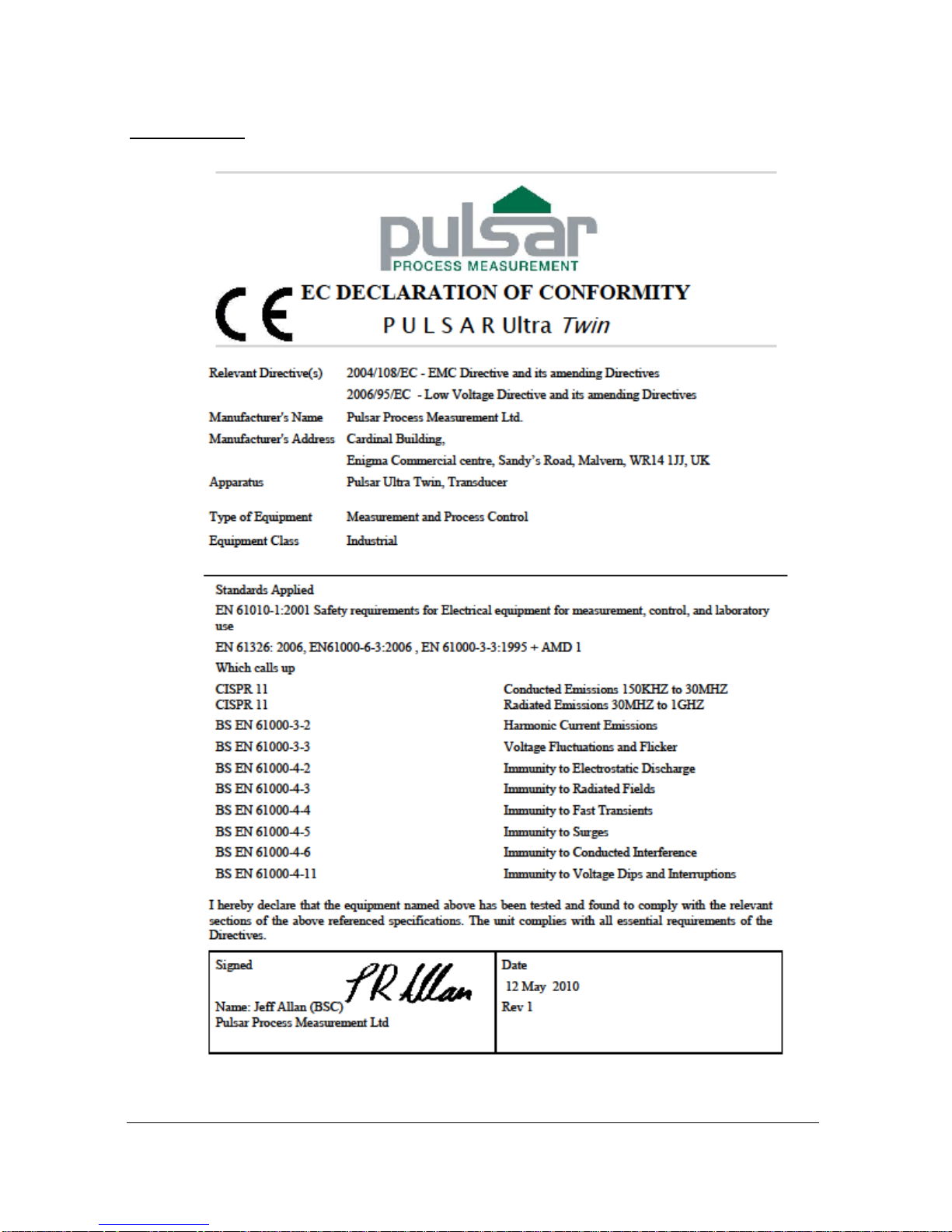
EC Declaration of Conformity
Wall Mount
Page 7
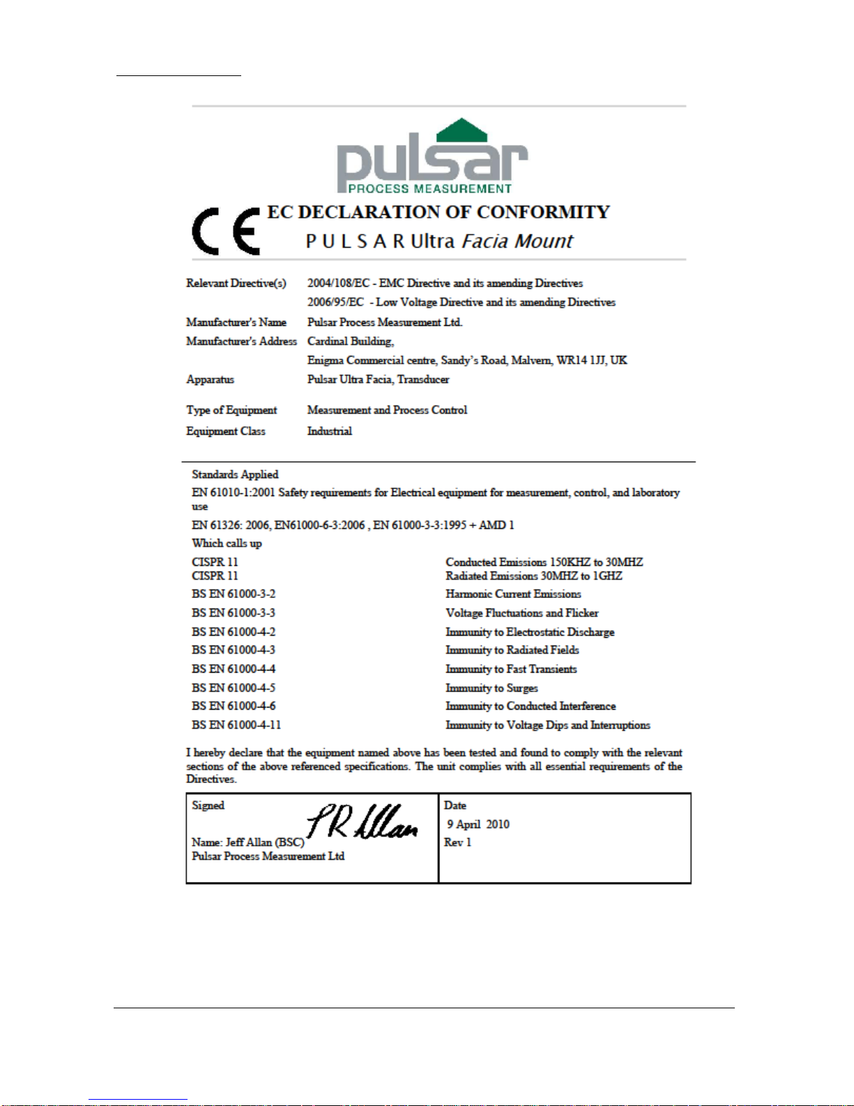
Fascia Mount

Page 8
This page left blank intentionally
Page 9
Chapter 2 Installation
Power Supply Requirements
The Ultra Twin can operate from AC supply or from a DC battery and is
designed for use in temperatures between -4oF to +140oF (-20oC to +50oC).
The AC is 115 +5% / -10% 50/60Hz. The DC is 18-30V. In all cases the
Ultra Twin will typically consume 6W of power, with a maximum of 10W.
If Ultra Twin has both an AC and DC supply available then the AC supply
source will be automatically sensed and used, should the AC supply be
removed for any reason then the DC supply will take over.
The AC and DC wiring should be completed using either 16 – 14AWG
(1.5–2.5mm2) stranded or 16 – 14AWG (1.5–4mm2) solid wire, with all
terminals being tightened to 4.5in. lbs. (0.5Nm).
An external supply isolator/circuit breaker (AC or DC) must be fitted near to
the unit and labelled to identify the instrument to which it refers.
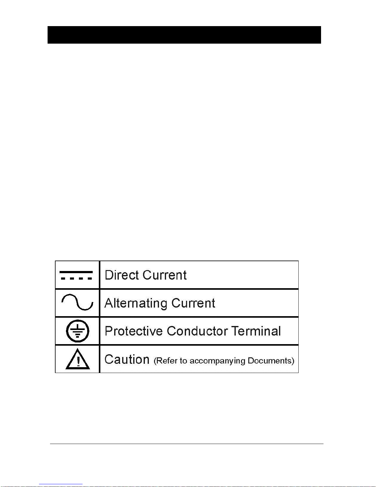
Safety Symbols
Detailed below are descriptions and meanings of safety/warning symbols
that are used on the Ultra Twin and in this manual.
Page 10
Location
All electronic products are susceptible to electrostatic
shock, so follow proper grounding procedures during
installation.
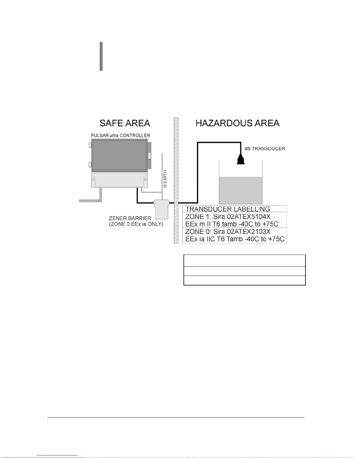
Ultra Twin must be mounted in a non-hazardous (safe) area, and the
transducer fitted in the hazardous area.
When choosing a location to mount the enclosure, bear in mind the following:
Ensure that the Ultra Twin is installed in a “Safe”, non-hazardous,
area.
For a clear view of the LCD display it is recommended that it is
mounted at eye level.
The mounting surface is vibration-free.
The ambient temperature is between -4oF and 140oF (-20ºC and
50ºC).
There should be no high voltage cables or inverters close by.
FM APPROVED TRANSDUCERS
Class I, Div. 1, Group A, B, C & D
Class II, Div. 1, Group E, F & G
Page 11
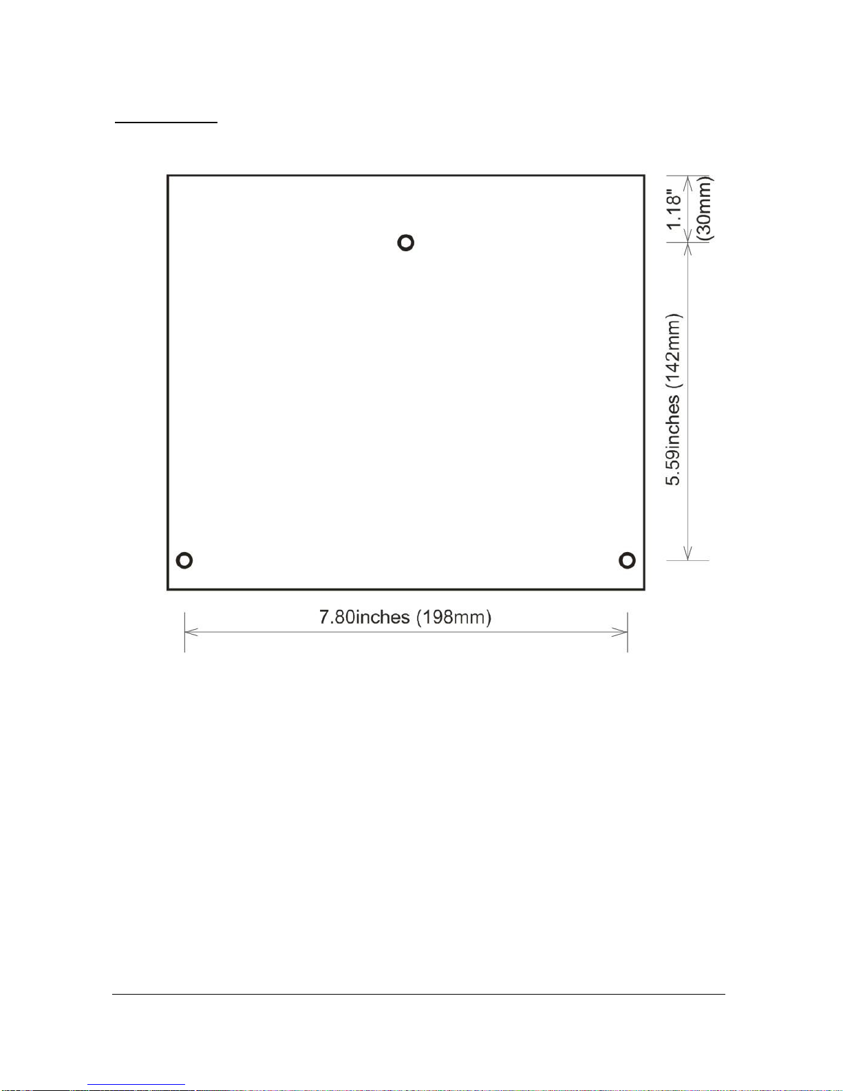
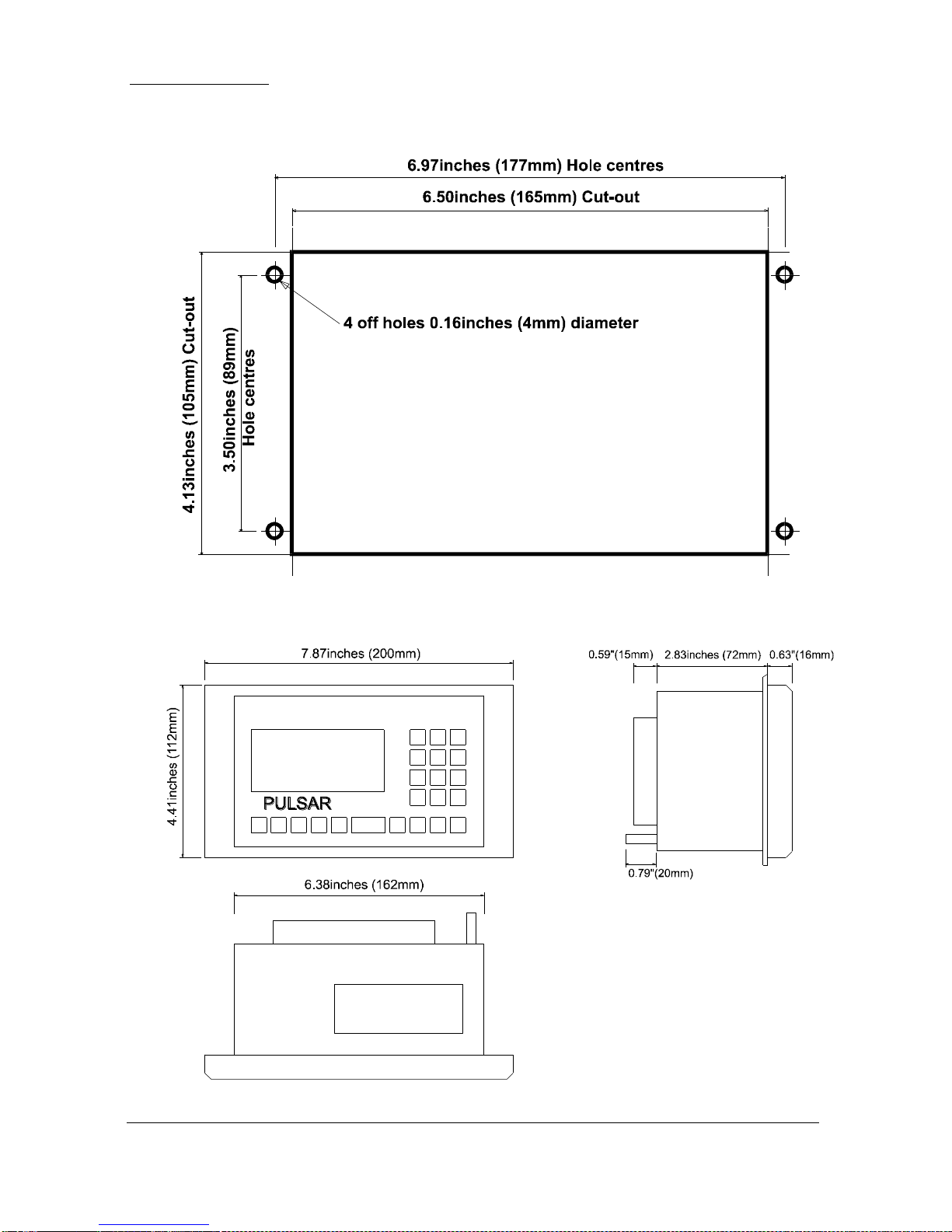
Dimensions
Wall mount
The dimensions of the wall fixing holes are as shown below.
The Ultra Twin should be mounted by drilling three holes suitable for size 8
screws (length to suit your application), and fixing the top screw in place.
Hang the unit on this and fix the two remaining screws by removing the
terminals access cover to access the pre drilled holes.
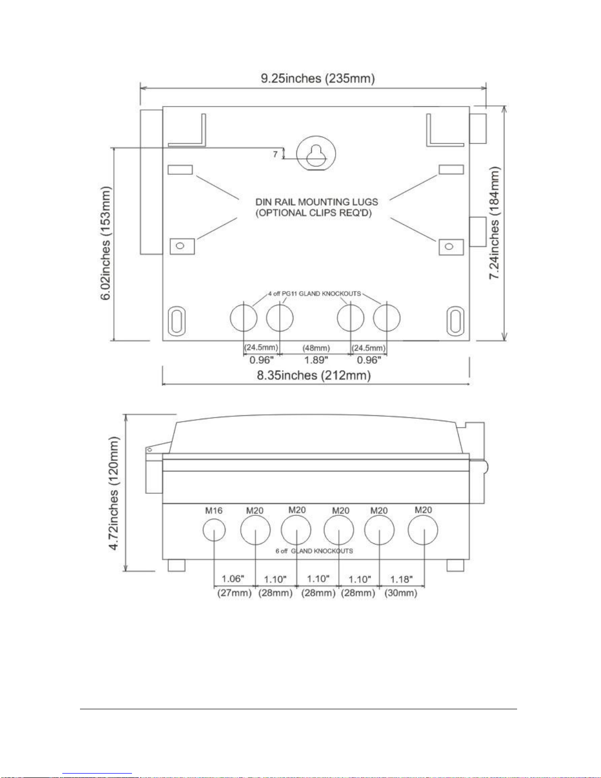
Page 12
The full dimensions of the enclosure are as shown below
.

Page 13
Cable Entry
There are 6 cable gland knock-outs on the base of the wall mount Ultra
Twin (5 x 0.79" (20mm), 1 x 0.63" (16mm)) and 4 on the rear (4 x 0.73"
(18mm)). Select which ones you wish to use, and remove them by using a
circular cutter, such as a tank cutter. Take care not to damage the circuit
board inside while undertaking this. Do not use a hammer, as this may cause
damage to the enclosure.
It is recommended that you use suitable cable glands to ensure that the
ingress rating is maintained and that they be tightened to the manufacturers
recommended settings.
Important Information
All cable glands should be tightened to the manufacturer’s specifications.
The terminal compartment cover screws should be tightened to 1.48lb
in.(2Nm)
Care should be taken not to over tighten the screws.
Page 14
Fascia Mount
The Fascia mount Ultra Twin should be installed by cutting a hole in the
panel, as detailed below, and securing the unit with the fixings supplied.
The full dimensions of the Fascia mount enclosure are as shown below.
Page 15
Important Information
When mounting the fascia mount unit in to a panel, in order to
maintain the panel IP rating the panel should be of smooth/painted
finish and be machined, as per the details contained in this manual.
Fit the unit through the hole then, using the components supplied
place a plain washer then a spring washer followed by an elongated
nut to each of the 4 off M3 threaded studs and tighten to 2.5lb in.
(0.28Nm)
Care should be taken not to overtighten the screws.
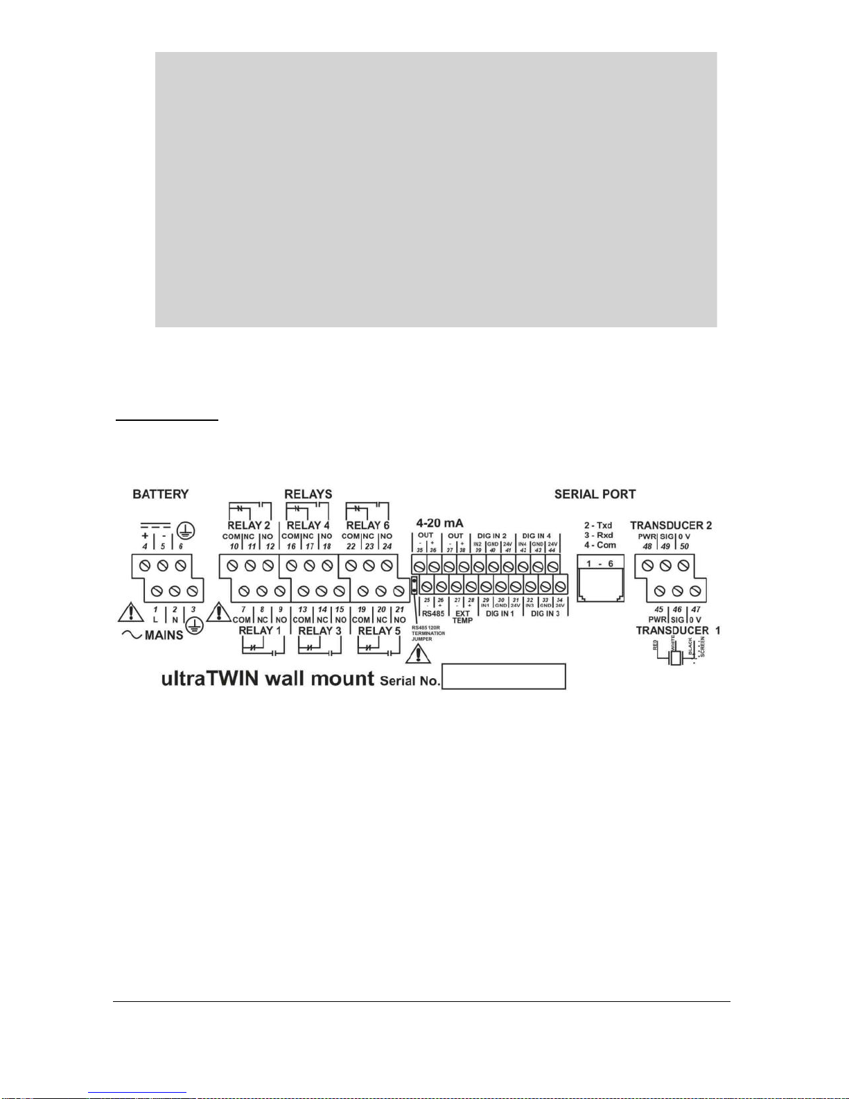
Terminal Connection Details
Wall Mount
The terminal strip is as detailed below. There is also a wiring diagram inside
the terminals access cover.
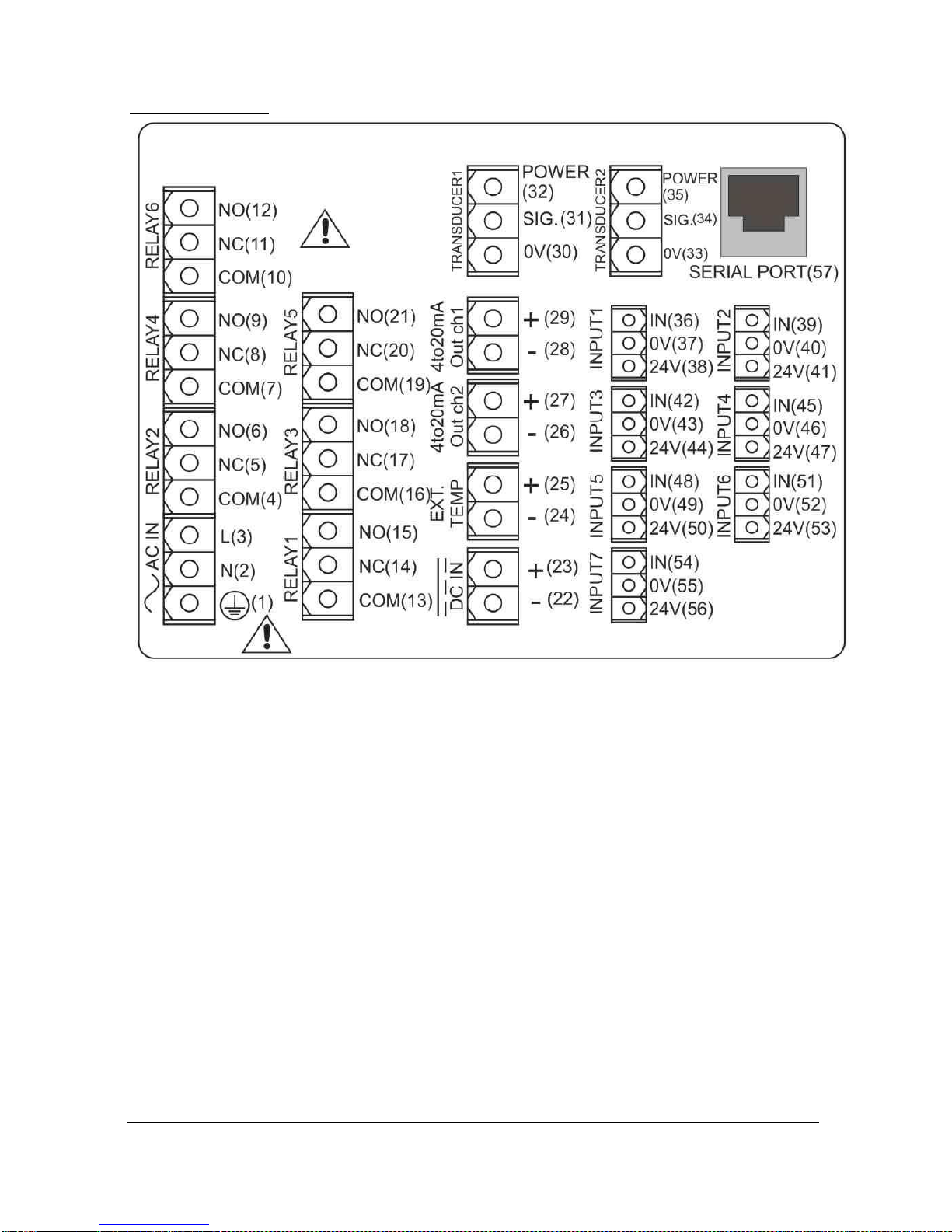
Page 16
Fascia Mount

Page 17
Terminal Connections
Important Information
All terminal connection screws should be tightened to 4.5in.lbs.
(0.5Nm).
Care should be taken not to overtighten the screws.
Power
The Ultra Twin can operate from mains AC and automatically from DC or
battery backup in the event of power failure, or can be operated permanently
from DC or batteries.
Important Information
The protective earth must be connected prior to any other cabling
taking place. This is connected to terminal 3, on all wall mount
units, and should be tightened to 4.5in.lbs. (0.5Nm). In the case of
the fascia unit the earth should be connected to the stud at the rear of
the enclosure and tightened to 7.4lbF (10Nm).
The AC and DC wiring should be completed using either 16 – 14AWG
(1.5–2.5mm2) stranded or 16 – 14AWG (1.5–4mm2) solid wire.
An external supply isolator/circuit breaker (AC or DC) must be fitted near to
the unit and labelled to identify the instrument to which it refers.

Page 18
Transducer
The transducer should be installed, and connected, in accordance with the
installation instructions contained in the Transducer User Guide.
The entire range of, standard dB transducers are certified for use in
hazardous areas and different models, for each, are available for use in Zone
1 or Zone 0.
Wire the transducer to the Ultra Twin’s transducer terminals, terminal
numbers will depend on the unit type, as follows:
Transducer 1
Terminal Connection Details
Unit Type
Red
Power
White
Signal
Black
0 volts
Green
Screen
Wall Mount
45
46
47
47
Fascia Mount
32
31
30
30
Transducer 2
Terminal Connection Details
Unit Type
Red
Power
White
Signal
Black
0 volts
Green
Screen
Wall Mount
48
49
50
50
Fascia Mount
35
34
33
33
If splicing, it is recommended using a junction box with standard twisted,
shielded pair at 20 AWG.
When using 2-core screened extension cable, the Black and Green wires of
the transducer should be connected to the screen of the extension cable,
which in turn should be connected to the relevant 0 volts terminal.

Page 19
When installing a transducer in a hazardous area use an approved
transducer, from the Pulsar dB range, suitable for the proposed application.
FM
For EEx m (Zone 1) applications a transducer certified to FM Class I Div 1
Group A, B, C & D, ClassII Div 1 Group E, F & G, Class III is used, and
must be supplied via a 1500A breaking fuse, which is fitted as standard to
the blackbox level controller.
Restrictions do not use in the presence of these groups of Chemicals,
Aliphatic Hydro Carbons, Ketones or Esters
For EEx ia (I.S.) a transducer certified to FM Class I Div 1 Group A, B, C
& D, ClassII Div 1 Group E, F & G is used, which must be connected to
the blackbox via an external Zener barrier.
ATEX
For EEx m (Zone 1) applications a transducer certified to Sira
02ATEX5104X is used, and must be supplied via a 4000A breaking fuse,
which is fitted as standard to the blackbox level controller.
For EEx ia (Zone 0) a transducer certified to Sira 02ATEX2103X is used,
which must be connected to the blackbox via an external Zener barrier.
See transducer label for certification details.

Page 20
Important Information
Please note that if the output of the ultrasonic transducers used with
the Ultra Twin are capable of emitting sound pressure levels in excess
of 85dBA (above a reference sound pressure level of 20µPA), then the
Ultra Twin must be located remote from the transducer such that a
sound pressure level of 85dBA is not exceeded when standing at the
Ultra Twin in the operators position.
Important Information
When using the Ultra Twin to measure the differential level
between the two points of measurement then transducer one must
be located on the upstream side of the application.
Relay Outputs
The six relays can be programmed for a variety of alarms, pump control, or
other process functions and allocated to either point of measurement. The
relay contacts are all rated at 5A at 115V AC.
Wiring should be completed by using suitable cable, to meet the specified
115V AC 5A contact rating, up to maximum size of 14AWG.
All connections should be such that the short circuit capacity of the circuits
to which they are connected, is limited by fuses rated so that they do not
exceed the relay rating.
Digital Inputs
Where the Ultra Twin is required to provide power for a Device Input the
appropriate Digital Input should be wired between the 24VDC supply
terminal and the IN terminal. (TOTAL maximum current available, for all
digital inputs, four on Wall Mount model and seven on Fascia Mount model,
from the 24VDC supply is 24mA). When Device Inputs are self powered,
connection of the device should be made between the Common terminal and
the IN terminal. (Minimum Input voltage 4.5VDC, Maximum Input voltage
30VDC with a maximum current of 3mA).
Current Output
There are two mA Outputs which are fully assignable, both outputs are an
isolated (floating) mA output, of 4 - 20mA or 0 - 20mA, and the load should
not exceed 500.
Page 21
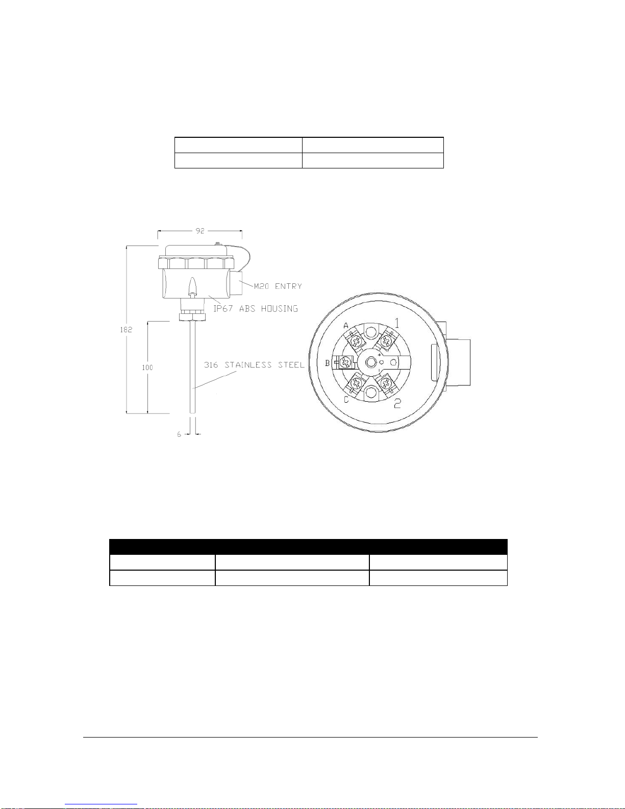
Temperature Input
The external temperature sensor allows more localised compensation of the
measured distance due to changes in temperature.
There are two models, Type A and Type B as follows:
Type A
-25ºC to 50ºC
Type B
-25ºC to 125ºC
The temperature sensor should be placed close to the point of measurement.
The unit is connected as follows:
Description
Temperature Sensor
Ultra Twin
Power Supply
Terminal 1
Terminal 27
Return
Terminal 2
Terminal 28
Temp Source (P1-852, P2-852), should be set to option 4 or 5 depending on
the sensor range, set 4 for type A and 5 for type B (see above), the range is
specified on the label of the sensor.
RS232 Serial Interface
If required, you can connect to the serial interface, to operate your Ultra
Twin remotely.
Page 22
Fuse Location
Wall mount
The mains fuse is located, inside the terminal compartment, to the left of
the mains terminals, as illustrated below.
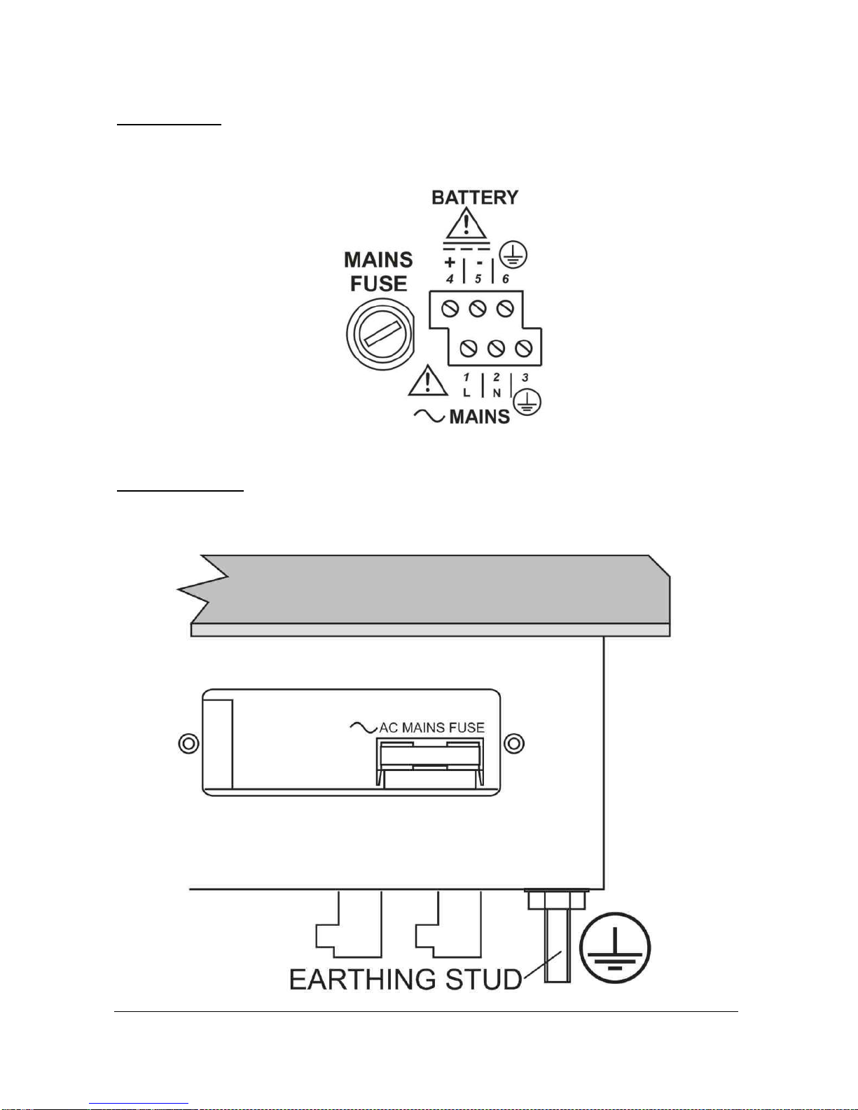
Fascia mount
The mains fuse is located under the removable cover at the bottom of the
unit, as illustrated below.
 Loading...