

Page 1
ULTRA 5
INSTRUCTION MANUAL
Page 2

Page 3

ULTRA 5 (FOURTH EDITION)
June 2017
Part Number M-180-5-003P
COPYRIGHT
© Pulsar Process Measurement Limited, 2005 -17. All rights reserved. No part of this publication may
be reproduced, transmitted, transcribed, stored in a retrieval system, or translated into any language in
any form without the written permission of Pulsar Process Measurement Limited.
WARRANTY AND LIABILITY
Pulsar Process Measurement Limited guarantee for a period of 2 years from the date of delivery that it
will either exchange or repair any part of this product returned to Pulsar Process Measurement
Limited if it is found to be defective in material or workmanship, subject to the defect not being due to
unfair wear and tear, misuse, modification or alteration, accident, misapplication or negligence.
DISCLAIMER
Pulsar Process Measurement Limited gives nor implies any process guarantee for this product, and
shall have no liability in respect of any loss, injury or damage whatsoever arising out of the
application or use of any product or circuit described herein.
Every effort has been made to ensure accuracy of this documentation, but Pulsar Process
Measurement Limited cannot be held liable for any errors.
Pulsar Process Measurement Limited operates a policy of constant development and improvement and
reserves the right to amend technical details as necessary.
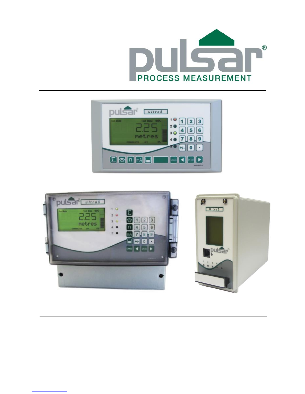
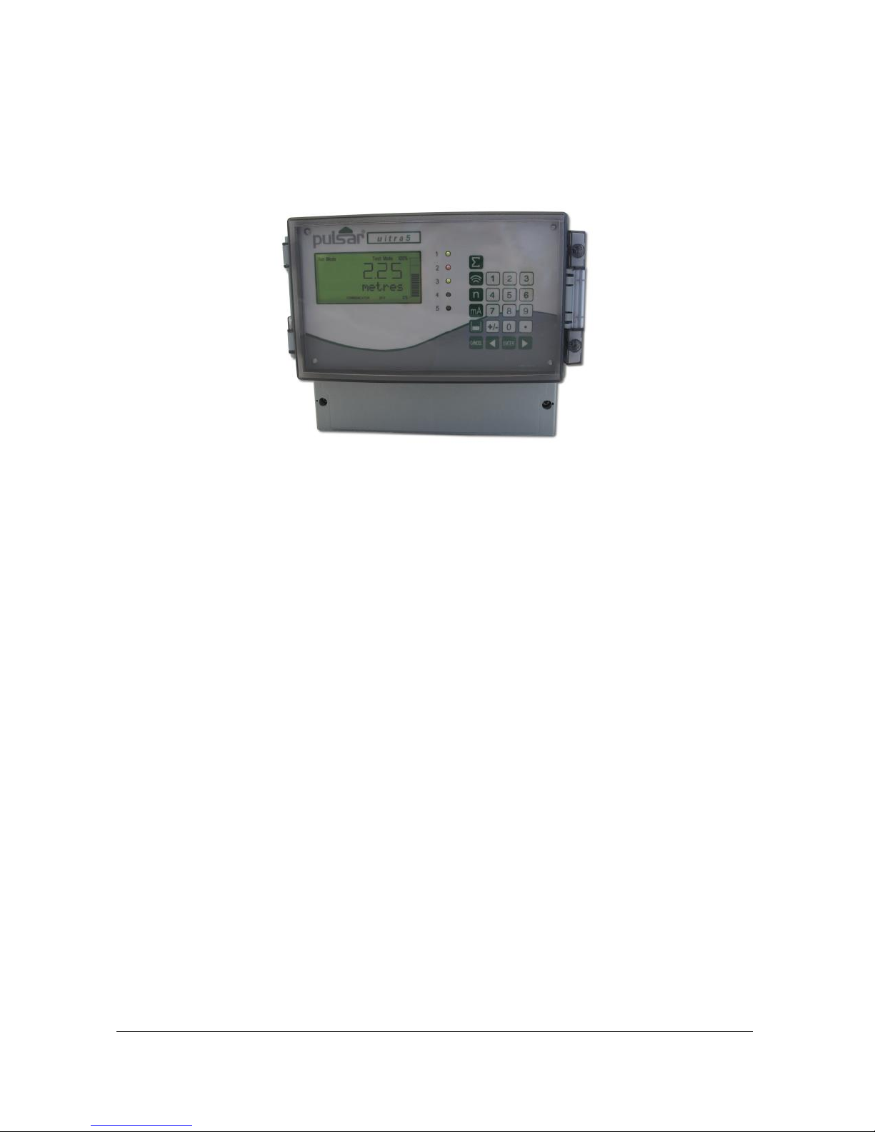
The Ultra 5 units shown on the cover of this manual is used for illustrative purposes only and may not
be representative of the actual Ultra 5 unit supplied.
TECHNICAL ENQUIRIES
Please contact Pulsar Process Measurement Limited for technical support.
COMMENTS AND SUGGESTIONS
If you have any comments or suggestions about this product, then please contact:
Pulsar Process Measurement Limited
Pulsar Process Measurement Inc.
Cardinal Building
Enigma Business Centre
Sandy’s Road
Malvern
Worcestershire
WR14 1JJ
United Kingdom
PO Box 5177
Niceville
FL 32578 - 5177
USA
Tel: + 44 (0) 1684 891371
Fax: + 44 (0) 1684 575985
Tel: + 1 850 279 4882
Fax: + 1 850 279 4886
Web Site: http://www.pulsar-pm.com
e-mail: info@pulsar-pm.com (general
information)
e-mail: support@ pulsar-pm.com (product
support)
Web Site: http://www.pulsar-pm.com
e-mail: info.usa@pulsar-pm.com (general
information)
e-mail: support.usa@ pulsar-pm.com (product
support)
Page 4

Page 5

Contents
Chapter 1 Start Here… ......................................................................................................................................... 1
About this Manual ................................................................................................................................................... 1
About the Ultra 5 ..................................................................................................................................................... 2
Functional Description ............................................................................................................................................ 3
How to use this Manual .......................................................................................................................................... 4
Product Specification .............................................................................................................................................. 5
EU Declaration of Conformity ............................................................................................................................... 7
Wall Mount ..................................................................................................................................................... 7
Fascia Mount ................................................................................................................................................... 8
Rack and Panel ................................................................................................................................................ 9
Chapter 2 Installation.......................................................................................................................................... 11
Power Supply Requirements ................................................................................................................................ 11
Location ................................................................................................................................................................. 11
Dimensions ............................................................................................................................................................ 12
Wall mount .................................................................................................................................................... 12
Fascia Mount ................................................................................................................................................. 14
Rack ad Panel ................................................................................................................................................ 16
Terminal Connection Details ................................................................................................................................ 18
Wall Mount ................................................................................................................................................... 18
Fascia Mount ................................................................................................................................................. 18
Rack and Panel .............................................................................................................................................. 19
Voltage Selector and Fuse Location ..................................................................................................................... 23
Wall mount .................................................................................................................................................... 23
Fascia mount ................................................................................................................................................. 23
Rack and Panel mount .................................................................................................................................. 24
Preparation for Operation ...................................................................................................................................... 26
Maintenance .......................................................................................................................................................... 26
Chapter 3 How To Use Your Ultra 5 ................................................................................................................ 28
Operating the Controls .......................................................................................................................................... 28
Display ........................................................................................................................................................... 28
Run Mode ...................................................................................................................................................... 29
Program Mode .............................................................................................................................................. 30
How to Access Program Mode ............................................................................................................................. 30
Wall and Fascia mount ................................................................................................................................. 30
Rack and Panel .............................................................................................................................................. 30
Test Mode .............................................................................................................................................................. 36
Using the RS232 Serial Interface.......................................................................................................................... 37
Parameter Defaults ................................................................................................................................................ 39
Factory Defaults ............................................................................................................................................ 39
Chapter 4 Ultra Wizard ........................................................................................................................................... 40
Ultra Wizard Menu ............................................................................................................................................... 40
Lev/Vol .................................................................................................................................................................. 41
Level Star 5 ................................................................................................................................................... 41
Pump/Diff .............................................................................................................................................................. 42
Advanced 5 .................................................................................................................................................... 42
Flow ....................................................................................................................................................................... 42
Flow 5 ............................................................................................................................................................ 43
Chapter 5 Level / Volume .................................................................................................................................. 44
Quick Setup Menu................................................................................................................................................. 46
Page 6

Example 1 Level Monitoring with Alarms .................................................................................................. 51
Example 2 Level Monitoring and Control (up or down) ............................................................................ 53
Example 3 Volume Application ................................................................................................................... 55
Menu System and Parameter Guide ..................................................................................................................... 58
Top Level Menu ............................................................................................................................................ 58
Application Menu ......................................................................................................................................... 59
Relays Menu ................................................................................................................................................. 60
Data Logs Menu ............................................................................................................................................ 61
Volume Menu ............................................................................................................................................... 62
Display Menu ................................................................................................................................................ 63
mA Output Menu .......................................................................................................................................... 64
Compensation Menu ..................................................................................................................................... 64
Stability Menu ............................................................................................................................................... 65
Echo Processing Menu ................................................................................................................................. 66
System Menu ................................................................................................................................................ 67
Device Comm Menu .................................................................................................................................... 68
Test Menu ...................................................................................................................................................... 69
Chapter 6 Pump .................................................................................................................................................. 70
Quick Setup Menu................................................................................................................................................. 72
Example 1 Level Monitoring with Alarms .................................................................................................. 78
Example 2 Sump Control (pump down) ...................................................................................................... 80
Example 3 Reservoir Control (pump up) ..................................................................................................... 82
Example 4 Differential Control .................................................................................................................... 84
Menu System and Parameter Guide ..................................................................................................................... 86
Top Level Menu ............................................................................................................................................ 86
Application Menu ......................................................................................................................................... 87
Relays Menu ................................................................................................................................................. 88
Pump “Advanced” Menu ............................................................................................................................. 89
Data Logs Menu ............................................................................................................................................ 90
Pumped Volume Menu................................................................................................................................. 91
Efficiency Menu ............................................................................................................................................ 92
Display Menu ................................................................................................................................................ 93
mA Output Menu .......................................................................................................................................... 94
Compensation Menu ..................................................................................................................................... 94
Stability Menu ............................................................................................................................................... 95
Echo Processing Menu ................................................................................................................................. 96
System Menu ................................................................................................................................................ 97
Device Comm Menu .................................................................................................................................... 97
Test Menu ...................................................................................................................................................... 99
Chapter 7 Flow.................................................................................................................................................. 100
Quick Setup Menu............................................................................................................................................... 103
Exponential Devices ............................................................................................................................................ 107
Point of Measurement ................................................................................................................................. 108
Calculations ................................................................................................................................................. 110
Example 1 ‘V’ Notch Weir....................................................................................................................... 112
BS3680 Flumes ................................................................................................................................................... 114
Point of Measurement ................................................................................................................................. 114
Calculations ................................................................................................................................................. 115
Example 2 BS3680 U-Throated Flume .................................................................................................... 117
BS3680 Thin Plate Weirs.................................................................................................................................... 119
Point of Measurement ................................................................................................................................. 119
Calculations ................................................................................................................................................. 119
Example 3 BS3680 Rectangular Weir ....................................................................................................... 121
BS3680 Rectangular Broad Crested Weir ......................................................................................................... 123
Point of Measurement ................................................................................................................................. 123
Calculations ................................................................................................................................................. 123
Page 7

Velocity Area ....................................................................................................................................................... 125
Point of Measurement ................................................................................................................................. 125
Calculations ................................................................................................................................................. 126
Special Devices ................................................................................................................................................... 129
Point of Measurement ................................................................................................................................. 129
Calculations ................................................................................................................................................. 130
Universal Calculations ........................................................................................................................................ 131
Point of Measurement ................................................................................................................................. 131
Calculations ................................................................................................................................................. 131
Menu System and Parameter Guide ................................................................................................................... 132
Top Level Menu .......................................................................................................................................... 132
Application Menu ....................................................................................................................................... 133
Relays Menu ............................................................................................................................................... 134
Data Logs Menu .......................................................................................................................................... 135
OCM ............................................................................................................................................................ 136
Display Menu .............................................................................................................................................. 137
mA Output Menu ........................................................................................................................................ 137
Compensation Menu ................................................................................................................................... 138
Stability Menu ............................................................................................................................................. 138
Echo Processing Menu ............................................................................................................................... 139
System Menu .............................................................................................................................................. 140
Device Comm Menu .................................................................................................................................. 141
Test Menu .................................................................................................................................................... 142
Chapter 8 Parameter Listing and Descriptions .................................................................................................... 144
Application Parameters ....................................................................................................................................... 144
Operation ..................................................................................................................................................... 144
Dimensions .................................................................................................................................................. 146
mA Input ..................................................................................................................................................... 148
Relay Parameters ................................................................................................................................................. 150
Alarms ......................................................................................................................................................... 152
General Control ........................................................................................................................................... 156
Pumps .......................................................................................................................................................... 157
Control ......................................................................................................................................................... 162
Miscellaneous .............................................................................................................................................. 169
Pump by Time ............................................................................................................................................. 171
Common Parameters .................................................................................................................................. 174
Pump “Advanced” Parameters ........................................................................................................................... 175
Pump Run On .............................................................................................................................................. 175
Starting ......................................................................................................................................................... 175
Stopping ....................................................................................................................................................... 176
Pump Exercising ......................................................................................................................................... 176
Wall Cling ................................................................................................................................................... 177
Storm ........................................................................................................................................................... 177
Data Log Parameters ........................................................................................................................................... 178
Totaliser Audits ........................................................................................................................................... 178
Temperature ................................................................................................................................................ 178
Pump Logs .................................................................................................................................................. 180
Pumped Volume .................................................................................................................................................. 181
Set Up .......................................................................................................................................................... 181
Volume ................................................................................................................................................................ 182
Conversion .................................................................................................................................................. 182
Breakpoints .................................................................................................................................................. 185
Tables........................................................................................................................................................... 187
Pump Efficiency .................................................................................................................................................. 187
Set Up .......................................................................................................................................................... 187
Page 8

OCM Parameters ................................................................................................................................................. 190
PMD Setup .................................................................................................................................................. 190
Dimensions .................................................................................................................................................. 194
Calculations ................................................................................................................................................. 197
Velocity ....................................................................................................................................................... 198
Breakpoints .................................................................................................................................................. 199
Tables........................................................................................................................................................... 199
Average Flow .............................................................................................................................................. 200
Display Parameters .............................................................................................................................................. 200
Options ........................................................................................................................................................ 200
Failsafe ......................................................................................................................................................... 201
Auxiliary ...................................................................................................................................................... 202
Totaliser ....................................................................................................................................................... 204
Bargraph ...................................................................................................................................................... 206
mA Output Parameters ........................................................................................................................................ 207
Range ........................................................................................................................................................... 207
Operation ..................................................................................................................................................... 207
Setpoint ........................................................................................................................................................ 208
Limits ........................................................................................................................................................... 208
Trim ............................................................................................................................................................. 209
Failsafe ......................................................................................................................................................... 209
Allocation .................................................................................................................................................... 210
Compensation Parameters................................................................................................................................... 210
Offset ........................................................................................................................................................... 210
Temperature ................................................................................................................................................ 211
Velocity ....................................................................................................................................................... 212
Stability Parameters ............................................................................................................................................. 213
Damping ...................................................................................................................................................... 213
Indicator ....................................................................................................................................................... 213
Rate .............................................................................................................................................................. 213
Filters ........................................................................................................................................................... 214
Echo Processing Parameters ............................................................................................................................... 215
Transducer 1 Status ..................................................................................................................................... 215
Transducer 2 Status ..................................................................................................................................... 216
System Parameters .............................................................................................................................................. 217
Passcode ...................................................................................................................................................... 217
Backup ......................................................................................................................................................... 217
System Information ..................................................................................................................................... 217
Date & Time ................................................................................................................................................ 218
LED Colour ................................................................................................................................................. 219
Watchdog .................................................................................................................................................... 220
Daylight Saving Time ................................................................................................................................. 220
Service Alarm.............................................................................................................................................. 224
Device Comm. ..................................................................................................................................................... 225
RS232 Set Up .............................................................................................................................................. 225
RS 485 Set Up ............................................................................................................................................. 225
Remote Alarm ............................................................................................................................................. 225
Test Parameters ................................................................................................................................................... 228
Simulation ................................................................................................................................................... 228
Hardware ..................................................................................................................................................... 229
Chapter 9 Troubleshooting .............................................................................................................................. 231
Parameter Record .................................................................................................................................................. 233
Page 9

Page 1
Chapter 1 Start Here…
Congratulations on your purchase of a Pulsar Ultra 5. This quality system
has been developed over many years and represents the latest in high
technology ultrasonic level measurement and control.
It has been designed to give you years of trouble free performance, and a
few minutes spent reading this operating manual will ensure that your
installation is as simple as possible.
About this Manual
It is important that this manual is referred to for correct installation
and operation.
There are various parts of the manual that offer additional help or
information as shown.
Tips
TIP
At various parts of this
manual you will find tips to
help you.
Additional Information
Additional Information
At various parts of the manual, you will find sections
like this that explain specific things in more detail.
References
See Also
References to other parts of the manual
Page 10
Page 2
About the
Ultra 5
Ultra 5 is a brand-new concept in ultrasonic level measurement. Within its
memory are all the functions and settings of three different and completely
separate ultrasonic devices.
The Ultra 5 does not offer a multiple range of functions blended together
which lead to complicated calibration and a compromise to the specification,
Ultra 5 is the first ever system to offer the ability to dedicate the
functionality of the unit to any of four specific duties i.e. level or volume
measurement, pump control, differential level or flow measurement.
The benefits are many but most importantly the unit provides:
1. A most versatile system which is quickly configurable to offer anyone
four separate functions within seconds. Ideal for simplicity of purchase
and off the shelf spares.
2. A totally dedicated device with the ability to perform all aspects of the
task required i.e. no compromise in specification.
3. Easy to set up using the unique “Quick Set Up” Menu. To calibrate, first
set the Ultra Wizard for the desired task, and then refer to the relevant
chapter in this manual that relates to your application:
Chapter 5 for Level or Volume,
Chapter 6 for Pump Control or Differential Level
Chapter 7 for Flow
Page 11

Page 3
Functional Description
Ultra 5 sends a transmit pulse to the transducer, which emits an ultrasonic
pulse perpendicular to the transducer face, and the returned echo is sent back
to the Ultra 5. The time taken to receive the echo is measured and the
distance from the transducer face to the surface being monitored is
calculated.
Ultra 5 can measure from zero to 40m from the face of the transducer to the
surface being monitored, dependent on the application chosen and
transducer used.
The relays can be programmed to activate alarms, pump starters, or other
control equipment. There is an isolated 4-20 mA output that can be
connected to a recorder or PLC, to monitor, depending on application
chosen, level space or distance, OCM head, OCM flow or volume,
independently from that shown on the display. There is an RS232 port, so
that the Ultra 5 can be operated remotely by a PC or other equipment.
Ultra 5 can be programmed either by the built-in keypad (standard on all
wall and fascia units), or by PC via the RS 232 Serial Interface (optional).
The optional rack and panel mounted units are programmed with the
“Remote Communicator”, and one Communicator can program many Pulsar
Ultra 5 units. All parameters are stored in non-volatile memory, so are
retained in the event of power interruption. A second backup copy of all
parameters can also be retained in the Ultra 5 memory, in case an alternative
set of parameters needs to be stored.
Five user definable control relays with individual setpoints and intelligent
performance logging software features ensure maximum control versatility.
The system utilises the unique DATEM software (Digital Adaptive
Tracking of Echo Movement). This is a proven digital mapping technique
developed especially for the Pulsar Ultra range, which gives the system
unequalled ability when identifying the “true target level” in the face of
competing echoes from pipes, pumps or other obstructions. Coupled with
the powerful, long-range abilities of the ‘all new’ dB transducer range, the
Ultra 5 lives up to its reputation as the most reliable ultrasonic level
measurement system available.
The Pulsar Ultra 5 ultrasonic level controller has been designed to provide
maintenance-free fit and forget performance.
Page 12

Page 4
How to use this Manual
1. Read the installation and operating instructions contained in, Chapters 2
and 3, carefully, they are applicable in every use of this product.
2. Decide which “task” you wish your Ultra 5 to perform for you and then
configure the unit using “Ultra Wizard” as described in Chapter 4.
3. Move directly to the appropriate chapter of this manual as listed below, for
details on how to program Ultra 5 using the “Quick Set Up” Menu.
Chapter
Function / Task
Chapter 5 Level/Volume
Measurement of Level or Volume
Chapter 6 Pump/Differential
Control of Pumps or Differential
measurement and Control
Chapter 7 Flow
Measurement of Open Channel Flow
Page 13

Page 5
Product Specification
Physical
Wall Mount
Outside dimensions 235 x 184 x 120 mm
Weight Nominal 1 kg
Enclosure material/description Polycarbonate, flame resistant to UL91
Cable entry detail 10 cable entry knock outs, 5 x M20, 1 x M16
underside,
4 x PG11 (18mm) at rear
Fascia Mount
Outside dimensions 200 x 112 x 108
Weight Nominal 1.3kg
Enclosure material/description Stainless Steel back, Polycarbonate UL94-
V0 front and bezel
Rack mount 10HP x 160 mm deep x 3U (128.5 mm) high
Enclosure material/description Aluminium frame
Panel mount 72 mm wide x 144 mm high x 176 deep
Enclosure material/description ABS (Acrylonitrile Butadiene Styrene)
Transducer cable extensions 2-core screened
Maximum separation 1000 m
Environmental
IP Rating (Wall) IP65
IP Rating (Fascia) IP64
Optional IP rated panel mount IP65
Max. & min. temperature (electronics) -20 ºC to +50 ºC
Flammable atmosphere approval Safe area: compatible with approved dB
transducers (see transducer spec' sheet)
CE approval See EU Declaration of conformity
Performance
Accuracy 0.25% of the measured range or
6 mm (whichever is greater)
Resolution 0.1% of the measured range or 2 mm
(whichever is greater)
Max. range Dependant on application and transducer
(maximum 40m dB40)
Min. range Dependent upon application and transducer
(minimum zero dB Mach3)
Rate response fully adjustable
Echo Processing
Description DATEM (Digital Adaptive Tracking of Echo
Movement)
Outputs
Analogue output Isolated (floating) output (to 150V) of 4-20
mA or 0-20 mA into 500 (user
programmable and adjustable) 0.1%
resolution
Page 14

Page 6
Digital output Full Duplex RS232
Volt free contacts, number and rating 5 form "C" (SPDT) rated at 5A at 240V AC
Display 6 digits plus 12-character text, plus bar
graph with direction indicators, remote
communicator identifier, and
program/run/test mode indicators
Analogue Input
Available as an Option
0-20 or 4-20 mA Isolated (floating) input (to 150V) 4-
20mA or 0-20 mA source, open circuit
voltage 33V, 22V at 4mA, 14V at 20mA
(user programmable and adjustable) 0.1%
resolution
Programming
On-board programming By integral keypad
PC programming via RS232
Remote programming
(Rack and Panel option only) By optional infra-red communicator
Programming security Via passcode (user selectable and
adjustable)
Programmed data integrity Via non-volatile RAM, plus backup
Supply
Power supply 115V ac + 5% / -10% 50/60 Hz,
230V ac + 5% / -10% 50/60 Hz,
dc 18 - 36V
10W maximum power (typically 6W)
Fuses 100 mA at 170-240 VAC (fitted as standard)
200 mA at 85-120 VAC
Remote Communicator
Batteries 2 x AA alkaline batteries. Do not use
NiCad’s.
Pulsar Process Measurement Limited operates a policy of constant development and
improvement and reserve the right to amend technical details as necessary.
Page 15
Page 7
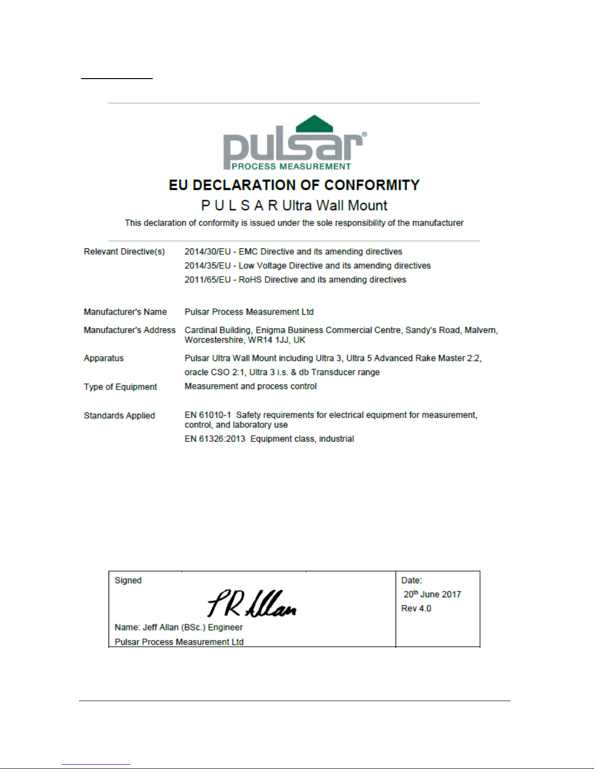
EU Declaration of Conformity
Wall Mount
Page 16
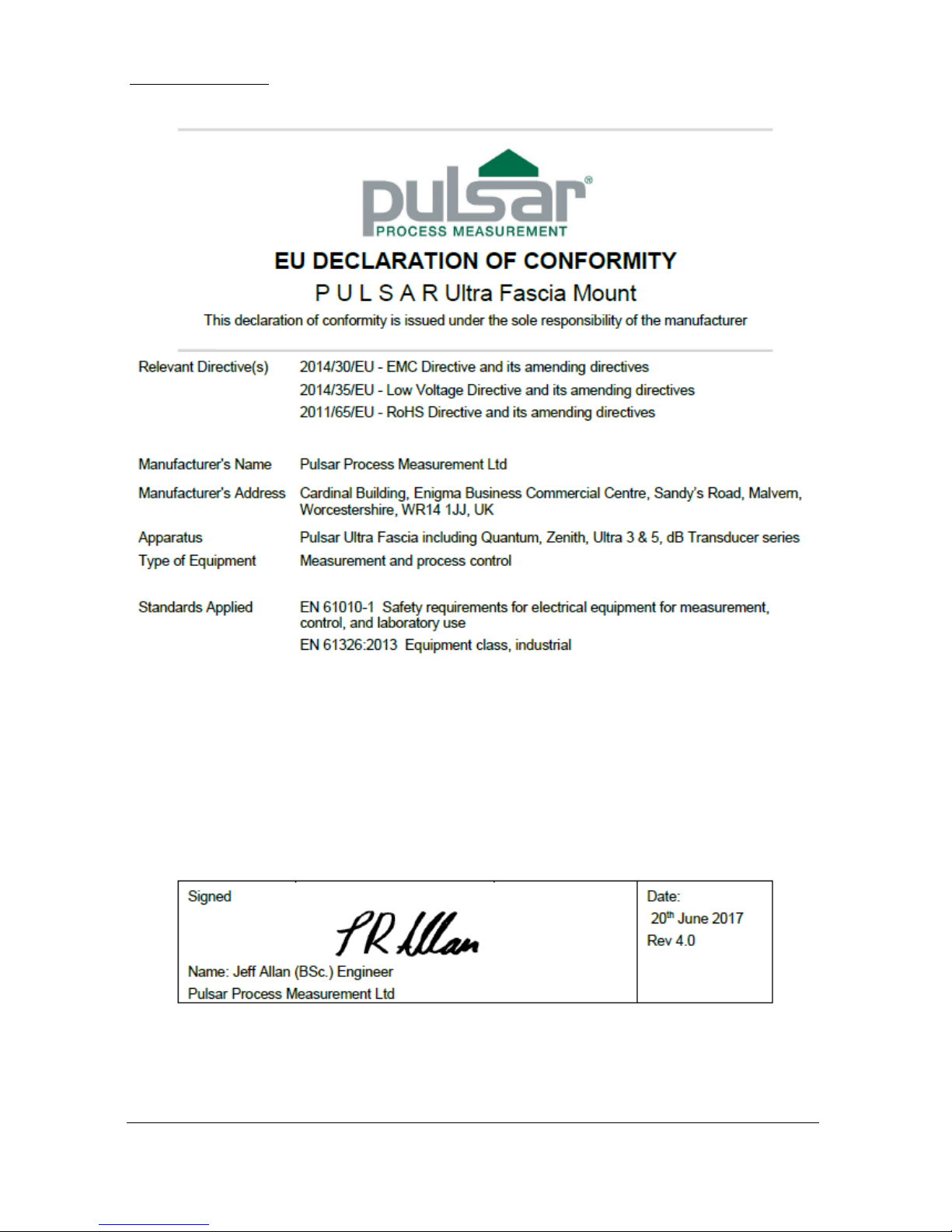
Page 8
Fascia Mount
Page 17

Page 9
Rack and Panel
Page 18

Page 10
This page left blank intentionally
Page 19
Page 11
Chapter 2 Installation
Power Supply Requirements
Ultra 5 can operate from AC supply or from a DC battery. The AC is either
105-120V 50/60Hz or 170-240V 50/60Hz, depending on the position of the
selector switch. The DC is 18-36V. In all cases the Ultra 5 will typically
consume 6W of power, with a maximum of 10W.
Location
All electronic products are susceptible to electrostatic
shock, so follow proper grounding procedures during
installation.
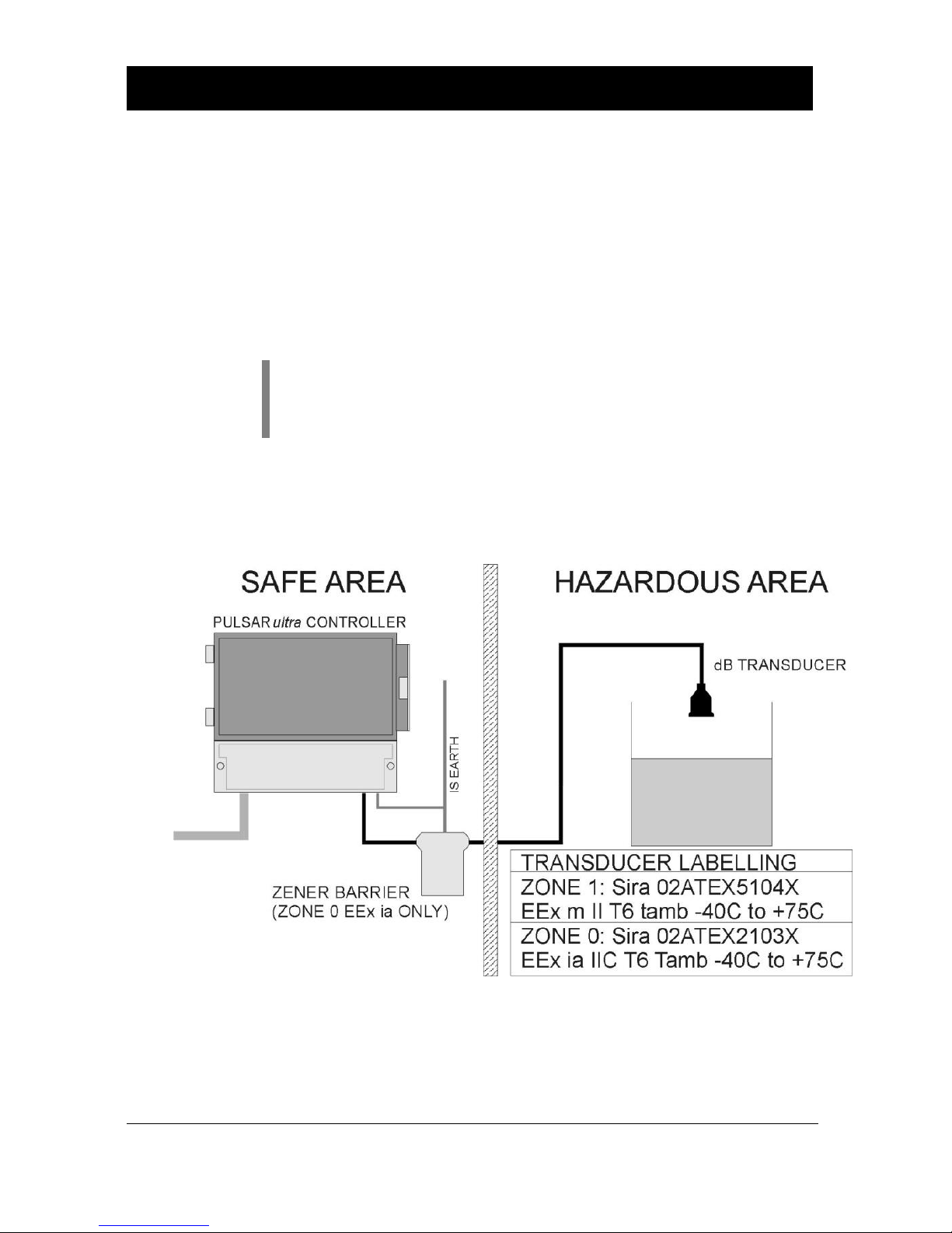
Ultra 5 must be mounted in a non-hazardous (safe) area, and the transducer
fitted in the hazardous area.
Page 20

Page 12
When choosing a location to mount the enclosure, bear in mind the
following:
• Ensure that the Ultra 5 is installed in a “Safe”, non-hazardous, area.
• For a clear view of the LCD display it is recommended that it is
mounted at eye level.
• The mounting surface is vibration-free.
• The ambient temperature is between -20ºC and 50ºC.
• There should be no high voltage cables or inverters close by.
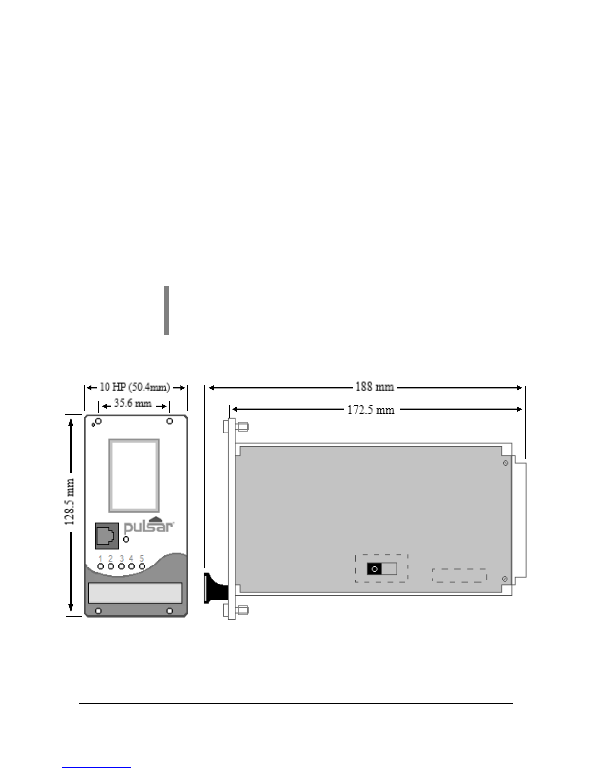
Dimensions
Wall mount
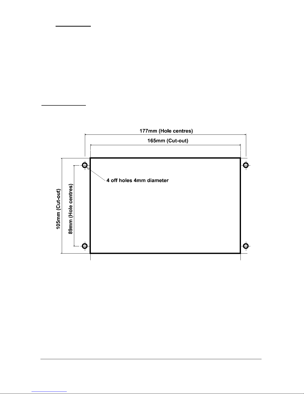
The dimensions of the wall fixing holes are as shown below.
Ultra 5 should be mounted by drilling three holes suitable for size 8 screws
(length to suit your application), and fixing the top screw in place. Hang the
unit on this and fix the two remaining screws by removing the terminals
access cover to access the pre-drilled holes.
Page 21
Page 13
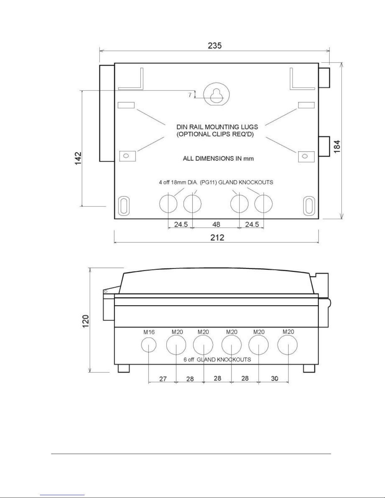
The full dimensions of the enclosure are as shown below.
Page 22
Page 14
Cable Entry
There are 6 cable gland knockouts on the base of the Ultra 5 (5 x M20,
1 x M16) and 4 on the rear (4 x 18mm dia (PG11)). Select which ones you
wish to take out, and remove them by using a circular cutter, such as a tank
cutter. Take care not to damage the circuit board inside whilst undertaking
this. Do not use a hammer, as this may cause damage to the enclosure.
It is recommended that you use suitable cable glands to ensure that the
ingress rating is maintained.
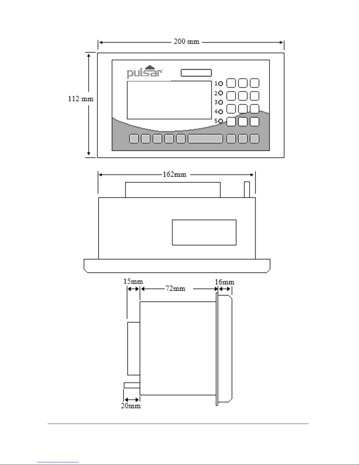
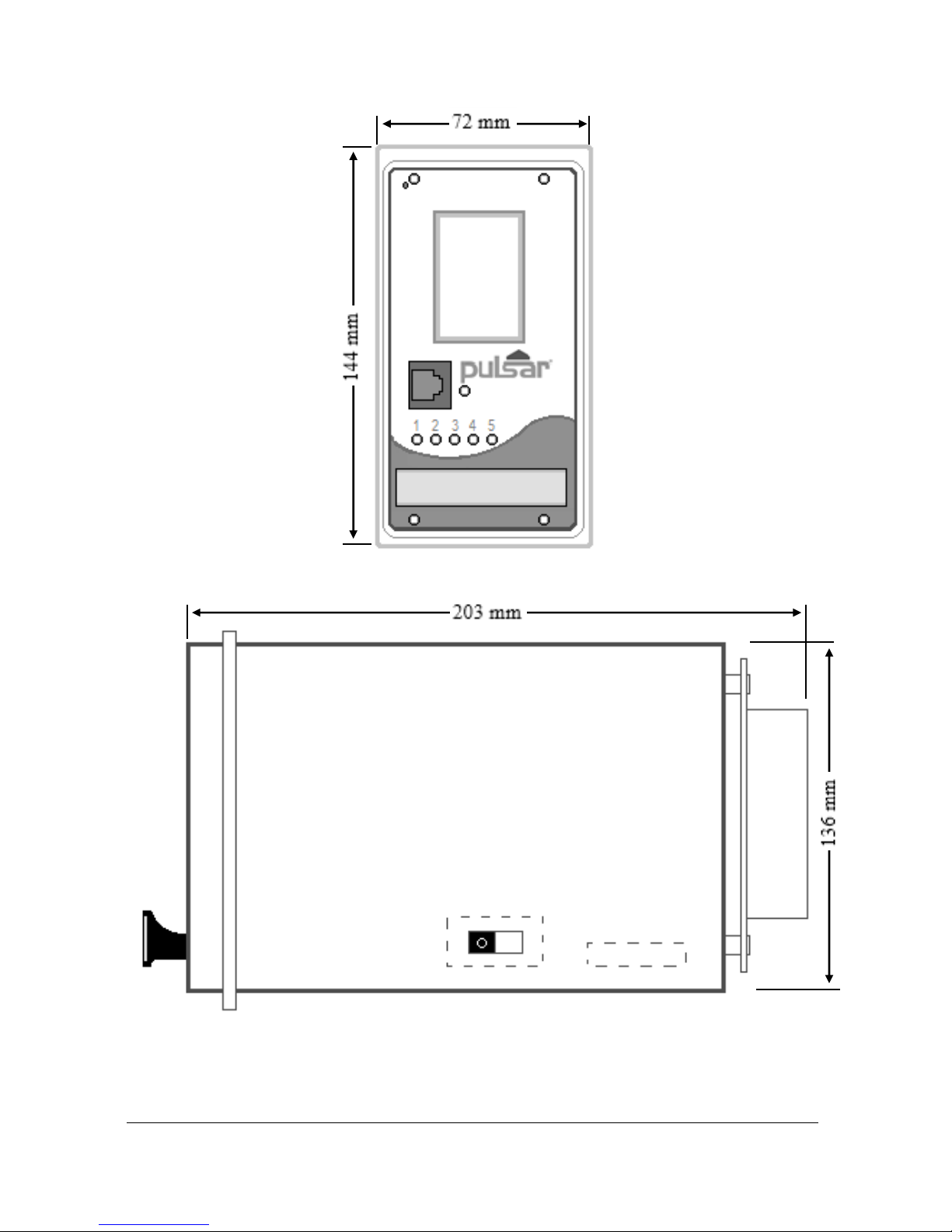
Fascia Mount
The Fascia mount Ultra 5 should be installed by cutting a hole in the panel
as detailed below.
Page 23
Page 15
The full dimensions of the Fascia mount enclosure are as shown below.
Page 24
Page 16
Rack ad Panel
The Ultra 5 rack mount unit is a standard 10HP plug in unit, for a standard
84HP (19”), 160 mm sub rack unit.
The backplane that is supplied with the rack unit should first be fitted to the
back of the sub rack, so that when the rack unit is inserted into the rack it
connects correctly.
To install the unit into the sub rack, slide the Ultra 5 into the rack and secure
by tightening the four captivated screws that are in the faceplate.
The panel mount unit should be installed by cutting a hole of size DIN 68
+0.7
x 138
+1.0
mm in the panel, then insert the Ultra 5 enclosure through the hole,
and tighten the fixing screws from the rear. Make sure you leave sufficient
room for the cables behind the enclosure (a depth of at least 225 mm behind
the panel should suffice).
All electronic products are susceptible to electrostatic
shock, so follow proper grounding procedures during
installation.
Dimensions of the rack enclosure are as shown below:
VOLTAGE SELECTOR
AC POWER FUSE
230
115
Page 25
Page 17
Dimensions of the panel enclosure are as shown below:
VOLTAGE SELECTOR
AC POWER FUSE
230
115
Page 26
Page 18
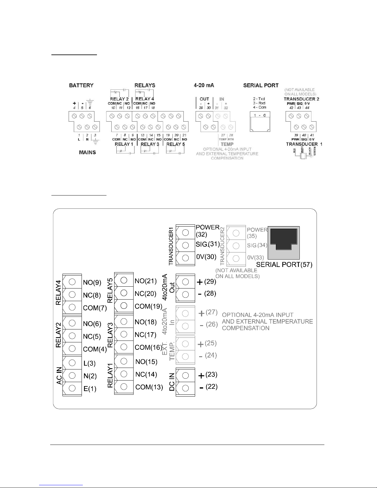
Terminal Connection Details
Wall Mount
The terminal strip is as detailed below. There is also a wiring diagram inside
the terminals access cover.
Fascia Mount
Page 27
Page 19
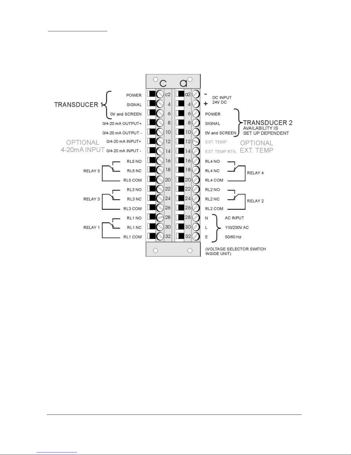
Rack and Panel
The terminal strip is as detailed below. There is also a wiring diagram on the
side of each unit.
Page 28

Page 20
Terminal Connections
Power
Ultra 5 can operate from mains AC and automatically from DC or battery
backup in the event of power failure, or can be operated permanently from
DC or batteries.
Transducer
The transducer should be installed, and connected, in accordance with the
installation instructions contained in the Transducer User Guide.
The entire range of, standard dB transducers are certified for use in
hazardous areas and different models, for each, are available for use in Zone
1 or Zone 0.
Wire the transducer to the Ultra 5’s transducer terminals, terminal numbers
will depend on the unit type, as follows:
Transducer 1
Terminal Connection Details
Unit Type
Red
Power
White
Signal
Black
0 volts
Green
Screen
Wall Mount
39
40
41
41
Fascia Mount
32
31
30
30
Rack or Panel
c2
c4
c6
c6
Transducer 2
Terminal Connection Details
Unit Type
Red
Power
White
Signal
Black
0 volts
Green
Screen
Wall Mount
42
43
44
44
Fascia Mount
35
34
33
33
Rack or Panel
a6
a8
a10
a10
When using 2-core screened extension cable, the Black and Green wires of
the transducer should be connected to the screen of the extension cable.
Page 29

Page 21
For Zone 1 applications a transducer certified to Sira 02ATEX5104X is
used, and must be supplied via a 4000A breaking fuse, which is fitted as
standard to the Ultra 5.
For Zone 0 a transducer certified to Sira 02ATEX2103X is used, which
must be connected to the Ultra 5 controller via an external Zener barrier.
See transducer label for certification details.
Single Transducer mode is used to measure space, level, distance, volume
or flow and the transducer should be connected to Transducer 1 input
terminals.
Dual Transducer mode is used to measure Differential and Average. For
Differential, the upstream transducer should be connected to Transducer
1 input terminal and the downstream transducer to Transducer 2 input
terminal. In cases where the Ultra 5 is required to measure Average, then
transducers can be connected to either one.
Relay Outputs
The five relays can be programmed for a variety of alarms, pump control, or
other process functions. The relay contacts are all rated at 5A at 240V AC.
All connections should be such that the short circuit capacity of the circuits
to which they are connected, is limited by fuses rated so that they do not
exceed the relay rating.
Current Output
This is an isolated (floating) mA output (to 150 V), of 4 - 20mA or 0 20mA, and the load should not exceed 500 .
Current Input (Optional)
This feature is available as an option only. Please consult Pulsar for further
details. The current input is an isolated (floating) mA input (to 150 V), 4 20mA or 0 -20mA.
Temperature Input (Optional)
The external temperature sensor allows more localised compensation of the
measured distance due to changes in temperature.
There are two models, Type A and Type B as follows:
Type A
-25ºC to 50ºC
Type B
-25ºC to 125ºC
Page 30
Page 22
The temperature sensor should be placed close to the point of measurement.
The unit is connected as follows:
Description
Temperature
Sensor
Ultra 5 Wall
mount
Ultra 5
Rack & Panel
Ultra 5 Fascia
Mount
Power Supply
Terminal 1
Terminal 27
Terminal a12
Terminal 25
Return
Terminal 2
Terminal 28
Terminal a14
Terminal 24
Temp Source (P852), should be set to option 4 or 5 depending on the sensor
range, set 4 for type A and 5 for type B (see above), the range is specified on the
label of the sensor.
RS232 Serial Interface
If required, you can connect to the serial interface, to operate your Ultra 5
remotely.
Page 31

Page 23
Voltage Selector and Fuse Location
Wall mount
The voltage selector switch and mains fuse is located, inside the terminal
compartment, to the left of the mains terminals, as illustrated below.
Fascia mount
The voltage selector switch and mains fuse is located under the removable
cover at the bottom of the unit, as illustrated below.
Page 32

Page 24
Rack and Panel mount
The voltage selector switch and mains fuse is situated on the inside of the
bottom PCB, as illustrated below, and can be accessed from the lower side
of the rack unit.
Page 33

Page 25
DON’T FORGET
Make sure you move the voltage
selector switch to the correct
position for your supply.
Important Information
If the equipment is installed or used in a manner not specified in this
manual, then the protection provided by the equipment may be impaired.
Important Information
The rear metal case of the fascia unit must be connected to earth via the
earthing stud located on the rear of the unit, see drawing above, using wiring
to meet local requirements.
Before applying AC power (mains), make sure you have correctly selected
the voltage selector switch, as detailed in the preceding pages.
Please note that all units are supplied set to 230 volts AC for safety reasons,
and a 100mA fuse fitted as standard.
Never operate the Ultra 5 with terminal access exposed.
An external switch or circuit breaker should be installed near to the Ultra 5
to allow the supply to be removed during installation and maintenance. In
addition, the relay contacts should also have a means of isolating them from
the Ultra 5.
Interconnecting cables must be adequately insulated for IEC 664 Category II
installations. Strip back 30 mm of the outer insulation of the cable. Strip
5 mm of insulation from the end of each conductor. Twist all exposed
strands of the conductor together. Insert the stripped conductor into the
terminal block as far as it will go and tighten the terminal block screw.
Ensure that all strands are firmly clamped in the terminal block and that
there is no excess bare conductor showing, and no stray strands.
Page 34

Page 26
Preparation for Operation
Before switching on, check the following:
✓ Ultra 5 is mounted correctly and is in a ‘safe’ area.
✓ The power supply is correctly installed.
✓ The voltage selector switch is in the correct position.
✓ The relays are connected correctly.
Maintenance
There are no user serviceable parts inside Ultra 5, except the mains fuse. If
you experience any problems with the unit, then please contact Pulsar
Process Measurement for advice.
To clean the equipment, wipe with a damp cloth. Do not use any solvents on
the enclosure.
Important Information
The unique DATEM software comes into operation as soon as power is
applied, and is designed to monitor a moving level or target with the
transducer in a fixed position.
If, after any period of use, it should become necessary to move the
transducer, for any reason, from its original operating position, switch off
the Ultra 5, before proceeding, to prevent any undesirable updates to the
DATEM trace. If after moving the transducer the reading is not as expected,
please refer to Chapter 9 Troubleshooting.
Page 35

Page 27
This page left blank intentionally
Page 36

Page 28
Chapter 3 How To Use Your
Ultra 5
Operating the Controls
Display
The display provides information on the current mode of operation, and
status of the remote communication. Whilst in the Run Mode it will display
the current level reading and its units of measure, along with status
messages with regards to the Transducer, Echo reception and Fail Safe
Mode. Additionally, it can be programmed to provide status messages on
alarms, pumps etc. When in the Program mode the display is used to read
information on the Menu System, Parameter Number and parameter details
and values, which can be entered. During Test Mode, the display is used to
monitor the simulated level. A bar graph is also provided which will provide
a visual reading of the level, in percentage of span.
Run Mode Program Mode Test Mode 100%
000.000
XXXXXXXXXXXX
REMOTE COMMUNICATOR OFF 0%
1) Mode status enunciator displays the current mode of operation.
2) Main 6-digit display:
Run Mode, current measurement displayed, dependent on mode and
measurement unit's chosen, and value of Hot Key function selected.
Program Mode, displays parameter number and values entered for
parameters.
Test Mode, displays simulated level.
1 2 3
4
5
6
Page 37

Page 29
3) Auxiliary Display, scrolling twelve-digit display.
Run Mode, displays measurement units (P104), status messages on
signal and transducer, detail of Hot Key function selected. It can be also
programmed to provide notification messages on alarms and pumps etc.
for full details please refer to Display Parameters in the relevant
parameter listing.
Program Mode, displays Menu and Sub Menu headings, parameter
details and options.
4) Communicator status enunciator displays the current status of, Remote
Communicator (rack and panel versions only) or remote PC connection.
5) Bargraph, display, gives visual indication of measurement in % of span.
6) Level indicators
Run Mode, indicates in which direction the level is moving.
Program Mode, indicates at which level of the menu system you are at.
The display on the wall, fascia, rack and panel mount unit contain the same
information, the difference being the aspect ratio of each display.
There are two main operating modes for your Ultra 5, Run Mode and
Program Mode. There is also a Test Mode, used for checking the set-up.
All modes are now described.
Run Mode
This mode is used once the Ultra 5 has been set up in program mode. It is
also the default mode that the unit reverts to when it resumes operation after
a power failure.
When Ultra 5 is switched on for the first time, it will display, in metres, the
distance from the transducer face to the target. All relays by default are
switched off.
After programming is complete, any relays that are set will operate when the
level reaches the relevant setpoint, and the LED’s will change colour (unless
specifically switched off).
Page 38

Page 30
Program Mode
This mode is used to set up the Ultra 5 or change information already set.
You must use either the built-in keypad (standard) or, in the case of the rack
and panel mount, the remote communicator (both keypads are identical in
the way they operate). Alternatively, the unit can be set up with a PC via the
RS 232 Serial Interface.
Entering a value for each of the parameters that are relevant to your
application provides all the programming information.
How to Access Program Mode
Wall and Fascia mount
In the case of the wall and fascia mounted Ultra 5, to enter program mode,
you simply enter the passcode, via the keypad, followed by the ENTER key.
The default passcode is 1997, so you would press the following:
Rack and Panel
The Remote Communicator is used to program the rack and panel version of
the Ultra 5. Before you can commence programming, it is first necessary to
activate the communication between the Ultra 5 and the Communicator.
This is achieved by offering the Remote Communicator up to the Ultra 5 so
that the arrow point in the Pulsar Logo on the Communicator is in line with
the corresponding arrow point on the front panel of the unit and lightly
‘touching’ the unit with the communicator (see following figure).
Confirmation that communication has been successfully achieved will be
indicated by a change of the Communicator status display, at the bottom of
the LCD from “Communicator Off” to “Remote Communicator On”. Once
communications have been activated the Remote Communicator can be used
up to I metre away from the unit but should be ‘aimed’ at the unit whilst
entering information.
On returning the unit to Run Mode ensure that communications between the
Remote Communicator and the Ultra 5 are switched off by once again
‘touching’ the unit with the Communicator and confirm the display status
changes back to “Communicator Off”
Page 39

Page 31
Once communications have been activated, you simply enter the passcode,
via the keypad, followed by the ENTER key. The default passcode is 1997,
so you would press the following:
Note
There is a time-out period of 15 minutes when in program mode, after
which time run mode will be resumed if you do not press any keys.
Align the arrows to
activate the infra-red
Page 40

Page 32
Hot Keys
There are five hot keys on the keypad, which can be used to quickly access
common parameters for viewing only, while in Run Mode. Pressing the hot
key once will display the first parameter, then repeated pressing will display
the others, then the Ultra 5 reverts to Run Mode. In program mode, they
have different functions, the functions are shown below.
Hot
Key
Run Mode
Program Mode
When application is Flow, view
non-resettable totaliser. View
and reset the resettable totaliser.
When application is Pump, view
total pump running hours, and
individual pump running hours.
Not used with Ultra 5.
Displays echo confidence, echo
strength, H.A.L.L., average
noise, peak noise or
temperature.
Not used with Ultra 5.
When application is Pump, view
total number of pump starts and
individual pump starts.
Reset parameter to default
setting.
Instantaneous mA output.
Not used with Ultra 5.
Dependant on application
displays Distance, Level, Space,
Head, Flow, Volume or rate of
change of level.
Toggle relay setpoints
between Ultra 5’s units of
measure and % of span.
Not used with Ultra 5.
Takes you to the last
parameter edited, when you
first enter program mode.
Gives details of unit type,
software revision and serial
number.
Enter decimal point
Page 41

Page 33
Menu Keys
The menu keys have the following functions:
Menu Key
Function
1) Arrow keys for moving left and right around the menu
system.
2) Used in test mode to simulate the level moving up and
down.
1) Used to confirm each action (for example select a
menu option) or when entering a parameter number or
value.
2) Used to confirm questions asked by your Ultra 5 such
as before restoring factory defaults.
Used to navigate up a level in the menu system, and back
to run mode.
Used to cancel a value entered in error.
Numeric Keys
These keys are used for entering numerical information during
programming.
Page 42

Page 34
There are two means of editing parameters, directly or using the menu
system. Each is now described.
Using the Menu System
The menu system has been designed to make the changing of parameters
very simple. There are two levels of menu: Main Menu and Sub Menu.
On the display, there is a line of text that displays the menu system. Pressing
the arrow keys scrolls the display between the top-level menu items, (as the
example shown below, starting at Ultra Wizard).
As you press the cursor keys to scroll left and right between these, you can
press ENTER at any time, to select the desired menu heading, and take you
to the sub-menu.
Each of these options, along with their sub-menus, are described later in this
manual. When you move down into the sub-menu, you can scroll round
using the arrow keys, press ENTER to go to the required section of
parameters.
Once you have reached the relevant section, scroll through the parameters,
and enter the necessary information. To enter the information, use the
numeric keys and then press ENTER, you will then see the message
“Saved!” If you press CANCEL, then the change you made will not be
saved, and the message “Unchanged!!” will be displayed.
When you have finished, press CANCEL to go back to the previous level.
When you have reached the top level, then the Ultra 5 will ask for
confirmation before allowing you to go back into run mode. This is done by
pressing ENTER at the display prompt.
Ultra Wizard
Quick Setup
Application
Relays
Data Logs
Compensation
mA Output
Display
Stability
System
Test
Device
Comm
Echo
Processing
Volume
Page 43

Page 35
Note
You can tell which part of the menu system you are in, as the up/down level
indicators, (arrows) next to the bar graph will indicate as follows:
• Top level menu: Down arrow on, to indicate you can move down.
• Sub-menu: Up and Down arrows on, to indicate you can move up to
the top level, and down to parameter level.
• Parameter Level: Up arrow on, to indicate you can move up to sub-
menu level.
• Parameter Editing: No arrows on.
Directly Editing Parameters
If you already know the number of the parameter, that you wish to look at or
edit, simply type the number in at any time while you are in the menu
system. Thus, if you are in either the menu or sub-menu level by pressing a
numeric key, you can enter the parameter number directly and jump straight
there. You cannot type a parameter number whilst at parameter level, only at
one of the two menu levels.
When you are at a parameter, the text line rotates automatically displaying
the parameter name, number, the applicable units and the maximum and
minimum figure you can enter. The top line shows the value you are setting.
Once you have accessed a parameter, you can either just look at it, or change
it.
Once a parameter has been changed, press ENTER and you will see the
message “Saved!”. If you press CANCEL, then the change you made will
not be saved, and the message “Unchanged!!” will be displayed.
TIP
You can jump straight to the last parameter
you edited, by pressing ‘+/-’ when you first
enter program mode.
Page 44

Page 36
Test Mode
Test mode is used to simulate the application and confirm that all parameters
and relay setpoints have been entered as expected. During simulation, there
is a choice of whether the relays will change state (hard simulation) or not
(soft simulation), but the LED’s will always change colour as programmed,
and the mA output will change in accordance to the chosen mode of
operation. If you wish to test the logic of the system that the relays are
connected to then select hard simulation, but if you don’t wish to change
the relay state, then select a soft simulation.
There are two simulation modes, automatic and manual. Automatic
simulation will move the level up and down between empty level or the predetermined Start Level (P983) and Pump/Control relay switch points, if
you wish to change the direction of the level movement e.g. to go beyond
relay setpoints, this can be done by using the arrow keys. In manual
simulation, using the arrow keys will allow you to move the level up and
down as required.
To enter simulation, first go to program mode. Using the menu system,
select menu item ‘Test’, then sub-menu item ‘Simulation’. Simply change
the value of the parameter P980 to one of the following:
1= Manual soft simulation
2= Automatic soft simulation
3= Manual hard simulation
4= Automatic hard simulation
To return to program mode, press CANCEL and test mode will end.
When in manual simulation, by default test mode will move the level by
0.1m steps. Altering the increment (P981) will change this value.
In automatic mode, the rate at which the level moves up and down is set by
the increment (P981) in metres, the rate (P982) in minutes, which can be
changed to make the level move up and down faster. E.g. if increment
(P981) is set for 0.1m and rate (P982) is set to 1 min then the level will
increase or decrease at a rate of 0.1m/min. To make the simulated level
move slower, decrease the value in increment (P981) or increase the value
in rate (P982). To make the simulated level move faster, increase the value
in increment (P981) or decrease the value in rate (P982).
Page 45

Page 37
Using the RS232 Serial Interface
The RS232 serial interface is used to communicate between the Ultra 5 and
a PC using the optional Ultra PC and other associated Pulsar software
packages, to obtain information such as data logging and view echo traces
upload, download and save parameter files. In addition, it can also be used
to control or obtain information using a standard PC or other computer base
equipment. To do so, the settings for control are as follows: baud rate
19,200, 8 data bits, no parity, 1 stop bits.
The device should be connected as shown in Chapter 2 Installation.
To use the device remotely, you need to log on to start, and log off when
finished. When logged on, Ultra 5 will show ‘Remote ON’ on the display,
and “Communicator OFF” when logged off.
All commands should be followed by a carriage return.
The unit will respond either OK (or a value) if the command is accepted, or
NO if it is not.
To log on, send the command
/ACCESS:pppp where pppp is the passcode (P922).
To log off, send the command
/ACCESS:OFF
To read a parameter value, send the command
/Pxxx where xxx is the parameter you wish to read, and the Ultra 5 will
respond with the parameter value.
To set a parameter, send the command
/Pxxx:yy where xxx is the parameter number, and yy is the value you wish
to set it to.
Page 46

Page 38
Other commands you can use are:
/LEVEL (shows current level)
/SPACE (shows current space)
/HEAD (shows current OCM head)
/FLOW (shows current OCM flow)
/TEMPERATURE (shows current temperature)
/CURRENTOUT (show the mA output value)
/CURRENTIN (show the mA input value)
/BACKUP1 (take backup of parameters to area 1)
/BACKUP2 (take backup of parameters to area 2)
/RESTORE1 (restore parameters from area 1)
/RESTORE2 (restore parameters from area 2)
Please consult Pulsar Process Measurement or contact your local Pulsar
representative for further details and a full list of available commands.
Page 47

Page 39
Parameter Defaults
Factory Defaults
Factory Defaults
When first installing the Ultra 5, or subsequently moving or using the unit
on a new application, before proceeding to program the unit for its intended
application it is recommended that you ensure that all parameters are at their
default values by completing a Factory Defaults P930, as described in the
relevant unit type parameter guide.
When you first switch Ultra 5 on, it will be reading the distance from the
face of the transducer to the surface. It will be indicating in metres, as
shown on the display. All relays are set OFF.
The date (P931) and time (P932) in Ultra 5 were set at the factory, but may
need checking, and amending if, for example the application is in a time
zone other than GMT, see relevant unit Parameter listing for full details.
TIP
In some applications, it is simplest to empty
the vessel, take a reading from the Ultra 5 for
distance and then setup the empty level to this
figure.
Once you are satisfied with the installation, and Ultra 5 is reading what you
would expect in terms of distance from the face of the transducer to the
material level, then you can proceed with programming, for the intended
application. It is sensible to program all the required parameters at the same
time. The system will be then set-up.
Note that the span is automatically calculated from the empty level, so the
empty level should be entered first.
Page 48

Page 40
Chapter 4 Ultra Wizard
The Ultra Wizard menu allows you to turn Ultra 5 into anyone of three
dedicated ultrasonic devices to exactly suit the requirements of your
application.
Ultra Wizard Menu
To access the Ultra Wizard, you need to go from Run Mode to Program
Mode.
Enter Program Mode
First you need to go from run mode into program mode. Assuming the
passcode is the default 1997, then you should enter this.
Choose Ultra Wizard
Now you need to go into the Ultra Wizard. You will see on the menu the
words ‘Ultra Wizard’, which is the first item on the menu, select and press
This takes you to the “Select Application Menu”
and provides the choice of:
1 = Level or Volume measurement (Lev/Vol
2 = Pump Control or Differential measurement and control (Pump/Diff)
3 = Open channel Flow measurement (Flow)
Once you have selected the application of your choice the Ultra 5 will be
configured to the unit type specific to that task as follows:
Application
Unit Type
1 = Lev/Vol
When selected Ultra 5 will be configured
as a Level Star 5
2 = Pump/Diff
When selected Ultra 5 will be configured
as an Advanced 5
3 = Flow
When selected Ultra 5 will be configured
as a Flow 5
Page 49

Page 41
Lev/Vol
If you require to set up a level or volume application, with or without a
choice of control functions then press “1” followed by “ENTER” the
message “Loading ***” will be displayed and your Ultra 5 will be
configured as a Level Star 5. Confirmation that configuration has been
completed will be given by the unit type, software version and serial number
being displayed briefly on the LCD and the unit advancing to the relevant
“Quick Setup” menu.
For full details on how to programme the Level Star 5, using the Quick
Setup Menu, please proceed to Chapter 5 Level/Volume. For a full
description of all features and parameters please refer to Chapter 8
Parameter Listing and Description.
Level Star 5
The Level Star provides the ability to convert level measurement to enable
the contents of a vessel to be displayed in volume, along with control
functions, for a complete range of vessel shapes. Also, available within the
unit is a customised 32-point calibration routine which permits the
calculation of volume in non - standard vessels.
The Level Star 5 can measure from 0.12 m to 40 m from the face of the
transducer to the surface being monitored, dependent on the transducer used.
The Level Star 5 can show details of level, space, distance, units of volume
or the average of two points of measurement on the display.
The five user-definable relays with individual setpoints can be programmed
to activate devices such as pumps or other control equipment.
The 4-20 mA output is fully programmable to provide an output relative to
level, space, distance or volume of either point, when two points are being
measured or the average of two points of measurement. The optional mA
Input can be used to connect devices such as pressure transducers so that the
features of the Level Star 5 can be used in applications where ultrasonic
transducers are unable to operate.
Page 50

Page 42
Pump/Diff
If you require to set up a pump or differential application, then press “2”
followed by “ENTER” the message “Loading ***” will be displayed and
your Ultra 5 will be configured as an Advanced 5. Confirmation that
configuration has been completed will be given by the unit type, software
version and serial number being displayed briefly on the LCD and the unit
advancing to the relevant “Quick Setup” menu.
For full details on how to programme the Advanced 5, using the Quick
Setup Menu, please proceed to Chapter 6 Pump/Differential. For a full
description of all features and parameters please refer to Chapter 8
Parameter Listing and Description.
Advanced 5
The Advanced 5 level controller provides sophisticated pump control with a
complete range of pump “duties” being available and advanced control
routines for use with differential and level control, for an extremely wide
variety of applications.
The Advanced 5 can measure from 0.12m to 40m from the face of the
transducer to the surface being monitored, dependent on the transducer used.
The Advanced 5 can show level, space, distance or the average or
differential between two points of measurement, on the display.
The five user definable relays with individual setpoints can be programmed
to activate alarms, pump starters, or other control equipment.
The 4-20 mA output is fully programmable to provide an output relative to
level, distance, average or differential. The optional mA Input can be used
to connect devices such as pressure transducers so that the sophisticated
control routines of the Advanced 5 can be used in applications where
ultrasonic transducer are unable to operate.
Flow
If you require to set up a flow application, then press “3” followed by
“ENTER” the message “Loading ***” will be displayed and your Ultra 5
will be configured as a Flow 5. Confirmation that configuration has been
completed will be given by the unit type, software version and serial number
being displayed briefly on the LCD and the unit advancing to the relevant
“Quick Setup” menu.
For full details on how to programme the Flow 5, using the Quick Setup
Menu, please proceed to Chapter 7 Flow. For a full description of all
features and parameters please refer to Chapter 8 Parameter Listing and
Description.
Page 51

Page 43
Flow 5
The Flow 5 open channel flowmeter provides comprehensive flow
monitoring with data logging and control functions for a complete range of
flumes, weirs and channels. Flow calculations to the British Standard
BS3680 are available within the software together with calculations for a
wide variety of other primary elements. For applications where there is no
primary element, the optional 4-20mA input can be used to connect a
Doppler Velocity Sensor (available from Pulsar) to enable the calculation of
Flow Q = Velocity x area, for a wide range of channel shapes. Also,
available within the unit is a customised 32-point calibration routine which
also permits the flow measurement of non - standard flumes and weirs.
The Flow 5 can measure from 0.0 m to 15 m from the transducer to the
surface being monitored, dependent on the transducer used. The Flow 5 can
show details of level, space, distance, head or flow on the display along
with a totaliser if desired.
The five user-definable relays with individual setpoints can be programmed
to activate devices such as pumps, samplers, remote totalisers or other
control equipment. The 4-20 mA output is fully programmable to provide
an output relative to level, space, distance, head or flow.
Page 52

Page 44
Chapter 5 Level / Volume
When Ultra Wizard = 1 Level/Volume
Ultra 5 is configured as a Level Star 5
This quick set-up guide shows you how to get up and running within a few
minutes of installing your Level Star.
Enter Program Mode
First you need to go from run mode into program mode. Assuming the
passcode is the default 1997, then you should enter this.
Choose Quick Setup
Now you need to go into the quick setup. You will see on the display the
words ‘Ultra Wizard’, press the ‘right hand’ arrow key and this will take you
to the ‘Quick Setup’ menu option. Try pressing either of the two arrow keys
to see some more menu options, but return to Quick Setup, and press
This takes you to the “Quick Setup Menu”.
This takes you to the common applications menu,
and a number of options will appear on the
display.
Note
If you have already setup a common application, then there will be a number
shown other than 0, and you will see messages showing what the current
setup is. If you want to reset this and start again, press 0 (which will reset all
the quick setup parameters), otherwise pressing ENTER will allow you to
edit the parameters that have been set.
Page 53

Page 45
Choose Your Application
There are two categories of application, which are all described later in this
chapter. They are level or volume all with the choice of control functions
and alarms.
If you want to set-up a basic level monitoring application, as described in
the following example 1, then choose 1.
If you want to set-up a level monitoring application with control relays, as
described in the following example 2, then choose 1 and choose either
control down (press 1) or control up (press 2).
If you want to set-up a volume application, as described in the following
example 3, then choose 2.
Once you have chosen your application you will be asked a series of
questions which are answered by choosing the appropriate option as detailed
in the flow chart below. Once all of the questions have been answered you
will be prompted to provide further information, as detailed in the tables
below, in order to complete the programming of the unit.
Page 54

Page 46
The Quick Setup Menu detailing the questions you will be asked when setting up
your Level Star, via the Quick Setup is shown below.
Quick Setup Menu
Quick Setup
For Each Alarm
1 = Set to Relay 1
2 = Set to Relay 2
3 = Set to Relay 3
4 = Set to Relay 4
5 = Set to Relay 5
0 = No Control
1 = Control Down
2 = Control Up
No. of Control Relays
1 = 1 Control Relay
2 = 2 Control Relay
3 = 3 Control Relay
4 = 4 Control Relay
5 = 5 Control Relay
For each Cntl. Relay
1 = Set to Relay1
2 = Set to Relay 2
3 = Set to Relay 3
4 = Set to Relay 4
5 = Set to Relay 5
How Many Alarm
0 = No Alarms
1 = One Alarm
2 = Two Alarms
3 = Three Alarms
4 = Four Alarms
5 = Five Alarms
List will be truncated
according to the number
of Control relays
selected
For Each Alarm
1 = High Alarm
2 = Low Alarm
3 = Hi Hi Alarm
4 = Lo Lo Alarm
5 = Loss of Echo
Application
1 = Level
2 = Volume
Page 55

Page 47
Wait ….
Parameter
Default
Description
P101 Transducer
2 = dB6
Type of transducer being used.
P102 Material
1 = liquid
Material in the vessel, either liquid
or solid. If the solid lays flat, then it
can be entered as liquid.
P104
Measurement
Units
1 = metres
Select units to be used for
programming measurement
information.
P105
Empty Level
6 m
Distance from the face of the
transducer to the material at the
bottom of the vessel.
P106
Span
5.7 m
Distance from the empty level (0%
full) to span (100% full).
If you have selected a Volume Application, you will now be prompted to
enter details required for the calculation of volume
Parameter
Default
Description
P600
Vessel Shape
0=Cyl. Flat
Base
Shape of vessel being monitored.
P601-P603
Vessel
Dimensions
dependant on
vessel shape
selected.
Enter Vessel dimensions as required
P605
Volume units
3 = Cubic m
Selects volume units required.
P607
Max Volume
Read Only
Displays the calculated Volume in
P605 units.
For More Options Hit Enter
Page 56

Page 48
Parameter
Default
Description
P213 / P214
Relay 1
ON/OFF
setpoints
Factory preset as a %
to appropriate level
according to the span
already entered.
See tables below
Either Alarm or Level control.
Depends on application.
P223 / P224
Relay 2
ON/OFF
setpoints
Factory preset as a %
to appropriate level
according to the span
already entered.
See tables below
Either Alarm or Level control.
Depends on application.
P233 / P234
Relay 3
ON/OFF
setpoints
Factory preset as a %
to appropriate level
according to the span
already entered.
See tables below
Either Alarm or Level control.
Depends on application.
P243 / P244
Relay 4
ON/OFF
setpoints
Factory preset as a %
to appropriate level
according to the span
already entered.
See tables below
Either Alarm or Level control.
Depends on application.
P253 / P254
Relay 5
ON/OFF
setpoints
Factory preset as a %
to appropriate level
according to the span
already entered.
See tables below
Either Alarm or Level control.
Depends on application.
P830
mA Out Range
2= 4 to 20 mA
Determines the mA output
range.
0 = Off, 1 = 0 to 20mA,
2 = 4 to 20mA, 3 = 20 to
0mA, 4 = 20 to 4mA.
P870
Fill Damping
10 m/min
Rate of maximum fill rate (set
above the actual fill rate of the
vessel).
P871
Empty Damping
10 m/min
Rate of maximum empty rate
(set above the actual empty
rate of the vessel).
Page 57

Page 49
The default values used for determining the relay setpoints, when setting
Alarm and Control relays, via the Quick Setup menu are entered as a % of
span and are as follows.
Application
Number of
Cntl Relays
Cntl Relay
Number
On
Setpoint
Off
Setpoint
Cntl. Down
One
Control 1
80%
20%
Cntl. Down
Two
Control 1
Control 2
80%
70%
20%
20%
Cntl. Down
Three
Control 1
Control 2
Control 3
80%
70%
60%
20%
20%
20%
Cntl. Down
Four
Control 1
Control 2
Control 3
Control 4
80%
70%
60%
50%
20%
20%
20%
20%
Cntl. Down
Five
Control 1
Control 2
Control 3
Control 4
Control 5
80%
70%
60%
50%
40%
20%
20%
20%
20%
20%
Application
Number of
Cntl Relays
Cntl Relay
Number
On
Setpoint
Off
Setpoint
Cntl. Up
One
Control 1
20%
80%
Cntl. Up
Two
Control 1
Control 2
20%
30%
80%
80%
Cntl. Up
Three
Control 1
Control 2
Control 3
20%
30%
40%
80%
80%
80%
Cntl. Up
Four
Control 1
Control 2
Control 3
Control 4
20%
30%
40%
50%
80%
80%
80%
80%
Cntl. Up
Five
Control 1
Control 2
Control 3
Control 4
Control 5
20%
30%
40%
50%
60%
80%
80%
80%
80%
80%
Page 58

Page 50
Relay
Function
Relay I.D.
On
Setpoint
Off
Setpoint
Alarm
HiHi
90%
85%
Alarm
High
85%
80%
Alarm
Low
10%
15%
Alarm
LoLo
5%
10%
Page 59

Page 51
Example 1 Level Monitoring with Alarms
A vessel, containing a liquid that has a variation in level that is to be
monitored, with a high-level alarm set on Relay 1, and low level alarm set
on Relay 2.
empty distance (P105), 3.5m
100%, span (P106), 2.8m
85% , high alarm on (P213), 2.38m
80% , high alarm off (P214), 2.24m
15% , low alarm off (P224), 0.42m
10% , low alarm on (P223), 0.28m
0% , empty level
In this example, when the level rises to 2.38 m, relay 1 will come on until
the level drops to 2.24 m when it will turn off. If the level drops to 0.28 m,
then relay 2 will come on until it rises 0.42 m when it will turn off.
The display will show the level in the tank.
The mA output will be representative of level where 4mA = empty level
(0%) and 20mA = 2.8m (100%).
Page 60

Page 52
To program the unit for Example 1 Level Monitoring with alarms by
using the Quick Setup menu proceed as follows.
If required access the Program Mode
Key in the passcode 1997 and press ENTER
Using the ‘right’ arrow key go to the Quick Setup menu press ENTER and
as prompted, by the questions, select the relevant option and ENTER.
Question
Option
Level/Volume
1 = Level App.
Control
0 = No Control
No. of Alarms
2 = 2 Alarms
Type Alarm 1
1 = High
Alarm No 1
1 = Set Relay 1
Type Alarm 2
2 = Low
Alarm No 2
2 = Set Relay 2
Xducer (P101)
2 = dB6
Material (P102)
1 = Liquid
Measnt Units (P104)
1 = metres
Empty Level (P105)
3.5 (metres)
Span (P106)
2.8 (metres)
Programming is now complete and the unit can be returned to the run mode,
press CANCEL until Run Mode? Is displayed on the LCD press ENTER,
and the Level Star 5 will return to the Run Mode.
Note
If relay setpoints do not meet the exact requirements of the application, they
can be modified to suit by pressing ENTER when, “For More Options Hit
Enter”, is displayed and entering new values to relay setpoints as required.
Alternatively, the relevant relay setpoint can be accessed either by the main
menu system or directly via parameter number and changed as necessary.
Page 61

Page 53
Example 2 Level Monitoring and Control (up or down)
A vessel, containing a liquid that has a variation in level that is to be
monitored, and when the level reaches a specific point, the vessel is pumped
down, with the fluid being transferred to another process. The pump will be
assigned to Relay 1 a High Alarm to Relay 2 and Low Alarm to Relay 5.
empty distance (P105), 3.5m
100%, span (P106), 2.8m
85%, high alarm on (P223), 2.38m
80%, high alarm off (P224), 2.24m
80%, control (down) on (P213), 2.24m
15% , low alarm off (P254), 0.42m
10%, low alarm on (P253), 0.28m
0%, empty level
20%, control (down) off (P214), 0.7m
In this example, there is a pump (relay 1), which will come on if the level
rises to 2.24 m, and go off when the level drops to 0.7 m. (control down). If
the level rises to 2.4 m, then the high-level alarm (relay 2) will come on
until the level drops to 2.24 m. If the level falls to 0.28m, then the low-level
alarm (relay 5) will come on until the level rises to 0.42 m.
Alternatively, if it is a control up application, then the on and off points for
the control relay are reversed, so the control relay comes on when the level
is at 0.7 m and goes off when it rises to 2.24 m.
The display will show the level in the tank and the mA output will be
representative of level where 4mA = empty level (0%) and 20mA = 2.8m
(100%).
Page 62

Page 54
To program the unit for Example 2 Level Monitoring and Control by
using the Quick Setup menu proceed as follows.
If required access the Program Mode
Key in the passcode 1997 and press ENTER
Using the ‘right’ arrow key go to the Quick Setup menu press ENTER and
as prompted, by the questions, select the relevant option and ENTER.
Question
Option
Level/Volume
1= Level App.
Control
1= Control Down
No. of Controls
1 = 1 Relay
Control No. 1
1 = Set Relay 1
No. of Alarms
2 = 2 Alarms
Type Alarm 1
1 = High
Alarm No. 1
2 = Set Relay 2
Type Alarm 2
2 = Low
Alarm No. 2
5 = Set Relay 5
Xducer (P101)
2 = dB6
Material (P102)
1= Liquid
Measnt Units (P104)
1 = metres
Empty Level (P105)
3.5 (metres)
Span (P106)
2.8 (metres)
Programming is now complete and the unit can be returned to the run mode,
press CANCEL until Run Mode? Is displayed on the LCD press ENTER,
and the Level Star 5 will return to the Run Mode.
Note
If relay setpoints do not meet the exact requirements of the application, they
can be modified to suit by pressing ENTER when, “For More Options Hit
Enter”, is displayed and entering new values to relay setpoints as required.
Alternatively, the relevant relay setpoint can be accessed either by the main
menu system or directly via parameter number and changed as necessary.
Page 63

Page 55
Example 3 Volume Application
A cylindrical tank with a diameter of 2m and a flat base that is typically
used to temporarily hold liquid, and you wish to know the volume of liquid.
You also require a high and low alarm and when the level reaches a specific
point, the vessel is pumped down, with the fluid being transferred to another
process.
empty distance (P105), 3.5m
100%, span (P106), 2.8m
85%, high alarm on (P243), 2.38m
80%, high alarm off (P244), 2.24m
80%, control (down) on (P213), 2.24m
15% , low alarm off (P254), 0.42m
10%, low alarm on (P253), 0.28m
0%, empty level
20%, control (down) off (P214), 0.7m
In this example, there is a pump (relay 1), which will come on if the level
rises to 2.24 m, and go off when the level drops to 0.7 m. (control down). If
the level rises to 2.4 m, then the high-level alarm (relay 4) will come on
until the level drops to 2.24 m. If the level falls to 0.28m, then the low-level
alarm (relay 5) will come on until the level rises to 0.42 m.
The display will show the volume of fluid in the tank and the mA output
will be representative of Volume where 4mA = empty (0%) and 20mA =
Max Volume (100%).
Page 64

Page 56
To program the Level Star for Example 3 Volume Application with
Control by using the Quick Setup menu proceed as follows.
If required access the Program Mode
Key in the passcode 1997 and press ENTER
Using the ‘right’ arrow key go to the Quick Setup menu press ENTER and
as prompted, by the questions, select the relevant option and ENTER.
Question
Option
Level/Volume
2= Volume App.
Control
1= Control Down
No. of Controls
1 = 1 Relay
Control No. 1
1 = Set Relay 1
No. of Alarms
2 = 2 Alarms
Type Alarm 1
1 = High
Alarm No. 1
4 = Set Relay 4
Type Alarm 2
2 = Low
Alarm No. 2
5 = Set Relay 5
Xducer (P101)
2 = dB6
Material (P102)
1= Liquid
Measnt Units (P104)
1 = metres
Empty Level (P105)
3.5 (metres)
Span (P106)
2.8 (metres)
Vessel Shape (P600)
0 = Cylindrical Flat Base
Vessel Dimensions
Enter Vessel Dimensions as requested
(depends on vessel shape chosen)
Volume Units
Select as required
Max. Volume (Read
Only)
Displays the Max Volume as calculated
by the Level Star
This example is for a cylindrical flat-bottomed vessel. See P600 Vessel
Shape in the following Parameter Guide, for a description of all the other
vessel shapes you could select. Some vessel shapes require additional
dimensions to be entered, and you will be asked for these during quick setup.
Programming is now complete and the unit can be returned to the run mode,
press CANCEL until Run Mode? Is displayed on the LCD press ENTER,
and the Level Star will return to the Run Mode.
Page 65

Page 57
Note
If relay setpoints do not meet the exact requirements of the application, they
can be modified to suit by pressing ENTER when, “For More Options Hit
Enter”, is displayed and entering new values to relay setpoints as required.
Alternatively, the relevant relay setpoint can be accessed either by the main
menu system or directly via parameter number and changed as necessary.
Page 66

Page 58
Menu System and Parameter Guide
This section outlines all parameters available in the Level Star, as they
appear in the menu system.
Shown below is a set of charts illustrating the menu system and location of
all parameters available in the Level Star.
For further details and full description of all parameters refer to Chapter 8
Parameter Listing and Descriptions.
Top Level Menu
Ultra Wizard
Quick Setup
Application
Relays
Data Logs
Compensation
mA Output
Display
Stability
System
Test
Device
Comm
Echo
Processing
Volume
Page 67

Page 59
Application Menu
Operation
Distances
mA Input
(Optional)
P100
Mode
P101
Transducer
P119
mA Status
P104
Measurement
Units
P102
Material
P103 Input 2
(Optional)
If
P100 = 4 or 5
and
P101 = 0 (Aux)
P105
Empty Level
P106
Span
P107
Near Blanking
P108
Far Blanking
P120
Low mA In
P121
High mA In
P122
Low Level In
P123
High Level In
P124
Low mA Trim
P125
High mA Trim
Page 68

Page 60
Relays Menu
Relay 1
P210
Type
P211
Function
P212
Alarm ID
or
Pump
Group
P214
Set 2
P213
Set 1
P216
Allocat.
P217
Closures
P218
Fail Safe
P219
R1
Max.Rate
If
P210=2
Relay 2
Relay 3
Relay 4
Relay 5
P220
Type
P230
Type
P240
Type
P250
Type
P221
Function
P231
Function
P241
Function
P251
Function
P222
Alarm ID
or
Pump
Group
P232
Alarm ID
or
Pump
Group
P242
Alarm ID
or
Pump
Group
P252
Alarm ID
or
Pump
Group
P223
Set 1
P233
Set 1
P243
Set 1
P253
Set 1
P224
Set 2
P234
Set 2
P244
Set 2
P254
Set 2
P226
Allocat.
P236
Allocat.
P246
Allocat.
P256
Allocat.
P227
Closures
P237
Closures
P247
Closures
P257
Closures
P228
Fail Safe
P238
Fail Safe
P248
Fail Safe
P258
Fail Safe
P249
R4
Max.Rate
If
P240=2
P259
R5
Max.Rate
If
P250=2
P229
R2
Max.Rate
If
P220=2
P239
R3
Max.Rate
If
P230=2
Page 69

Page 61
Data Logs Menu
Temperature
P580
Min. Temp
P581
Min. Temp.
Date
P582
Min. Temp.
Time
P583
Max. Temp.
P584
Max. Temp.
Date
P585
Max. Temp.
Time
P586
Current
Temperature
Page 70

Page 62
Volume Menu
Conversion
P600
Vessel Shape
P601
As Required
Vol. Dimension 1
P602
As Required
Vol. Dimension 2
P603
As Required
Vol. Dimension 3
P604
Calculated
Volume
P605
Volume Units
P606
Correct. Factor
P607
Max. Volume
P612, 614, 616, 618,
620, 622, 624, 626,
628, 630, 632, 634,
636, 638, 640, 642,
644, 646, 648, 650,
652, 654, 656, 658,
660, 662, 664, 666,
668, 670
Level Bkpts. 2 to 31
Breakpoints
P610
Level Bkpt. 1
P611
Vol. Bkpt. 1
P613, 615, 617, 619,
621, 623, 625, 627,
629, 631, 633, 635,
637, 639, 641, 643,
645, 647, 649, 651,
653, 655, 657, 659,
661, 663, 665, 667,
669, 671
Vol. Bkpts. 2 to 31
P672
Level Bkpt. 32
P673
Vol. Bkpt. 32
Tables
P696
Reset
Bkpts.
P697
Number
Bkpts. Set
Page 71

Page 63
Display Menu
Options
Fail Safe
Auxiliary
Bargraph
P802
Display
Offset
P801
Decimal
Places
P804
Display
Conversion
P808
Fail Mode
P809
Fail Time
P810
Units
P811
Alarms
P812
Pumps
P813
Control
P814
Misc.
P829
Bargraph
P800
Display
Units
P805
Display
Source
P815
Aux
Source
P817
Aux Offset
Page 72

Page 64
mA Output Menu
Compensation Menu
Offset
Temperature
Velocity
P851
Measurement
Offset
P852
Temperature
Source
P854
Fixed
Temperature
P860
Sound
Velocity
P861
Calibration
Distance 1
P862
Calibration
Distance 2
Range
Operation
Setpoint
Limits
Trim
Fail Safe
Allocation
P830
mA Out
Range
P831
mA Out
Mode
P834
Low
Value
P836
Low
Limit
P835
High
Value
P836
High
Limit
P838
Low
mA
Trim
P838
High
mA
Trim
P840
Fail
Mode
P841
Allocation
Page 73

Page 65
Stability Menu
Damping
Indicator
Rate
Filters
P870
Fill
Damping
P871
Empty
Damping
P872
Fill
Indicator
P873
Empty
Indicator
P874
Rate Update
P875
Rate Time
P876
Rate Distance
P877
Rate Value
P878
Lower Cutoff
P880
Gate Mode
P881
Fixed Distance
P882
Process Filter
P884
Peak Percent
Page 74

Page 66
Echo Processing Menu
Xdr. 1 Status
P900
Xdr. 1 Status
P901
Echo
Confidence 1
P902
Echo Strength 1
P903
Average Noise 1
P904
Peak Noise 1
P905
Sensitivity 1
P906
Side Clearance 1
Xdr. 1 Status
P910
Xdr. 2 Status
P911
Echo
Confidence 2
P912
Echo Strength 2
P913
Average Noise 2
P914
Peak Noise 2
P915
Sensitivity 2
P916
Side Clearance 2
Page 75

Page 67
System Menu
P195
Interval
(days)
P196
STD
Leading
zeroes
P197
Phone
STD code
P198
Phone no.
P199
Service
Alarm
Reset
P194
Date
Service
Alarm
Passcode
Backup
P921
Enable Code
P925
Parameter
Backup
P922
Passcode
System
Info
Date
&
Time
LED
Colour
Daylight
Saving
P926
Software
Revision
P931
Date
P935
Off
Colour
P970
DST
Enable
P927
Hardware
Revision
P928
Serial
Number
P929
Site
Ident.
P930
Factory
Default
P932
Time
P933
Date
Format
P936
Alarm
Colour
P937
Pump
Colour
P938
Control
Colour
P939
Misc.
Colour
P971
DST
Difference
P972
DST
Start Time
P973
Start Day
P974
Start Week
P975
Start
Month
P976
DST
End Time
P977
End Day
P978
End Week
P979
End Month
Page 76

Page 68
Device Comm Menu
RS232
Set Up
RS485 Set Up
(Optional)
Remote
Alarm
If Comms. Type
MODBUS
If Comms. Type
PROFIBUS
P061
Comms Baud
P130
Device Mode
P131
Protocol
P132
Device Address
P133
Device Baud
P134
Parity
P135
Stop Bit
P136
Data Format
P137
Delay
(milliseconds)
P132
Device Address
P143
Address Lock
P144
Call Type
P145
Tel. No. 1
P146
Tel. No. 2
P147
Tel. No. 3
P148
Timed Out
P149
Retry No.
Page 77

Page 69
Test Menu
Simulation
Hardware
P980
Simulate
P981
Increment
P982
Rate
P983
Start Level
P984
Incremental
Change
P990
Self-Test
P991
Hardware Test
P992
mA Out Test
P994
Transducer Test
P995
Keys Test
P996
Relay Test
P99
mA In Test
(Optional)
Page 78

Page 70
Chapter 6 Pump
When Ultra Wizard = 2 Pump/Differential
Ultra 5 configured as an Advanced 5
This quick set-up guide shows you how to get up and running within a few
minutes of installing your Advanced 5.
Enter Program Mode
First you need to go from run mode into program mode. Assuming the
passcode is the default 1997, then you should enter this.
Choose Quick Setup
Now you need to go into the quick setup. You will see on the display the
words ‘Ultra Wizard’, press the ‘right hand’ arrow key and this will take you
to the ‘Quick Setup’ menu option. Try pressing either of the two arrow keys
to see some more menu options, but return to Quick Setup, and press
This takes you to the “Quick Setup Menu”.
This takes you to the common applications
menu, and a number of options will appear on
the display.
Note
If you have already setup a common application, then there will be a number
shown other than 0, and you will see messages showing what the current
setup is. If you want to reset this and start again, press 0 (which will reset all
the quick setup parameters), otherwise pressing ENTER will allow you to
edit the parameters that have been set.
Page 79

Page 71
Choose Your Application
There are four categories of application, which are all described later in this
chapter. They are level, pump down (sump control), pump up (reservoir
control) or differential all with the choice of alarms.
If you want to set-up a basic level monitoring application, as described in
the following example 1, then choose 1.
If you want to set-up a pump down (sump control) application, as described
in the following example 2 then choose 2.
If you want to set-up a pump up (reservoir control) application, as
described in the following example 3 then choose 3.
If you want to set-up a differential application, as described in the
following example 4 then choose 4.
Once you have chosen your application you will be asked a series of
questions which are answered by choosing the appropriate option as detailed
in the flow chart below. Once all of the questions have been answered you
will be prompted to provide further information, as detailed in the tables
below, in order to complete the programming of the unit.
Page 80

Page 72
The Quick Setup Menu detailing the questions you will be asked when setting up
your Advanced 5, via the Quick Setup is shown below.
Quick Setup Menu
Quick Setup
For Each Alarm
1 = Set to Relay 1
2 = Set to Relay 2
3 = Set to Relay 3
4 = Set to Relay 4
5 = Set to Relay 5
1 = Level
2 = Pump Down
3 = Pump Up
How Many Pumps
1 = One Pump
2 = Two Pumps
3 = Three Pumps
4 = Four Pumps
5 = Five Pumps
For each
Pump/Control Relay
1 = Set to Relay1
2 = Set to Relay 2
3 = Set to Relay 3
4 = Set to Relay 4
5 = Set to Relay 5
How Many Alarms
0 = No Alarms
1 = One Alarm
2 = Two Alarms
3 = Three Alarms
4 = Four Alarms
5 = Five Alarms
List will be truncated
according to the number
of Control relays
selected
Pump Duty
1 = Fixed Duty Assist
2 = Fixed Duty Backup
3 = Alt Duty Assist
4 = Alt Duty Backup
5 = Duty Backup & Ass
6 = Serv Ratio Duty Ass
7=Serv Ratio Duty B’up
8 = FOFO Alt Duty Ass
4 = Differential
Number of Control
Relays
1 = One Control Relay
2 = Two Control Relay
3 = Three Control Relay
4 = Four Control Relay
5 = Five Control Relay
For each Control
Relay
1 = Differential
Control
2 = Level Control
Down
3 = Level Control
Up
If Differential
Application
Allocation for each
Control Relay
1 = Differential
Xducer 1/2 Level
2 = Xducer 1 Level
3 = Xducer 2 Level
For each Alarm
1 = High Alarm
2 = Low Alarm
3 = Hi Hi Alarm
4 = Lo Lo Alarm
5 = Loss of Echo
If Differential
Application
Allocation for each
Alarm
1 = Differential
Xducer 1/2 Level
2 = Xducer 1 Level
3 = Xducer 2 Level
Page 81

Page 73
Wait ….
Parameter
Default
Description
P101 Transducer
2 = dB6
Type of transducer being used.
P104
Measurement
Units
1 = metres
Select units to be used for
programming measurement
information.
P105
Empty Level
6 m
Distance from the face of the
transducer to the material at the
bottom of the vessel.
P106
Span
5.7 m
Distance from the empty level (0%
full) to span (100% full).
For More Options Hit Enter
Parameter
Default
Description
P213 / P214
Relay 1
ON/OFF
setpoints
Factory preset as a %
to appropriate level
according to the span
already entered.
See tables below
Either Alarm or Pump control.
Depends on application.
P223 / P224
Relay 2
ON/OFF
setpoints
Factory preset as a %
to appropriate level
according to the span
already entered.
See tables below
Either Alarm or Pump control.
Depends on application.
P233 / P234
Relay 3
ON/OFF
setpoints
Factory preset as a %
to appropriate level
according to the span
already entered.
See tables below
Either Alarm or Pump control.
Depends on application.
P243 / P244
Relay 4
ON/OFF
setpoints
Factory preset as a %
to appropriate level
according to the span
already entered.
See tables below
Either Alarm or Pump control.
Depends on application.
P253 / P254
Relay 5
ON/OFF
setpoints
Factory preset as a %
to appropriate level
according to the span
already entered.
See tables below
Either Alarm or Pump control.
Depends on application.
Page 82

Page 74
Parameter
Default
Description
P830
mA Out Range
2= 4 to 20 mA
Determines the mA output
range.
0 = Off, 1 = 0 to 20mA,
2 = 4 to 20mA, 3 = 20 to
0mA, 4 = 20 to 4mA.
P870
Fill Damping
10 m/min
Rate of maximum fill rate (set
above the actual fill rate of the
vessel).
P871
Empty Damping
10 m/min
Rate of maximum empty rate
(set above the actual empty
rate of the vessel).
The default values used for determining the relay setpoints, when setting
Alarm, Differential Control and Pump relays, via the Quick Setup menu
are entered as a % of span and are as follows.
Application
Number of
Pumps
Pump
Number
On
Setpoint
Off
Setpoint
Pump Down
One
Pump 1
50%
20%
Pump Down
Two
Pump 1
Pump 2
50%
70%
20%
20%
Pump Down
Three
Pump 1
Pump 2
Pump 3
50%
60%
70%
20%
20%
20%
Pump Down
Four
Pump 1
Pump 2
Pump 3
Pump 4
40%
50%
60%
70%
20%
20%
20%
20%
Pump Down
Five
Pump 1
Pump 2
Pump 3
Pump 4
Pump 5
40%
50%
60%
70%
75%
20%
20%
20%
20%
20%
Page 83

Page 75
Application
Number of
Pumps
Pump
Number
On
Setpoint
Off
Setpoint
Pump Up
One
Pump 1
50%
80%
Pump Up
Two
Pump 1
Pump 2
50%
30%
80%
80%
Pump Up
Three
Pump 1
Pump 2
Pump 3
50%
40%
30%
80%
80%
80%
Pump Up
Four
Pump 1
Pump 2
Pump 3
Pump 4
60%
50%
40%
30%
80%
80%
80%
80%
Pump Up
Five
Pump 1
Pump 2
Pump 3
Pump 4
Pump 5
60%
50%
40%
30%
25%
80%
80%
80%
80%
80%
Application
Number of
Cntl Relays
Cntl Relay
Number
On
Setpoint
Off
Setpoint
Level
Cntl. Down
One
Control 1
80%
20%
Level
Cntl. Down
Two
Control 1
Control 2
80%
70%
20%
20%
Level
Cntl. Down
Three
Control 1
Control 2
Control 3
80%
70%
60%
20%
20%
20%
Level
Cntl. Down
Four
Control 1
Control 2
Control 3
Control 4
80%
70%
60%
50%
20%
20%
20%
20%
Level
Cntl. Down
Five
Control 1
Control 2
Control 3
Control 4
Control 5
80%
70%
60%
50%
40%
20%
20%
20%
20%
20%
Page 84

Page 76
Application
Number of
Cntl Relays
Cntl Relay
Number
On
Setpoint
Off
Setpoint
Level
Cntl. Up
One
Control 1
20%
80%
Level
Cntl. Up
Two
Control 1
Control 2
20%
30%
80%
80%
Level
Cntl. Up
Three
Control 1
Control 2
Control 3
20%
30%
40%
80%
80%
80%
Level
Cntl. Up
Four
Control 1
Control 2
Control 3
Control 4
20%
30%
40%
50%
80%
80%
80%
80%
Level
Cntl. Up
Five
Control 1
Control 2
Control 3
Control 4
Control 5
20%
30%
40%
50%
60%
80%
80%
80%
80%
80%
Application
Number of
Cntl Relays
Cntl Relay
Number
On
Setpoint
Off
Setpoint
Differential
Control
One
Control 1
5%
1%
Differential
Control
Two
Control 1
Control 2
5%
10%
1%
1%
Differential
Control
Three
Control 1
Control 2
Control 3
5%
10%
15%
1%
1%
1%
Differential
Control
Four
Control 1
Control 2
Control 3
Control 4
5%
10%
15%
20%
1%
1%
1%
1%
Differential
Control
Five
Control 1
Control 2
Control 3
Control 4
Control 5
5%
10%
15%
20%
25%
1%
1%
1%
1%
1%
Page 85

Page 77
Relay
Function
Relay I.D.
On
Setpoint
Off
Setpoint
Alarm
HiHi
90%
85%
Alarm
High
85%
80%
Alarm
Low
10%
15%
Alarm
LoLo
5%
10%
Page 86

Page 78
Example 1 Level Monitoring with Alarms
A vessel, containing a liquid that has a variation in level that is to be
monitored, with a high-level alarm set on Relay 1, and low level alarm set
on Relay 2.
empty distance (P105), 3.5m
100%, span (P106), 2.8m
85% , high alarm on (P213), 2.38m
80% , high alarm off (P214), 2.24m
15% , low alarm off (P224), 0.42m
10% , low alarm on (P223), 0.28m
0% , empty level
In this example, when the level rises to 2.38 m, relay 1 will come on until
the level drops to 2.24 m when it will turn off. If the level drops to 0.28 m,
then relay 2 will come on until it rises 0.42 m when it will turn off.
The display will show the level in the tank.
The mA output will be representative of level where 4mA = empty level
(0%) and 20mA = 2.8m (100%).
Page 87

Page 79
To program the unit for Example 1 Level Monitoring with alarms by
using the Quick Setup menu proceed as follows.
If required access the Program Mode
Key in the passcode 1997 and press ENTER
Using the ‘right’ arrow key go to the Quick Setup menu press ENTER and
as prompted, by the questions, select the relevant option and ENTER.
Question
Option
Level, Pump Up/Down or
Differential
1 = Level App.
No. of Alarms
2 = 2 Alarms
Type Alarm 1
1 = High
Alarm No 1
1 = Set Relay 1
Type Alarm 2
2 = Low
Alarm No 2
2 = Set Relay 2
Xducer (P101)
2 = dB6
Material (P102)
1 = Liquid
Measnt Units (P104)
1 = metres
Empty Level (P105)
3.5 (metres)
Span (P106)
2.8 (metres)
Programming is now complete and the unit can be returned to the run mode,
press CANCEL until Run Mode? Is displayed on the LCD press ENTER,
and the Advanced 5 will return to the Run Mode.
Note
If relay setpoints do not meet the exact requirements of the application, they
can be modified to suit by pressing ENTER when, “For More Options Hit
Enter”, is displayed and entering new values to relay setpoints as required.
Alternatively, the relevant relay setpoint can be accessed either by the main
menu system or directly via parameter number and changed as necessary.
Page 88

Page 80
Example 2 Sump Control (pump down)
A sump is typically used to temporarily hold water or effluent, and when the
level reaches a specific point, the sump is pumped down, with the fluid
being transferred to another process.
empty distance (P105), 3.5m
100%, span (P106), 2.8m
85% , high alarm on (P253), 2.38m
80% , high alarm off (P254), 2.24m
20% , pump 1+2 off (P214, 224), 0.56m
0% , empty level
50%, pump 2 on (P 223), 1.4m
30%, pump 1 on (P 213), 0 .84m
In this example, there are two pumps, which will be set to alternate duty
assist, so they come on alternately. Pump 1 is to be set to relay 1, pump 2 to
relay 2, and the high-level alarm to relay 5.
This will operate as follows. During normal operation, pump 1 will come
on at 0.84 m, and pump down to 0.56 m. The setpoints are then shifted to
pump 2, which will come on first next time.
During peak periods, when pump 1 cannot cope, pump 1 will come on at
0.84 m, pump 2 will come on at 1.4 m, and pump down to 0.56 m. The
setpoints are then shifted to pump 2, which will come on first next time.
If neither pump can cope, and the level rises to 2.38 m, then the alarm relay
(relay 5) will come on, and go off when the level falls to 2.24 m. This will
indicate insufficient capacity of the pumps.
The display will show the level in the sump and the mA output will be
representative of level where 4mA = empty level (0%) and 20mA = 2.8m
(100%)
Page 89

Page 81
To program the Advanced 5 for Example 2 Sump control (pump down)
using the Quick Setup menu proceed as follows.
If required access the Program Mode
Key in the passcode 1997 and press ENTER
Using the ‘right’ arrow key go to Quick Setup menu press ENTER and as
prompted, by the questions, select the relevant option and ENTER.
Question
Option
Level, Pump Up/Down or
Differential
2 = Pump Down
No. of Pumps
2 = 2 Pumps
Pump Duty
3 = Alt DutAss
Pump No. 1
1 = Set to Relay 1
Pump No. 2
2 = Set to Relay 2
No. of Alarms
1 = 1 Alarm
Type Alarm 1
1 = High
Alarm No.1
5 = Set to Relay 5
Xducer (P101)
2 = dB6
Measnt Units (P104)
1 = metres
Empty Level (P105)
3.5 (metres)
Span (P106)
2.8 (metres)
Programming is now complete and the unit can be returned to the run mode,
press CANCEL until Run Mode? Is displayed on the LCD press ENTER,
and the Advanced 5 will return to the Run Mode.
Note
If relay setpoints do not meet the exact requirements of the application, they
can be modified to suit by pressing ENTER when, “For More Options Hit
Enter”, is displayed, and entering new values to relay setpoints as required.
Alternatively, the relevant relay setpoint can be accessed either by the main
menu system or directly via parameter number and changed as necessary.
Page 90

Page 82
Example 3 Reservoir Control (pump up)
A reservoir is typically used to temporarily hold liquid, and when the level
reaches a specific low point, the reservoir is pumped up.
empty distance (P105), 3.5m
100%, span (P106), 2.8m
10% , low alarm on (P233), 0.28m
15% , low alarm off (P234), 0.42m
80%, pump 1+2 off (P214, 224), 2.24m
0% , empty level
50%, pump 2 on (P 223), 1.4m
70%, pump 1 on (P 213), 1.96m
In this example, there are two pumps, which will be set to alternate duty
assist, so they come on alternately. Pump 1 is to be set to relay 1, pump 2 to
relay 2, and the low-level alarm to relay 3.
This will operate as follows:
During normal operation, pump 1 will come on at 1.96 m, and pump up to
2.24 m. The setpoints are then shifted to pump 2, which will come on first
next time.
During peak periods, when pump 1 cannot cope, pump 1 will come on at
1.96 m, pump 2 will come on at 1.4 m and pump up to 2.24 m. The
setpoints are then shifted to pump 2, which will come on first next time.
If both pumps cannot cope, and the level falls to 0.28 m, then the alarm relay
(relay 3) will come on, and go off when the level rises to 0.42m. This will
indicate insufficient capacity of the pumps.
The display will show the level in the sump and the mA output will be
representative of level where 4mA = empty level (0%) and 20mA = 2.8m
(100%)
Page 91

Page 83
To program the Advanced 5 for Example 3 Reservoir Control (pump up)
by using the Quick Setup menu proceed as follows.
If required access the Program Mode
Key in the passcode 1997 and press ENTER
Using the ‘right arrow key go to Quick Setup menu press ENTER and as
prompted, by the questions, select the relevant option and ENTER.
Question
Option
Level, Pump Up/Down or
Differential
3 = Pump Up
No. of Pumps
2 = 2 Pumps
Pump Duty
3 = Alt DutAss
Pump No. 1
1 = Set to Relay 1
Pump No. 2
2 = Set to Relay 2
No. of Alarms
1 = 1 Alarm
Type Alarm 1
2 = Low
Alarm No.1
3 = Set to Relay 3
Xducer (P101)
2 = dB6
Measnt Units (P104)
1 = metres
Empty Level (P105)
3.5 (metres)
Span (P106)
2.8 (metres)
Programming is now complete and the unit can be returned to the run mode,
press CANCEL until Run Mode? Is displayed on the LCD press ENTER,
and the Advanced 5 will return to the Run Mode.
Note
If relay setpoints do not meet the exact requirements of the application, they
can be modified to suit by pressing ENTER when, “For More Options Hit
Enter”, is displayed, and entering new values to relay setpoints as required.
Alternatively, the relevant relay setpoint can be accessed either by the main
menu system or directly via parameter number and changed as necessary.
Page 92

Page 84
Example 4 Differential Control
empty distance (P105), 3.5m
100%, span (P106), 2.8m
85% , Pt 1, high alarm on (P213), 2.38m
80% , Pt 1, high alarm off (P214), 2.24m
15% , Pt 2, low alarm off (P254), 0.42m
10% , Pt 2, low alarm on (P253), 0.28m
0% , empty level
Pt 1
(Up stream)
Pt 2
(Down stream)
5%, Diff control, on, (223) 0.14m
1%, Diff. control, off, (P224) 0.03m
Note
When using the Advanced 5 to measure differential, the transducers should
be installed at the same height, to ensure that no differential is present when
the level is zero on both sides. If this is not possible then a measurement
offset (P851) or Display Offset (P802) must be applied to ensure the correct
reading is obtained.
In this example the Advanced 5 is being used to control a rake on a screen,
which is filtering out solids in the inlet flow to a wastewater treatment plant.
A high alarm has been assigned to Pt 1 (Transducer 1), on the upstream
side and a low alarm, to Pt 2 (Transducer 2) on the downstream side. The
Diff. Control, to operate the rake is on relay 1, high alarm, on Transducer 1
(upstream), is on relay 2 and, low alarm, on Transducer 2 (downstream) is
on relay 3.
Page 93

Page 85
This will operate as follows, when the level rises on the upstream side
and/or the level on the downstream side falls, resulting in a differential of
0.14m, (anywhere within the working span), indicating that the screen is
blocked, relay 1 will come on and operate the rake. Once the level on the
inflow has decreased and the differential level falls to 0.03m relay 1 will
switch off the rake.
Should the level on the upstream side rise, for any reason, to a level of
2.38m, relay 2 will operate to give a high alarm, once the level has fallen
back to 2.24m the alarm will go off. A falling level in the downstream side,
for any reason, will operate relay 3 at 0.28m giving an alarm for low level,
once the level has risen again to a value of 0.42 m relay 3 will reset.
To program the Advanced 5 for Example 2 Differential Control by using
the Quick Setup menu proceed as follows.
Access the Program Mode
Key in the passcode 1997 and press ENTER
At the Quick Setup menu press ENTER and as prompted, by the questions,
select the relevant option and ENTER.
Question
Option
Level, Pump Up/Down or
Differential
4 = Differential
No. of Control relays
1 = 1 Control
Control No. 1
1 = Set to Relay 1
Control
1 = Diff. Control
No. of Alarms
2 = 2 Alarm
Type Alarm 1
1 = High Alarm
Alarm No.1
2 = Set to Relay 2
Alloc. AL. 1
2 = Xducer 1
Type Alarm 2
1 = Low Alarm
Alarm No. 2
3 = Set to Relay 3
Alloc. AL. 2
3 = Xducer 2
Xducer (P101)
2 = dB6
Measnt Units (P104)
1 = metres
Empty Level (P105)
3.5 (metres)
Span (P106)
2.8 (metres)
Programming is now complete and the unit can be returned to the run mode,
press CANCEL until Run Mode? Is displayed on the LCD press ENTER,
and the Advanced 5 will return to the Run Mode.
Page 94

Page 86
Menu System and Parameter Guide
This section outlines all parameters available in the Advanced 5, as they
appear in the menu system.
Shown below is a set of charts illustrating the menu system and location of
all parameters available in the Advanced 5.
Further details and a full description of all parameters refer to Chapter 8
Parameter Listing and Descriptions.
Top Level Menu
Ultra Wizard
Quick Setup
Application
Relays
Pump
Advanced
mA Output
Display
Efficiency
Stability
System
Test
Device
Comm
Echo
Processing
Data Logs
Pump
Volume
Compensation
Page 95

Page 87
Application Menu
Operation
Distances
mA Input
(Optional)
P100
Mode
P101
Transducer
P119
mA Status
P104
Measurement
Units
P102
Material
P103 Input 2
(Optional)
If
P100 = 4 or 5
and
P101 = 0 (Aux)
P105
Empty Level
P106
Span
P107
Near Blanking
P108
Far Blanking
P120
Low mA In
P121
High mA In
P122
Low Level In
P123
High Level In
P124
Low mA Trim
P125
High mA Trim
Page 96

Page 88
Relays Menu
Relay 1
P210
Type
P211
Function
P212
Alarm ID
or
Pump
Group
P214
Set 2
P213
Set 1
P216
Allocat.
P217
Closures
P218
Fail Safe
P219
R1
Max.Rate
If
P210=2
Relay 2
Relay 3
Relay 4
Relay 5
P220
Type
P230
Type
P240
Type
P250
Type
P221
Function
P231
Function
P241
Function
P251
Function
P222
Alarm ID
or
Pump
Group
P232
Alarm ID
or
Pump
Group
P242
Alarm ID
or
Pump
Group
P252
Alarm ID
or
Pump
Group
P223
Set 1
P233
Set 1
P243
Set 1
P253
Set 1
P224
Set 2
P234
Set 2
P244
Set 2
P254
Set 2
P226
Allocat.
P236
Allocat.
P246
Allocat.
P256
Allocat.
P227
Closures
P237
Closures
P247
Closures
P257
Closures
P228
Fail Safe
P238
Fail Safe
P248
Fail Safe
P258
Fail Safe
P249
R4
Max.Rate
If
P240=2
P259
R5
Max.Rate
If
P250=2
P229
R2
Max.Rate
If
P220=2
P239
R3
Max.Rate
If
P230=2
P215
Set 3
As
required
P225
Set 3
As
required
P235
Set 3
As
required
P245
Set 3
As
required
P255
Set 3
As
required
Page 97

Page 89
Pump “Advanced” Menu
Run On
Starting
Stopping
Exercise
Wall Cling
Storm
P349
Prime
Level
P352
Start
Delay
P348
Stop Delay
P354
Exercise
Enable
P360
Wall Cling
P370
Pump
Disable
P350
Run
Interval
P351
Run
Duration
P353
Power
Delay
P355
Idle Time
P356
Exercise
Time
P357
Minimum
Head
P371
Disable
Time
Page 98

Page 90
Data Logs Menu
Tot. Audit
Temperature
Pump 1
Pump 2 to 4
Pump 5
P516, P522
P528
Pump Hours
P517, P523
P529
Pump Starts
P518, P524
P530
Pump Starts
per
Hour
P519, P525
P531
Pump Run On
P460
Vol. Date 1
P461
Volume 1
P462, 464,
466, 468, 470,
472, 474, 476
Total Dates
2 to 9
P463, 465,
467, 469, 471,
473, 475, 477
Totals
2 to 9
P478
Vol. Date 10
P580
Min. Temp
P479
Volume 10
P581
Min. Temp.
Date
P582
Min. Temp.
Time
P583
Max. Temp.
P584
Max. Temp.
Date
P585
Max. Temp.
Time
P586
Current
Temperature
P510
Pump 1
Hours
P511
Pump 1
Starts
P512
Pump 1
Starts
per
Hour
P513
Pump 1
Run On
P534
Pump 6
Hours
P535
Pump 6
Starts
P536
Pump 6
Starts
per
Hour
P537
Pump 6
Run On
P514
Pump 1
Draw
P515
Pump 1
Effic.
P520, P526
P532
Pump Draw
P521, P527
P533
Pump Effic.
P538
Pump 6
Draw
P539
Pump 6
Effic.
P480
Clear Logs
Page 99

Page 91
Pumped Volume Menu
Set Up
P205
Pump Vol.
Enabled
P206
Settle Time
P207
Inflow
Method
Conversion
P600
Vessel Shape
P601
As Required
Vol. Dimension 1
P602
As Required
Vol. Dimension 2
P603
As Required
Vol. Dimension 3
P604
Calculated
Volume
P605
Volume Units
P606
Correct. Factor
P607
Max. Volume
P612, 614, 616, 618,
620, 622, 624, 626,
628, 630, 632, 634,
636, 638, 640, 642,
644, 646, 648, 650,
652, 654, 656, 658,
660, 662, 664, 666,
668, 670
Level Bkpts. 2 to 31
Breakpoints
P610
Level Bkpt. 1
P611
Vol. Bkpt. 1
P613, 615, 617, 619,
621, 623, 625, 627,
629, 631, 633, 635,
637, 639, 641, 643,
645, 647, 649, 651,
653, 655, 657, 659,
661, 663, 665, 667,
669, 671
Vol. Bkpts. 2 to 31
P672
Level Bkpt. 32
P673
Vol. Bkpt. 32
Tables
P696
Reset
Bkpts.
P697
Number
Bkpts. Set
Page 100

Page 92
Efficiency Menu
Set Up
P187
Pump Effic.
P188
Calib. Delay
P189
Cal. Duration
P190
Persist Cnt.
P191
Demote
Pumps
P192
Demote
Flags
P193
Calib. Pumps
 Loading...