

Page 1
QUANTUM
3
INSTRUCTION MANUAL
Page 2

Page 3

QUANTUM
3
(SECOND EDITION REV 2)
January 2019
Part Number M-142-Q-F02-2P
COPYRIGHT
© Pulsar Process Measurement Limited, 2001- 19. All rights reserved. No part of this publication may
be reproduced, transmitted, transcribed, stored in a retrieval system, or translated into any language in
any form without the written permission of Pulsar Process Measurement Limited.
WARRANTY AND LIABILITY
Pulsar Process Measurement Limited guarantee for a period of 2 years from the date of delivery that it
will either exchange or repair any part of this product returned to Pulsar Process Measurement Limited
if it is found to be defective in material or workmanship, subject to the defect not being due to unfair
wear and tear, misuse, modification or alteration, accident, misapplication or negligence.
DISCLAIMER
Pulsar Process Measurement Limited neither gives nor implies any process guarantee for this product
and shall have no liability in respect of any loss, injury or damage whatsoever arising out of the
application or use of any product or circuit described herein.
Every effort has been made to ensure accuracy of this documentation, but Pulsar Process Measurement
Limited cannot be held liable for any errors.
Pulsar Process Measurement Limited operates a policy of constant development and improvement and
reserve the right to amend technical details as necessary.
The Quantum3 unit shown on the cover of this manual is used for illustrative purposes only and may
not be representative of the actual Quantum3 unit supplied.
TECHNICAL ENQUIRIES
Please contact Pulsar Process Measurement Limited for technical support.
COMMENTS AND SUGGESTIONS
If you have any comments or suggestions about this product, then please contact:
Pulsar Process Measurement Limited
Pulsar Process Measurement Inc.
Cardinal Building
Enigma Commercial Centre
Sandy’s Road
Malvern
Worcestershire
WR14 1JJ
United Kingdom
PO Box 5177
Niceville
FL 32578-5177
USA
Tel: + 44 (0) 1684 891371
Fax: + 44 (0) 1684 575985
Tel: + 1 850 279 4882
Fax: + 1 850 279 4886
Web Site: http://www.pulsar-pm.com
e-mail: info@pulsar-pm.com (general
information)
e-mail: support@ pulsar-pm.com (product
support)
Web Site: http://www.pulsar-pm.com
e-mail: info.usa@pulsar-pm.com (general
information)
e-mail: support.usa@ pulsar-pm.com (product
support)
Page 4

Page 5

Contents
Chapter 1 Start Here… ......................................................................................................................................... 1
About this Manual ........................................................................................................................................... 1
Tips ........................................................................................................................................................... 1
Additional Information ............................................................................................................................ 1
References ................................................................................................................................................ 1
About the Quantum3 Pump Controller ........................................................................................................... 2
Functional Description .................................................................................................................................... 2
Product Specification....................................................................................................................................... 4
EU Declaration of Conformity ....................................................................................................................... 6
Chapter 2 Installation............................................................................................................................................ 7
Power Supply Requirements ........................................................................................................................... 7
Location ........................................................................................................................................................... 7
Dimensions ...................................................................................................................................................... 8
Terminal Connection Details ........................................................................................................................ 10
Power ............................................................................................................................................................. 10
Transducer.............................................................................................................................................. 10
FlowPulse ............................................................................................................................................... 12
Relay Outputs ........................................................................................................................................ 15
Current Outputs ..................................................................................................................................... 15
Digital Inputs.......................................................................................................................................... 15
RS232 Serial Interface ........................................................................................................................... 15
Fuse Location ................................................................................................................................................ 16
Preparation for Operation .............................................................................................................................. 18
Maintenance ................................................................................................................................................... 18
Chapter 3 How To Use Your Quantum3 Pump Controller .............................................................................. 19
Operating the Controls .................................................................................................................................. 19
Display ................................................................................................................................................... 19
Run Mode .............................................................................................................................................. 20
Program Mode ....................................................................................................................................... 21
How to Access Program Mode ..................................................................................................................... 21
Hot Keys ............................................................................................................................. 22
Menu Keys .......................................................................................................................... 23
Numeric Keys ..................................................................................................................... 23
Test Mode ...................................................................................................................................................... 26
Using the RS232 Serial Interface .................................................................................................................. 27
Parameter Defaults ........................................................................................................................................ 28
Factory Defaults ..................................................................................................................................... 28
Chapter 4 Quick Set-up Guide ........................................................................................................................... 29
Quick Setup Menu ......................................................................................................................................... 31
Example 1 Level Control .............................................................................................................................. 36
Example 2 Sump Control (pump down) ...................................................................................................... 38
Chapter 5 Parameter Guide ................................................................................................................................ 41
Menu System Diagrams ................................................................................................................................ 41
Top Level Menu .................................................................................................................................... 41
Application Menu .................................................................................................................................. 42
Relays Menu .......................................................................................................................................... 43
Pump “Advanced” Menu ...................................................................................................................... 44
Digital Inputs Menu ............................................................................................................................... 45
Float Switch Backup ............................................................................................................................. 46
Tariff Guard Menu ................................................................................................................................ 47
Page 6

Data Logs Menu .................................................................................................................................... 48
FlowPulse ............................................................................................................................................... 49
Pumped Volume Menu ......................................................................................................................... 50
Efficiency Menu .................................................................................................................................... 51
Display Menu ........................................................................................................................................ 52
mA Output 1 Menu ............................................................................................................................... 53
mA Output 2 Menu ............................................................................................................................... 53
Compensation Menu ............................................................................................................................. 54
Stability Menu........................................................................................................................................ 54
Echo Processing Menu .......................................................................................................................... 55
System Menu ......................................................................................................................................... 56
Device Comm Menu ............................................................................................................................. 57
Test Menu .............................................................................................................................................. 58
Parameter Listing ........................................................................................................................................... 59
Application Parameters ................................................................................................................................. 59
Operation ................................................................................................................................................ 59
Dimensions ............................................................................................................................................ 60
Relay Parameters ........................................................................................................................................... 63
Alarms .................................................................................................................................................... 65
Pumps ..................................................................................................................................................... 77
Control.................................................................................................................................................... 82
Miscellaneous ........................................................................................................................................ 89
Pump by Time ....................................................................................................................................... 91
Common Parameters ............................................................................................................................. 94
Pump Trips ............................................................................................................................................. 94
Pump “Advanced” Parameters ..................................................................................................................... 96
Pump Run On ........................................................................................................................................ 96
Starting ................................................................................................................................................... 96
Stopping ................................................................................................................................................. 97
Pump Exercising .................................................................................................................................... 97
Wall Cling .............................................................................................................................................. 98
Storm ...................................................................................................................................................... 98
Rate Method ........................................................................................................................................... 99
FlowPulse ........................................................................................................................... 99
Derived Flow ...................................................................................................................... 99
Digital Inputs ............................................................................................................................................... 100
About Digital Inputs ............................................................................................................................ 100
Common Parameters Set-up .............................................................................................. 100
Input Type ......................................................................................................................... 100
Input Function ................................................................................................................... 101
Device Fail ........................................................................................................................ 102
Duty .................................................................................................................................. 103
Override ............................................................................................................................ 106
Reset ................................................................................................................................. 106
Digital Input Parameters .............................................................................................................................. 106
Common Par. ....................................................................................................................................... 106
Digital Input ......................................................................................................................................... 109
Float Switch (FS) Backup ........................................................................................................................... 111
About Float Switch Backup ................................................................................................................ 111
Common Par ........................................................................................................................................ 111
Tariff Guard ................................................................................................................................................. 112
Set Up ................................................................................................................................................... 112
Peak Times ........................................................................................................................................... 113
Data Log Parameters ................................................................................................................................... 115
Totaliser Audits .................................................................................................................................... 115
Temperature ......................................................................................................................................... 115
Page 7

Pump Logs ........................................................................................................................................... 116
FlowPulse .................................................................................................................................................... 118
General ................................................................................................................................................. 123
FlowPulse Setup .................................................................................................................................. 124
Pumped Volume .......................................................................................................................................... 128
Set Up ................................................................................................................................................... 128
Volume......................................................................................................................................................... 129
Conversion ........................................................................................................................................... 129
Breakpoints .......................................................................................................................................... 132
Tables ................................................................................................................................................... 134
Pump Efficiency .......................................................................................................................................... 134
Set Up ................................................................................................................................................... 134
Display Parameters ...................................................................................................................................... 137
Options ................................................................................................................................................. 137
Failsafe ................................................................................................................................................. 139
Auxiliary .............................................................................................................................................. 140
Totaliser ................................................................................................................................................ 142
mA Output 1 Parameters ............................................................................................................................. 143
Range ................................................................................................................................................... 143
Operation .............................................................................................................................................. 143
Setpoint ................................................................................................................................................ 144
Limits ................................................................................................................................................... 144
Trim ...................................................................................................................................................... 145
Failsafe ................................................................................................................................................. 145
mA Output 2 Parameters ............................................................................................................................. 146
mA2 Range .......................................................................................................................................... 146
mA2 Operation .................................................................................................................................... 146
mA2 Setpoint ....................................................................................................................................... 147
mA2 Limits .......................................................................................................................................... 147
mA2 Trim ............................................................................................................................................ 148
mA2 Failsafe ........................................................................................................................................ 148
Compensation Parameters ........................................................................................................................... 149
Offset .................................................................................................................................................... 149
Temperature ......................................................................................................................................... 149
OVF Persist .......................................................................................................................................... 149
Velocity ................................................................................................................................................ 150
Stability Parameters ..................................................................................................................................... 150
Damping............................................................................................................................................... 150
Indicator ............................................................................................................................................... 150
Rate....................................................................................................................................................... 150
Filters .................................................................................................................................................... 151
Echo Processing Parameters ....................................................................................................................... 152
Transducer Status................................................................................................................................. 152
DATEM Parameters.................................................................................................................................... 154
System Parameters ...................................................................................................................................... 155
Passcode ............................................................................................................................................... 155
Backup ................................................................................................................................................. 155
System Information ............................................................................................................................. 156
Date & Time ........................................................................................................................................ 157
LED Colour ......................................................................................................................................... 15 7
Watchdog ............................................................................................................................................. 158
Daylight Saving Time ......................................................................................................................... 159
Device Comm. ............................................................................................................................................. 163
RS232 Set Up ...................................................................................................................................... 163
RS 485 Set Up (Optional) ................................................................................................................... 163
Remote Alarm...................................................................................................................................... 163
Page 8

Test Parameters ............................................................................................................................................ 165
Simulation ............................................................................................................................................ 165
Hardware .............................................................................................................................................. 167
Chapter 6 Troubleshooting .............................................................................................................................. 169
Chapter 7 Disposal............................................................................................................................................ 171
Parameter Record ................................................................................................................................................ 172
Page 9

Page 1
Chapter 1 Start Here…
Congratulations on your purchase of a Pulsar ultra Quantum3 Pump
Controller. This quality system has been developed over many years and
represents the latest in high technology ultrasonic level measurement and
control.
It has been designed to give you years of trouble-free performance, and a few
minutes spent reading this operating manual will ensure that your installation
is as simple as possible.
About this Manual
It is important that this manual is referred to for correct installation and
operation.
There are various parts of the manual that offer additional help or information
as shown:
Tips
TIP
At various parts of this
manual you will find tips to
help you.
Additional Information
Additional Information
At various parts of the manual, you will find sections
like this that explain specific items in more detail.
References
See Also
References to other parts of the manual
Page 10

Page 2
About the Quantum3 Pump Controller
The Quantum3 is a state of the art pump management, and level controller,
that provides advanced operating routines suitable for an extremely wide
variety of applications. The system combines premium specification with
high performance even in the most arduous applications where high
turbulence and foam or froth is present.
Functional Description
The Quantum3 level and pump controller is a highly developed ultrasonic
level measurement system which provides non-contacting sophisticated
pump and level control routines suitable for an extremely wide variety of
applications.
Easy calibration and maintenance free “fit and forget” performance mean that
you can install the Quantum3 pump controller rapidly and with confidence.
Ten user-definable relays with adjustable, individual on and off points. Seven
user-definable digital inputs, 2 x isolated mA output, RS 232 and intelligent
performance logging software features provide the user with a superior pump
management system and comprehensive level measurement information.
The Quantum3 operates on the principle of timing the echo received from a
measured pulse of sound transmitted in air and utilises the unique DATEM
software (Digital Adaptive Tracking of Echo Movement).
Page 11

Page 3
This is an entirely new digital mapping technique developed especially for
the Pulsar ultra range. It gives the system the edge when identifying the
“true target level” in the face of competing echoes from pipes, pumps or other
obstructions. When coupled with the powerful, long range abilities of all the
dB transducer range, including the new dBR16 mmWave radar, the Quantum3
level and pump controller has no equal.
The Quantum3 can measure from zero to 50m from the transducer to the
surface being monitored, dependent on the transducer used.
The Quantum3 can show level, space and distance on the display. The relays
can be programmed to activate alarms, pump starters, or other control
equipment. In addition the digital inputs can be used to modify pump and
control regimes in order to optimise performance. There are two isolated 420 mA outputs that can be connected to a chart recorder or PLC, to monitor
level, space, distance, or pumping rate, independently from that shown on the
display. There is an RS232 port, so that the Quantum3 can be operated
remotely by a PC or other equipment.
The Quantum3 can interface with up to four Pulsar FlowPulses. This gives the
Quantum3 the ability to measure flow in real time.
The Quantum3 is programmed by the built-in keypad or by PC via the RS 232
Serial Interface (optional). All the parameters are stored in non-volatile
memory, so are retained in the event of power interruption. A second backup
copy of all parameters can also be retained in the Quantum3, in case a previous
set of parameters needs to be restored.
Page 12

Page 4
Product Specification
Physical
Fascia Mount
Outside dimensions 200 x 112 x 108
Weight Nominal 1.3kg
Enclosure material/description Stainless steel with Polycarbonate
UL94 –V0 front and bezel
Transducer cable extensions 2-core screened
Maximum separation 1000 m (500m for dBR16)
Environmental
IP Rating (fascia mount) IP64
Max. & Min. temperature (electronics) -20 ºC to +50 ºC
Flammable atmosphere approval Safe area: compatible with approved
dB transducers (see transducer spec'
sheet)
CE approval See EU Declaration of Conformity
Performance
Accuracy 0.25% of the measured range or
6 mm (whichever is greater)
Resolution 0.1% of the measured range or 2 mm
(whichever is greater)
Max. range Dependant on transducer (maximum
40m dB40)
Min. range Dependent upon transducer (minimum
zero dB Mach 3)
Rate response Fully adjustable
Echo Processing
Description DATEM (Digital Adaptive Tracking of
Echo Movement)
Outputs
Analogue output 2 off Isolated (floating) outputs (to
150V) of 4-20 mA or 0-20 mA into
500 (user programmable and
adjustable) 0.1% resolution
Digital output Full Duplex RS232 +
Volt-free contacts, number and rating 5 form “C” (SPDT) rated at 5A at 115V
AC (Relays 1, 2, 3, 4, & 5)
5 form "C" (SPDT) rated at 3A at 115V
AC (Relays 6, 7, 8, 9 & 10)
Display 6 digits plus 12-character text, plus bar
graph with direction indicators, remote
communicator identifier, and
program/run/test mode indicators
FlowPulse Power 24V DC to power up to 4 FlowPulses
FlowPulse Comms RS485 for communicating with up to 4
FlowPulse
Page 13

Page 5
Digital Inputs 7 Digital Inputs
Min. Input Voltage 4.5VDC
Max. Input Voltage 30VDC (Max Current
3mA)
24VDC Input Supply maximum total
current 24mA.
Programming
On-board programming By integral keypad
PC programming via RS232
Programming security Via passcode (user selectable and
adjustable)
Programmed data integrity Via non-volatile RAM, plus backup
Supply
Power supply 85 – 264V AC 50/60Hz
DC 22 - 28V
25W maximum power
Fuses 2A ‘T’ 20mm fuse
Pulsar Process Measurement Limited operates a policy of constant development and
improvement and reserve the right to amend technical details as necessary.
Page 14

Page 6
EU Declaration of Conformity
Page 15

Page 7
Chapter 2 Installation
Power Supply Requirements
The Quantum3 can operate from AC supply or from a DC battery. The AC
is 85 – 264V AC 50/60Hz. The DC is 22-28V.
Location
All electronic products are susceptible to electrostatic
shock, so follow proper grounding procedures during
installation.
The Quantum3 Pump Controller and FlowPulse must be mounted in a nonhazardous (safe) area, and the transducer can be fitted in a hazardous area.
Page 16
Page 8
When choosing a location to mount the enclosure, bear in mind the following:
• Ensure that the Quantum3 is installed in a “Safe”, non-hazardous,
area.
• For a clear view of the LCD display it is recommended that you
mount it at eye level.
• The mounting surface is vibration-free.
• The ambient temperature is between -20ºC and 50ºC.
• There should be no high voltage cables or inverters close by.
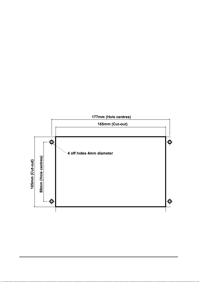
Dimensions
The Quantum3 should be installed by cutting a hole in the panel as detailed
below.
Page 17
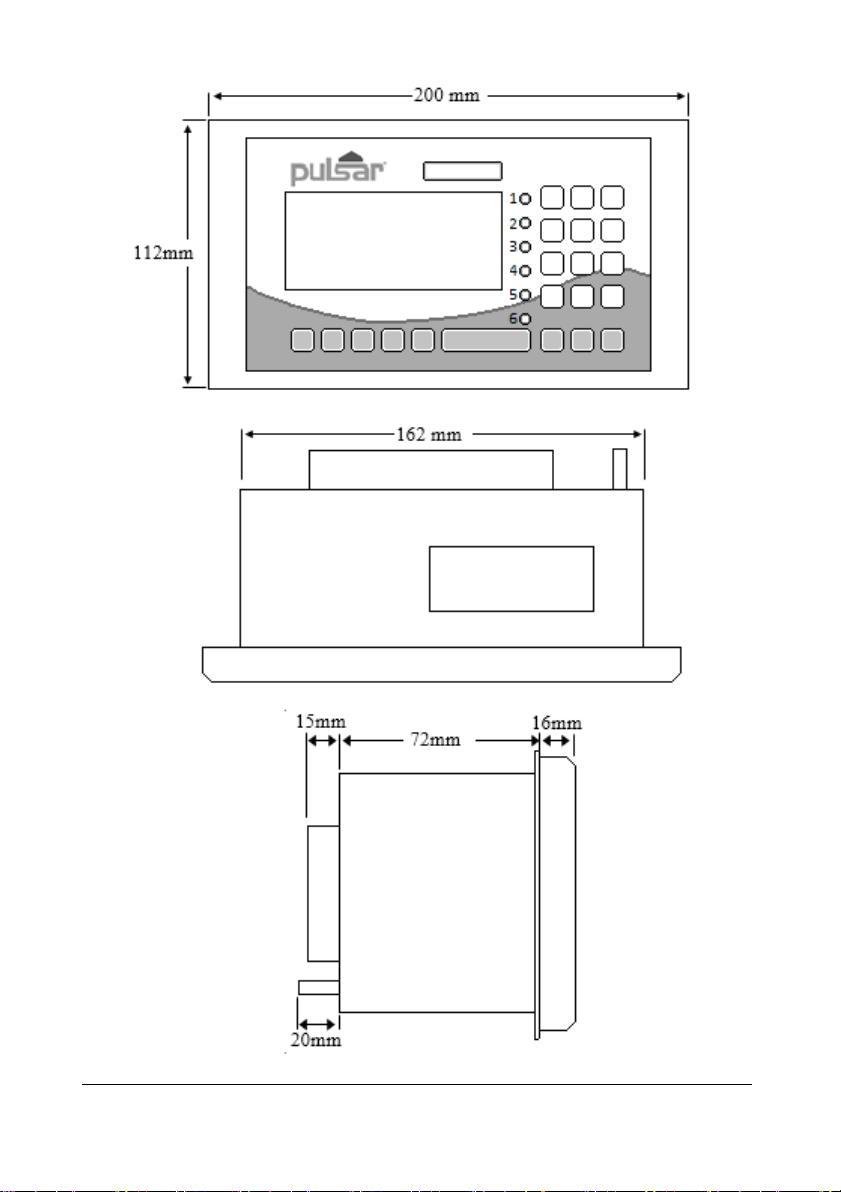
Page 9
The full dimensions of the enclosure are as shown below.
Page 18

Page 10
Terminal Connection Details
Power
The Quantum3 can operate from mains AC and automatically from DC or
battery backup in the event of power failure or can be operated permanently
from DC or batteries.
Transducer
The transducer should be installed, and connected, in accordance with the
installation instructions contained in the Transducer User Guide.
Wire the transducer to the Quantum3 transducer terminals, as follows:
Transducer
Terminal Connection Details
Red
Power
White
Signal
Black
0 volts
Green
Screen
32
31
30
30
When using 2-core screened extension cable, the Black and Green wires of
the transducer should be connected to the screen of the extension cable,
which in turn should be connected to the appropriate 0 volt terminal of the
Quantum3.
Page 19

Page 11
ATEX
For EEx m (Zone 1) applications a transducer certified to Sira
02ATEX5104X is used, and must be supplied via a 4000A breaking fuse,
which is fitted as standard to the Quantum3.
For EEx ia (Zone 0) a transducer certified to Sira 02ATEX2103X is used,
which must be connected to the Quantum3 via an external Zener barrier.
FM
For EEx m (Zone 1) applications a transducer certified to FM Class I Div 1
Group A, B, C & D, ClassII Div 1 Group E, F & G, Class III is used, and
must be supplied via a 1500A breaking fuse, which is fitted as standard to
the Quantum3.
Restrictions do not use in the presence of these groups of Chemicals,
Aliphatic Hydro Carbons, Ketones or Esters
For EEx ia (I.S.) a transducer certified to FM Class I Div 1 Group A, B, C
& D, ClassII Div 1 Group E, F & G is used, which must be connected to the
Quantum3via an external Zener barrier.
See transducer label for certification details.
Page 20

Page 12
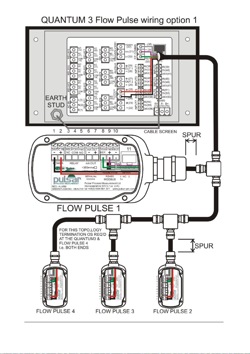
FlowPulse
When using the FlowPulse sensor, please use the FlowPulse manual for
specifics on how and where to setup the FlowPulse.
Flow pulse units are connected to a Quantum3 via a 5-core screened cable.
The cable screen should be connected to mains earth at the Quantum3 end
only.
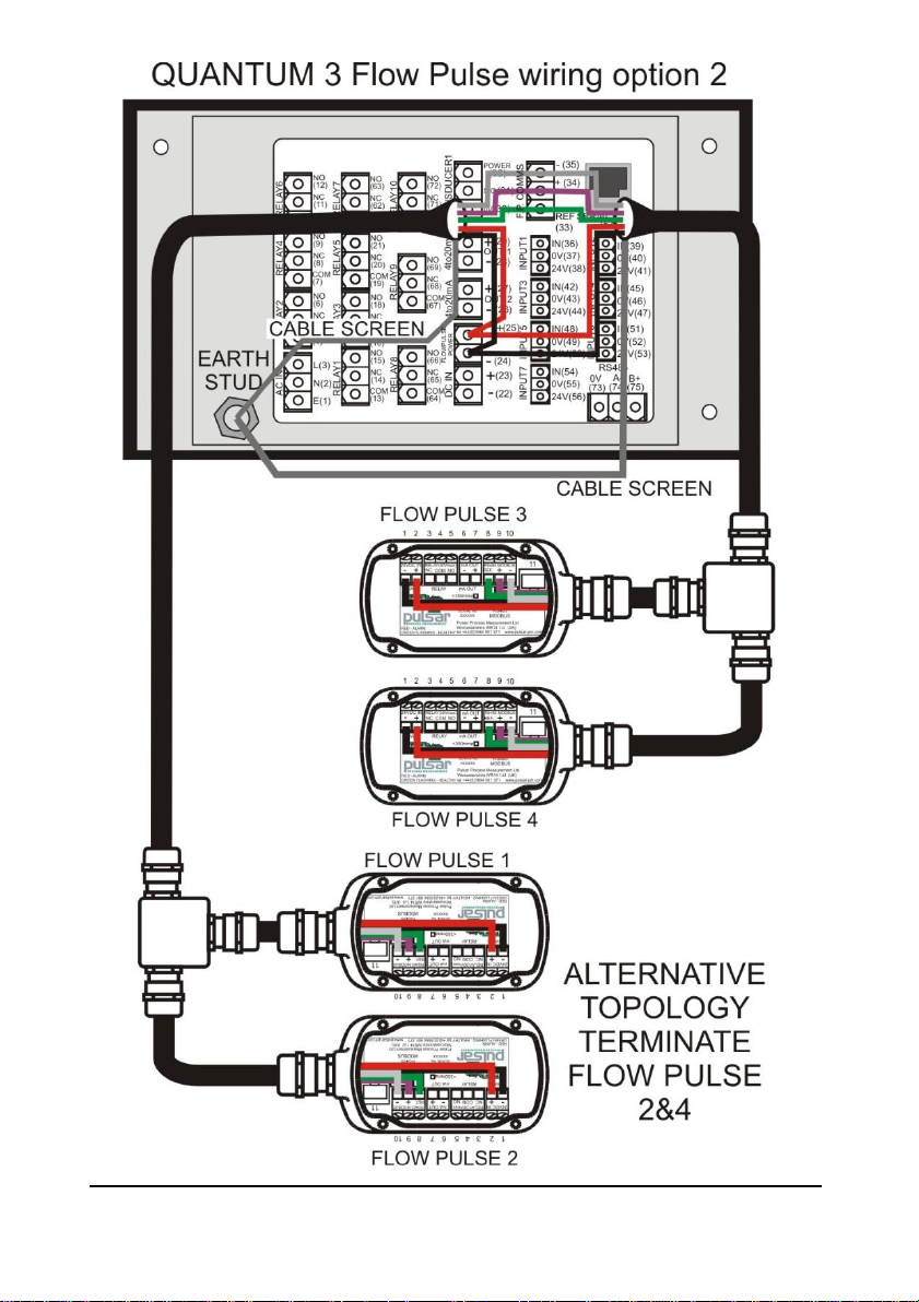
The wiring of the Flow Pulses should follow either wiring option 1 or 2.
You can connect 1 to 4 Flow Pulse units to the Quantum3.
The extreme ends of the Modbus cabling should be terminated with a 120R
resistor (this is achieved in FlowPulse via the termination switch). If
termination is required at the Quantum3 fit the included 120R resistor across
terminals 34 & 35.
The spurs to the FlowPulses should be kept as short as possible.
Wiring detail:
Description
Quantum3
Flow
Pulse 1
Flow
Pulse 2
Flow
Pulse 3
Flow
Pulse 4
Flow Pulse
Power
24VDC
25 1 1 1 1
0V
24 2 2 2 2
FlowPulse
comms +
34 9 9 9 9
FlowPulse
comms -
35
10
10
10
10
Return
33 8 8 8 8
Important Information
Termination – see following drawings.
Wiring Option 1- Switch on the termination of the last FlowPulse and fit
120R resistor (supplied) across terminals 34 & 35 of the Quantum3.
Wiring Option 2 – Switch on the termination of the FlowPulses at the
extreme ends i.e. FlowPulse 2 & 4.
Page 21
Page 13
Page 22
Page 14
Page 23

Page 15
Relay Outputs
The ten user definable relays can be programmed for a variety of alarms,
pump control, or other process functions. Relays 1, 2, 3 4 and 5 contacts are
all rated at 5A at 115V AC, whilst Relay 5, 6, 7, 8, 9 and 10 contacts are rated
at 3A at 115V AC. All connections should be such that the short circuit
capacity of the circuits to which they are connected, is limited by fuses rated
so that they do not exceed the relay rating.
Current Outputs
These are isolated (floating) mA outputs (to 150 V), of 4 - 20mA or 0 - 20mA
and the load should not exceed 500 .
Digital Inputs
Where the Quantum3 is required to provide power for a Device Input the
appropriate Digital Input should be wired between the 24VDC supply
terminal and the IN terminal. (TOTAL maximum current available, for all
seven digital inputs, from the 24VDC supply is 24mA). When Device Inputs
are self-powered, connection of the device should be made between the
Common terminal and the IN terminal. (Min Input voltage 4.5VDC, and
Maximum Input voltage 30VDC with a maximum current of 3mA).
RS232 Serial Interface
If required, you can connect to the serial interface, to operate your Quantum3
remotely.
Page 24
Page 16
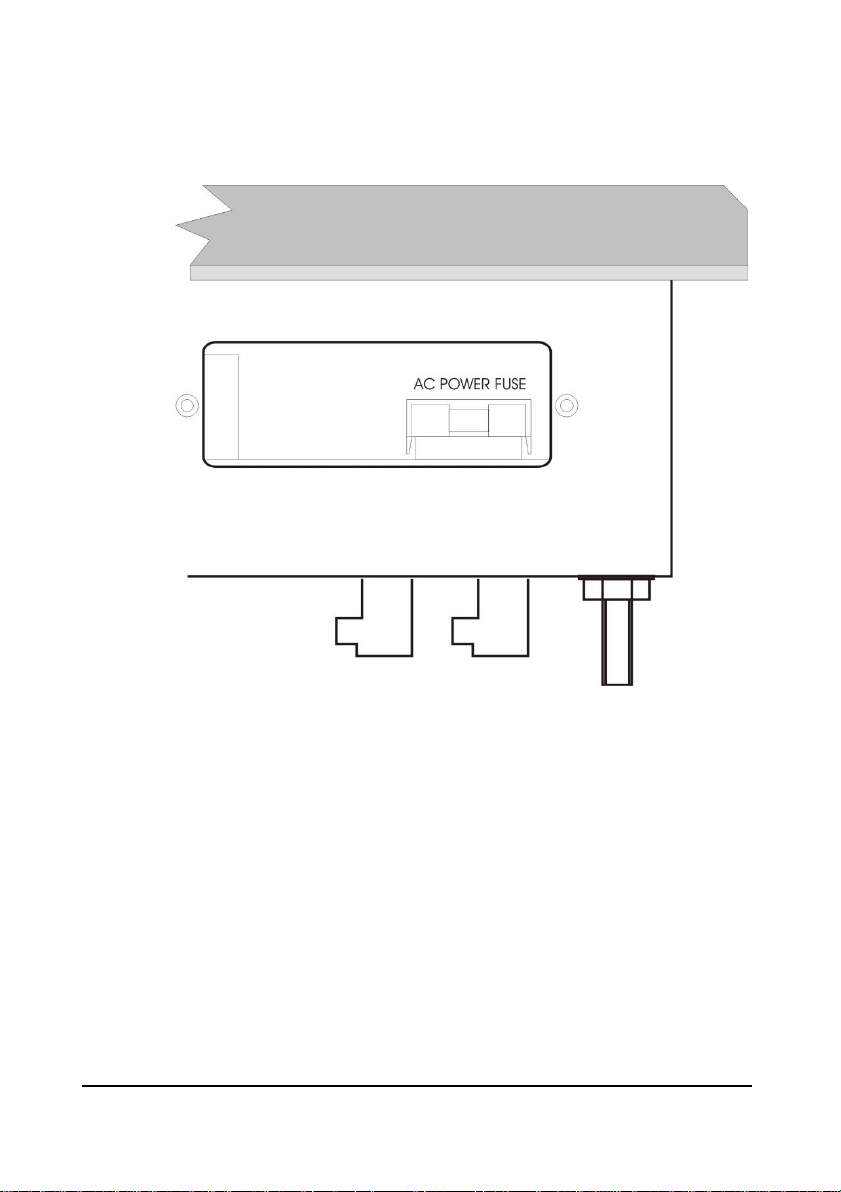
Fuse Location
The mains fuse is located under the removable cover at the bottom of the unit, as
illustrated below.
Page 25

Page 17
Important Information
The rear metal case of the fascia unit must be connected to earth via the
earthing stud located on the rear of the unit, see drawing above, using wiring
to meet local requirements.
An external switch or circuit breaker should be installed near to the
Quantum3 to allow the supply to be removed during installation and
maintenance. In addition, the relay contacts should also have a means of
isolating them from the unit.
Interconnecting cables must be adequately insulated in accordance with
local regulations. Strip back 30 mm of the outer insulation of the cable. Strip
5 mm of insulation from the end of each conductor. Twist all exposed
strands of the conductor together. Insert the stripped conductor into the
terminal block as far as it will go and tighten the terminal block screw.
Ensure that all strands are firmly clamped in the terminal block and that
there is no excess bare conductor showing, and no stray strands.
Important Information
If the equipment is installed or used in a manner not specified in this
manual, then the protection provided by the equipment may be impaired.
Page 26

Page 18
Preparation for Operation
Before switching on, check the following:
✓ The Quantum3 is mounted correctly and is in a ‘safe’ area.
✓ The power supply is correctly installed.
✓ The relays are connected correctly.
Maintenance
There are no user serviceable parts inside your Quantum3, except the mains
fuse. If you experience any problems with the unit, then please contact Pulsar
Process Measurement for advice.
To clean the equipment, wipe with a damp cloth. Do not use any solvents on
the enclosure or front panel.
Important Information
The unique DATEM software comes into operation as soon as power is
applied and is designed to monitor a moving level or target with the
transducer in a fixed position.
If, after any period of use, it should become necessary to move the
transducer, for any reason, from its original operating position, switch off
the Quantum3, before proceeding, to prevent any undesirable updates to the
DATEM trace. If after moving the transducer the reading is not as expected,
please refer to Chapter 6 Troubleshooting.
Page 27

Page 19
Chapter 3 How To Use Your Quantum3 Pump Controller
Quick Setup
If you are already familiar with the controls of the Quantum3, go straight to
the quick setup guide in Chapter 4.
Operating the Controls
Display
The display provides information on the current mode of operation, and status
of the remote communication. Whilst in the Run Mode it will display the
current level reading and its units of measure, along with status messages with
regards to the Transducer, Echo reception and Fail Safe Mode. Additionally,
it can be programmed to provide status messages on alarms, pumps etc. When
in the Program Mode the display is used to read information on the Menu
System, Parameter Number and parameter details and values, which can be
entered. During Test Mode the display is used to monitor the simulated level.
A bar graph is also provided which will provide a visual reading of the level,
in percentage of span.
Run Mode Program Mode Test Mode 100%
000.000
XXXXXXXXXXXX
REMOTE COMMUNICATOR OFF 0%
1 2 3 4 5
6
Page 28

Page 20
1) Mode status enunciator displays the current mode of operation.
2) Main 6-digit display:
Run Mode - current measurement displayed, dependent on mode and
measurement unit's chosen, and value of Hot Key function selected.
Program Mode - displays parameter number and values entered for
parameters.
Test Mode - displays simulated level.
3) Auxiliary Display (scrolling twelve digit display)
Run Mode - displays measurement units (P104), status messages on
signal and transducer and detail of Hot Key function selected. It can
also be programmed to provide notification messages on alarms, pumps
etc. (For full details please refer to Display Parameters in Chapter 5.)
Program Mode - displays Menu and Sub Menu headings, parameter
details and options.
4) Communicator status enunciator displays the current status of optional
remote PC connection.
5) Bargraph display gives visual indication of measurement in % of span.
6) Level indicators
Run Mode - indicates in which direction the level is moving.
Program Mode - indicates at which level, of the menu system, you are
currently at.
There are two main operating modes for your Quantum3, Run Mode and
Program Mode. There is also a Test Mode, used for checking the set-up. All
modes are now described.
Run Mode
This mode is used once the Quantum3 has been set up in program mode. It is
also the default mode that the unit reverts to when it resumes operation after
a power failure.
When the Quantum3 is switched on for the first time, it will display, in
metres, the distance from the transducer face to the target. All relays by
default are switched off.
After programming is complete, any relays that are set will operate when the
level reaches the relevant setpoint, and, in the case of relays 1, 2, 3, 4, 5 and
6, the LED’s will change colour (unless specifically switched off).
Page 29

Page 21
Program Mode
This mode is used to set up the Quantum3 or change information already set.
You must use either the built-in keypad (standard) or alternatively the unit
can be set up with a PC via the RS 232 Serial Interface (optional).
Entering a value for each of the parameters that are relevant to your
application provides all the programming information.
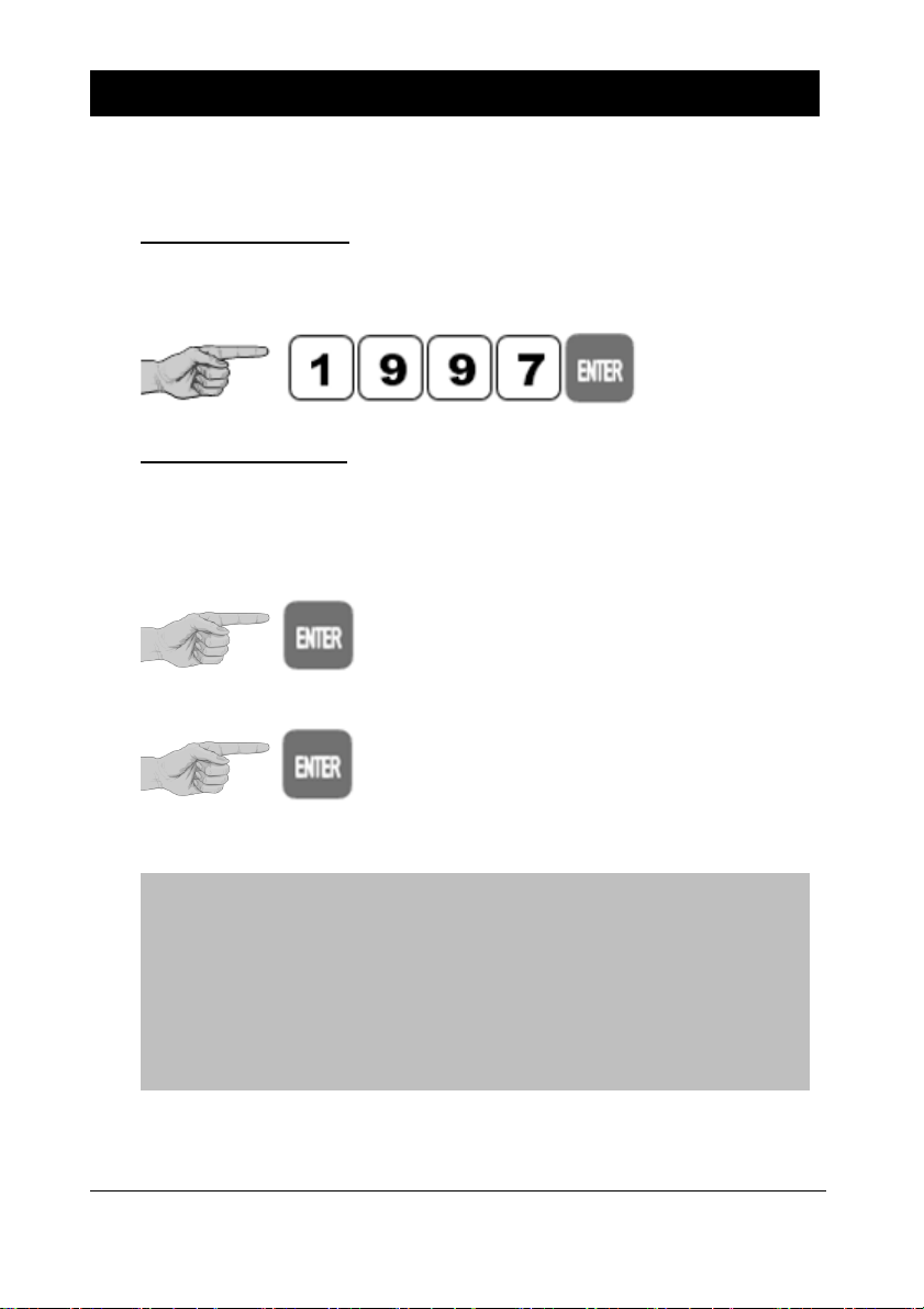
How to Access Program Mode
To enter program mode, you simply enter the passcode, via the keypad,
followed by the ENTER key. The default passcode is 1997, so you would
press the following:
Note
There is a time-out period of 15 minutes when in program mode, after
which time run mode will be resumed if you do not press any keys.
Page 30

Page 22
Hot Keys
There are five hot keys on the keypad, which can be used to quickly access
common parameters for viewing only, while in Run Mode. Pressing the hot
key once will display the first parameter, then repeated pressing will display
the others, after which the Quantum3 reverts to Run Mode. In Program Mode,
they have different functions, the functions are shown below.
Hot
Key
Run Mode
Program Mode
Total pump running hours, and
individual pump running hours.
Not used with Quantum3.
Displays echo confidence, echo
strength, H.A.L.L., average
noise, peak noise or
temperature.
Not used with Quantum3.
Total number of pump starts,
and individual pump starts.
Reset parameter to default
setting.
Instantaneous mA output.
Not used with Quantum3.
Dependant on application
displays Distance, Level, Space,
Volume or rate of change of
level.
Toggle relay setpoints
between Quantum3’s units
of measure and % of span.
Reset for Digital Inputs
Takes you to the last
parameter edited, when you
first enter program mode.
Gives details of unit type,
software revision and serial
number.
Enter decimal point
Page 31

Page 23
Menu Keys
The menu keys are used to navigate around the built-in menu system and have
the following functions:
Menu Key
Function
1) Arrow keys for moving left and right around the menu
system.
2) Used in test mode to simulate the level moving up and
down.
1) Used to confirm each action (for example select a
menu option) or when entering a parameter number or
value.
2) Used to confirm questions asked by your Quantum3
such as before restoring factory defaults.
Used to navigate up a level in the menu system, and back
to run mode.
Used to cancel a value entered in error.
Numeric Keys
These keys are used for entering numerical information during programming.
Page 32
Page 24
There are two means of editing parameters; directly or using the menu system.
Each is now described below.
Using the Menu System
The menu system has been designed to make the changing of parameters very
simple. There are two levels of menu: Main Menu and Sub Menu.
On the display there is a line of text that displays the menu system. Pressing
the arrow keys scrolls the display between the top-level menu items, as show
below in the “Quick Setup”.
As you press the cursor keys to scroll left and right, between these you can
press ENTER at any time to select it and take you to the sub-menu.
Each of these options, along with their sub-menus are described in Chapter 5,
Parameter Guide. When you move down into the sub-menu, you can scroll
round using the arrow keys, and press ENTER to go to the required section of
parameters.
Once you have reached the relevant section, scroll through the parameters,
and enter the necessary information. To enter the information, use the numeric
keys and press ENTER when you will see the message “Saved!" If you press
CANCEL, then the change you made will not be saved, and the message
“Unchanged!” will be displayed.
When you have finished, press CANCEL to go back to the previous level. When
you have reached the top level, then the Quantum3 will ask for confirmation
before allowing you to go back into run mode. This is done by pressing ENTER
at the display prompt.
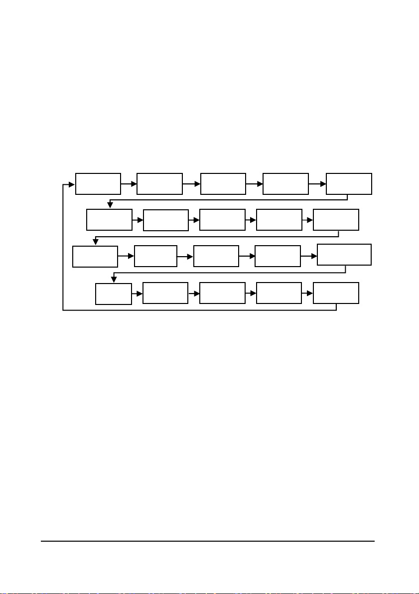
Quick Setup
Application
Relays
Pump
Advanced
Digital
Inputs
FS Backup
Data Logs
Display
mA
Output 1
Efficiency
FlowPulse
Compensation
Stability
System
Test
Device
Comm
Echo
Processing
mA
Output 2
Volume
Tariff Guard
Page 33

Page 25
Note
You can tell which part of the menu system you are in, as the up/down
indicators, (arrows) next to the bar graph will indicate as follows:
• Top level menu: Down arrow on, to indicate you can move down.
• Sub-menu: Up and Down arrows on, to indicate you can move up to
the top level, and down to parameter level.
• Parameter Level: Up arrow on, to indicate you can move up to sub-
menu level.
• Parameter Editing: No arrows on.
Directly Editing Parameters
If you already know the number of the parameter that you wish to look at or
edit, simply type the number in at any time while you are in the menu system.
Thus, if you are in either the menu or sub-menu level, by pressing a numeric
key you can enter the parameter number directly and jump straight there. You
cannot type a parameter number whilst at parameter level, only at one of the
two menu levels.
When you are at a parameter the text line rotates automatically displaying the
parameter name, number, the applicable units and the maximum and
minimum figure you can enter. The top line shows the value you are setting.
Once you have accessed a parameter you can either just look at it, or change
it.
Once a parameter has been changed, press ENTER and you will see the
message “Saved!” If you press CANCEL, then the change you made will not
be saved, and the message “Unchanged!” will be displayed.
TIP
You can jump straight to the last parameter you
edited, by pressing ‘+/-’ when you first enter
program mode.
Page 34

Page 26
Test Mode
Test mode is used to simulate the application and confirm that all parameters
and relay setpoints have been entered as expected. During simulation there is
a choice of whether the relays will change state (hard simulation) or not (soft
simulation), but the LED’s will always change colour as programmed, and
the mA output will change in accordance to the chosen mode of operation. If
you wish to test the logic of the system that the relays are connected to then
select hard simulation, but if you don’t want to change the relay state, then
select a soft simulation.
There are two simulation modes, automatic and manual. Automatic
simulation will move the level up and down between empty level or the predetermined Start Level (P983) and Pump/Control relay switch points, if you
wish to change the direction of the level movement e.g. to go beyond relay
setpoints, this can be done by using the arrow keys. In manual simulation,
using the arrow keys will allow you to move the level up and down as
required.
To enter simulation, first go to program mode. Then, using the menu system,
select menu item ‘Test’, then sub-menu item ‘Simulation’. Simply change
the value of the parameter P980 to one of the following:
1= Manual soft simulation
2= Automatic soft simulation
3= Manual hard simulation
4= Automatic hard simulation
To return to program mode, press CANCEL and test mode will end.
When in manual simulation, by default test mode will move the level by 0.1m
steps. Altering the increment (P981) will change this value.
In automatic mode, the rate at which the level moves up and down is set by
be changed to make the level move up and down faster. E.g. if increment
(P981) is set to 0.1m and rate (P982) is set to 1 min then the level will
increase or decrease at a rate of 0.1m/min. To make the simulated level move
slower, decrease the value in increment (P981) or increase the value in rate
(P982). To make the simulated level move faster, increase the value in
increment (P981) or decrease the value in rate (P982).
Whilst in Automatic hard simulation (P980 = 4) the switching of digital inputs
can be simulated by pressing the corresponding numeric key to the input to
be switched, each time the numeric key is pressed it will toggle the input
between On and Off.
Page 35

Page 27
Using the RS232 Serial Interface
The RS232 serial interface can be used to set up the Quantum3, and obtain
information using a PC or other computer equipment. To do so, the settings
for control are as follows: baud rate 19,200; 8 data bits; no parity; and 1 stop
bit.
The device should be connected via the serial port, as shown in Chapter 2
Installation.
To use the device remotely, you need to log on to start, and log off when
finished. When logged on, the Quantum3 will show ‘Remote ON’ on the
display, and “Communicator OFF” when logged off.
All commands should be followed by a carriage return.
The unit will respond either OK (or a value) if the command is accepted, or
NO if it is not. To log on, you send the command
/ACCESS:pppp where pppp is the passcode (P922).
To log off, you send the command
/ACCESS:OFF
To read a parameter value, send the command
/Pxxx where xxx is the parameter you wish to read, and the unit will respond
with the parameter value.
To set a parameter, send the command
/Pxxx:yy where xxx is the parameter number and yy is the value you wish to
set it to.
Other commands you can use are:
/DISTANCE (shows current distance)
/LEVEL (shows current level)
/SPACE (shows current space)
/VOLUME (shows current volume)
/RATE (shows current rate of change)
/TEMP (shows current temperature)
/CURRENTOUT (show the mA output value)
/CURRENTIN (show the mA input value)
/BACKUP1 (take backup of parameters to area 1)
/BACKUP2 (take backup of parameters to area 2)
/RESTORE1 (restore parameters from area 1)
/RESTORE2 (restore parameters from area 2)
Page 36

Page 28
Parameter Defaults
Factory Defaults
Factory Defaults
When first installing the Quantum3, or subsequently moving or using the
unit on a new application, before proceeding to program the unit for its
intended application it is recommended that you ensure that all parameters
are at their default values by completing a Factory Defaults P930, as
described in Chapter 5 Parameter Guide.
When you first switch the Quantum3 on, it will be reading the distance from
the face of the transducer to the surface (In the case of the mmWave radar the
distance is from the lens face to the surface). It will be indicating in metres,
as shown on the display. All relays are set OFF.
The date (P931) and time (P932) in the Quantum3 were set at the factory, but
may need checking, and amending if, for example the application is in a time
zone other than GMT, see Chapter 5 Parameter Guide for full details.
TIP
In some applications, it is simplest
to empty the vessel, take a reading
from the Quantum3 for distance and
then setup the empty level to this
figure.
Once you are satisfied with the installation, and the Quantum3 is reading what
you would expect in terms of distance from the face of the transducer to the
material level, then you can proceed with programming, for the intended
application. It is sensible to program all of the required parameters at the same
time. The system will be then set-up.
Note that the span is automatically calculated from the empty level, so the
empty level should be entered first.
Page 37
Page 29
Chapter 4 Quick Set-up Guide
This quick set-up guide shows you how to get up and running in a few minutes
in just four easy steps after installing your Quantum3.
Enter Program Mode
First you need to go from run mode into program mode. Assuming the
passcode is the default 1997, then you should enter this.
Choose Quick Setup
Now you need to go into the quick setup. You will see on the menu the words
‘Quick Setup’, which is the first item on the menu system. Try pressing the
two arrow keys to see some more menu options, but return to Quick Setup,
and press
This takes you to the common applications
parameter (P200).
This takes you to the common applications
parameters, and you will see some options
appearing on the display.
Note
If you have already setup a common application, then there will be a number
shown other than 0, and you will see messages showing what the current
setup is. If you want to reset this and start again, press 0 (which will reset all
the quick setup parameters), otherwise pressing ENTER will allow you to edit
the parameters that have been set.
Page 38

Page 30
Choose Your Application
There are four categories of application, which are all described at the end of
this chapter. They are level, pump down (sump control), pump up (reservoir
control) or customised, all with the choice of alarms and a number of pumps,
dependant on application.
If you want to set-up a basic level monitoring application, as described in the
following example 1, then choose 1. You then need to decide the number of
alarms required and their function and choose the appropriate options.
If you want to set-up a pump down (sump control) application, as described
in the following example 2, then choose 2. You then need to decide the
number of pumps required the pump duty and any requirement for alarms
and choose the appropriate options.
If you want to set-up a pump up (reservoir control) application, then choose
3. You then need to decide the number of pumps required the pump duty,
and any requirement for alarms, and choose the appropriate options.
In certain cases, the Quick Setup Menu has been customised for particular
customer specific applications, to choose one of these options press 4 and
select the appropriate customised application and enter the details required as
prompted.
Once you have chosen your application you will be asked a series of questions
which are answered by choosing the appropriate option as detailed in the flow
charts that follow. Once all the questions have been answered you will be
prompted to provide further information, as detailed in the tables that follow,
in order to complete the programming of the unit.
Page 39

Page 31
The Quick Setup Menu detailing the questions you are asked, when setting up
your Quantum3, via the Quick Setup is shown below.
Quick Setup Menu
Quick Setup
1 = Level
4=Customised
2=Pump Down
3=Pump Up
How Many Pumps
0 = No Pumps
1 = One Pump
2 = Two Pumps
3 = Three Pumps
4 = Four Pumps
5 = Five Pumps
6 = Six Pumps
Pump Duty
1=Fixed Duty assist
2=Fixed Duty Backup
3=Alt Duty Assist
4=Alt Duty Backup
5=Duty Backup & Ass
6 = Serv Ratio Duty Ass
7=Serv Ratio Duty Bup
8=FOFO Alt Duty Ass
For Each Pump Relay
1 = Set to Relay 1
2 = Set to Relay 2
3 = Set to Relay 3
4 = Set to Relay 4
5 = Set to Relay 5
6 = Set to Relay 6
7 = Set to Relay 7
8 = Set to Relay 8
9 = Set to Relay 9
0 = Set to Relay 10
How Many Alarms
0 = No Alarms
1 = One Alarm
2 = Two Alarm
3 = Three Alarm
4 = Four Alarm
5 = Five Alarm
6 = Six Alarms
7 = Seven Alarms
8 = Eight Alarms
9 = Nine Alarms
10 = Ten Alarms
List will be truncated
according to the number
of pumps selected
For Each Alarm
1 = High Alarm
2 = Low Alarm
3 = Hi Hi Alarm
4 = Lo Lo Alarm
5 = Loss of Echo
For Each Alarm
1 = Set to Relay 1
2 = Set to Relay 2
3 = Set to Relay 3
4 = Set to Relay 4
5 = Set to Relay 5
6 = Set to Relay 6
7 = Set to Relay 7
8 = Set to Relay 8
9 = Set to Relay 9
0 = Set to Relay 10
Select the
option specific
to your
Application
Page 40

Page 32
Note
The maximum number of relays that can be allocated, via the Quick Setup,
for use as ‘alarms’ or ‘pump’ is six, if you require to allocate additional
relays to ‘alarms or ‘pump’ this can be achieved by accessing the Relay
Menu and programming additional relays as required.
Set-up Your Application
Once you have chosen the application, you will see a ‘Wait…’ message while
the parameters are all calculated and stored. Next you will see the parameters
needed to finalise your application, in turn, as shown below. If you know you
don’t need to change from the default, you can use the right arrow key to
scroll through them, but if you want to view or change each one, just press
ENTER.
Parameter
Default
Description
P101 Transducer
2 = dB6
Type of transducer being used.
P104
Measurement
Units
1 = metres
Select units to be used for
programming measurement
information.
P105
Empty Level
6 m
Distance from the face of the
transducer to the material at the
bottom of the vessel.
P106
Span
5.7 m
Distance from the empty level (0%
full) to span (100% full).
For More Options Hit Enter
Now you will see a scrolling message that says ‘For more Options Hit Enter’.
If you press ENTER, you will then see more parameters, specific to the
application you have chosen, these are all factory preset. If you press any other
key you will return to the Quick Setup menu, where you can press CANCEL to
return to run mode.
Page 41

Page 33
If you want to change any of the factory preset parameters, then you can do
so, referring to the relevant page of Chapter 5, in this handbook for detailed
information. The parameters concerned are shown below.
Parameter
Default
Description
P213 / P214
Relay 1
ON/OFF
setpoints
Factory preset as a % to
appropriate level according
to the span already entered.
See tables below
Either Alarm or Level
control. Depends on
application.
P223 / P224
Relay 2
ON/OFF
setpoints
Factory preset as a % to
appropriate level according
to the span already entered.
See tables below
Either Alarm or Level
control. Depends on
application.
P233 / P234
Relay 3
ON/OFF
setpoints
Factory preset as a % to
appropriate level according
to the span already entered.
See tables below
Either Alarm or Level
control. Depends on
application.
P243 / P244
Relay 4
ON/OFF
setpoints
Factory preset as a % to
appropriate level according
to the span already entered.
See tables below
Either Alarm or Level
control. Depends on
application.
P253 / P254
Relay 5
ON/OFF
setpoints
Factory preset as a % to
appropriate level according
to the span already entered.
See tables below
Either Alarm or Pump
control. Depends on
application.
P263 / P264
Relay 6
ON/OFF
setpoints
Factory preset as a % to
appropriate level according
to the span already entered.
See tables below
Either Alarm or Level
control. Depends on
application.
P830
mA Out Range
2= 4 to 20 mA
Determines the mA
output range.
0 = Off, 1 = 0 to 20mA,
2 = 4 to 20mA, 3
= 20 to 0mA, 4 = 20 to
4mA.
P870
Fill Damping
10 m/min
Rate of maximum fill
rate (set above the
actual fill rate of the
P871
Empty
Damping
10 m/min
Rate of maximum
empty rate (set above
the actual empty rate of
the vessel).
Page 42

Page 34
The default values used for determining the relay setpoints, when setting
alarms and pumps, via the Quick Setup menu are entered as a % of span and
are as follows.
Application
Number
of
Pumps
Pump
Number
On
Setpoint
Off
Setpoint
Pump Down
One
Pump 1
50%
20%
Pump Down
Two
Pump 1
Pump 2
50%
70%
20%
20%
Pump Down
Three
Pump 1
Pump 2
Pump 3
50%
60%
70%
20%
20%
20%
Pump Down
Four
Pump 1
Pump 2
Pump 3
Pump 4
40%
50%
60%
70%
20%
20%
20%
20%
Pump Down
Five
Pump 1
Pump 2
Pump 3
Pump 4
Pump 5
40%
50%
60%
70%
75%
20%
20%
20%
20%
20%
Pump Down
Six
Pump 1
Pump 2
Pump 3
Pump 4
Pump 5
Pump 6
40%
50%
60%
70%
75%
80%
20%
20%
20%
20%
20%
20%
Page 43

Page 35
Application
Number
of
Pumps
Pump
Number
On
Setpoint
Off
Setpoint
Pump Up
One
Pump 1
50%
80%
Pump Up
Two
Pump 1
Pump 2
50%
30%
80%
80%
Pump Up
Three
Pump 1
Pump 2
Pump 3
50%
40%
30%
80%
80%
80%
Pump Up
Four
Pump 1
Pump 2
Pump 3
Pump 4
60%
50%
40%
30%
80%
80%
80%
80%
Pump Up
Five
Pump 1
Pump 2
Pump 3
Pump 4
Pump 5
60%
50%
40%
30%
25%
80%
80%
80%
80%
80%
Pump Up
Six
Pump 1
Pump 2
Pump 3
Pump 4
Pump 5
Pump 6
60%
50%
40%
30%
25%
20%
80%
80%
80%
80%
80%
80%
Relay
Function
Relay I.D.
On
Setpoint
Off
Setpoint
Alarm
HiHi
90%
85%
Alarm
High
85%
80%
Alarm
Low
10%
15%
Alarm
LoLo
5%
10%
Page 44

Page 36
Example 1 Level Control
A vessel, containing liquid that has a variation in level that is to be monitored,
with a high-level alarm set on Relay 1 and low level alarm set on Relay 2.
empty distance (P105), 3.5m
100%, span (P106), 2.8m
85% , high alarm on (P213), 2.38m
80% , high alarm off (P214), 2.24m
15% , low alarm off (P224), 0.42m
10% , low alarm on (P223), 0.28m
0% , empty level
In this example, when the level rises to 2.38 m, relay 1 will come on until the
level drops to 2.24 m when it will turn off. If the level drops to 0.28 m, then
relay 2 will come on until it rises 0.42 m when it will turn off.
The display will show the level in the tank.
The mA output will be representative of level where 4mA = empty level (0%)
and 20mA = 2.8m (100%)
Page 45

Page 37
To program the Quantum3 for Example 1 Level Monitoring with Alarms
by using the Quick Setup menu proceed as follows.
If required access the Program Mode
Key in the passcode 1997 and press ENTER
At the Quick Setup menu press ENTER and as prompted, by the questions,
select the relevant option and ENTER.
Question
Option
Level/Pump/Custom
1= Level App.
No. of Alarms
2= 2 Alarms
Type Alarm 1
1= High
Alarm No 1
1 = Set Relay 1
Type Alarm 2
2= Low
Alarm No 2
2 = Set Relay 2
Xducer (P101)
2= dB6
Material (P102)
1 = Liquid
Measnt Units (P104)
1 = metres
Empty Level (P105)
3.5 (metres)
Span (P106)
2.8 (metres)
Programming is now complete and the unit can be returned to the run mode,
press CANCEL until Run Mode? Is displayed on the LCD press ENTER,
and the Quantum3 will return to the Run Mode.
Note
If relay setpoints do not meet the exact requirements of the application, they
can be modified to suit by pressing ENTER when, “For More Options Hit
Enter”, is displayed, and entering new values to relay setpoints as required.
Alternatively, the relevant relay setpoint can be accessed either by the main
menu system or directly via parameter number and changed as necessary.
Page 46

Page 38
Example 2 Sump Control (pump down)
A sump is typically used to temporarily hold water or effluent, and when the
level reaches a specific point, the sump is pumped down, with the fluid being
transferred to another process.
empty distance (P105), 3.5m
100%, span (P106), 2.8m
85% , high alarm on (P253), 2.38m
80% , high alarm off (P254), 2.24m
20%, pump 1+2 off (P214, 224), 0.56m
0% , empty level
50%, pump 1 on (P 223), 1.4m
70%, pump 2 on (P 213), 1.96m
---
In this example, there are two pumps, which will be set to alternate duty assist,
so they come on alternately. Pump 1 is to be set to Relay 1, Pump 2 to Relay
2, and the high-level alarm to Relay 5.
This will operate as follows. During normal operation, pump 1 will come on
at 1.4 m, and pump down to 0.56 m. The setpoints are then shifted to pump
2, which will come on first next time.
During peak periods, when pump 1 cannot cope, pump 1 will come on at 1.4
m, pump 2 will come on at 1.96 m, and pump down to 0.56 m. The setpoints
are then shifted to pump 2, which will come on first next time.
If neither pump can cope, and the level rises to 2.38 m, then the alarm relay
(relay 5) will come on, and go off when the level falls to 2.24 m. This will
indicate insufficient capacity of the pumps.
The display will show the level in the sump and the mA output will be
representative of level where 4mA = empty level (0%) and 20mA = 2.9m
(100%).
Page 47

Page 39
To program the Quantum3 for Example 2 Sump control (pump down) by
using the Quick Setup menu proceed as follows.
If required access the Program Mode
Key in the passcode 1997 and press ENTER
At the Quick Setup menu press ENTER and as prompted, by the questions,
select the relevant option and ENTER.
Question
Option
Level/Pump/Custom
2=Pump Down
No. of Pumps
2=2 Pumps
Pump Duty
3=Alt DutAss
Pump No 1
1 = Set Relay 1
Pump No 2
2 = Set Relay 2
No. of Alarms
1=1 Alarms
Type Alarm 1
1=High Alarm
Alarm No 1
5 = Set Relay 5
Xducer (P101)
2=dB6
Measnt Units (P104)
1 = metres
Empty Level (P105)
3.5 (metres)
Span (P106)
2.8 (metres)
Programming is now complete and the unit can be returned to the run mode,
press CANCEL until Run Mode? Is displayed on the LCD press ENTER,
and the Quantum3 will return to the Run Mode.
Note
If relay setpoints do not meet the exact requirements of the application, they
can be modified to suit by pressing ENTER when, “For More Options Hit
Enter”, is displayed, and entering new values to relay setpoints as required.
Alternatively, the relevant relay setpoint can be accessed either by the main
menu system or directly via parameter number and changed as necessary.
Page 48

Page 40
This page left blank intentionally
Page 49
Page 41
Chapter 5 Parameter Guide
This chapter outlines all parameters available in the Quantum3, as they appear
in the menu system.
Menu System Diagrams
Shown below is a set of charts to show you how all the various parts can be
found using the menu system.
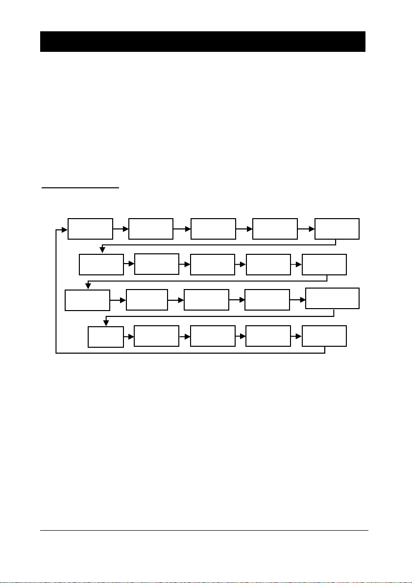
Top Level Menu
Quick Setup
Application
Relays
Pump
Advanced
Digital
Inputs
FS Backup
Data Logs
Display
mA
Output 1
Efficiency
FlowPulse
Compensation
Stability
System
Test
Device
Comm
Echo
Processing
mA
Output 2
Volume
Tariff Guard
Page 50
Page 42
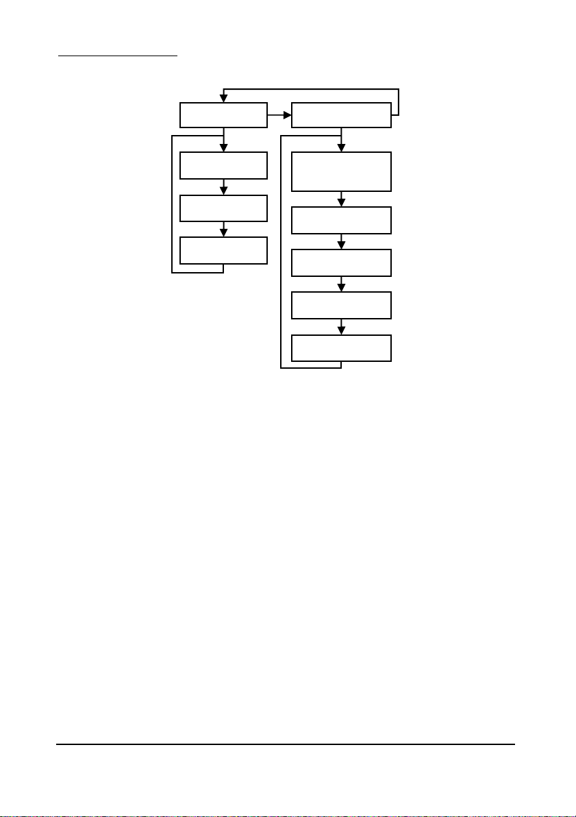
Application Menu
Operation
Distances
P100
Mode
P101
Transducer
P104
Measurement
Units
P102
Material
P105
Empty Level
P106
Span
P107
Near Blanking
P108
Far Blanking
Page 51
Page 43
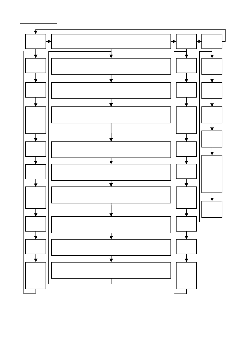
Relays Menu
Pump
Trips
P307
Trip
Limit
P311
to
P318
Pump 2
to
Pump 9
Trips
P310
Pump 1
Trip
P309
Reset
Pulse
P308
Reset
Int.
P319
Pump 10
Trip
Relay
1
Relay
10
Relay 2 to Relay 9
Rly 2 – P220, Rly 3 – P230, Rly 4 – P240, Rly 5 – P250
Rly 6 – P260, Rly 7 – P270, Rly 8 – P280, Rly 9 – P290
Type
P210
Type
P570
Type
P211
Function
P213
Set 1
P212
Alarm ID
or
Pump
Group
P214
Set 2
P215
Set 3
as
required
P217
Closures
P218
Fail Safe
P219
R1
Max
Rate if
P210 = 2
Rly 2 – P221, Rly 3 – P231, Rly 4 – P241, Rly 5 – P251
Rly 6 – P261, Rly 7 – P271, Rly 8 – P281, Rly 9 – P291
Function
Rly 2 – P222, Rly 3 – P232, Rly 4 – P242, Rly 5 – P252
Rly 6 – P262, Rly 7 – P272, Rly 8 – P282, Rly 9 – P292
Alarm ID or Pump Group
Rly 2 – P223, Rly 3 – P233, Rly 4 – P243, Rly 5 – P253
Rly 6 – P263, Rly 7 – P273, Rly 8 – P283, Rly 9 – P293
Relay Setpoint 1
Rly 2 – P224, Rly 3 – P234, Rly 4 – P244, Rly 5 – P254
Rly 6 – P264, Rly 7 – P274, Rly 8 – P284, Rly 9 – P294
Relay Setpoint 2
Rly 2 – P225, Rly 3 – P235, Rly 4 – P245, Rly 5 – P255
Rly 6 – P265, Rly 7 – P275, Rly 8 – P285, Rly 9 – P295
Relay Setpoint 3 as required
Rly 2 – P227, Rly 3 – P237, Rly 4 – P247, Rly 5 – P257
Rly 6 – P267, Rly 7 – P277, Rly 8 – P287, Rly 9 – P297
Relay Closures
Rly 2 – P228, Rly 3 – P238, Rly 4 – P248, Rly 5 – P258
Rly 6 – P268, Rly 7 – P278, Rly 8 – P288, Rly 9 – P298
Fail Safe
Rly 2 – P229, Rly 3 – P239, Rly 4 – P249, Rly 5 – P259
Rly 6 – P269, Rly 7 – P279, Rly 8 – P289, Rly 9 – P299
Max Rate if P2*0 = 2
P571
Function
P572
Alarm ID
or
Pump
Group
P573
Set 1
P574
Set 2
P575
Set 3
as
required
P577
Closures
P578
Fail Safe
P579
R1
Max
Rate if
P570 = 2
Page 52
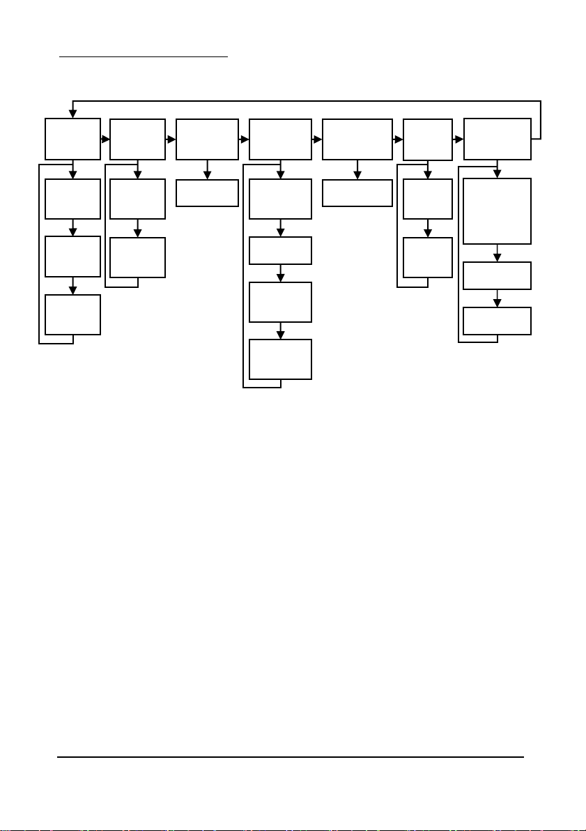
Page 44
Pump “Advanced” Menu
Stopping
Wall Cling
P348
Stop Delay
P360
Wall Cling
Run On
P349
Prime
Level
P350
Run
Interval
P351
Run
Duration
Starting
P352
Start
Delay
P353
Power
Delay
Exercise
P354
Exercise
Enable
P355
Idle Time
P356
Exercise
Time
P357
Minimum
Head
Storm
P370
Pump
Disable
P371
Disable
Time
Rate
Method
P116
Rate Calc
When
P118 = 1
Derived
P117
RMA Delay
P118
Output Flow
Page 53
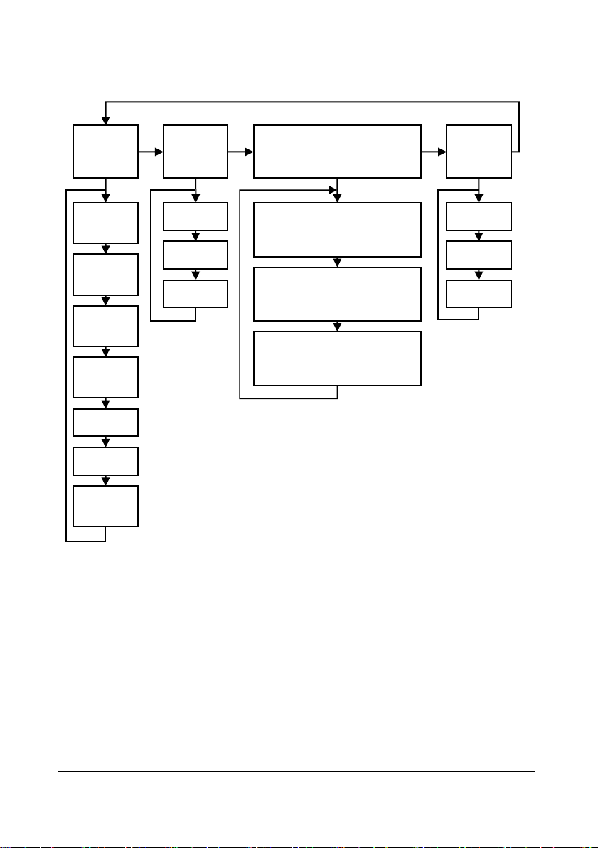
Page 45
Digital Inputs Menu
Common
Par
Digital
Input 1
P300
Maximum
Attempts
P301
Switch
Mode
P302
Override
Delay
P303
Minimum
Override
P304
Input Delay
P305
Input Filter
P306
Override
Level
P372
Type
P373
Function
P374
Assign.
Input 2 – P375, Input 3 – P378
Input 4 – P381, Input 5 – P384
Input 6 – P387
Type
Digital Input 2
to
Digital Input 6
Input 2 – P376, Input 3 – P379
Input 4 – P382, Input 5 – P385
Input 6 – P388
Function
Input 2 – P377, Input 3 – P380
Input 4 – P383, Input 5 – P386
Input 6 – P389
Assign.
Digital
Input 7
P390
Type
P391
Function
P392
Assign.
Page 54
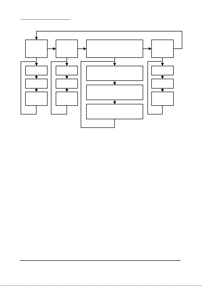
Page 46
Float Switch Backup
Common
Par
Digital
Input 1
P330
Mode
P331
Input Filter
P332
Pump Run
Time
P333
Type
P334
Function
P335
Forced
Level
Input 2 – P336, Input 3 – P339
Input 4 – P342, Input 5 – P345
(Type)
Digital Input 2
to
Digital Input 5
Input 2 – P337, Input 3 – P340
Input 4 – P343, Input 5 – P346
(Function)
Input 2 – P338, Input 3 – P341
Input 4 – P344, Input 5 – P347
(Forced Level)
Digital
Input 6
P363
Type
P364
Function
P365
Forced
Level
Page 55
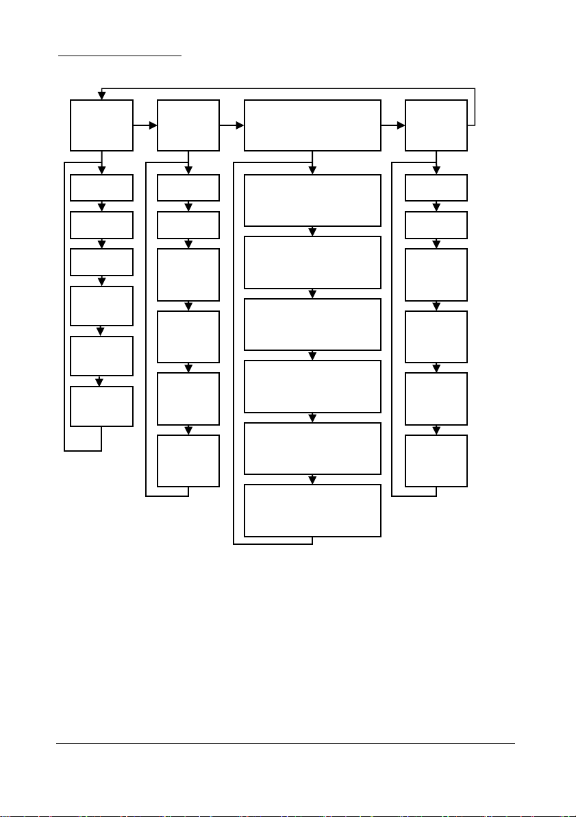
Page 47
Tariff Guard Menu
Set Up
Peak
Time
1
Peak Time 2
to
Peak Time 9
PT2 – P406, PT3 – P412,
PT4 – P418, PT5 – P424,
PT6 – P430, PT7 - P436,
PT8 – P443, PT9 – P448,
Peak
Time
10
PT2 – P407, PT3 – P413,
PT4 – P419, PT5 – P425,
PT6 – P431, PT7 - P437,
PT8 – P444, PT9 – P449,
PT2 – P408, PT3 – P414,
PT4 – P420, PT5 – P426,
PT6 – P432, PT7 - P438,
PT8 – P445, PT9 – P450,
PT2 – P409, PT3 – P415,
PT4 – P421, PT5 – P427,
PT6 – P433, PT7 - P439,
PT8 – P446, PT9 – P451,
PT2 – P410, PT3 – P416,
PT4 – P422, PT5 – P428,
PT6 – P434, PT7 - P440,
PT8 – P447, PT9 – P452,
PT2 – P411, PT3 – P417,
PT4 – P423, PT5 – P429,
PT6 – P435, PT7 - P441,
PT8 – P448, PT9 – P453,
P393
Enable
P394
Lead Time
P395
Lag Time
P396
Minimum
Pump Time
P398
Overflow
Level
P400
PT1 Day
P401
PT1 Week
P402
PT1
Start Peak
(Date)
P403
PT1
End Peak
(Date)
P404
PT1
Start
(Time)
P405
PT1
End
(Time)
P454
PT1 Day
P455
PT1 Week
P456
PT1
Start Peak
(Date)
P457
PT1
End Peak
(Date)
P458
PT1
Start
(Time)
P459
PT1
End
(Time)
P397
Minimum
Head
Page 56
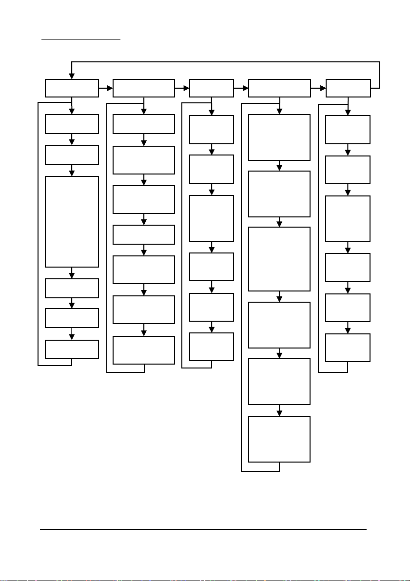
Page 48
Data Logs Menu
P511
Pump 1
Starts
Tot. Audit
Temperature
Pump 1
Pump 2 to 9
Pump 10
P516, P522
P528, P534
P540, P546
P552, P558
Pump Hours
P517, P523
P529, P535
P541, P547
P553, P559
Pump Starts
P518, P524
P530, P536
P542, P548
P554, P560
Pump Starts
per
Hour
P519, P525
P531, P537
P543, P549
P555, P561
Pump Run On
P460
Vol. Date 1
P461
Volume 1
P462, 464,
466, 468, 470,
472, 474, 476
Total Dates
2 to 9
P463, 465,
467, 469, 471,
473, 475, 477
Totals
2 to 9
P478
Vol. Date 10
P580
Min. Temp
P479
Volume 10
P581
Min. Temp.
Date
P582
Min. Temp.
Time
P583
Max. Temp.
P584
Max. Temp.
Date
P585
Max. Temp.
Time
P586
Current
Temperature
P510
Pump 1
Hours
P512
Pump 1
Starts
per
Hour
P513
Pump 1
Run On
P564
Pump 10
Hours
P565
Pump 6
Starts
P566
Pump 10
Starts
per
Hour
P567
Pump 10
Run On
P514
Pump 1
Draw
P515
Pump 1
Effic.
P520, P526
P532, P538
P544, P550
P556, P562
Pump Draw
P521, P527
P533, P539
P545, P551
P557, P563
Pump Effic.
P568
Pump 10
Draw
P569
Pump 10
Effic.
P480
Clear Logs
Page 57
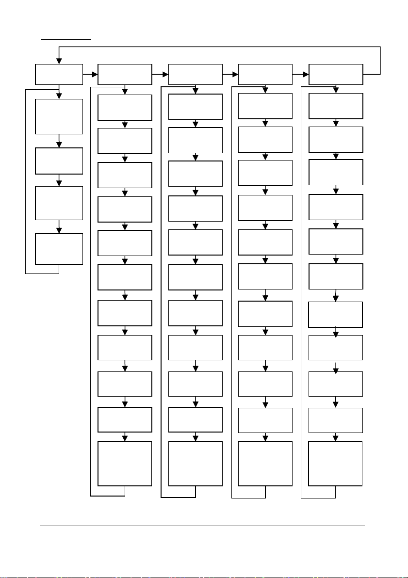
Page 49
FlowPulse
P1161 –
P1165
Totaliser1 –
Totaliser5
P1141 –
P1145
Totaliser1 –
Totaliser5
P1181 –
P1185
Totaliser1 –
Totaliser5
P1201 –
P1205
Totaliser1 –
Totaliser5
General
P1110
Volume
Units
P1111
Time Units
P1112
Flow
Decimal
P1113
Clear Logs?
FP1 Setup
FP2 Setup
FP3 Setup
FP4 Setup
P1130
Address
P1150
Address
P1170
Address
P1190
Address
P1131
Allocation
P1151
Allocation
P1171
Allocation
P1191
Allocation
P1132
Diameter
P1152
Diameter
P1172
Diameter
P1192
Diameter
P1133
Pipe Type
P1153
Pipe Type
P1173
Pipe Type
P1193
Pipe Type
P1134
Density
P1154
Density
P1174
Density
P1194
Density
P1135
Damping
P1155
Damping
P1175
Damping
P1195
Damping
P1137
MagThreshold
P1157
MagThreshold
P1177
MagThreshold
P1197
MagThreshold
P1138
SR Mode
P1158
SR Mode
P1178
SR Mode
P1198
SR Mode
P1139
SR Threshold
P1159
SR Threshold
P1179
SR Threshold
P1199
SR Threshold
P1140
Track Method
P1160
Track Method
P1180
Track Method
P1200
Track Method
Page 58

Page 50
Pumped Volume Menu
Set Up
P205
Pump Vol.
Enabled
P206
Settle Time
P207
Inflow
Method
Conversion
P600
Vessel Shape
P601
As Required
Vol. Dimension 1
P602
As Required
Vol. Dimension 2
P603
As Required
Vol. Dimension 3
P604
Calculated
Volume
P605
Volume Units
P606
Correct. Factor
P607
Max. Volume
P612, 614, 616, 618,
620, 622, 624, 626,
628, 630, 632, 634,
636, 638, 640, 642,
644, 646, 648, 650,
652, 654, 656, 658,
660, 662, 664, 666,
668, 670
Level Bkpts. 2 to 31
Breakpoints
P610
Level Bkpt. 1
P611
Vol. Bkpt. 1
P613, 615, 617, 619,
621, 623, 625, 627,
629, 631, 633, 635,
637, 639, 641, 643,
645, 647, 649, 651,
653, 655, 657, 659,
661, 663, 665, 667,
669, 671
Vol. Bkpts. 2 to 31
P672
Level Bkpt. 32
P673
Vol. Bkpt. 32
Tables
P696
Reset
Bkpts.
P697
Number
Bkpts. Set
Page 59

Page 51
Efficiency Menu
Set Up
P187
Pump Effic.
P188
Calib. Delay
P189
Cal. Duration
P190
Persist Cnt.
P191
Demote
Pumps
P192
Demote
Flags
P193
Calib. Pumps
Page 60

Page 52
Display Menu
Options
Fail Safe
Auxiliary
P802
Display
Offset
P801
Decimal
Places
P804
Display
Conversion
P808
Fail Mode
P809
Fail Time
P810
Units
P811
Alarms
P812
Pumps
P813
Control
P814
Misc.
P816
Totaliser
(R)
P817
Auxiliary
Offset
Totaliser
P820
Totaliser
P821
Totaliser (R)
P822
Totaliser
Decimal
P823
Totaliser
Multiplier
P800
Display
Units
Page 61

Page 53
mA Output 1 Menu
mA Output 2 Menu
Operation
Setpoint
Limits
Trim
Fail Safe
P831
mA Out
Mode
P834
Low
Value
P836
Low
Limit
P835
High
Value
P837
High
Limit
P838
Low
mA
Trim
P839
High
mA
Trim
P840
Fail
Mode
Range
P830
mA Out
Range
Range
P890
mA2
Out
Range
Operation
Setpoint
Limits
Trim
Fail Safe
P891
mA2 Out
Mode
P892
Low
Value
P894
Low
Limit
P893
High
Value
P895
High
Limit
P896
Low
mA
Trim
P897
High
mA
Trim
P898
Fail
Mode
Page 62

Page 54
Compensation Menu
Stability Menu
Offset
Temperature
Velocity
P851
Measurement
Offset
P852
Temperature
Source
P854
Fixed
Temperature
P860
Sound
Velocity
OVF Count
P865
OVF
Count
Damping
Indicator
Rate
Filters
P870
Fill
Damping
P871
Empty
Damping
P872
Fill
Indicator
P873
Empty
Indicator
P874
Rate Update
P875
Rate Time
P876
Rate Distance
P877
Rate Value
P878
Lower Cutoff
P880
Gate Mode
P881
Fixed Distance
P884
Peak Percent
Page 63

Page 55
Echo Processing Menu
Xdr. 1 Status
P900
Xdr. 1 Status
P901
Echo
Confidence 1
P902
Echo Strength 1
P903
Average Noise 1
P904
Peak Noise 1
P905
Sensitivity 1
P906
Side Clearance 1
Page 64
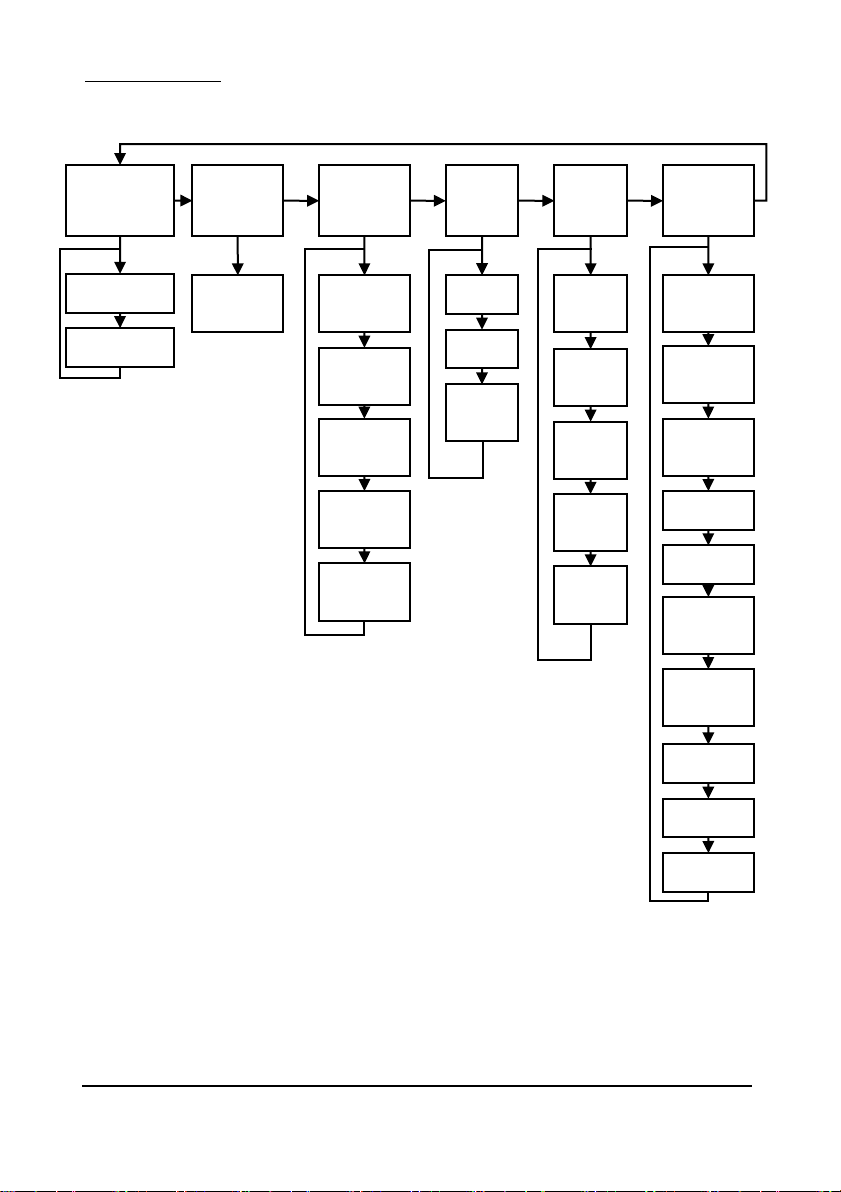
Page 56
System Menu
Passcode
Backup
System
Info
Date
&
Time
LED
Colour
Daylight
Saving
P921
Enable Code
P925
Parameter
Backup
P926
Software
Revision
P931
Date
P935
Off
Colour
P970
DST
Enable
P922
Passcode
P927
Hardware
Revision
P928
Serial
Number
P929
Site
Ident.
P930
Factory
Default
P931
Time
P932
Date
Format
P936
Alarm
Colour
P937
Pump
Colour
P938
Control
Colour
P939
Misc.
Colour
P971
DST
Difference
P972
DST
Start Time
P973
Start Day
P974
Start Week
P975
Start
Month
P976
DST
End Time
P977
End Day
P978
End Week
P979
End Month
Page 65
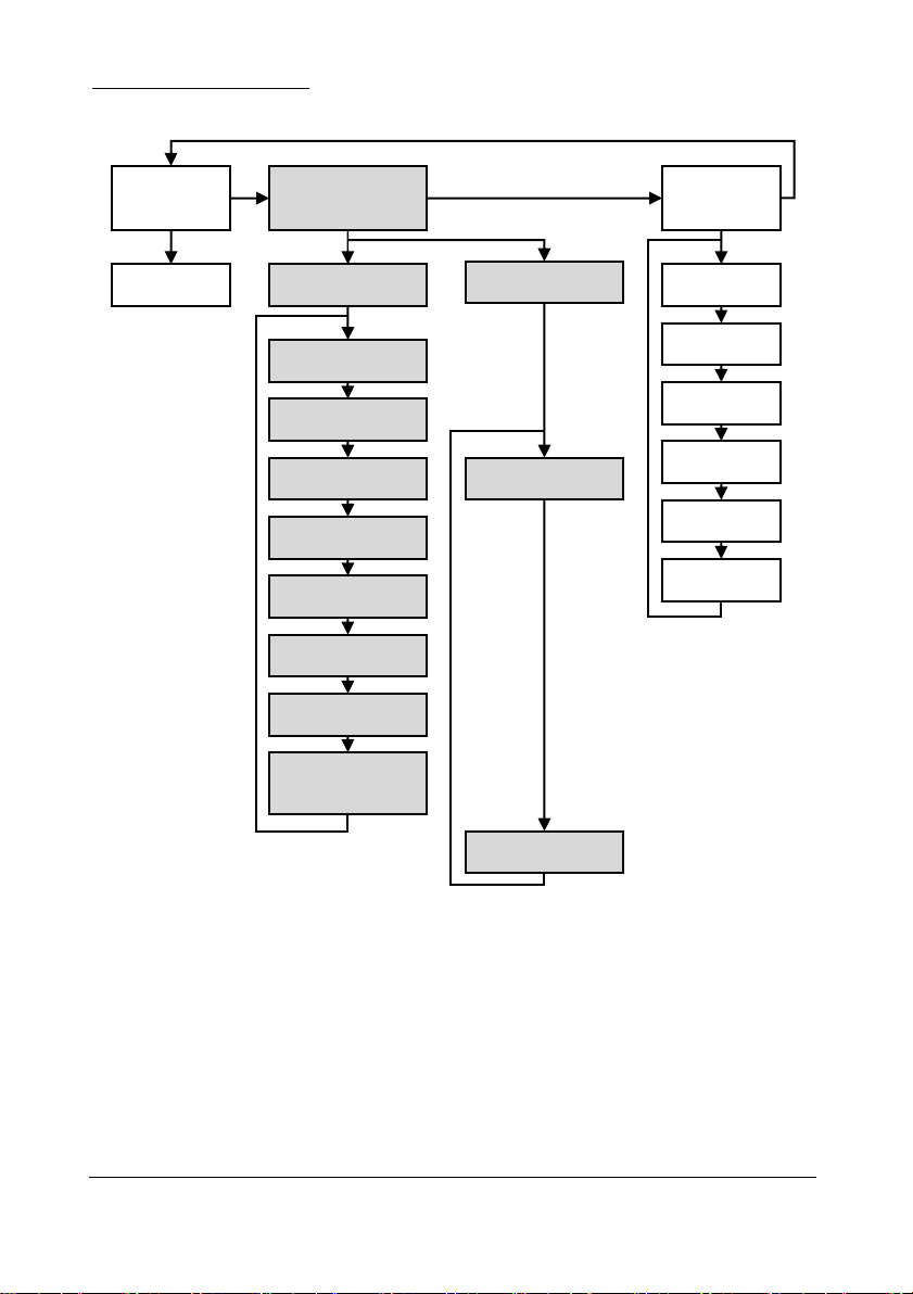
Page 57
Device Comm Menu
RS232
Set Up
RS485 Set Up
(Optional)
Remote
Alarm
If Comms. Type
MODBUS
If Comms. Type
PROFIBUS
P061
Comms Baud
P130
Device Mode
P131
Protocol
P132
Device Address
P133
Device Baud
P134
Parity
P135
Stop Bit
P136
Data Format
P137
Delay
(milliseconds)
P132
Device Address
P143
Address Lock
P144
Call Type
P145
Tel. No. 1
P146
Tel. No. 2
P147
Tel. No. 3
P148
Timed Out
P149
Retry No.
Page 66
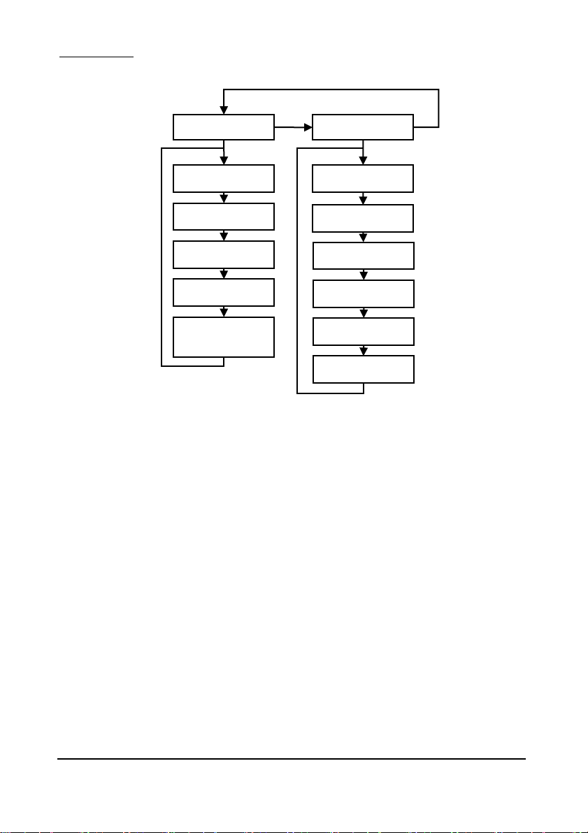
Page 58
Test Menu
Simulation
Hardware
P980
Simulate
P981
Increment
P982
Rate
P983
Start Level
P984
Incremental
Change
P990
Self Test
P991
Hardware Test
P992
mA Out Test
P994
Transducer Test
P995
Keys Test
P996
Relay Test
Page 67
Page 59
Parameter Listing
This section describes all of the parameters. Any parameter can be reset to its
default, by pressing the hot key, whilst in program mode.
Application Parameters
Operation
P100 Mode of Operation
This parameter sets the mode of operation, when in run mode, and can be set
to one of the following:
Option
Description
1= Distance (Default)
Display shows the distance from the transducer
face to the surface.
2= Level
Display shows how full the vessel is.
3= Space
Display shows how empty a vessel is.
P101 Xducer (Transducer)
This parameter should be set to the transducer being used with the unit, and
can be set to one of the following:
Option
Description
0=Auxiliary
Use the mA input device.
1 = dB3
Transducer is a dB3. Range 0.125 to 3.00 metres
2 = dB6 (Default)
Transducer is a dB6. Range 0.3 to 6.00 metres
3= dB10
Transducer is a dB10. Range 0.3 to 10.00 metres
4= dB15
Transducer is a dB15. Range 0.5 to 15.00 metres
5= dB25
Transducer is a dB25. Range 0.6 to 25.00 metres
6 = dB40
Transducer is a dB40. Range 1.2 to 40.00 metres
7 = dBS6
Transducer is a dBS6. Range 0.2 to 6.00 metres
8 = dBMach3
Transducer is a dBMach3 Range 0.0 to 2.425 mtrs.
10 = dB50
Transducer is a dB50. Range 2.0 to 50.00 metres
*11 = dBR16
Transducer is a mmWave radar. Range 0.077 to 16 metres
*12 = dBR8
Transducer is a mmWave radar. Range 0.077 to 8 metres
Important Information
* Please consult your local Pulsar distributor for the versions of firmware
that the mmWAVE Radars are available in.
Page 68

Page 60
P102 Material
This parameter should be set to the type of material being monitored.
Option
Description
1 = Liquid (Default)
Use for liquids and flat solid materials
2 = Solid
Solid material that is heaped or at an angle
3 = Closed Tank
Used where material is contained in a closed
tank.
Dimensions
P104 Measurement Units
This parameter sets the units you want to use for programming and display
Option
Description
1 = metres (Default)
All units of measure are METRES
2 = cm
All units of measure are CENTIMETRES
3 = mm
All units of measure are MILLIMETRES
4 = feet
All units of measure are FEET
5 = inches
All units of measure are INCHES
P105 Empty Level
This parameter is to be set to the maximum distance from the face of the
transducer to the empty point, in P104 Measurement Units. Note this value
affects span as well, (see important information below), so should be set
before span.
Important Information
When using the dB Mach 3 the empty distance is measured from the end
of the horn to the empty point in P104 Measurement Units.
Page 69

Page 61
Important Information
When changing the Empty Distance (P105) you can also recalculate the
values for the Span so that it equals the empty distance (P105) minus Near
Blanking (P107) and the Relay Setpoints, so that they remain at the same
percentage values of the empty distance as they were before you changed
the empty distance (P105). You will be asked the question “Recalculate
Span?” if you choose yes (enter 1), then the span will be recalculated. Any
other answer will leave the span at its original value. You will then be asked
if you want to “Recalculate Setpoints?”, if you choose yes (enter 1), then all
Relay Setpoints will be recalculated as a percentage of the new empty
distance. Any other answer will leave the setpoints at their original values.
P106 Span
This parameter should be set to the maximum distance from the Empty Level
(P105) to the maximum material level. It is automatically set to be equal to
the Empty Level (P105) less the Near Blanking distance (P107), when you
set the empty level.
P107 Near Blanking Distance
This parameter sets the distance from the face of the transducer that is not
measurable and is pre-set to the minimum value dependant on the Xducer
(P101) selected. It should not be set to less than this figure, but can be
increased, typically to ignore close in obstructions.
Transducer
Near Blanking Distance
P101 = dBMach3 Transducer
Default Blanking Distance = 0.000m
P101 = dB3 Transducer
Default Blanking Distance = 0.125m
P101 = dB6 Transducer
Default Blanking Distance = 0.300m
P101 = dB10 Transducer
Default Blanking Distance = 0.300m
P101 = dB15 Transducer
Default Blanking Distance = 0.500m
P101 = dB25 Transducer
Default Blanking Distance = 0.600m
P101 = dB40 Transducer
Default Blanking Distance = 1.200m
P101 = dBS6 Transducer
Default Blanking Distance = 0.200m
P101 = dB50 Transducer
Default Blanking Distance = 2.000m
P101 = dBR16 Radar
Default Blanking Distance = *0.077m
P101 = dBR8 Radar
Default Blanking Distance = *0.077m
*The signal emanates from the curved face of the Radar, but for the purposes
of measurement it is taken from the drip shield.
Page 70

Page 62
P108 Far Blanking Distance
This is the distance (as a percentage of empty level P105) beyond the empty
point that the unit will be able to measure, and by default is pre-set to 20%
of the empty level.
If the surface being monitored can extend beyond the Empty Level (P105)
then the far blanking distance can be increased to a maximum of 100% of
empty level.
This parameter is always entered as a % of empty level.
Page 71

Page 63
Relay Parameters
All relay related parameters are prefixed with a 2**.
The second digit of the three-figure parameter number denotes the relay
number as follows:
21* parameters for Relay 1 22* parameters for Relay 2
23* parameters for Relay 3 24* parameters for Relay 4
25* parameters for Relay 5 26* parameters for Relay 6
27* parameters for Relay 7 28* parameters for Relay 8
29* parameters for Relay 9 57* parameters for Relay 10
The third digit is parameter specific and is the same for each relay resulting
in the following parameter numbers for each relay.
Relay 1 210 to 219
Relay 2 220 to 229
Relay 3 230 to 239
Relay 4 240 to 249
Relay 5 250 to 259
Relay 6 260 to 269
Relay 7 270 to 279
Relay 8 280 to 289
Relay 9 290 to 299
Relay 10 570 to 579
Page 72

Page 64
P210, P220, P230, P240, P250, P260, P270, P280, P290, P570
Relay Type
This parameter defines what type each relay should be, see the table below
for available options.
Option
Description
0= Not In Use (Default)
Relay not programmed, and LED will always
be off.
1= Alarm
Relay is programmed as an alarm relay,
which will de-energise to switch the alarm
ON, and energise to switch the alarm OFF.
This will ensure an alarm is raised if the
power fails to the unit.
2= Pump
Relay is programmed as a pump relay, which
will energise to switch the pump ON, and
de-energise to switch the pump OFF.
3= Control
Relay is programmed as a control relay,
which will energise to switch ON, and deenergise to switch OFF.
4= Miscellaneous
Relay is programmed as a miscellaneous
relay, which will energise to switch ON, and
de-energise to switch OFF.
5= Pump by time
Relay is programmed as a pump relay, which
will energise at its ON level setpoint, and deenergise at its OFF level setpoint or after a
predetermined time period, whichever
occurs first.
Page 73

Page 65
Alarms
P210, 220, 230, 240, 250, 260, 270, 280, 290, 570 =1 (Alarm)
The second parameter for each relay will determine the function of the
alarm.
P211, P221, P231, P241, P251, P261, P271, P281, P291, P571
Relay Function
This parameter defines what function the alarm will respond to as follows.
Option
Description
0= Off (Default)
Relay will not operate.
1= Level
Alarm is based on the level in the vessel, and the type
of level alarm (P212, 222, 232, 242, 252, 262, 272,
282, 292, 572) and two setpoints must be set (P213,
223, 233, 243, 253, 263, 273, 283, 293, 573 & P214,
224, 234, 244, 254, 264, 274, 284, 294, 574). Setpoints
are entered in Display Units or % of span as referenced
to Empty Level *.
2= Rate of Change
Alarm is based on the rate of change of level in the
vessel, and the type of rate of change alarm (P212, 222,
232, 242, 252, 262, 272, 282, 292, 572) and two
setpoints must be set (P213, 223, 233, 243, 253, 263,
273, 283, 293, 573/P214, 224, 234, 243, 253, 263, 273,
283, 293, 573).Setpoints are entered in Display Units
per minute or % of span per minute and a negative
value should be entered for a Rate Alarm on a decreasing level, and a positive value for an increasing
level.
3= Temperature
Alarm is based on the temperature, and the type of
temperature alarm (P212, 222, 232, 242, 252, 262, 273,
283, 293, 573) and two setpoints must be set (P213,
223, 233, 243, 253, 263,273, 283, 293, 573 & P214,
224, 234, 244, 254, 264, 274, 284, 294, 574). The
temperature used depends on the temperature source
(P852). Setpoints are entered in oC.
4= Loss of Echo
Alarm is raised if the Failsafe Timer (P809) expires.
No setpoints are required.
5= Loss of Clock
Alarm is raised if the real time clock fails. No setpoints
are required.
Page 74

Page 66
Option
Description
6= Pump Efficiency
When Pump Efficiency is enabled, Alarm is based on
the Efficiency of the pump which is allocated to the
Relay I.D. (P212, 222, 232, 242, 252, 262, 272, 282,
292, 572) and two setpoints must be set (P213, 223,
233, 243, 253, 263, 273, 283, 293 & P214, 224, 234,
244, 254, 264, 274, 284, 294, 574). Setpoints are
entered in %.
7 = Device Fail
Alarm is raised if a device, connected to the relay
assigned in Alarm ID (P212, 222, 232, 242, 252,
262, 272, 282, 292, 572), fails. E.g. pump is put out
of service. No setpoints are required.
8 = Device Alarm
Alarm is raised if a fail signal is detected on the
digital input as assigned in Alarm ID (P212, 222,
232, 242, 252, 262, 272, 282, 292, 572) No setpoints
are required.
9 = OVF Alarm
Alarm is raised to indicate a “High” level or a
potential “Overflow” condition and four setpoints
must be set, Overflow Level (P213, 223, 233, 243,
253, 263, 273, 283, 293, 573). Reset Level (P214,
224, 234, 254, 264, 274, 284, 294, 574). High
Alarm Level (P215, 225, 235, 245, 255, 265, 275,
285, 295, 575). All level Setpoints are entered in
Display Units or % of span as referenced to Empty
Level *.
Time to Overflow (P219, 229, 239, 249, 259, 269,
279, 289, 579). Setpoint entered in minutes.
10 = RMA Alarm
Alarm is based on the rate of change of level during
a pumping cycle, and on the type of RMA alarm
(P212, 222, 232, 242, 252, 262, 272, 282, 292, 572)
and 3 setpoints must be set. Alarm Setpoint (P213,
223, 233, 243, 253, 263, 273, 283, 293, 573) in rate
measurement units. Persistence Time (P214, 224,
234, 254, 264, 274, 284, 294, 574) in seconds.
Prime Head Level (P215, 225, 235, 245, 255, 265,
275, 285, 295, 575) in level display units, alarm will
not activate below this level.
13 = Loss of Comms
Alarm is raised if there is a comms failure. No
setpoints are required.
15 = Tariff Alarm
(Available from
firmware version
7.5.1)
Alarm is raised when the unit enters Tariff Guard
mode. Tariff Guard enable (P393) must be set to
‘1’ for this option to be selectable. No setpoints are
required
Page 75

Page 67
To set figures in % press the hot key to show and enter % figure
relative to empty level.
Note that the loss of echo and loss of clock will also be shown on the display
as “LOST ECHO” and “LOST CLOCK” respectively.
P212, P222, P232, P242, P252, P262, P272, P282, P292, P572
Relay Alarm ID
The third parameter for each alarm relay determines the ID for the relay
you wish to set.
When P211, 221, 231, 241, 251, 261, 271, 281, 291, 571 = 1 (Level) or 2
(Rate of Change) or 3 (Temperature)
This parameter defines which alarm type, or identification, the relay should
respond to, as follows.
Alarm ID
Description
Setpoints
1= General (Default)
Relay goes “ON” when
the value rises to the
ON setpoint and goes
“OFF” when the value
lowers to the OFF
setpoint.
P213, 223, 233, 243,
253, 263, 273, 283,
293, 573 is ON
Setpoint;
P214, 224, 234, 244,
254, 264, 274, 284,
294, 574 is OFF
Setpoint
2= High
Relay goes “ON” when
the value rises to the
ON setpoint and goes
“OFF” when the value
lowers to the OFF
setpoint.
ON>OFF
Relay Setpoints
P213, 223, 233, 243,
253, 263, 273, 283,
293, 573 and P214,
224, 234, 244, 254,
264, 274, 284, 294,
574
Setpoints can be set
in any order as the
unit ‘knows’ that
you are setting a
high-level alarm.
3= Hi-Hi
Same as 2 = High, but
different identifier.
Page 76

Page 68
Alarm ID
Description
Setpoints
4= Low
Relay goes “ON” when
the value lowers to the
ON setpoint and goes
“OFF” when the value
rises to the OFF
setpoint.
ON<OFF
Relay Setpoints
P213, 223, 233,243,
253, 263, 273, 283,
293, 573 and P214,
224, 234, 244, 254,
264, 274, 284, 294,
574
Setpoints can be set
in any order as the
unit ‘knows’ that
you are setting a low
level alarm.
5= LoLo
Same as 4=Lo, but
different identifier.
6= In bounds
Relay goes “ON” if
value is inside the zone
between the two
setpoints.
Relay Setpoints,
P213, 223, 233, 243,
253, 263, 273, 283,
293, 573 and P214,
224, 234, 244, 254,
264, 274, 284, 294,
574
Setpoints can be set
in any order as the
unit ‘knows’ that
you are setting an in
bounds alarm.
7= Out of bounds
Relay goes “ON” if
value is outside the
zone between the two
setpoints.
Relay Setpoints,
P213, 223, 233, 243,
253, 263, 273, 283,
293, 573 and P214,
224, 234, 244, 254,
264, 274, 284, 294,
574
Setpoints can be set
in any order as the
unit ‘knows’ that
Page 77

Page 69
When P211, 221, 231, 241, 251, 261, 271, 281, 291, 571 = 4 (Loss of Echo),
5 (Loss of Clock) or 9 = OVF Alarm
This parameter has no function and will not be displayed.
When P211, 221, 231, 241, 251, 261, 271, 281, 291, 571 = 6 (Pump
Efficiency)
This parameter assigns the alarm to the appropriate pump relay as detailed
below.
Option
Description
0=Off (Default)
Relay will not operate.
1 = Relay 1
Alarm is assigned to pump on Relay 1
2 = Relay 2
Alarm is assigned to pump on Relay 2
3 = Relay 3
Alarm is assigned to pump on Relay 3
4 = Relay 4
Alarm is assigned to pump on Relay 4
5 = Relay 5
Alarm is assigned to pump on Relay 5
6 = Relay 6
Alarm is assigned to pump on Relay 6
7 = Relay 7
Alarm is assigned to pump on Relay 7
8 = Relay 8
Alarm is assigned to pump on Relay 8
9 = Relay 9
Alarm is assigned to pump on Relay 9
10 = Relay 10
Alarm is assigned to pump on Relay 10
11 = All
Alarm is assigned to all relays designated as pump
Page 78

Page 70
When P211, 221, 231, 241, 251, 261, 271, 281, 291, 571 = 7 (Device Fail)
This parameter defines which failed device relay, the alarm should respond
to, as follows.
Alarm ID
Description
Setpoints
1 = Fail Rel.1 (Default)
Relay goes “ON” when a device
failure is detected on relay 1.
None
2 = Fail Rel.2
Relay goes “ON” when a device
failure is detected on relay 2.
None
3 = Fail Rel.3
Relay goes “ON” when a device
failure is detected on relay 3.
None
4 = Fail Rel.4
Relay goes “ON” when a device
failure is detected on relay 4.
None
5 = Fail Rel.5
Relay goes “ON” when a device
failure is detected on relay 5.
None
6 = Fail Rel.6
Relay goes “ON” when a device
failure is detected on relay 6.
None
7 = Fail Rel.7
Relay goes “ON” when a device
failure is detected on relay 7.
None
8 = Fail Rel.8
Relay goes “ON” when a device
failure is detected on relay 8.
None
9 = Fail Rel.9
Relay goes “ON” when a device
failure is detected on relay 9.
None
10 = Fail Rel.10
Relay goes “ON” when a device
failure is detected on relay 10.
None
11 = Any 1 Fail
Relay goes “ON” when a device
failure is detected on any 1
relay.
None
12 = Any 2 Fail
Relay goes “ON” when 2
device failures are detected on
any 2 relays.
None
Page 79

Page 71
When P211, 221, 231, 241, 251, 261, 271, 281, 291, 571 = 8 (Device Alarm)
This parameter defines which digital input, the alarm should respond to, as
follows.
Alarm ID
Description
Setpoints
1 = Fail Inp.1 (Default)
Relay goes “ON” when a
fail signal is detected on
digital input 1.
None
2 = Fail Inp.2
Relay goes “ON” when a
fail signal is detected on
digital input 2.
None
3 = Fail Inp.3
Relay goes “ON” when a
fail signal is detected on
digital input 3.
None
4 = Fail Inp.4
Relay goes “ON” when a
fail signal is detected on
digital input 4.
None
5 = Fail Inp.5
Relay goes “ON” when a
fail signal is detected on
digital input 5.
None
6 = Fail Inp.6
Relay goes “ON” when a
fail signal is detected on
digital input 6.
None
7 = Fail Inp.7
Relay goes “ON” when a
fail signal is detected on
digital input 7.
None
Page 80

Page 72
When P211, 221, 231, 241, 251, 261, 271, 281, 291, 571 = 10 (RMA Alarm)
This parameter defines which alarm type, or identification, the relay should
respond to, as follows.
Alarm ID
Description
Setpoints
1 = Blockage
(Default)
Relay goes “ON” when the
pumping rate is lower than
the Alarm setpoint for
longer than the
Persistence Time
provided the level is above
the Prime Head and goes
“OFF” when the pumping
rate rises above the Alarm
setpoint for longer than the
Persistence Time.
P213, 223, 233, 243,
253, 263, 273, 283,
293, 573 is Alarm
Setpoint; P214, 224,
234, 244, 254, 264,
274, 284, 294, 574 is
Persistence Time;
P215, 225, 235, 245,
255, 265, 275, 285,
295, 575 is Prime
Head.
2 = Burst
Relay goes “ON” when the
pumping rate is above than
the Alarm setpoint for
longer than the
Persistence Time
provided the level is above
the Prime Head and goes
“OFF” when the pumping
rate lowers below the
Alarm setpoint for longer
than the Persistence Time.
P213, 223, 233, 243,
253, 263, 273, 283,
293, 573 is Alarm
Setpoint; P214, 224,
234, 244, 254, 264,
274, 284, 294, 574 is
Persistence Time;
P215, 225, 235, 245,
255, 265, 275, 285,
295, 575 is Prime
Head.
3 = NRV
Relay goes “ON” when a
pumping rate above the
Alarm setpoint is seen on
a FlowPulse that is
allocated to either “Pump
n” or “All” for longer than
the Persistence Time
provided the level is above
the Prime Head and goes
“OFF” when the pumping
rate lowers below the
Alarm setpoint for longer
than the Persistence Time.
P213, 223, 233, 243,
253, 263, 273, 283,
293, 573 is Alarm
Setpoint; P214, 224,
234, 244, 254, 264,
274, 284, 294, 574 is
Persistence Time;
P215, 225, 235, 245,
255, 265, 275, 285,
295, 575 is Prime
Head.
Page 81

Page 73
4 = Storm
Relay goes “ON” when the
pumping rate is above than
the Alarm setpoint for
longer than the
Persistence Time
provided the level is above
the Prime Head and goes
“OFF” when the pumping
rate lowers below the
Alarm setpoint for longer
than the Persistence Time.
P213, 223, 233, 243,
253, 263, 273, 283,
293, 573 is Alarm
Setpoint; P214, 224,
234, 244, 254, 264,
274, 284, 294, 574 is
Persistence Time;
P215, 225, 235, 245,
255, 265, 275, 285,
295, 575 is Prime
Head.
Page 82

Page 74
The fourth parameter and the fifth parameter for each relay set the Alarm
“ON” and “OFF” points. For a high alarm, the “ON” is set higher than
“OFF”. For low alarm, then “ON” is set lower than “OFF”. See the
appropriate alarm ID, table (P212, 222, 232, 242, 252, 262, 272, 282 292
572) for further information.
When P211, 221, 231, 241, 251, 261, 271, 281, 291, 571 = 1 (Level), 2
(Rate of Change), 3 (Temp.) or 6 (Efficiency)
P213, P223, P233, P243, P253, P263, P273, P283, P293, P73
Relay Setpoint 1
Determines the “ON” or “OFF” point for the alarm according to the ID selected.
P214, P224, P234, P244, P254, P264, P274, P284, P294, P574
Relay Setpoint 2
Determines the “ON” or “OFF” point for the alarm according to the ID selected.
Important Information
Setpoints are entered in values according to the function selected.
Level - entered in Display Units or % of span as referenced to Empty
Level.
Rate of Change - entered in Display Units per minute or % of span per
minute. For an alarm on an increasing level enter setpoints as a positive
value, for an alarm on a decreasing level enter setpoints as a negative
value.
Temperature - entered in ºC.
Efficiency – entered in % value of efficiency.
See the appropriate alarm function, table (P211, 221, 231, 241, 251,
261,271, 281, 291, 571) for further information.
* To set figures in % press the hot key to show and enter % figure
relative to empty level.
Page 83

Page 75
When P211, 221, 231, 241, 251, 261, 271, 281, 291, 571 = 4 (Loss of
Echo), 5 (Loss of Clock), 7 (Device Fail) or 8 (Device Alarm)
These parameters have no function and will not be displayed.
When P211, 221, 231, 241, 251, 261, 271, 281, 291, 571 = 9 (OVF Alarm)
P213, P223, P233, P243, P253, P263, P273, P283, P294, P573
Relay Setpoint 1
This parameter determines the “Overflow Level”, this is the level at which an overflow would occur and is the level that the unit will calculate the time to overflow to.
P214, P224, P234, P244, P254, P264, P274, P284, P294, P574
Relay Setpoint 2
This parameter determines the “Reset Level”, this level determines the point the
level has to be below (of fall below) before an activated alarm can be considered
to be deactivated, provided the time to overflow does not exceed the “Time to
Overflow” (P219, 229, 238, 249, 259, 269, 279, 289, 299, 579) and the level is
below the “Reset Level”, the alarm will turn “OFF”.
P215, P225, P235, P245, P255, P265, P275, P285, P295, P575
Relay Setpoint 3
This parameter determines the level at which the “High Alarm” will be activated
and should be set below or at the same level as the “Overflow Level” (P213, 223,
233, 243, 253, 263, 273, 283, 293, 573).
Relay setpoints 1, 2 and 3 are entered in values of Measurement Units (P104)
P219, P229, P239, P249, P259, P269, P279, P289, P299, P579
OVF Time
This parameter determines the time, prior to a potential overflow occurrence, at which the alarm will activate if it is calculated that an overspill is likely to occur.
Page 84

Page 76
When P211, 221, 231, 241, 251, 261, 271, 281, 291, 571 =10 (RMA Alarm)
P213, P223, P233, P243, P253, P263, P273, P283, P294, P573
Relay Alarm Setpoint
This parameter determines the RMA alarm ON/OFF point, this is the rate of
change during pumping at which a potential burst or blockage condition may
occur (depending on Relay Alarm ID). Units are in rate measurement units and
are dependent on P116 Rate Method.
P214, P224, P234, P244, P254, P264, P274, P284, P294, P574
Relay Setpoint 2
This parameter determines the “Persistence Time”. This is the amount of time
the rate has to persist above/below the Alarm Setpoint (P213, 223, 233, 243,
253, 263, 273, 283, 293, 573) before the alarm will change state. It is used to
prevent relay “chatter” if the rate is near the alarm setpoint. Units are in Seconds.
P215, P225, P235, P245, P255, P265, P275, P285, P295, P575
Relay Setpoint 3
This parameter determines the “Prime Head Level”. The RMA function will not
raise an alarm below this level but will allow an alarm to turn off. Units are in
Measurement Units (P104).
Page 85

Page 77
Pumps
When P210, 220, 230, 240, 250, 260, 270, 280, 290, 570 =2 (Pump)
When a relay is used for a pump function, then the second parameter
determines the pump duty that will be used to control the operating cycle of
the pump(s).
P211, P221, P231, P241, P251, P261, P271, P281, P291, P571
Relay Function,
This parameter defines which pump duty the relay should respond to as
follows.
Pump Duty
Description
0= Off (Default)
Relay is always de-energised.
1= Fixed duty assist
All pumps are used to assist each
other (run at the same time) and
each pump has its own setpoints.
(P213, 223, 233, 243, 253, 263,
273, 283, 293, 573 & P214, 224,
234, 244, 254, 264, 274, 284,
294, 574).
2= Fixed duty backup
If a pump fails to meet the
demand (due to malfunction,
intake blockage etc.), then it is
stopped and another pump shall
take over. Each pump has its own
setpoints. (P213, 223, 233, 243,
253, 263, 273, 283, 293, 573 &
P214, 224, 234, 244, 254, 264,
274, 284, 294, 574).
3= Alternate duty assist
All pumps are used to assist each
other (run at the same time) and
each pump has its own setpoints,
(P213, 223, 233, 243, 253, 263,
273, 283, 293, 573 & P214, 224,
234, 244, 254, 264, 274, 284,
294, 574). but each time all
pumps have stopped, then the
setpoints are sequentially rotated
between the pumps to ensure
equal pump use.
Page 86

Page 78
Pump Duty
Description
4= Alternate duty backup
If a pump fails to meet the
demand (due to malfunction,
intake blockage etc.), then it is
stopped and another pump shall
take over. Each pump has its own
setpoints, (P213, 223, 233, 243,
253, 263, 273, 283, 293, 573 &
P214, 224, 234, 244, 254, 264,
274, 284, 294, 574). but each time
all pumps have stopped, then the
setpoints are sequentially rotated
between the pumps to ensure
equal pump use.
5= Duty backup and assist
First pump comes on, if it cannot
cope, it goes off and next pump
comes on (duty backup). This
continues until the last pump
comes on and if it cannot cope the
first pump comes back on to
assist the last pump (duty assist)
if the level continues to rise all
other pumps will come on (assist)
in turn until the level decreases to
the pump off points. Each pump
has its own setpoints, (P213, 223,
233, 243, 253, 263, 273, 283,
293, 573 & P214, 224, 234, 244,
254,264, 274, 284, 294, 574).
Page 87

Page 79
Pump Duty
Description
6= Service ratio duty assist
All pumps are used to assist each
other (run at the same time) and
each pump has its own setpoints
(P213, 223, 233, 243, 253, 263,
273, 283, 293, 573 & P214, 224,
234, 244, 254, 264, 274, 284, 294,
574). And a service ratio setting.
The third setpoint (P215, 225,
235, 245, 255, 265, 275, 285, 295,
575) is used to set the service
ratio. Each time a pump is
required to start then the pump
with the least running hours (with
respect to the service ratio) is
started (i.e. the setpoints are reassigned accordingly).
For example, if two pumps A and
B have the service ratio set to 2
and 1 respectively, then pump A
will operate for twice as many
hours as pump B.
7= Service ratio duty backup
If a pump fails to meet the
demand (due to malfunction,
intake blockage and so on), then
it is stopped and another pump
shall take over. Each time a pump
is required to start then the pump
with the least running hours (with
respect to the service ratio) is
started (i.e. the setpoints are reassigned accordingly). Each
pump has its own setpoints (P213,
223, 233, 243, 253, 263, 273,
283, 293, 573 & P214, 224, 234,
244, 254, 264, 274, 284, 294,
574). The third setpoint (P215,
225, 235, 245,255, 265, 275, 285,
295, 575) is used to set the
service ratio. For example, if two
pumps A and B have the service
ratio set to 2 and 1 respectively,
then pump A will operate for
twice as many hours as pump B.
Page 88

Page 80
Pump Duty
Description
8= First On First Off, alternate duty
assist
The first pump switched on is the
first pump to be switched off, etc.
regardless of the set points, so the
setpoints are dynamically
changed to enable this.
9 = Service Ratio Standby
When a service ratio duty is being
used, on all other pumps in use,
the standby pump can be started
on a ratio basis only, when it will
assume the setpoints of the next
pump to start. The third setpoint
(P215, 225, 235, 245,255, 265,
275, 285, 295, 575) is used to set
the service ratio.
10 = Two Pump Sets
There are four pumps. Two rotate
their start-up sequence with each
other. If the two pumps cannot
keep up, the level rises to the
setpoints of the other two pumps,
which take over and rotate their
sequence with each other.
Important Information
The pumps are started and stopped at the “ON” and “OFF” setpoints. To
pump down (reduce level) then set “ON” higher than “OFF”. To pump up
(increase level) then set “ON” lower than “OFF”.
The third parameter for each relay determines the pump group. You can
have two groups of pumps, and all similar duties within a group will operate
together.
P212, P222, P232, P242, P252, P262, P272, P282, P292, P572
Relay Pump Group
By default, all pump groups are set to 1, but if you want to have another
group, then set this parameter to 2, for each pump relay that should operate
together as part of a second group.
Page 89

Page 81
The fourth parameter and the fifth parameter for each relay set the pump
“ON” and “OFF” points, which are entered in Measurement units P104. For
pump down the “ON” is set higher than “OFF”. For pump up then “ON” is
set lower than “OFF”. See the appropriate pump duty, function table (P212,
222, 232, 242, 252, 262, 272, 282, 292, 572) for further information.
P213, P223, P233, P243, P253, P263, P273, P283, P293, P573
Relay Setpoint 1
This parameter will determine the “ON” point of the pump(s).
P214, P224, P234, P244, P254, P264, P274, P284, P294, P574
Relay Setpoint 2
This parameter will determine the “OFF” point for the pump(s).
Relay setpoints 1 and 2 are entered in values of Measurement Units (P104)
See the appropriate pump duty function, table (P211, 221, 231, 241, 251,
261, 271, 281, 291, 571), for further information.
The sixth parameter will determine the service ratio that will be used to
switch the pump, when pump duty selected is a Service Ratio duty.
P211, 221, 231, 241, 251, 261,271, 281, 291, 571 = 6, 7 or 9 (Service ratio)
P215, P225, P235, P245, P255, P265, P275, P285, P295, P575
Relay Setpoint 3
This parameter determines the Service Ratio in values of %. See the
appropriate pump duty function, table (P211, 221, 231, 241, 251, 261, 271,
281, 291, 571), for further information.
P219, P229, P239, P249, P259, P269, P279, P289, P299, P579
Relay Max.Rate
This parameter will allow a pump to be switched at a pre-determined Rate
of change of Level, irrespective of the “ON” level setpoint P213, 223, 233,
243, 253, 263, 273, 283, 293, 573. Once a pump relay has been switched
“ON” by the pre-determined Rate of Change, it will remain energised until
the level reaches the “OFF” level setpoint P214, 224, 234, 244, 254, 264,
274, 284, 294, 574.
Max. Rate is entered in Measurement Units (P104) per minute and can be
entered in positive (increasing level) or negative (decreasing level) values.
Page 90

Page 82
Control
When P210, 220, 230, 240, 250, 260, 270, 280, 290, 570 = 3 (Control)
When a relay is being set up as a control relay, the second parameter that
will be displayed in the menu determines its function.
P211, P221, P231, P241, P251, P261, P271, P281, P291, P571
Relay Function,
This function allows the relay to be assigned to specific control functions
(other than pumps and alarms) several of these functions work in relation to
time.
This can be used to activate devices based on elapsed time or running cycles,
such as a timed rake control to keep a ram lubricated if idle for long periods,
or flush valve operation.
Options
Description
0 = Off (Default)
Relay is always de-energised
1 = Time
Relay will energise “ON” after the Cycle
time that is set in Relay Setpoint 2 (P214,
224, 234, 244, 254, 264, 274, 284, 294, 574).
And turns “OFF”, de-energises, after the On
Time Period that is set in Relay Setpoint 1
(P213, 223, 233, 243, 253, 263, 273, 283,
293, 573)
2 = Storm
Relay will energise “ON” when storm
conditions are in effect and, de-energise
“OFF” when storm conditions cease. Two
setpoints are required, Upper Storm “ON”,
(P213, 223, 233, 243, 253, 263, 273, 283,
293, 573) and Lower Storm, “OFF” (P214,
224, 234, 244, 254, 264, 274, 284, 294, 574).
This allows the relay to be used to activate a
device as a result of high levels such as a
storm condition e.g. opening a gate valve to
divert storm overflow into a holding vessel.
Page 91

Page 83
Options
Description
3 = Aeration
Relay will energise “ON” after each Cycle
time as set in Relay Setpoint 2 (P214, 224,
234, 244, 254, 264, 274, 284, 294, 574). And
turns “OFF”, de-energises, after the set On
Time Period as set in Relay Setpoint 1
(P213, 223, 233, 243,253, 263, 273, 283, 293,
573). This can be used to activate a device
based upon elapsed time since All Pumps
have been “OFF”, such as the introduction of
fresh air to reduce gas concentration.
4 = Flush Valve
Relay will energise “ON” when Flush
condition is in effect and goes off when Flush
condition is cleared. A relay being used for
Flush Valve/Pump must be assigned to one of
the main pumps in use.
Flush relay Alarm ID (P212, 222, 232, 242,
252, 262, 272, 282, 292, 572) is used to enter
the relay number, to which the assigned
pump is connected.
Flush Valve/Pump relay requires three
setpoints. The first set point (P213, 223, 233,
243, 253, 263, 273, 283, 293, 573) determines
the Flush Interval, which is the number of
main pump cycles that should occur before
the Flush Valve/Pump operates. The second
setpoint (P214, 224, 234, 244, 254, 264, 274,
284, 294, 574), sets the number of Flush
cycles the Flush Valve/Pump will operate for.
This means that the Flush Valve will be
operated for a number of main pump starts
(Flush Cycles) after which the Flush Valve
activity will cease until the Flush Interval
comes around again. Setpoint three of the
Flush Valve/Pump relay sets the Flush
Duration, (P215, 225, 235, 245, 255, 265,
275, 285, 295, 575) this is the duration for
Flush Cycle, in seconds.
Page 92

Page 84
Options
Description
5=Step Time
Step Time Control allows relays to be used to
control a device, such as a motorised valve or
gate, in order to maintain the level within two
predetermined points. Relays will energise
“ON” when Step Time condition is in effect
and de-energises “OFF” when Step Time
goes off. One relay will be required to control
an increase in level, (‘open’ the device) and a
second relay is required to control a decrease
in level, (‘close’ the device). Alarm ID
(P212, 222, 232, 242, 252, 262, 272, 282,
292, 572) is used to assign the relay to control
either the open or close condition. Step Time
Control relay requires three setpoints. The
first set point (P213, 223, 233, 243, 253, 263,
273, 283, 293, 573) determines the level, at
which the relay is to be activated, (N.B. level
setpoint for open relay, increase the level,
must be lower than the setpoint for the close
relay, decrease the level). The relay will
energise “ON” after the Limit time that is set
in Relay Setpoint 3 (P215, 225, 235, 245,
255, 265, 275, 285, 295, 575). And turns
“OFF”, de-energises, after the Drive Period
that is set in Relay Setpoint 2 (P214, 224,
234, 244, 254, 264, 274, 284, 294, 574).
6 = Differential Control
Relay will energise “ON” when a differential
condition is in effect and, de-energise “OFF”
when the differential conditions cease. Two
setpoints are required, Differential control
“ON”, (P213, 223, 233, 243, 253, 263, 273,
283, 293, 573) and Differential control,
“OFF” (P214, 224, 234, 244, 254, 264, 274,
284, 294, 574).
This allows the relay to be used to activate a
device as a result of a differential level,
between two points e.g. operate a rake on a
Page 93

Page 85
Options
Description
7 = Pump Reset
Relay will energise “ON” for the period of
the Reset Pulse (P309) after expiry of the
Reset Interval (P308), provided the level is
above the Prime Level (P349), to reset the
designated pump that has tripped. Alarm ID
(P212, 222, 232, 242, 252, 262, 272, 282,
292, 572) is used to enter the relay number,
to which the designated pump is connected.
The third parameter for each relay determines the assignment or condition
of the relay, where required.
P212, P222, P232, P242, P252, P262, P272, P282, P292, P572
Relay Alarm ID/Pump Group,
P211, 221, 231, 241, 251, 261, 271, 281, 291, 571 = 1, 2, 3 or 6
This parameter has no function and will not be displayed.
P211, 221, 231, 241, 251, 261, 271, 281, 291, 571 = 4 (Flush Valve)
If the relay is selected for Flush Valve/Pump, then this parameter is used to
determine to which pump the Flush function is assigned. Enter the relay
number to which the assigned pump is connected.
P211, 221, 231, 241, 251, 261, 271,281,291,571 = 5 (Step Time)
If the relay is selected for Step Time, then this parameter is used to assign the
relay to the 0 = Open condition (increase level) or 1 = Close condition
(decrease level).
P211, 221, 231, 241, 251, 261, 271, 281, 291, 571 = 7 (Pump Reset)
If the relay is selected for Pump Reset, then this parameter is used to
determine to which pump the Pump Reset function is assigned. Enter the
relay number to which the assigned pump is connected.
Page 94

Page 86
The fourth parameter, fifth parameter and sixth parameter are set to
determine the switch points, “ON” and “OFF” for the relay and where
required the order of start. See control function, table (P211, 221, 231, 241,
251, 261, 271, 281, 291, 571) for further information.
P213, P223, P233, P243, P253, P263, P273, P283, P293, P573
Relay Setpoint 1
P211, 221, 231, 241, 251, 261, 271, 281, 291, 571 =1 (Time)
This parameter determines the “Time Period ” that the relay will remain “ON”.
Relay Setpoints are entered in Minutes.
See the appropriate relay Function tables (P211, 221, 231, 241, 251, 261, 271,
281, 291, 571) for further information. P211, 221, 231, 241, 251, 261, 271, 281, 291, 571 = 2 (Storm)
Relay Setpoint 1 is entered in values of Measurement Units (P104)
See the appropriate relay function tables (P211, 221, 231, 241, 251, 261, 271, 281,
291, 571) for further information. P211, 221, 231, 241, 251, 261, 271, 281, 291, 571 = 3 (Aeration)
Relay Setpoint 1 is entered in Minutes to set Cycle Time
See the appropriate relay Function tables (P211, 221, 231, 241, 251, 261, 271,
281, 291, 571) for further information. P211, 221, 231, 241, 251, 261, 271, 281, 291, 571 = 4 (Flush Valve)
Relay Setpoint 1 is entered in Pump cycles to set Flush Interval.
See the appropriate relay Function tables (P211, 221, 231, 241, 251, 261, 271,
281, 291, 571) for further information. P211, 221, 231, 241, 251, 261, 271, 281, 291, 571 =5 (Step Time)
Relay Setpoint 1 is entered in values of Measurement Units (P104)
See the appropriate relay function tables (P211, 221, 231, 241, 251, 261, 271, 281,
291, 571) for further information. P211, 221, 231, 241, 251, 261, 271, 281, 291, 571 =6 (Differential)
Relay Setpoint 1 is entered in values of Measurement Units (P104)
See the appropriate relay function tables (P211, 221, 231, 241, 251, 261, 271, 281,
291, 571) for further information.
Page 95

Page 87
P211, 221, 231, 241, 251, 261, 271, 281, 291, 571 = 7 (Pump Reset)
This parameter has no function and will not be displayed.
P214, P224, P234, P244, P254, P264, P274, P284, P294, P574
Relay Setpoint 2
P211, 221, 231, 241, 251, 261, 271, 281, 291, 571 = 1 (Time)
This parameter determines the “Cycle Time ” for the operation of the relay.
See the appropriate relay Function tables (P211, 221, 231, 241, 251, 261, 271,
281, 291, 571) for further information. P211, 221, 231, 241, 251, 261, 271, 281, 291, 571 = 2 (Storm)
Relay Setpoints are entered in values of Measurement Units (P104)
See the appropriate relay Function tables (P211, 221, 231, 241, 251, 261, 271,
281, 291, 571) for further information. P211, 221, 231, 241, 251, 261, 271, 281, 291, 571 = 3 (Aeration)
Relay Setpoints are entered in Minutes to set Time Period that the relay will remain ON
See the appropriate relay Function tables (P211, 221, 231, 241, 251, 261, 271,
281, 291, 571) for further information. P211, 221, 231, 241, 251, 261, 271, 281, 291, 571 = 4 (Flush Valve)
Relay Setpoints are entered in cycles to set the number of Flush cycles.
See the appropriate relay Function tables (P211, 221, 231, 241, 251, 261, 271,
281, 291, 571) for further information. P211, 221, 231, 241, 251, 261, 271, 281, 291, 571 = 5 (Step Time)
Relay Setpoints are entered in Seconds to set Drive Period, the time that the relay will remain ON
See the appropriate relay Function tables (P211, 221, 231, 241, 251, 261, 271,
281, 291, 571) for further information. P211, 221, 231, 241, 251, 261, 271, 281, 291, 571 =6 (Differential)
Relay Setpoints are entered in values of Measurement Units (P104)
See the appropriate relay Function tables (P211, 221, 231, 241, 251, 261, 271,
281, 291, 571) for further information.
Page 96

Page 88
P211, 221, 231, 241, 251, 261, 271, 281, 291, 571 = 7 (Pump Reset)
This parameter has no function and will not be displayed.
P215, P225, P235, P245, P255, P265, P275, P285, P295, P575
Relay Setpoint 3
P211, 221, 231, 241, 251, 261, 271, 281, 291, 571 = 1, 2, 3, 6 or 7
This parameter has no function and will not be displayed.
P211, 221, 231, 241, 251, 261, 271, 281, 291, 571 = 4 (Flush Valve)
Enter desired Flush duration in seconds.
See the appropriate relay Function tables (P211, 221, 231, 241, 251, 261,
271, 281, 291, 571) for further information.
P211, 221, 231, 241, 251, 261, 271, 281, 291, 571 = 5 (Step Time)
This parameter is used to determine the Limit Time between each Drive Period. Relay Setpoints are entered in Minutes, during which time the relay will remain OFF.
See the appropriate relay Function tables (P211, 221, 231, 241, 251, 261,
271, 281, 291, 571) for further information.
Page 97

Page 89
Miscellaneous
When P210, 220, 230, 240, 250, 260, 270, 280, 290, 570 = 4 (Miscellan.)
When a relay is set to be miscellaneous relay, the second parameter
determines its function.
P211, P221, P231, P241, P251, P261, P271, P281, P291, P571
Relay Function,
This function allows the relay to work in relation to a clock and will be set to
activate in relation to Real Time or to provide a pulsed output in relation to a
predetermined count from the totaliser, the choices being as follows:
Options
Description
0 = Off (Default)
Relay Off de-energised
1 = Clock
Relay will energise ON at a specified time
each day as set in Relay Setpoint 1 (P213,
223, 233, 243, 253, 263, 273, 283, 293,
573). And turns OFF, de-energises, after
the specified On Time period as set in Relay
Setpoint 2 (P214, 224, 234, 244, 254, 264,
274, 284, 294, 574)
2 = Totaliser
Relay will energise ON momentarily each
time the specified flow has passed as set in
Relay setpoint 1 (P213, 223, 233, 243, 253,
263, 273, 283, 293, 573), this parameter sets
the multiplication factor which will be
applied to the on board totaliser (P820) to
determine the switch point of the relay. E.g.
if the totaliser is set to totalise in cubic
metres and the relay is required to provide a
closure every 10,000 litres Relay setpoint 1
would be set to 10. Relay setpoint 2 (P214,
224, 234, 244, 254, 264, 274, 284, 294, 574)
can be used to select the time the relay will
remain closed in seconds.
Page 98

Page 90
Important Information
When using a Relay to control a device at a specified time of day ensure that
the Time P932 is set correctly. And if required, enable Daylight Saving for
the appropriate time difference P970 – P979.
The third parameter has no function when miscellaneous relay is chosen
and will not be displayed.
The fourth parameter, and fifth parameter, are set to determine the switch
points, “ON” and “OFF” for the relay. See miscellaneous function table
(P211, 221, 231, 241, 251, 261, 271, 281, 291, 571) for further information.
P211, 221, 231, 241, 251, 261, 271, 281, 291, 571 = 1 (Clock)
P213, P223, P233, P243, P253, P263, P273, P283, P293, P573
Relay Setpoint 1
Relay Setpoints are entered in Hours & Minutes (HH:MM) to set Time at which relay will energise. Default = 00:00 (HH:MM)
P214, P224, P234, P244, P254, P264, P274, P284, P294, P574
Relay Setpoint 2
Relay Setpoints are entered in Minutes to set Time Period that the relay will remain ON. Default = 0.00 mins.
P211, 221, 231, 241, 251, 261, 271, 281, 291, 571 = 2 (Totaliser)
P213, P223, P233, P243, P253, P263, P273, P283, P293, P573
Relay Setpoint 1
Relay Setpoints are entered as a factor by which the on board totaliser (P820) should be multiplied by to provide a relay closure. Default = 0.00
P214, P224, P234, P244, P254, P264, P274, P284, P294, P574
Relay Setpoint 2
Relay Setpoints are entered in seconds to set the time period that the relay will remain ‘ON’. Default = 0.00 secs.
Page 99

Page 91
Pump by Time
When a relay is assigned to Pump by Time the pump will come on (energise)
at its normal “ON” level setpoint, and de-energise at its OFF level setpoint
or after a predetermined time period, whichever occurs first.
P210, 220, 230, 240, 250, 260, 270, 280, 290, 570 = 5 (Pump by Time)
When a relay is being used for a pump by time function, the second
parameter determines the pump duty that will be used to determine the
operating cycle.
P211, P221, P231, P241, P251, P261, P271, P281, P291, P571
Relay Function,
This parameter defines which pump duty the relay should respond to as
follows.
Pump Duty
Description
0= Off (Default)
Relay is always de-energised.
1= Fixed duty assist
All pumps are used to assist each other
(run at the same time) and each pump
has its own setpoints. (P213, 223, 233,
243, 253, 263, 273, 283, 293, 573 &
P214, 224, 234, 244, 254, 264, 274, 284,
294, 574).
2= Fixed duty backup
If a pump fails to meet the demand (due
to malfunction, intake blockage etc.),
then it is stopped and another pump shall
take over. Each pump has its own
setpoints. (P213, 223, 233, 243, 253,
263, 273, 283, 293, 573 & P214, 224,
234, 244, 254, 264, 274, 284, 294, 574).
3= Alternate duty assist
All pumps are used to assist each other
(run at the same time). Each pump has
its own setpoints, (P213, 223, 233, 243,
253, 263, 273, 283, 293, 573 & P214,
224, 234, 244, 254, 264, 274, 284, 294,
574) but each time all pumps have
stopped, the setpoints are sequentially
rotated between the pumps to ensure
equal pump use.
Page 100

Page 92
Pump Duty
Description
4= Alternate duty backup
If a pump fails to meet the demand (due
to malfunction, intake blockage etc.),
then it is stopped and another pump shall
take over. Each pump has its own
setpoints, (P213, 223, 233, 243, 253,
263, 273, 283, 293, 573 & P214, 224,
234, 244, 254, 264, 274, 284, 294, 574).
but each time all pumps have stopped,
then the setpoints are sequentially
rotated between the pumps to ensure
equal pump use.
5= Duty backup and assist
First pump comes on, if it cannot cope,
it goes off and next pump comes on
(duty backup). This continues until the
last pump comes on and if it cannot cope
the first pump comes back on to assist
the last pump (duty assist) if the level
continues to rise all other pumps will
come on (assist) in turn until the level
decreases to the pump off points. Each
pump has its own setpoints, (P213, 223,
233, 243, 253, 263, 273, 283, 293, 573
& P214, 224, 234, 244, 254, 264, 274,
284, 294, 574).
Important Information
The pumps are started and stopped at the “ON” and “OFF” setpoints. To
pump down (reduce level) then set “ON” higher than “OFF”. To pump up
(increase level) then set “ON” lower than “OFF”.
The third parameter for each relay determines the pump group. You can
have two groups of pumps, and all similar duties within that group will
operate together.
 Loading...