

Page 1
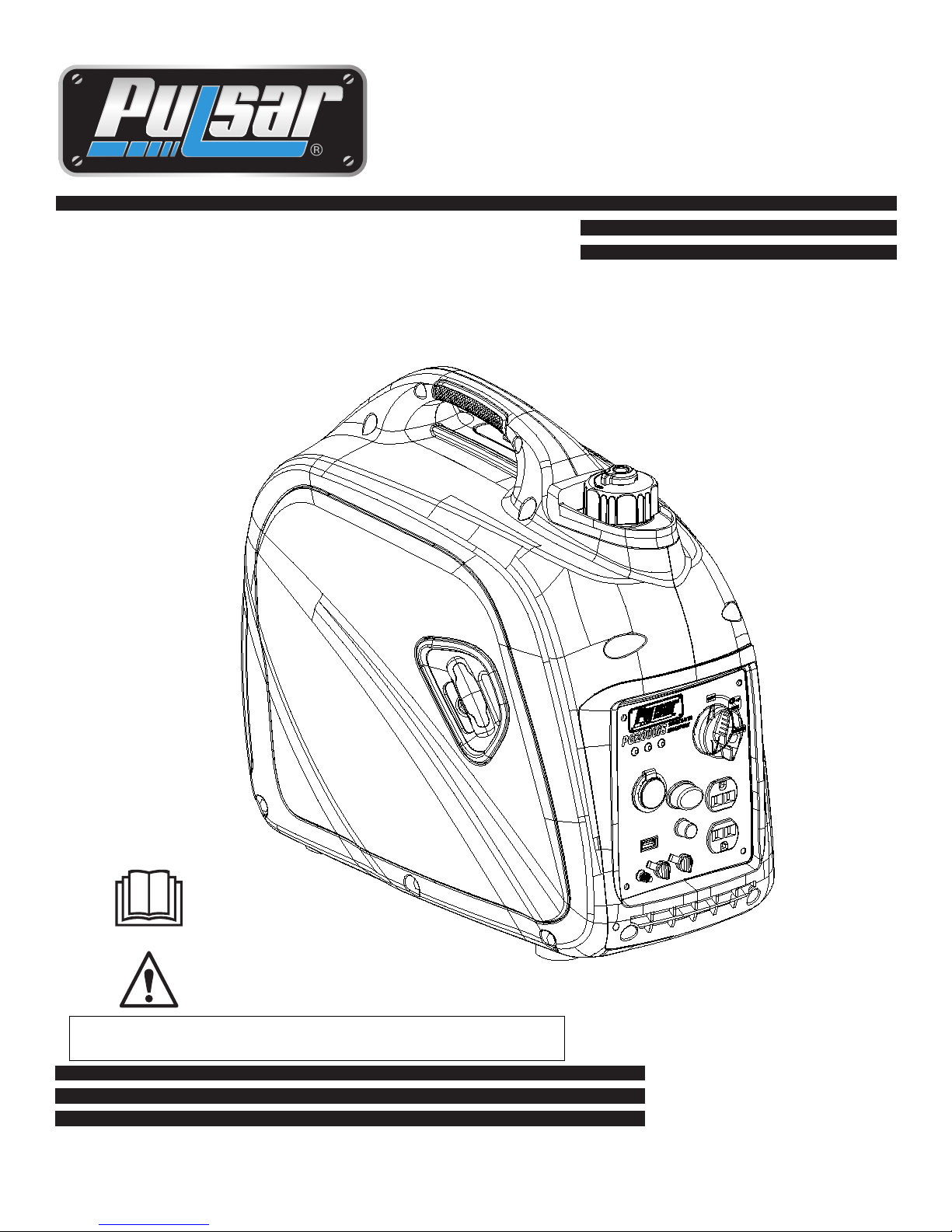
Inverter Gasoline
OPERATOR’S MANUAL
Model: PG2000iS
Warning: The Engine Exhaust from this product contains chemicals known to
the State of California to cause cancer, birth defects or other reproductive harm.
Page 2

TABLE OF CONTENTS
Introduction . .......................................................................................................................................................................... 3
Parts Ordering / Customer Service. . .......................................................................................................................... 3
Safety Rules . ......................................................................................................................................................................... 4
Safety Symbols ........................................................................................................................................................... 4
Safety Instructions . .................................................................................................................................................... 4
Features .................................................................................................................................................................................. 7
Control Panel Functions . ..................................................................................................................................................... 8
ON/OFF Start Switch and Choke. .............................................................................................................................. 8
................................................................................................................................................................ 8U SB Outlet
Indicator Lights. .......................................................................................................................................................... 8
DC Protector. ............................................................................................................................................................. 9
Engine “Economy” Control . . ..................................................................................................................................... 9
Parallel Outlets. ........................................................................................................................................................ 10
Fuel Cap Air Vent. .................................................................................................................................................... 10
Ground Terminal. ..................................................................................................................................................... 10
Assembly . . ............................................................................................................................................................................ 11
Connecting Generator to an Electrical System........................................................................................................ 11
Adding Fuel. .............................................................................................................................................................. 11
Adding / Checking Oil . ............................................................................................................................................ 12
Operation . ............................................................................................................................................................................ 13
Grounding the Generator . ........................................................................................................................................ 13
How to Start Engine. ................................................................................................................................................. 13
How to Stop Engine. .................................................................................................................................................. 14
Attaching Electronic Devices. .................................................................................................................................... 14
Charging a 12 Volt Battery. ....................................................................................................................................... 15
AC Parallel Operation. ............................................................................................................................................. 16
Don’t Overload Generator. ....................................................................................................................................... 17
Wattage Reference Guide. ........................................................................................................................................ 17
Maintenance . . ...................................................................................................................................................................... 18
Maintenance Schedule . . .......................................................................................................................................... 18
Checking Spark Plug . . .......................................................................................................................................... 19
Changing Oil . ........................................................................................................................................................... 20
How to Clean Air Filter. ............................................................................................................................................. 21
.....................................................................................................................
Checking Muffler and Spark Arrestor
How to Clean Fuel Filter . ....................................................................................................................................... 22
.
21
Transport& & Storage
Troubleshooting . ................................................................................................................................................................. 24
Specifictions.......................................................................................................................................................................... 25
Noise...................................................................................................................................................................................... 25
Warranty ............................................................................................................................................................................... 30
............................................................................................................................................................... 22
Page 3
INTRODUCTION
Thank you for purchasing this superior quality portable generator from PULSAR PRODUCTS INC. When operating and
maintaining this product as instructed in this manual, your generator will give you many years of reliable service.
This generator is an engine-driven, portable generator.It is designed to supply electrical power to operate tools, appliances,
camping equipment, lighting, or serve as a back up power source during power outages.
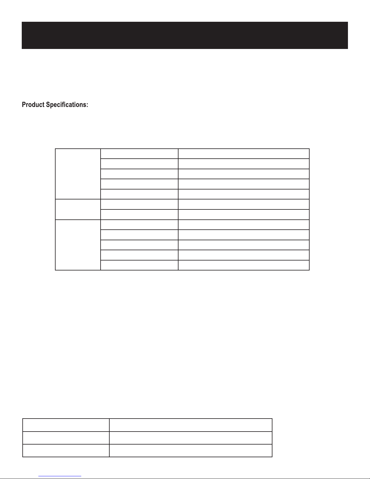
Rated AC Voltage
Rated Frequency
AC Output
DC Output
Engine
The emissions control system for this generator is compliant with all standards set by the Environmental Protection Agency.
AC Current
Rated Output 1600W
Maximum Output 2000W
USB Outlet
Cigarette Outlet
Displacement 80cc
Engine Type Single cylinder, 4 Stroke, OHV, Air Cooled
Engine Oil Type SAE 10W30
Engine Oil Capacity 350ml / 11.8oz
Fuel Tank Capacity 4.5L / 1.18Gal
120V
60Hz
13.3A
5V DC 1.5A
12V DC 8A
How to contact us:
You can contact us by Telephone: 1.866.591.8921, Email: [email protected], or write to us at:
Record the following information below for service or warranty assistance.
Date of Purchase:
Model Number:
Serial Number
PULSAR PRODUCTS.INC.
2051 S. Lynx Place
Ontario, California, U.S.A. 91761
Page 4
Safety Symbols
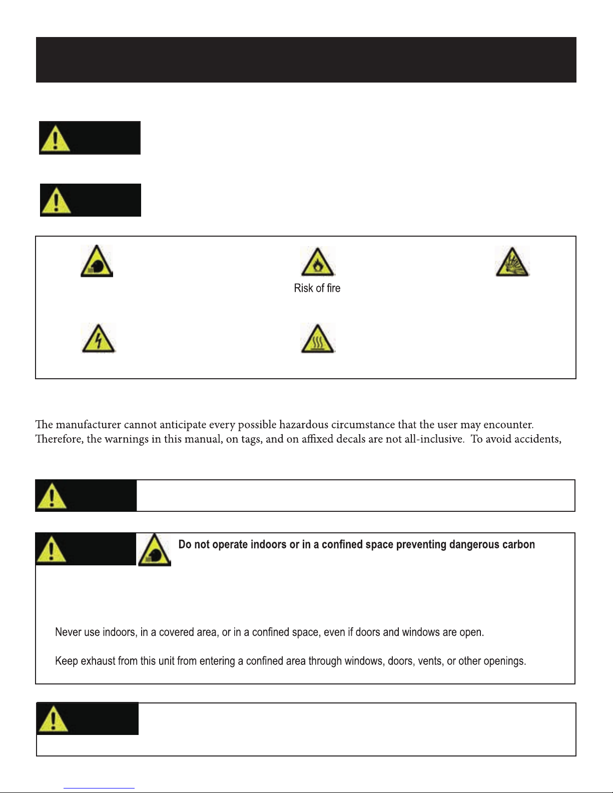
WARNING!
CAUTION!
SAFETY RULES
Indicates a potentially hazardous
situation which could result in
serious injury or death if not avoided.
Indicates a potentially hazardous
situation which could result in
damage to equipment or property.
Toxic Fumes
Risk of electric shock Hot surface
Risk of explosion
Safety Instructions
the user must understand and follow all manual instructions and use common sense.
WARNING!
Read and understand this manual in its entirety before operating this generator. Improper use of
this generator could result in serious injury or death.
WARNING!
monoxide gas from dissipating.
• Using a generator indoors WILL KILL YOU IN MINUTES!
• Carbon monoxide gas is a poisonous, odorless gas that can cause headache, confusion, fatigue, nausea, fainting,
sickness, seizures, or death. If you start to experience any of these symptoms, IMMEDIATELY get fresh air and seek
medical attention.
•
• Install a battery operated carbon monoxide alarm near bedrooms.
•
•When working in areas where vapors could be inhaled, use a respirator mask according to all of its instructions.
WARNING!
Engine exhaust contains chemicals that lead to cancer and cause birth defects.
•Always wash hands after handling generator.
4
Page 5
SAFETY RULES
WARNING!
• Check operating voltage and frequency requirements of all electrical devices prior to plugging them into the generator.
WARNING!
• Always start the engine and let it stabilize before connecting any electronic devices.
• Disconnect all electronic devices before stopping the engine.
WARNING!
• Do not wear loose clothing or gloves.
• Remove jewelry or anything else that could be caught in moving parts.
• Tie back or wear protective head covering to contain long hair.
Never exceed generators wattage / amperage capacity. This could damage the generator
and / or connected electrical devices.
Never start or stop engine with electrical devices plugged in to the receptacles. Failure to
do so could damage the generator and / or connected electrical devices.
Starter and other moving parts can catch on clothing, jewelry, and hair.
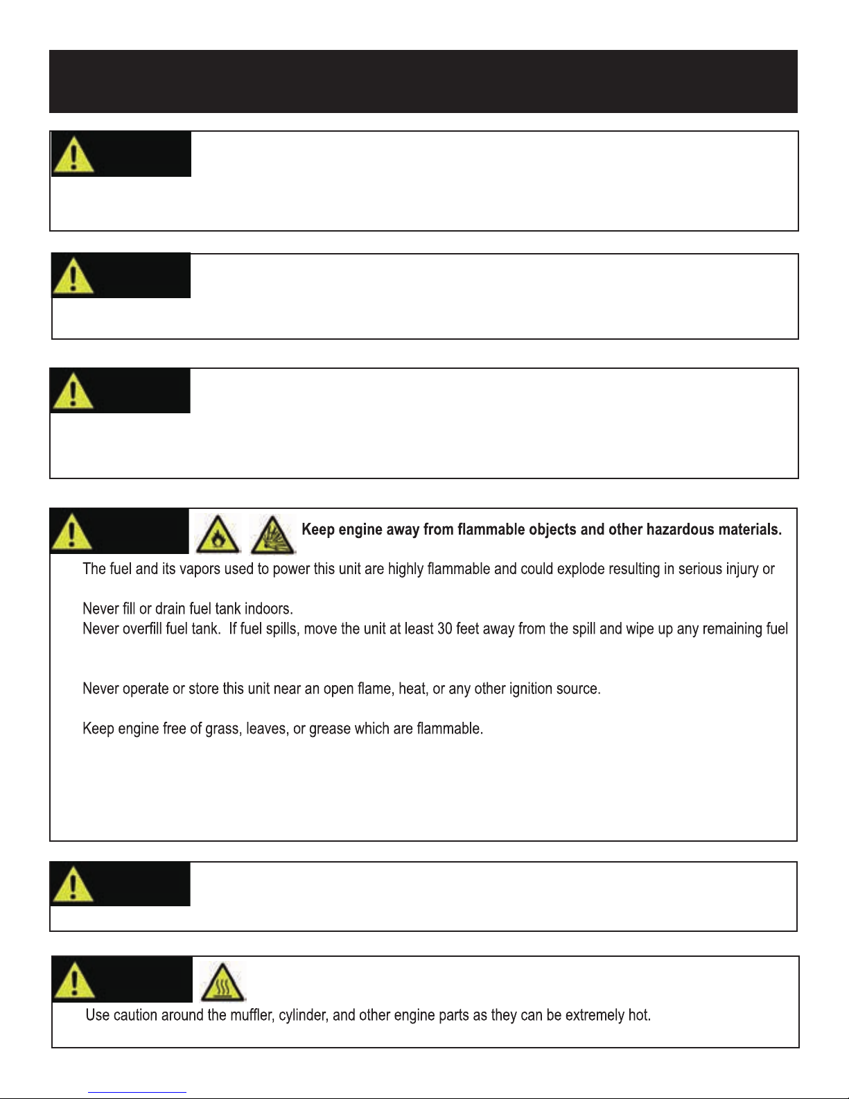
WARNING!
•
death.
•
•
on the unit before starting the engine.
• Never smoke while operating or fueling this unit.
•
• Generator should have at least 5 feet of clearance from buildings or other equipment during operation.
•
• When adding or draining fuel, unit should be turned off for at least 2 minutes to cool before removing fuel cap. If unit
has been running then the fuel cap is under pressure, remove slowly.
• To keep fuel from spilling, secure unit so it cannot tip while operating or transporting.
• When transporting unit, disconnect the spark plug wire and make sure the fuel tank is empty with the 3 in 1 switch is
turned to the off position.
WARNING!
• To avoid recoil, pull starter cord slowly until resistance is felt, then pull rapidly.
Pull cord recoils rapidly and pulls arm towards engine faster than you can let go which
could result in injury.
WARNING!
•
• Allow hot components to cool before touching.
Avoid contacting hot areas of this unit.
5
Page 6
SAFETY RULES
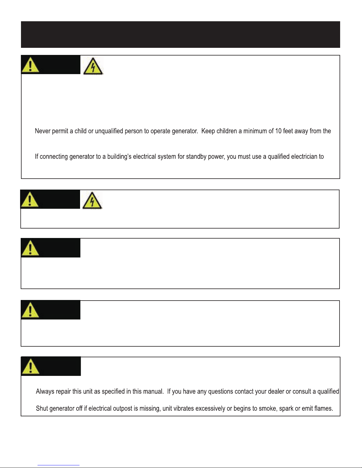
WARNING!
• Never handle the generator, electronic devices, or any cord while standing in water, while barefoot, or when hands or
feet are wet.
• Always keep the generator dry. Never operate generator in rain or under wet conditions.
• Use a ground fault circuit interrupter (GFCI) in a damp or highly conductive area, such as metal decking or steel work.
• Never plug electronic devices into generator having frayed, worn, or bare wires. Never touch bare wires or make
contact with receptacles.
•
generator at all times.
• If using the generator for back up power, notify the utility company.
•
install a transfer switch. Failure to isolate the generator from the power utility could result in serious injury or death to
electric utility workers.
WARNING!
• Only operate generator on a level surface.
• Always connect the nut and ground terminal on the frame to an appropriate ground source.
This generator produces a very high voltage which could result in burn or
electrocution causing serious injury or death.
Generator must be properly grounded to prevent electrocution.
WARNING!
• Increasing governing speed is dangerous which can result in personal injury and / or damaged equipment.
• Decreasing governing speed adds an excessive load and can damage equipment.
• Only when operating at the preset governing speed will this generator supply the correct rated frequency and voltage.
WARNING!
• Do not bypass any safety device. Moving parts are covered with guards. Make sure all protective covers are in place.
• Never transport or make adjustments to this unit while it is running.
• Never insert objects through cooling slots.
WARNING!
• Improper treatment of generator can damage the unit and shorten its life.
•
service center.
•
Never modify this unit in any way or modify governed speed.
Only use this unit as it is intended or serious injury or death could result.
Never operate this unit if there are any broken or missing parts and only use PULSAR PRO-
DUCTS INC. replacement parts specifically designed for this unit.
PROP 65 WARNING: This product contains chemicals known to the state of California to cause cancer and birth defects or
other reproductive harm.
6
Page 7
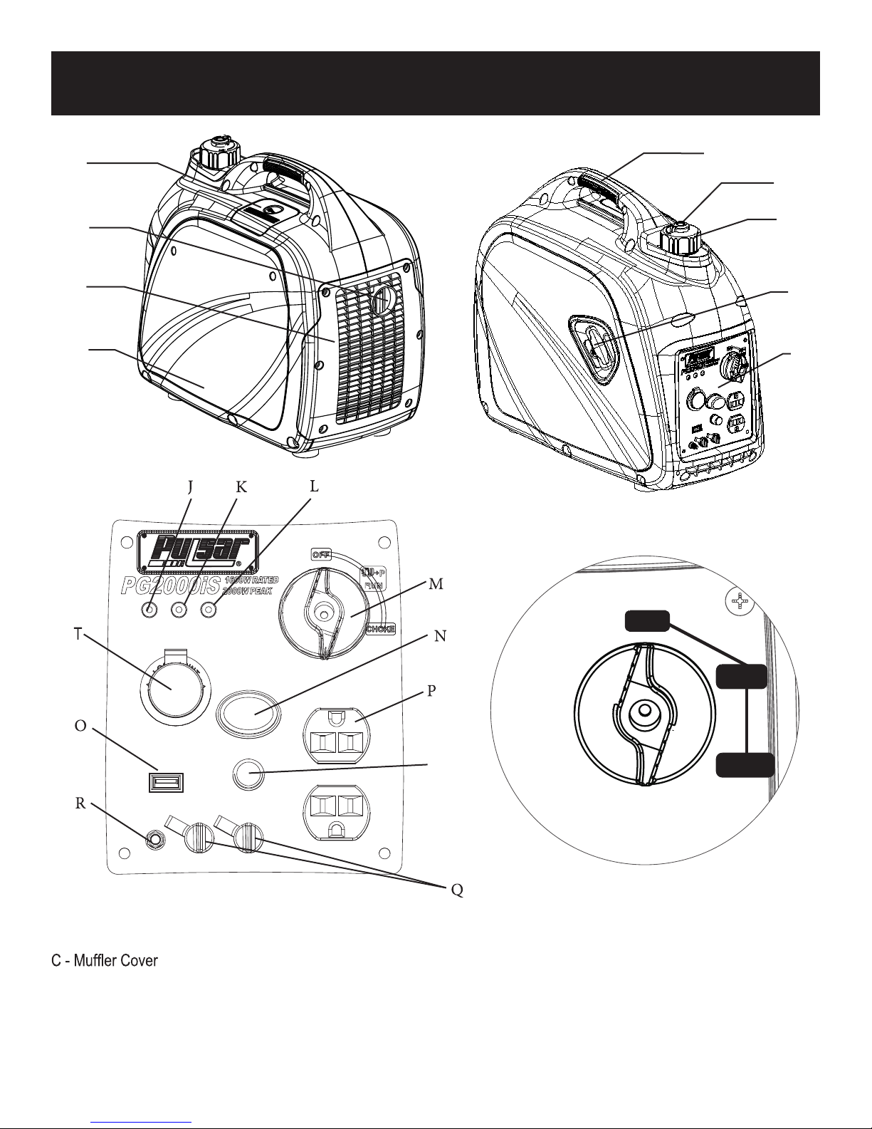
FEATURES
A
B
C
D
E
F
G
H
I
A - Spark Plug Cover
B - Spark Arrestor
D - Outer Casing (Side Panel)
E - Handle (Grip)
F - Air Vent
G - Fuel Cap
H - Recoil Starter
S
I - Control Panel
J - Oil Warning Light
K - Overload Indicator Light
L - AC Pilot Light
M - 3 in 1 Start Switch (RUN / OFF and Choke)
N - Economy Switch
O - USB Outlet 5VDC 1.5A
P - 120V AC 13.3A Duplex Outlet
O FF
RUN
CHO K E
Q - Parallel Outlets
R - Ground Terminal
S - Circuit Breaker AC
T - 12V DC Port
7
Page 8
CONTROL PANEL FUNCTIONS
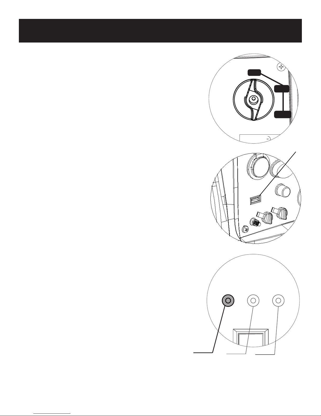
ON/OFF Start Switch and Choke
Start Switch “OFF”
When the Start Switch is in the “OFF” position the fuel valve is
switched off and the engine will not run.
O FF
Start Switch “CHOKE”
RUN
When the Start Switch is in the “CHOKE” position the fuel valve is
switched on and the engine can be started.
Start Switch “RUN”
CHO K E
When the Start Switch is in the “RUN” position the fuel valve is
switched on and the engine can run.
,
Note: The Choke is not required to start a warm engine
USB
USB Outlet
The Generator offers convenient (5V DC 1.5A) U SB outlet to allow
SB GPS, Digital
charging of U
devices like Tabelets, M P3 players,
Cameras and other U SB chargable devices.
Oil Warning Indicator Light
When the oil falls below the minimum level, the oil warning indicator
light comes on and the engine stops automatically. The engine will not
start nutil the proper amount of oil is in the crank case.
Note: If the oil warning indicator light does not come on and the
engine stalls, turn the Start Switch to “
starter.
RUN” and pull the recoil
Engine Overload Indicator Light
If the engine overload indicator light comes on, the generator s wattage
/ amperage capacity has been exceeded by connected electrical
devices or by a power surge. When this occurs, the green AC Pilot
Indicator Light will go off. The engine will continue to run, (but the red
Engine Overload Indicator Light will stay on and power will no longer be
supplied to connected electronic devices.)
How to Correct
1. Disconnect any electronic devices then stop the engine.
2. Reduce the total wattage of connected electronic devices until it is
within the generator’s rated output.
3. Inspect the Air Inlet and Control Panel for any blockage. Remove
blockage if found.
4. Restart Engine.
Oil Warning
Indicator
light
Overload
Indicator
light
AC Pilot
Indicator
light
8
Page 9
CONTROL PANEL FUNCTIONS
Note: The engine overload indicator light may turn on for a few sec-
onds when attaching a load due to a power surge. This is normal.
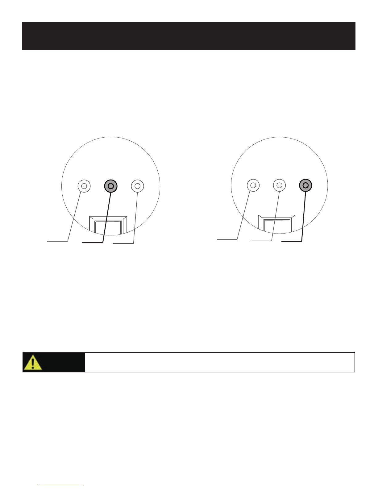
AC Pilot Indicator Light
The green AC Pilot Indicator Light comes on when the engine starts
and generates power.
Oil Warning
Indicator
light
Overload
Indicator
light
AC Pilot
Indicator
light
Oil Warning
Indicator
light
Overload
Indicator
light
AC Pilot
Indicator
light
DC Circuit Breaker
When the DC Circuit Breaker is in the “ON” position, the generator is able to supply power to connected electronic devices.
When the DC Circuit Breaker is in the “OFF” position, the generator will no longer supply power. The DC Circuit Breaker
automatically turns “OFF” when connecting electronic devices to the generator that exceed the generator’s rated output. If
the DC Circuit Breaker turns off, reduce the load of connected electronic devices until the load is within the specified rated
output. To re-establish power, return the DC Circuit Breaker back to the “ON” position.
CAUTION!
If the DC Circuit Breaker turns off again, stop using the generator immediately and consult a
qualified electrician or small Engine repair shop.
Engine Economy Control
• When the Engine Economy switch is turned to the “ON” position, the economy control unit automatically determines the
generator’s proper engine speed based on the connected electronic load. This results in superior fuel economy and
reduces noise.
• When the Economy switch is turned to the “OFF” position, the engine runs at the rated speed of 4,100 r/min.
9
Page 10
CONTROL PANEL FUNCTIONS
Note: The Economy switch must be turned to the “OFF” position when using electronic devices that require a large
starting current, such as a compressor.
Parallel Outlets
Located just above the Ground Terminal, the generator’s Parallel Outlets enable a user to run two PG2000iS generator’s
simultaneously. This operation requires special cables. When operating parallel generators, the rated output is 3.0kVA and
the rated current is 25A/120VAC. For cables and instructions consult a PULSAR dealer for a PARALLEL OPERATION
CCCAAABBBLLLEEE KKKIIITTT...
WARNING!
• Only connect this generator to another PG2000iS Standard Generator.
• Only use a parallel operation cable kit designed to work with this Generator.
Never connect generators that are different models.
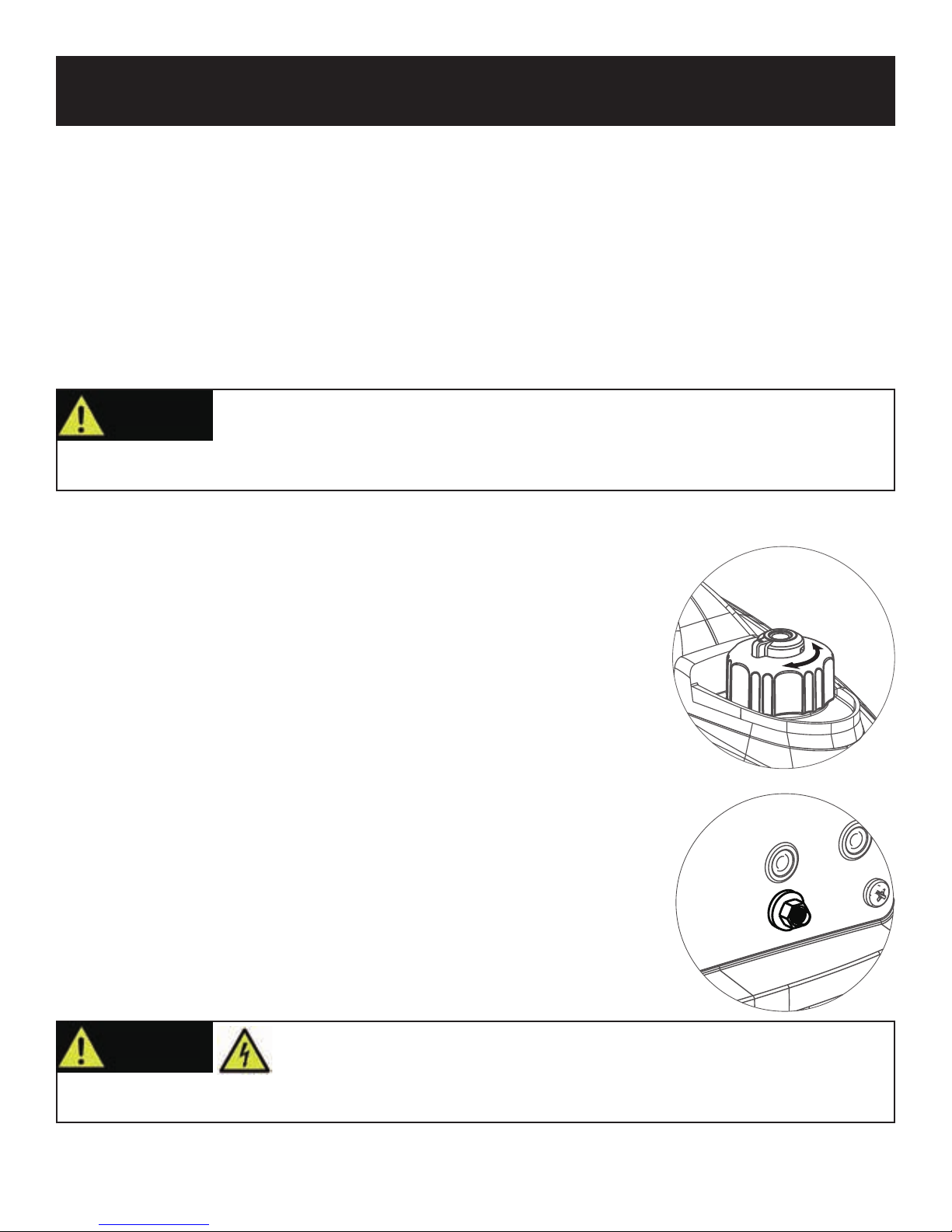
Fuel Cap
Turn counterclockwise to remove the fuel cap.
Fuel Cap Air Vent
The fuel cap is equipped with an air vent to stop fuel from flowing to the
carburetor. The Air Vent must be in the “ON” position to allow fuel to flow
so that the engine can run. Turn the Air Vent to the “OFF” position to stop
fuel flow.
Ground Terminal
The generator’s ground terminal must always be used to connect the
generator to a driven ground rod. Connect the ground terminal to the driven
ground rod with a 12 AWG (American Wire Gage) copper wire. The wire
connects to the terminal between the lock washer and nut. Tighten the nut
securely to ensure good connection. Grounding the generator protects you
from electric shock that results from a build up of static electricity or
undetected ground faults.
OFF
ON
WARNING!
• Only operate generator on a level surface.
• Always connect the nut and ground terminal on the frame to an appropriate ground source.
Generator must be properly grounded to prevent electrocution.
10
Page 11
ASSEMBLY
Connecting Generator to an Electrical System
• If connecting generator to a building’s electrical system for standby power,
The power
from the generator must be isolated from the circuit breaker or alternative
power source. The connection must comply with all electrical codes and
applicable laws.
UNPLUG
Never directly connect generator
to a household power source.
WARNING!
This generator produces a very high voltage which could result in burn or
electrocution causing serious injury or death.
• Never handle the generator, electronic devices, or any cord while standing in water, while barefoot, or when hands or
feet are wet.
• Always keep the generator dry. Never operate generator in rain or under wet conditions.
• Use a ground fault circuit interrupter (GFCI) in a damp or highly conductive area, such as metal decking or steel work.
• Never plug electronic devices into generator having frayed, worn, or bare wires. Never touch bare wires or make
contact with receptacles.
•
generator at all times.
• If using the generator for back up power, notify the utility company.
•
install a transfer switch. Failure to isolate the generator from the power utility could result in serious injury or death to
electric utility workers.
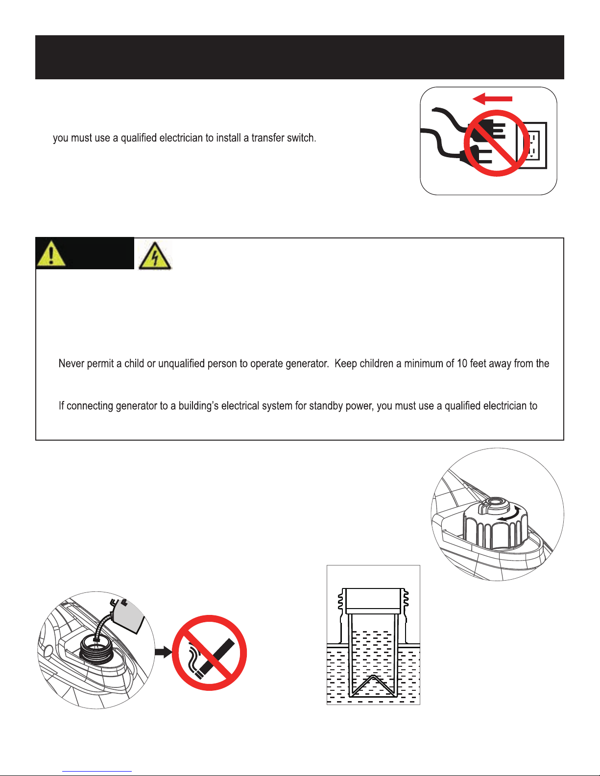
Adding Fuel
• Set generator on a clean and level surface in an area that is well ventilated.
• Remove fuel cap.
• Insert a funnel into the fuel tank and carefully pour gasoline into the tank until fuel level
reaches about 1 ½ inches below the top of the neck. Be careful not to overfill the tank to
provide space for fuel expansion.
• Replace fuel cap and secure tightly.
OF F
ON
Do not smoke when adding fuel.
Turn cap counterclockwise
to remove.
Do not overfill the fuel tank.
P rovide space for fuel expansion.
11
Page 12
ASSEMBLY
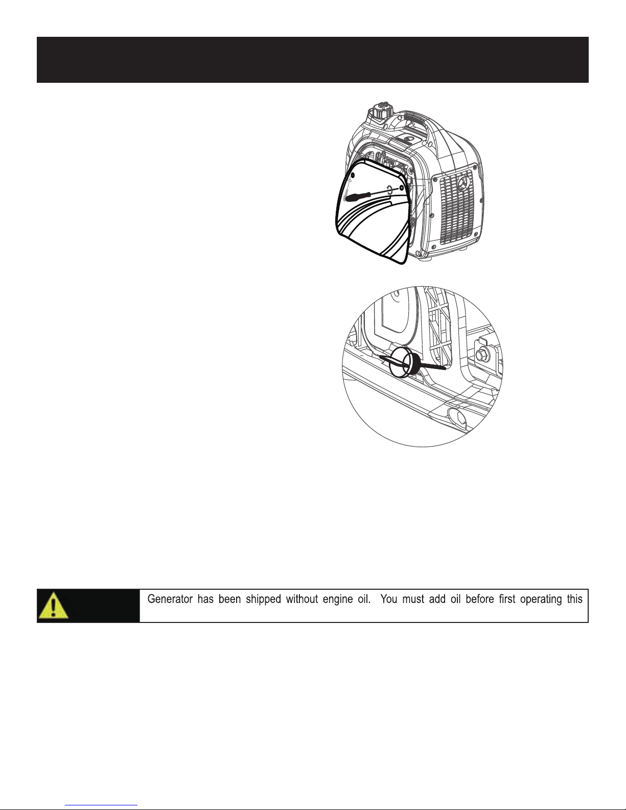
Adding / Check ing Engine O il
• Place generator on a level surface.
• Remove screws and then remove the outer casing cover.
• Remove the crankcase dipstick.
Insert a funnel into the crankcase dipstick hole and carefully add the specified amount of 4-Cycle engine oil (SAE 10W-
•
30) to empty reservoir until or oil reaches the outer edge of the oil fill hole (crankcase dipstick hole).
• Be sure to replace dipstick and securely tighten before attempting to start the engine.
• To check oil, set generator on a level surface, wipe dipstick clean, then reinsert dipstick without re-threading.
Recommended Oil: SAE 10W-30
Oil Capacity: 0.35L (11.8oz)
CAUTION!
generator. Always check oil level before each operation.
12
Page 13
OPERATION
Grounding the Generator
To avoid electrocution, this generator must be properly grounded prior to use. For instructions see Control Panel Functions
pg. 10.
Standard Atmospheric Conditions
Ambient Temperature: 77ºF (25ºC)
Barometric Pressure: 100kPa
Relative Humidity: 30%
Generator output will vary due to changes in temperature, altitude, and humidity. If the temperature, humidity, or altitude are
higher than standard atmospheric conditions, the generator’s output will be reduced. The load attached to the generator must
therefore be reduced.
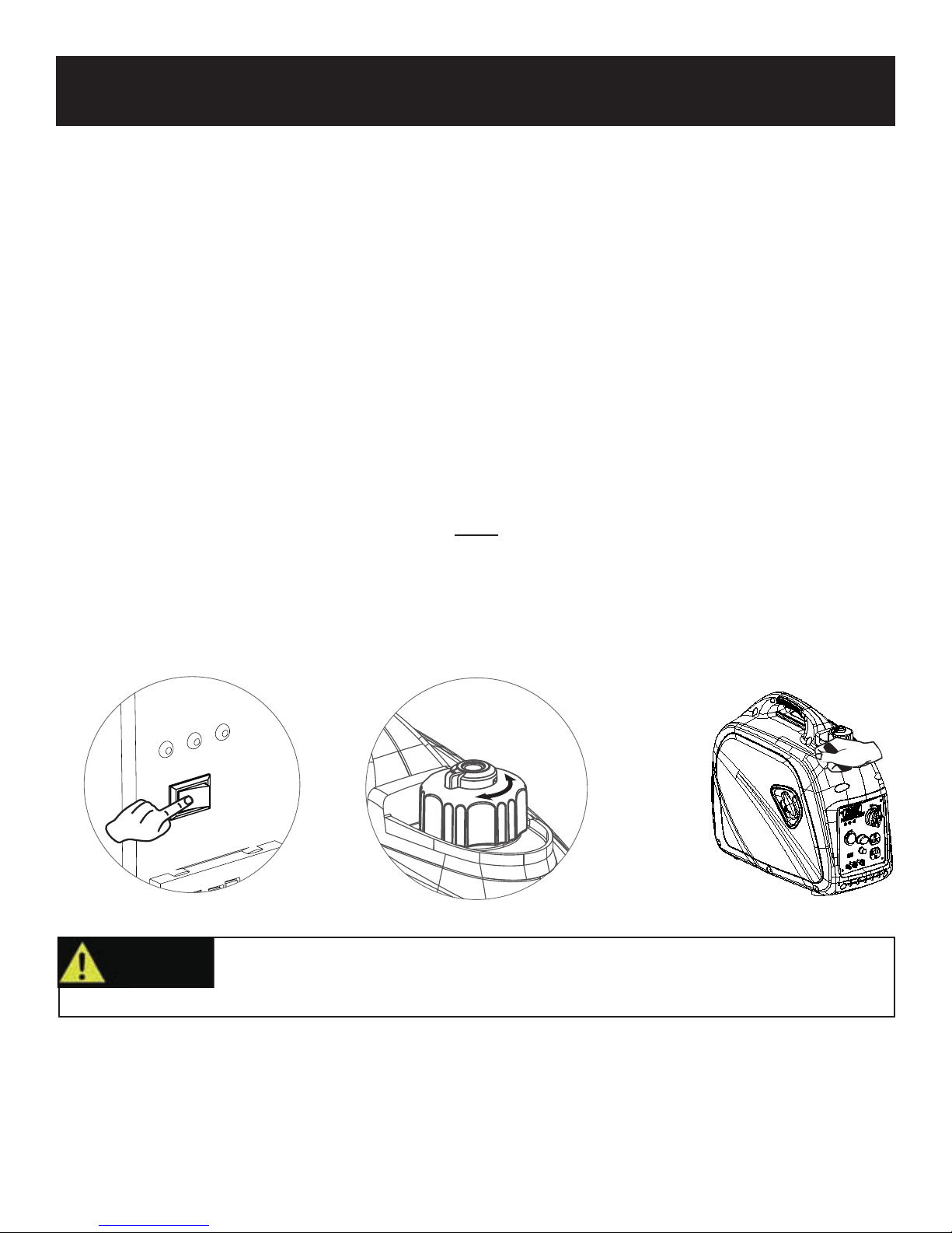
How to Start Engine
• Place generator on a level surface. All electrical loads MUST be disconnected from generator.
• Turn the Economy switch to “OFF”
• Turn the fuel cap Air Vent to the “ON” position.
• Turn the 3 in 1 Start Switch to “CHOKE”
• Pull recoil handle (starter cord) slowly until resistance is felt, then pull rapidly.
• Let engine run for several seconds and then gradually, as engine warms up, turn the 3 in 1 Start Switch to the “RUN”
position.
OFF
WARNING!
ON
Pull cord recoils rapidly and pulls arm towards engine faster than you can let go which
could result in injury.
• To avoid recoil, pull starter cord slowly until resistance is felt, then pull rapidly.
Note: To start the generator with the Economy switch in the “ON” position
• Disconnect all electrical loads from generator.
• If ambient temperature is below 32ºF (0ºC) allow about 3 minutes for the engine to warm up.
The Economy is in “ON” position, the unit returns to normal operation after the above warm up time.
•
• Economy switch must be turned to the “OFF” position when using electronic devices that require a large starting current,
such as a compressor.
OFF
ON
13
Page 14
OPERATION
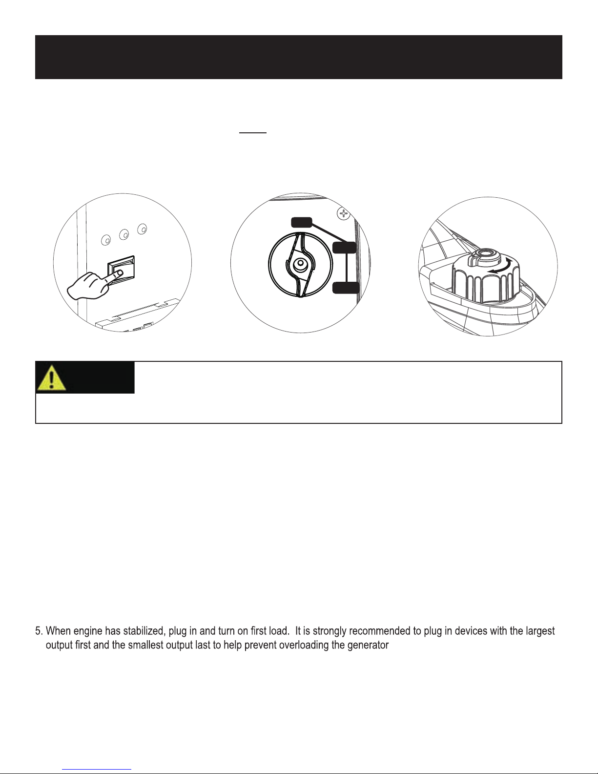
How to Stop Engine
• Turn the Economy switch to the “OFF” position.
• Disconnect any electronic device. All loads MUST be disconnect from the generator. Never start or stop the engine
with electrical devices plugged in to the receptacles.
• Turn the 3 in 1 Start Switch to the “OFF” position.
• Turn the fuel cap Air Vent to the “OFF” position.
O FF
OFF
WARNING!
RUN
ON
CHO K E
Never start or stop engine with electrical devices plugged in to the receptacles. Failure to
OFF
ON
do so could damage the generator and / or connected electrical devices.
• Always start the engine and let it stabilize before connecting any electronic devices.
• Disconnect all electronic devices before stopping the engine.
How to Attach Electronic Devices
1. Before Starting generator
• Make sure the generator is grounded (see page 10 for instructions).
• Make sure the attached load is within the generator rated output and the receptacle’s rated current.
• Make sure all electrical cords and receptacles are in good condition.
• Make sure all electronic devices are turned “OFF” before plugging them into the generator.
2. Start engine
3. If the attached load is small, turn the Economy switch to the “ON” position. For a larger load, or if attaching multiple
electronic devices turn the Economy switch to the “OFF” position.
4. Make sure the green AC pilot indicator light is on.
6. Allow generator output to stabilize (engine and attached devices run evenly) before plugging in the next load.
.
14
Page 15
OPERATION
Charging a 12 Volt Battery
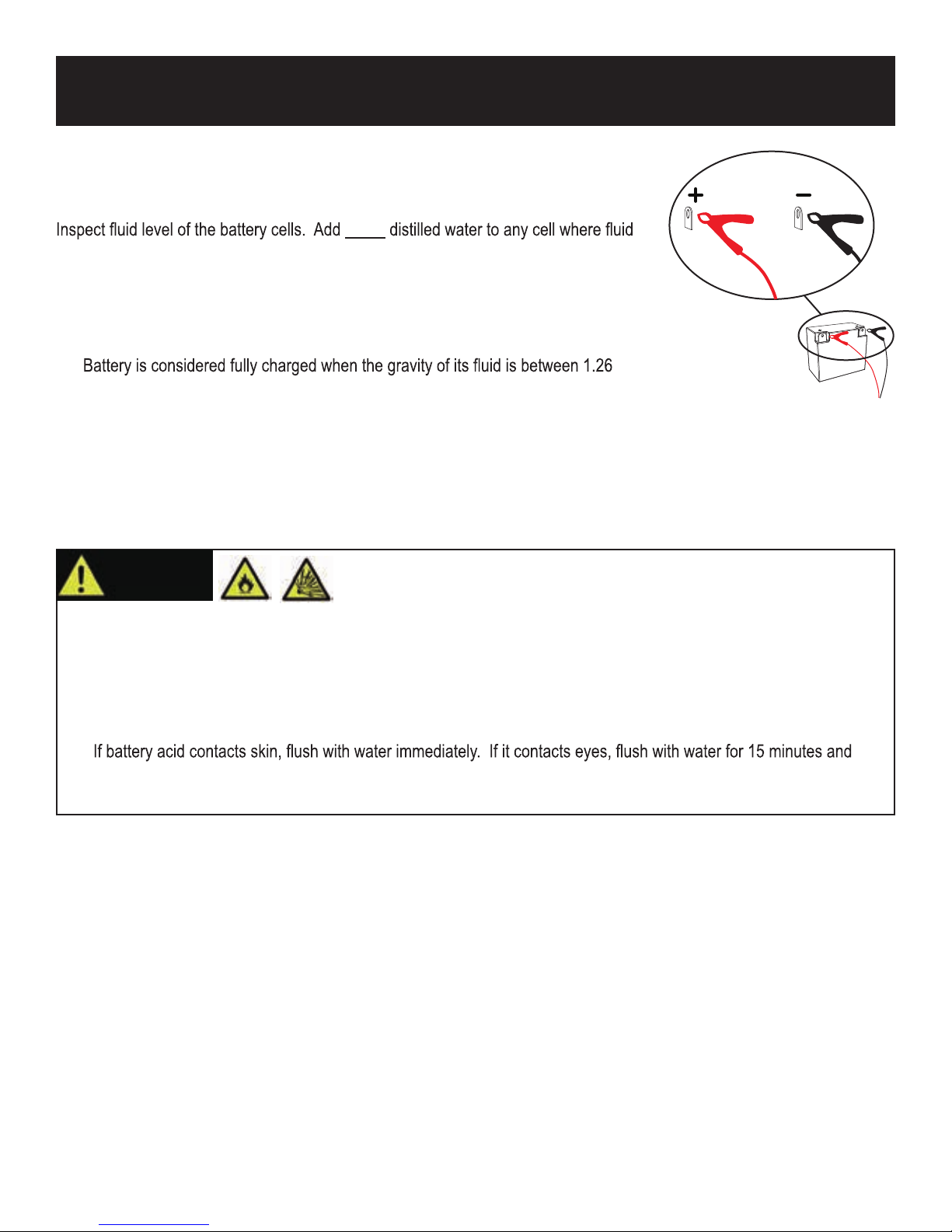
This generator can be used to charge a 12 volt automotive or storage battery by
taking the following steps:
ONLY
level is low. Never add tap water.
1. Use a wire brush to clean battery terminals if corroded.
2. Securely connect the red cable clamp to the positive (+) battery terminal.
3. Securely connect the black cable clamp to the negative (-) battery terminal.
4. Turn the Economy switch to the “OFF” position to start battery charging.
5.
and 1.28 when measured by a hydrometer.
Note: It is strongly recommended to check the gravity level of the electrode at least once per hour with a hydrometer to
prevent overcharging and to test the battery’s condition. Be careful to follow the hydrometer manufacture’s instruction.
WARNING!
• Do not disconnect battery clamps while charging. Batteries produce explosive gasses. Disconnecting the battery
clamps while charging could spark and ignite.
• Do not charge battery in an enclosed area.
• Never smoke while charging the battery or operating or fueling this generator.
• Battery electrolyte contains sulfuric acid. Avoid contact with skin, eyes, and clothing. Always wear eye protection
when charging battery.
•
get immediate medical attention. For internal ingestion, drink large quantities of water or milk, followed by milk of
magnesia, beaten egg, or vegetable oil. Contact a medical physician immediately.
Battery electrolyte is poisonous and dangerous.
15
Page 16
OPERATION
AC Parallel Operation
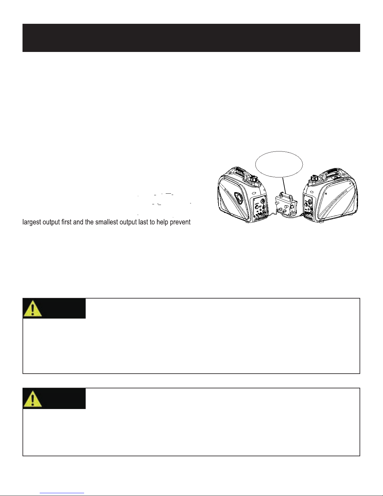
It is possible to connect two PG2000iS generators to each other, using a parallel cable kit, to increase available power output.
• Connect PARALLEL OPERATION CABLES to two
cable kit.
• Make sure the Economy switch is in the same position on both generators.
• All electronic devices should be turned “OFF” and disconnected from generators prior to starting generator engines.
• Start generator engines. Make sure the green output indicator light comes on for each generator.
•
When engines have stabilized, plug in electronic device to AC receptacle and turn on first load.
• Allow generator output to stabilize (engine and attached devices run evenly) before plugging in the next load.
Maximum Power in Parallel Operation: 4.0kVA
Rated Power in Parallel Operation: 3.0kVA
Limit operation time to 3 seconds for load requiring maximum
output. For continuous operation, do not exceed the rated output.
Note: It is strongly recommended to plug in devices with the
PG2000iS generators according to the instructions provided with the
Parallel Box
not included
overloading the generator.
Note: Most electronic devices require power beyond its rated wattage to start. This additional power is referred to as surge
watts and usually lasts between 2-3 seconds. When an electronic device is started, the red overload indicator may come
on. This is normal. If the light stays on disconnect all electronic devices and stop the engine. Refer to “Engine Overload
Indicator Light” on page 8.
WARNING!
• A faulty appliance or power cord can create an electric shock. Do not use electronic devices that have a damaged cord
or plug.
• If an appliance begins to operate abnormally, becomes sluggish, or stalls, turn off and disconnect appliance
immediately. The appliance may have a fault or its rated load capacity exceeds the power supply of the generator.
• To avoid damage to generator or electronic device, do not connect a load to the generator if its electrical rating exceeds
that of the receptacle.
WARNING!
Only connect electronic devices to the generator that are in good working order and do not
exceed the rated power supply of the parallel generators or the desired receptacle.
Never connect generators that are different models.
• Only connect this generator to another PG2000iS Generator.
• Only use a PULSAR approved parallel operation cable kit to connect generators.
• Do not run generators in parallel operation in excess of 30 minutes.
• The parallel cable must be removed if operating only one generator.
• Never disconnect or remove the parallel operation cable while generator is still running.
16
Page 17
OPERATION
Don’t Overload Generator
Make sure you can supply enough rated watts for all electronic devices connected to the generator. Rated watts refer to
the power a generator must supply to keep a device running. Surge watts refer to the power a generator must supply to
start an electronic device. This power surge for starting a device usually lasts between 2-3 seconds but this additional
output must be taken into account when selecting the electronic devices you plan to attach to the generator. To prevent
overloading the generator take the following steps:
1. Add up the total rated wattage of all electronic devices that will be connected to the generator simultaneously.
2. Estimate surge watts by adding the item(s) with the highest output (it is unnecessary to calculate the surge output for all
devices as they should be connected one at a time).
3. Add the Surge Watts to the total Rated Watts in step 1. Keep total load within generator’s power capacity.
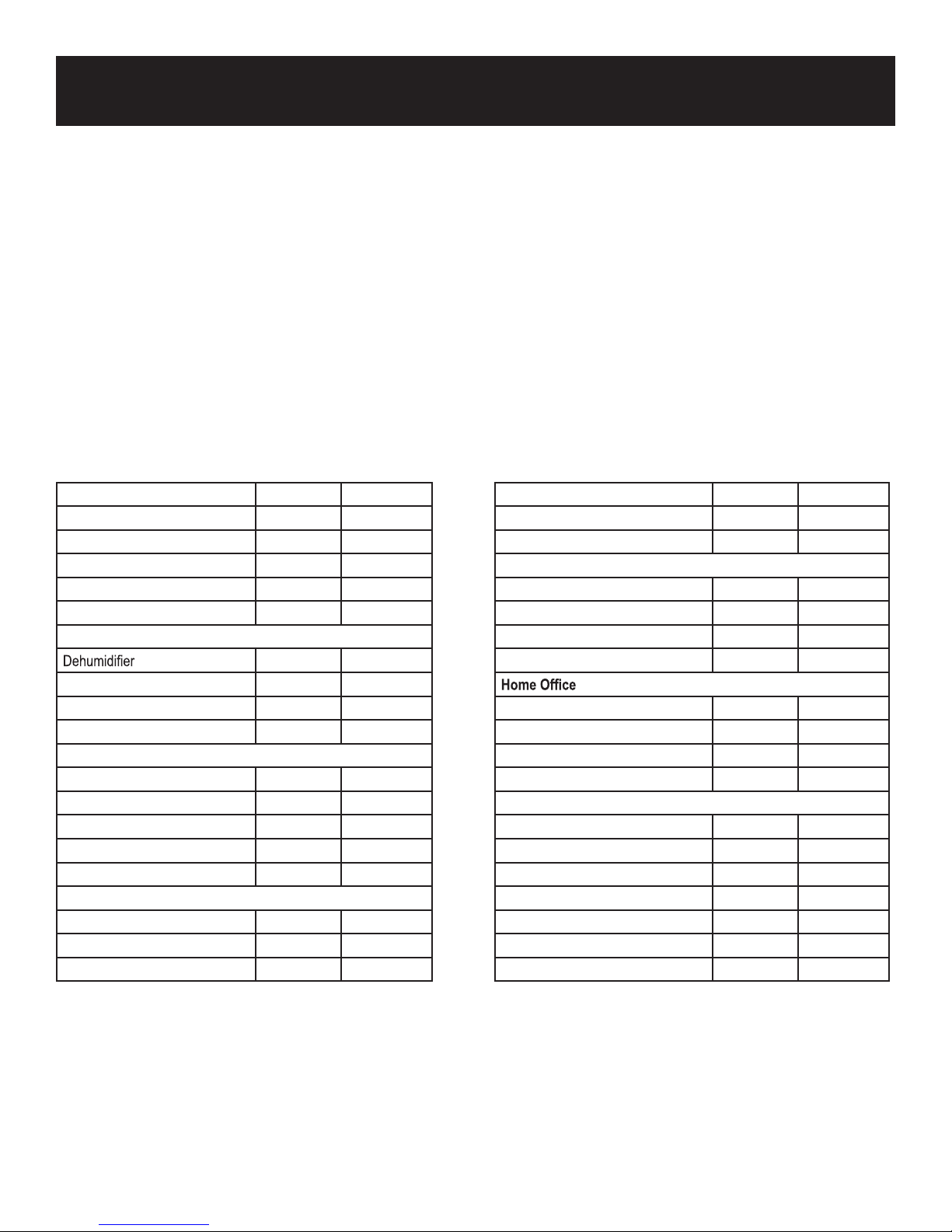
Wattage Reference Guide
(Wattages listed are just approximations. Check electronic device for actual wattage)
Essentials Rated Watts Surge Watts
75W Light Bulbs 75 each 75 each
18 CU Ft Refrigerator / Freezer 800 2200
Furnace Fan (⅓ HP) 800 2350
Sump Pump (⅓ HP) 1000 2000
Water Pump (⅓ HP) 1000 3000
Heating/Cooling
650 800
Table Fan 800 2000
Electric Blanket 400 400
Space Heater 1800 1800
Kitchen
Blender 300 900
Toaster (2 slice) 1000 1600
Coffee Maker 1500 1500
Electric Range (1 element) 1500 1500
Dishwasher 1500 3000
Laundry Room
Iron 1200 1200
Washing Machine 1150 3400
Gas Clothes Dryer 700 2500
Bathroom Rated Watts Surge Watts
Hair Dryer 1250 0
Curling Iron 1500 0
Family Room
X-Box or Play Station 40 0
AM/FM Radio 100 100
VCR 100 100
Color TV (27”) 500 500
Fax Machine 65 0
Personal Computer (17” Monitor) 800 0
Laser Printer 950 0
Copy Machine 1600 0
Power Tools
1000W Quartz Halogen Work Light 1000 0
Airless Sprayer (⅓ HP) 600 1200
Reciprocity Saw 960 0
Circular Saw (7 ¼”) 1400 2300
Mitar Saw (10”) 1800 1800
Table/Radial Arm Saw 2000 2000
Electric Drill (½ HP, 5.4 Amps) 600 900
17
Page 18
MAINTENANCE
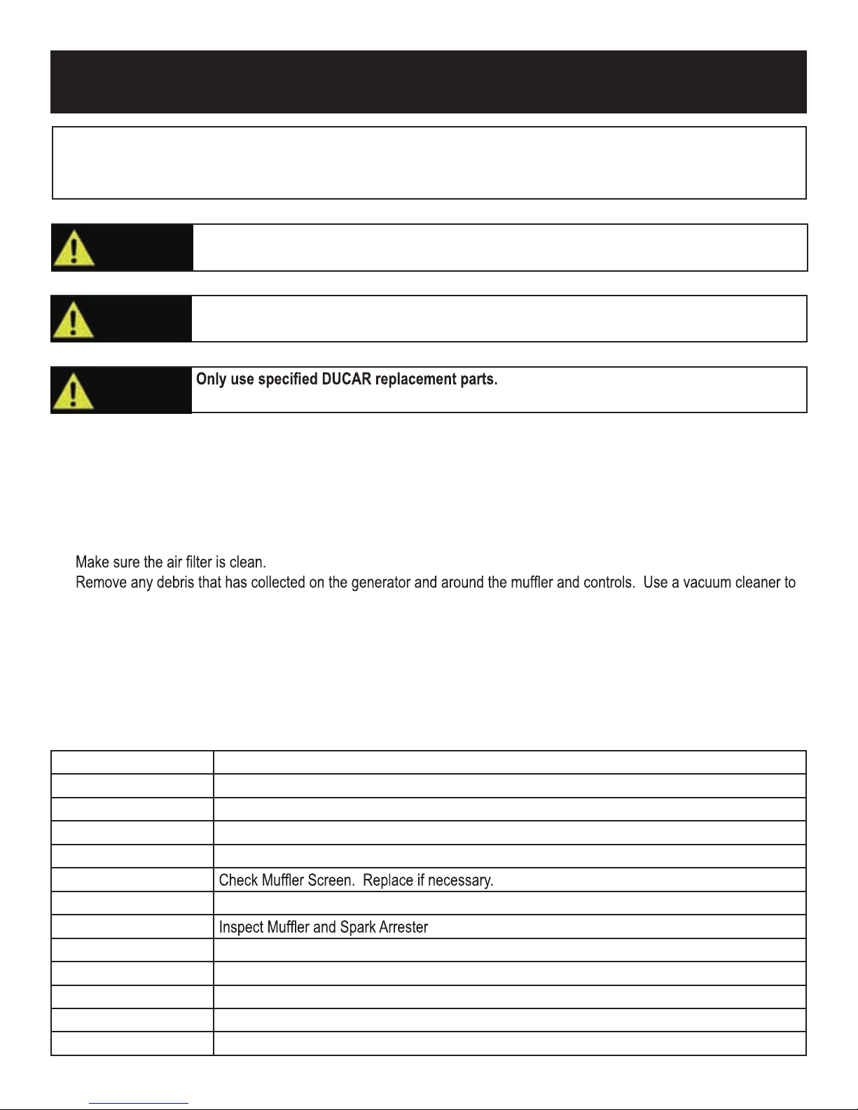
Regular maintenance will extend the life of this generator and improve its performance. The warranty does not cover
items that result from operator negligence, misuse, or abuse. To receive full value from the warranty, operator must
maintain the generator as instructed in this manual, including proper storage.
WARNING!
CAUTION!
Before inspecting or servicing this machine, make sure the engine is off and no parts are
moving. Disconnect the spark plug wire and move it away from the spark plug.
If you are unsure of how to perform a maintenance task, have the unit serviced by a PULSAR
dealer
CAUTION!
Maintenance Schedule
Pre-Operation Steps
Before starting the engine, perform the following pre-operation steps:
• Check the level of the engine oil and the fuel tank level. Check for any leakage.
• Check fuel hose for cracks or damage. Replace if necessary.
•
•
pick up loose debris. If dirt is caked on, use a soft bristle brush.
• Inspect the work area for hazards.
After Each Use
Follow the following procedure after each use:
• Shut off engine.
• Store unit in a clean and dry area.
After First 5 Hours Change Oil.
After 8 Hours or Daily Clean Debris.
Check Engine Oil Level.
6 Months (100 hr Use) Check and Clean Air Filter Element. (Service more often under wet or dusty conditions.)
Change Engine Oil. (Service more often under dirty or dusty conditions.)
Service Spark Plug.
12 Months (300 hr Use) Clean Fuel Filter. Replace if necessary.
Check Crankcase Breather Hose for cracks or damage. Replace if necessary.
De-carbonize cylinder head. See dealer.
Check and adjust Valve Clearance. See dealer.
Check all Fittings and Fasteners. See dealer.
.
18
Page 19
MAINTENANCE
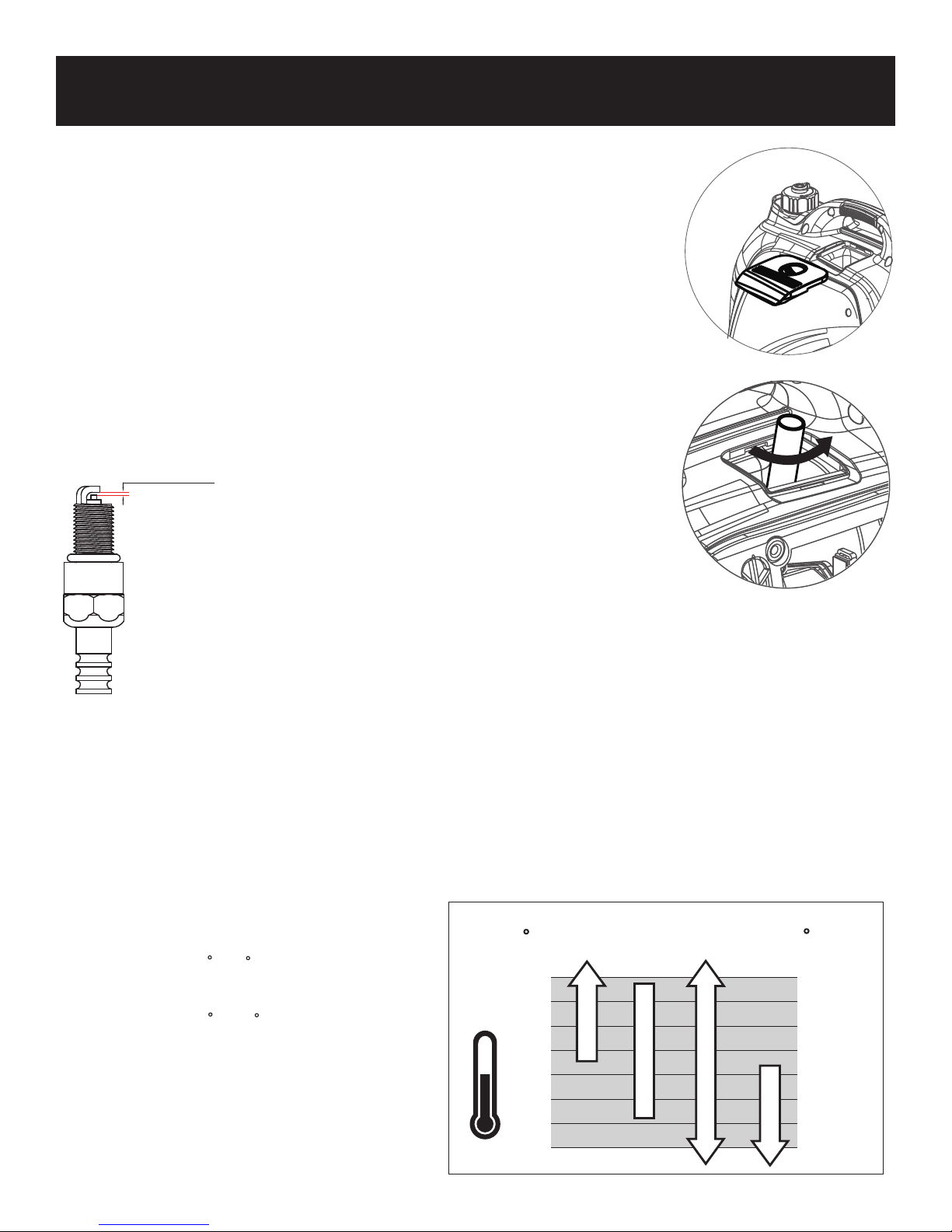
Checking Spark Plug
• Remove cap. Then remove spark plug cap.
• Disconnect the spark plug wire from the spark plug.
• Before removing the spark plug, clean the area around its base to prevent debris from
entering the engine.
• Insert a spark plug socket wrench through the opening on the outside of the cover. Turn
the wrench counterclockwise.
• Check for discoloration and clean carbon deposits off the electrode with a wire brush.
• Check the electrode gap and slowly adjust to 0.6 - 0.7mm (0.024-0.028 in) if necessary.
• Reinstall spark plug and tighten to Torque 20.0Nm (14.8ft-lb).
• If spark plug is worn replace only with an equivalent replacement part. Spark plug
should be replaced annually.
• Reconnect spark plug wire.
• Replace spark plug cap, then replace cap.
0. 6- 0.7mm
Standard Spark Plug: E6TC/E6RTC/BPR6HS
Spark Plug Gap: 0.6 - 0.7mm (0.024
Spark Plug T
orque: 20.0Nm (14.8ft-lb)
-0.028 in)
.
Carburetor Adjustment
The carburetor is low emission and is equipped with a non-adjustable idle mixture valve. If adjustment is needed contact an
authorized dealer.
Oil Recommendations
•
Do not use special additives.
•
Outdoor temperatures determine the proper oil viscosity for the engine. Use the chart to select the best viscosity for the
outdoor temperature range expected.
C
40
30
20
10
0
-1 0
-2 0
5W-30
-3 0
Note:
Below 40 F
*
) the use of SAE 30
(4 C
will result in hard starting.
Above 80 F
*
*
(27
C
the use of 10W-30
)
may cause increased oil consumption.
Check oil level more frequently
F
10 4
86
68
50
32
14
-2 2
*
-4
*
*
SAE 30
10W-30
Synthetic 5W-30
19
Page 20
MAINTENANCE
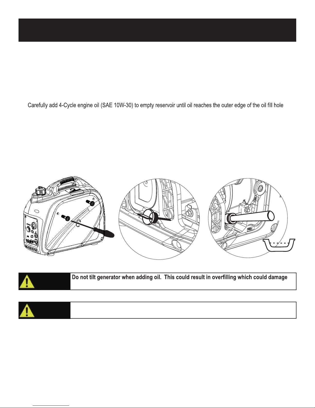
Changing Oil
• Place generator on a level surface.
• Run the generator for several minutes until the engine is warm. Turn off generator.
• Remove screws, then remove outer casing side cover.
• Remove the crankcase dipstick.
• Place an oil pan underneath the engine. Tilt generator to collect used oil. Allow oil to drain completely.
• Return generator to a level surface.
•
(Crankcase Dipstick hole).
• Use a clean rag to wipe up any spilled oil.
• Replace crankcase dipstick.
• Reinstall outer casing side cover and tighten screws.
Recommended Engine Oil: SAE 10W-30
Recommended Engine Oil Grade: API Service SE type or higher quality of engine oil.
Engine Oil Quantity: 0.35L (0.924 US gal)
CAUTION!
CAUTION!
the engine.
Make sure no foreign matter enters the crankcase
20
Page 21
MAINTENANCE
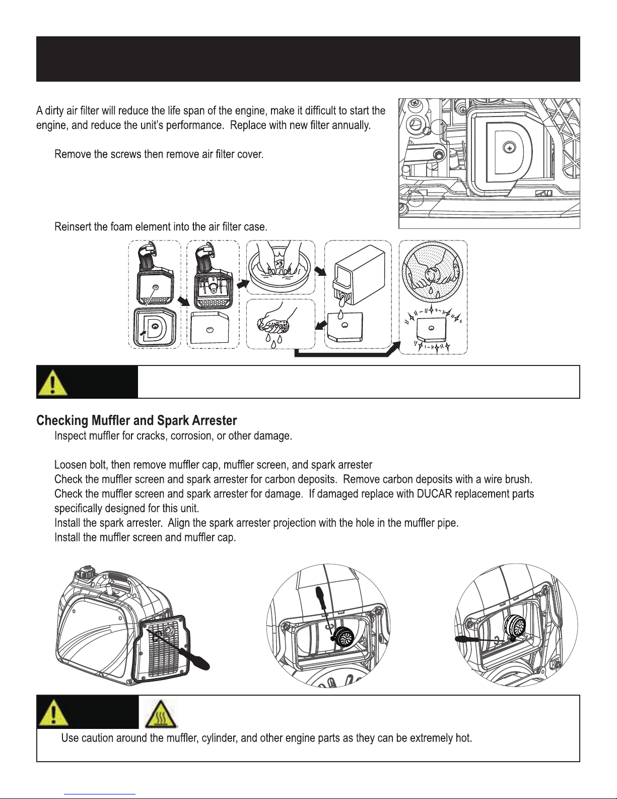
Air Filter
• To clean, remove the screws then remove outer casing.
•
• Remove the foam element.
• Wash the foam element in solvent and let dry.
• Pour a small amount of oil on the foam element then squeeze out, but do not
wring out, excess oil. Foam element should be damp, but not dripping.
•
OI L
CAUTION!
•
• Remove screws, then remove the muffler cover as shown.
• .
•
•
•
•
• Install the outer casing and tighten the screws.
Do not run the generator without reinstalling the foam element or excessive piston and
cylinder wear may result.
WARNING!
•
• Allow hot components to cool before touching.
Avoid contacting hot areas of this unit.
21
Page 22
MAINTENANCE
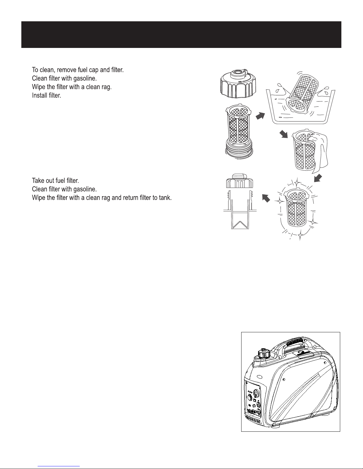
Fuel Tank Filter
•
•
•
•
• Install fuel cap.
Fuel Filter
• To clean, remove screws, remove outer casing, and drain fuel.
• Lift and hold onto the clamp, then remove hose from tank.
•
•
•
• Install hose and clamp.
• Open fuel valve. Inspect for leakage.
• Install outer casing and tighten screws.
Storage and Trans p ortation of th e Generator:
When transporting the generator, turn the 3 in 1 Start Switch (
prevent fuel spillage. Fuel vapor or spilled fuel may ignite.
•
Remove any debris that has collected on the generator and around the muffler and control panel. U se a brush or vacuum
to remove loose dirt.
• Inspect air cooling slots. Remove any debris if obstructed.
For short-term storage, start the generator once every 7 days.
•
• For semi-long term storage, add fuel stabilizer to prevent stale fuel from causing acid and gum deposits in the fuel system
and carburetor.
• For long-term storage, drain the fuel.
• Store indoors to prevent freezing and use aprotective cover to protect from dust.
•
The generator must be Shipped, Run, and Stored in the upright position as seen
in this image.
ON /OFF
and C hoke) OFF. K eep the generator level to
22
Page 23
MAINTENANCE
WARNING!
Contact with a hot engine or exhaust system can cause serious burns or fires. Let the engine cool
before transporting or storing the generator.
CAUTION!
Take care not to drop or strike the generator when transporting. Do not place heavy objects on the
generator.
Engine Long Term Storage:
• Remove the spark plug and pour about 1 teaspoon of 10W30 Engine oil into the spark plug hole. Reinstall the spark plug.
With the 3 in 1 switch in the “OFF” position pull the recoil starter cord several time to coat the cylinder walls with oil.
• Slowly pull the recoil starter until you feel the engine build compression (when you feel resistance). Leave the engine in
this state as this will prevent any corrosion on the cylinder walls if stored for a long period of time.
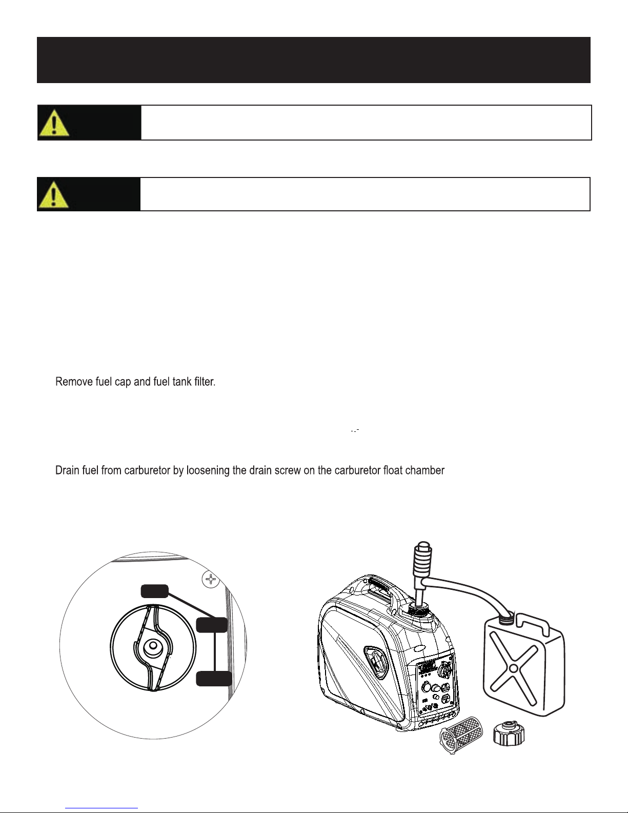
How to drain fuel
• Turn the 3 in 1 switch to the “OFF” position.
•
• Use a siphon to transfer gasoline from generator into a gasoline approved container.
• Wipe up any spilled fuel with a clean rag.
• Start generator engine and let it run until it stops and all remaining fuel is consumed. Do not connect electronic devices
to generator during this process.
• Remove outer casing screws, then remove outer casing.
•
• Turn the 3 in 1 switch to “OFF”
• Tighten the drain screw.
• Install the outer casing and tighten screws.
• When the engine has completely cooled down, turn the Fuel Cap Air Vent to the “OFF” position.
.
O FF
RUN
CHO K E
23
Page 24
TROUBLESHOOTING
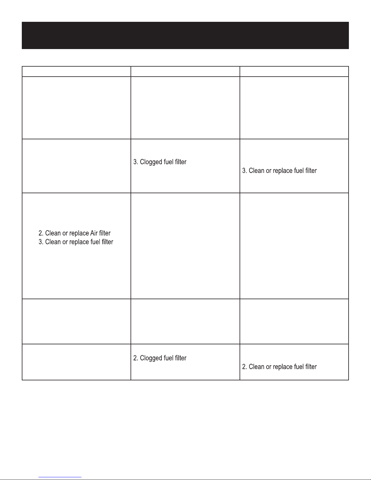
Problem Cause Solution
Generator is running, but does not
supply power.
Engine runs good without load but
bogs down when loads are connected
Engine will not start, shuts down during
operation, or starts and runs rough.
Engine lacks power
1. DC Circuit Breaker is “OFF”
2. Green AC Pilot Light Indicator is off.
3. Poor connection
4. Defective cord set
5. Connected device is faulty
6. Fault in generator
1. Short circuit in connected device
2. Generator is overloaded
4. Engine speed is too slow
5. Short circuit in generator
1. 3 in 1 switch set to “OFF”
2. Dirty Air filter
3. Clogged fuel filter
4. Out of fuel or Stale fuel
5. Spark plug wire disconnected from
spark plug
6. Bad spark plug
7. Water in fuel
8. Overchocking
9. Low oil level
10. Engine has flooded
11. Faulty ignition
1. Generator is overloaded
2.Clogged fuel filter
3.Dirty Air filter
4. Engine needs servicing
1. Turn DC Circuit Breaker “ON”
2. Stop engine and restart.
3. Check and repair
4. Check and repair
5. Connect a device that is working
properly
6. Contact service department
1. Disconnect device
2. See pg 17 “Don’t overload
generator”
4. Contact service department
5. Contact service department
1. Turn switch to “CHOKE” then pull
recoil starter.
2.Clean or replace Air filter
3.Clean or replace fuel filter
4. Replace fuel
5. Reconnect spark plug wire
6. Clean or replace spark plug
7. Drain fuel tank and replace fuel
8. Turn off choke
9. Add oil level.
10. Wait 5 minutes and recrank engine
11. Contact PULSAR dealer
1. See pg 17 “Don’t overload generator”
2.Clean or replace fuel filter
3.Replace Air filter
4. Contact service department
Engine “hunts” or falters 1. Choke was removed too soon
3. Carburetor is running too rich or too
lean
1. Move to choke until engine runs
evenly
3. Contact service department
Page 25
Generator
Engine
Generator Set
DIAGRAMS
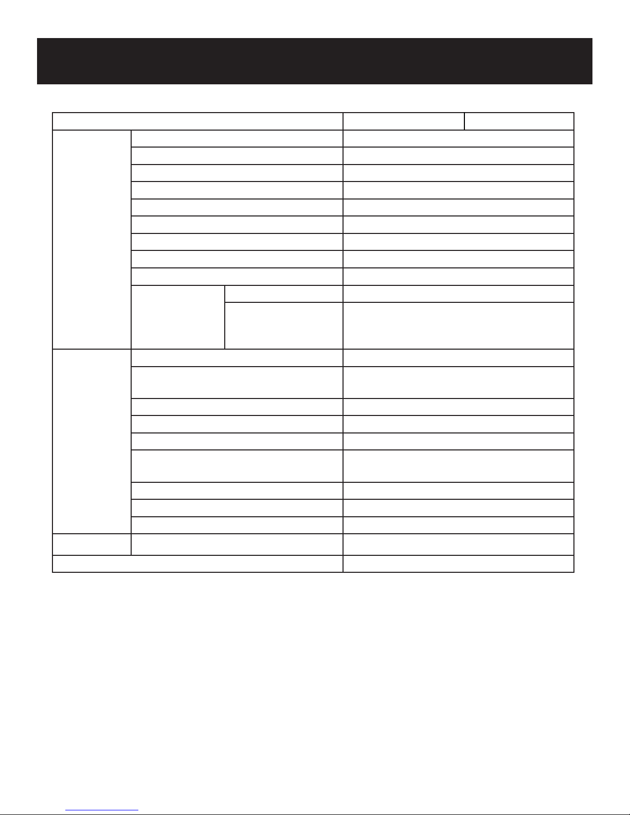
Model No. PG2000i PG2000iS
Type Inverter
Rated Frequency 60Hz
Rated Voltage 120V
Maximum Output Power 2.0kW
Rated Output Power 1.6kW
Power Factor 1.0
AC Output Quality ISO8528 G1
THD% ≤3
DC Output 12V/8A
DC
Overload
Protect
Displacement / cc 80
Fuel Tank Capacity 4.5L / 1.18gal.
Continued Running Time
Engine Oil Capacity 350ml / 11.8oz
Spark Plug Model No. E6TC/E6RTC
Length Width Height / mm
AC
Engine DJ148F
Engine Type
Fuel Type Unleaded Gasoline
(At Rated Power)
Starter Type Recoil Starter
Single Cylinder, 4-Stroke, Forced Air Cooling,
No
Yes
OHV
4hours
499x285x455
Net Weight
Pulsar Products continually seeks advancement in quality and product desing.Therefore, while this manual contains
the most current product information available at the time of printing, there may be minor discrepancies between
your product and this manual. If there is any question concerning this manual, please consult a PULSAR dealer.
This manual should be considered a permanent part of this product and should remain with this product when resold.
Products and specifications are subject to change without notice.
47.1Ibs / 21kg
25
Page 26
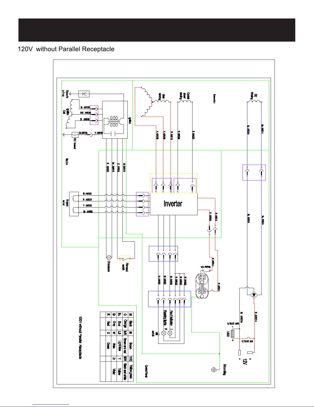
WIRING DIAGRAM
Page 27
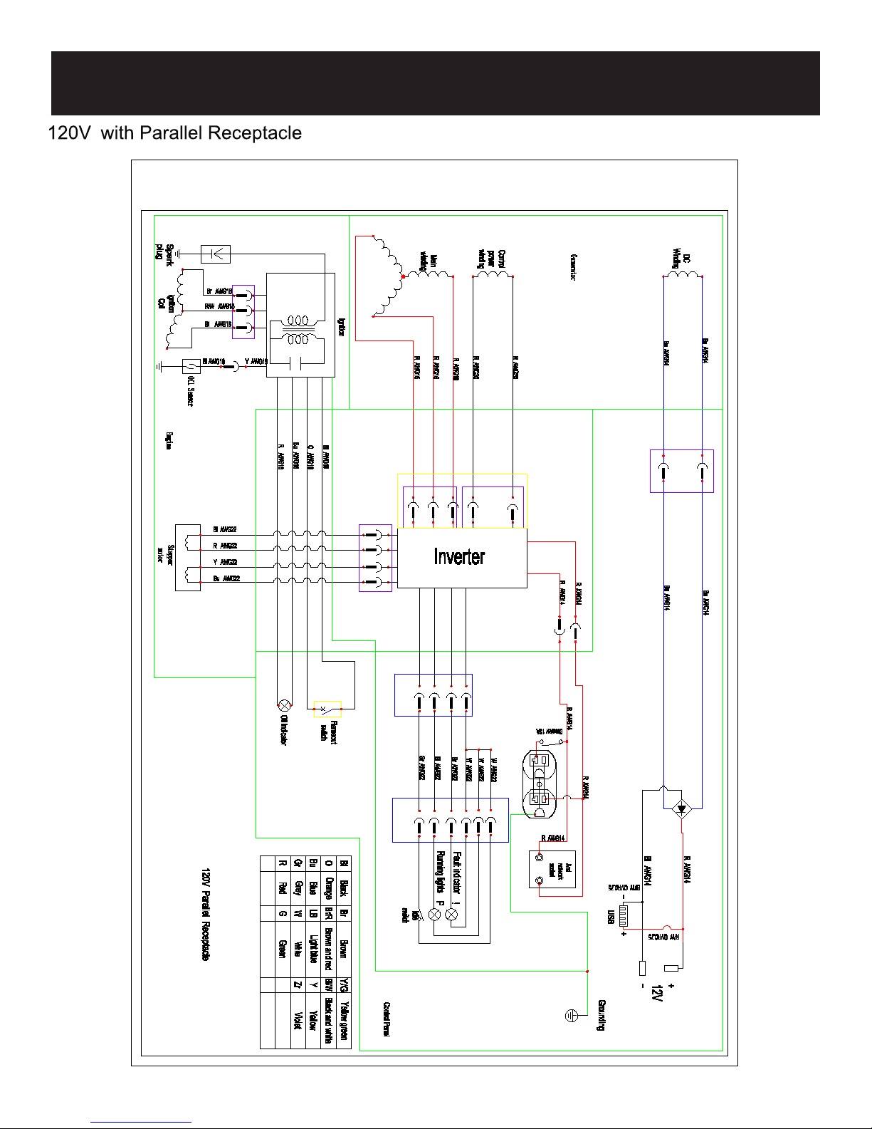
WIRING DIAGRAM
2 7
Page 28

WARRANTY
Limited 2 Y
From the date of original purchase, The warrants to the original purchaser, that each portable generator sold, shall be free
from defect in material and workmanship, for the items and time period set forth below.It at its discretion, agrees to repair or
replace any defective part that upon examination, inspection, and testing by a authorized service dealer, is found to be
defective within the original warranty period. We will also decide upon the use of new or rebuilt parts or comparable product.
Any part or product that is replaced, will be retained by us. This warranty period shall not be extended and any repaired
product shall be warranted for the remaining period of the original warranty. The consumer is responsible, and shall prepay all
transportation costs, including returning items to the factory or warehouse. This warranty is not transferable and proof
of purchase must be presented for requesting warranty service. If proof-of-
shipp
Length of Warranty:
Personal use applications of this portable generator are warranted for two (2) years. Proof of purchase and of
maintenance must be provided.
• Year 1 - Limited comprehensive coverage on all generator components and labor
• Year 2 - Limited coverage on generator engine and electrical components, parts only.
ear Warranty:
purchase or a receipt is not provided, the product’s
ing date by the manufacture will be used to determine the warranty period.
“Personal use” means personal residential household use or recreational use by the retail consumer. “Commercial use” means
all other uses including commercial, construction, or other income producing purposes. Once a generator has been used for
commercial purposes, it shall thereafter be considered as a “commercial use” generator for the purposes of this warranty. Any
portable generator used for commercial use, as rental equipment or for the purpose of primary power in place of utility will not
be covered under this warranty.
Consumer Responsibilities:
• Consumer is responsible for carefully reading and following all instructions in the owner’s manual. Any product that is
damaged due to misuse or abuse will not be covered by this warranty.
• Consumer is responsible for all transportation costs to an authorized Service Center. Unless otherwise requested, ground
shipping will be applied for part shipment and customer will pay any additional charges for expedited shipments.
• Consumer is responsible for labor costs associated with warranted repairs twelve (12) months after the purchase date.
Labor rates will only be based on normal working hours.
•
maintenance may be required to cover warranty requests.
•
Consumer is responsible for presenting any problems with the generator to an authorized PULSAR Service Center as
soon as the problem exists. Warranted repairs will be completed in a reasonable period of time, not to exceed 30 days.
’s manual. Documentation of this
2 8
Page 29

WARRANTY
What this Warranty Does Not Cover:
• Normal wear:
sets, wheels, and starting batteries.
• Maintenance: This warranty does not apply to tune-ups or routine maintenance and does not cover any adjustments or
repairs not performed by an authorized repair facility.
• Misuse: This warranty does not apply if your product has failed due to abuse, misuse, neglect, using incorrect fuels
been operated in any way contrary to the instructions found in the products owner’s manual.
• Adverse conditions: This warranty does not apply if your product has failed due to freezing, accident, natural
disasters.
• Product Shipment: This warranty does not apply to damage resulting from shipping, handling, or warehousing: Any
.
• Other exclusions: This warranty does not apply if your product has been sold “as is” or where the factory applied serial
.
Where Warranty is Valid:
For warranty coverage, this product must be purchased from an authorized PULSAR dealer and the warranty only extends
not covered by this warranty. Products purchased from on-line auction websites, such as ebay, are not covered under this
warranty. Products used for commercial use are not covered under this warranty.
How to Obtain Warranty Service:
Take the original receipt and product to the place of purchase or mail the original receipt and product to the address found
on the web site if purchased on-line. PULSAR recommends you retain all of your receipts covering the purchase and
maintenance of your Portable Generator, but will not deny you warranty coverage as long as proof of purchase or service
can be obtained.
PULSAR ’S OBLIGATION UNDER THIS WARRANTY IS EXCLUSIVELY LIMITED TO PRODUCT REPAIR OR
REPLACEMENT AND SHALL NOT BE LIABLE FOR ANY INCIDENTAL OR CONSEQUENTIAL DAMAGES INCLUDING,
BUT NOT LIMITED TO, THE EXPENSE OF DELIVERING PRODUCT TO AND FROM REPAIR CENTER, LOSS
OR DAMAGE TO PERSONAL PROPERTY, LOSS OF REVENUE, TELEPHONE CHARGES, LOSS OF TIME, OR
INCONVENIENCE. SOME STATES, PROVINCES, OR JURISDICTIONS DO NO ALLOW THE EXCLUSION OR
LIMITATION OF INCIDENTAL DAMAGES, SO THE ABOVE LIMITATION MAY NOT APPLY TO YOU. THIS WARRANTY
GIVES YOU SPECIFIC LEGAL RIGHTS, AND YOU MAY ALSO HAVE OTHER RIGHTS WHICH VARY FROM STATE TO
STATE OR PROVINCE TO PROVINCE.
2 9
Page 30

IM PG2000iS
Rev04 12/6
 Loading...