

Page 1

MICROFLOW-
INSTRUCTION MANUAL
Page 2

Page 3

MICRO FLOW- (FIRST EDITION REV 5)
May 2019
Part Number M-MFi-S-001-5P
COPYRIGHT
© Pulsar Process Measurement Limited, 2017 - 2019. All rights reserved. No part of this publication
may be reproduced, transmitted, transcribed, stored in a retrieval system, or translated into any language
in any form without the written permission of Pulsar Process Measurement Limited.
WARRANTY AND LIABILITY
Pulsar Process Measurement Limited guarantee for a period of 2 years from the date of delivery that it
will either exchange or repair any part of this product returned to Pulsar Process Measurement Limited
if it is found to be defective in material or workmanship, subject to the defect not being due to unfair
wear and tear, misuse, modification or alteration, accident, misapplication or negligence.
DISCLAIMER
Pulsar Process Measurement Limited neither gives nor implies any process guarantee for this product
and shall have no liability in respect of any loss, injury or damage whatsoever arising out of the
application or use of any product or circuit described herein.
Every effort has been made to ensure accuracy of this documentation, but Pulsar Process Measurement
Limited cannot be held liable for any errors.
Pulsar Process Measurement Limited operates a policy of constant development and improvement and
reserves the right to amend technical details as necessary.
The MicroFlow-i shown on the cover of this manual is used for illustrative purposes only and may not
be representative of the actual MicroFlow-i supplied.
TECHNICAL ENQUIRIES
Please contact Pulsar Process Measurement Limited for technical support.
COMMENTS AND SUGGESTIONS
If you have any comments or suggestions about this product, then please contact:
Pulsar Process Measurement Limited
Pulsar Process Measurement Inc.
Cardinal Building
Enigma Commercial Centre
Sandy’s Road
Malvern
Worcestershire
WR14 1JJ
United Kingdom
PO Box 5177
Niceville
FL 32578-5177
USA
Tel: + 44 (0) 1684 891371
Fax: + 44 (0) 1684 575985
Tel: + 1 850 279 4882
Fax: + 1 850 279 4886
Web Site: https://www.pulsar-pm.com
e-mail: info@pulsar-pm.com (general
information)
e-mail: support@ pulsar-pm.com (product
support)
Web Site: https://www.pulsar-pm.com
e-mail: info.usa@pulsar-pm.com (general
information)
e-mail: support.usa@ pulsar-pm.com (product
support)
Pulsar® is a registered trademark of Pulsar Process Measurement Ltd in the UK, USA and China.
Page 4

Page 5

Contents
Chapter 1 Start Here… ....................................................................................................................... 1
About this Manual ........................................................................................................................................... 1
About the MicroFlow-i ................................................................................................................................... 2
Benefits ............................................................................................................................................................ 3
Functional Description .................................................................................................................................... 4
Product Specification....................................................................................................................................... 5
EU Declaration of Conformity ....................................................................................................................... 6
Chapter 2 Installation .......................................................................................................................... 7
Unpacking ........................................................................................................................................................ 7
Power Supply Requirements ........................................................................................................................... 7
Cable Requirements ........................................................................................................................................ 7
Information specific to Hazardous Area Installation ..................................................................................... 8
Limitations on use.................................................................................................................................... 8
Hazardous Area Specific Power Supply and barrier Requirements ...................................................... 9
Location ......................................................................................................................................................... 11
Mounting ........................................................................................................................................................ 11
Angled Mounting Bracket ..................................................................................................................... 12
MicroFlow-i sensor ............................................................................................................................... 14
Mounting sensor to a bracket ................................................................................................................ 15
Terminal Connection Details ........................................................................................................................ 18
Chapter 3 Locating the MicroFlow-i sensor...................................................................................... 19
Locating the MicroFlow-i ..................................................................................................................... 19
Installing the Sensor............................................................................................................................... 22
Preparation for Operation .............................................................................................................................. 23
General Maintenance..................................................................................................................................... 23
Sensor Maintenance. ..................................................................................................................................... 24
Chapter 4 Understanding how the MicroFlow-i operates .................................................................. 27
MicroFlow-i HART compatible ................................................................................................................... 27
4 – 20 mA Device .......................................................................................................................................... 27
Chapter 5 MicroFlow-i HART PC .................................................................................................... 29
Software installation ...................................................................................................................................... 29
Connecting to MicroFlow-i HART PC ........................................................................................................ 30
Flow Tab ........................................................................................................................................................ 32
Configuration Tab ......................................................................................................................................... 33
Parameter Get/Set .................................................................................................................................. 33
MicroFlow-i Manual Setting ................................................................................................................. 34
4 – 20mA Trim ...................................................................................................................................... 35
Trace Tab ....................................................................................................................................................... 36
Comport ......................................................................................................................................................... 38
Language ........................................................................................................................................................ 38
Tools menu .................................................................................................................................................... 38
Info ................................................................................................................................................................. 39
Exit ................................................................................................................................................................. 39
Chapter 6 Parameter Listing and Descriptions .................................................................................. 40
Parameter Access........................................................................................................................................... 40
Device Information Parameters .................................................................................................................... 40
Processing Parameters ................................................................................................................................... 41
MicroFlow-i Firmware Upgrade .................................................................................................................. 44
MicroFlow-i HART Firmware Upgrade ...................................................................................................... 46
Chapter 7 Troubleshooting ............................................................................................................... 48
Chapter 8 Parameter record .............................................................................................................. 49
Chapter 9 Disposal ............................................................................................................................ 50
Page 6

Page 7

Page 1
Chapter 1 Start Here…
Congratulations on your purchase of a Pulsar MicroFlow-i. This quality system
has been developed over many years and represents the latest in high technology
flow monitoring.
It has been designed to give you years of trouble free performance, and a few
minutes spent reading this operating manual will ensure that your installation is as
simple as possible.
About this Manual
It is important that this manual is referred to for correct installation and
operation.
There are various parts of the manual that offer additional help or information as
shown.
Tips
TIP
At various parts of this manual
you may find tips to help you.
Additional Information
Additional Information
At various parts of the manual, you will find sections
like this that explain specific things in more detail.
References
See also text in Bold as these may be references to other parts of this or another
manual.
Drawings
It should be noted that drawings or pictures shown in this manual may not be to
scale.
Page 8
Page 2
About the
MicroFlow-i
The MicroFlow-i is a 2-wire loop-powered non-contacting velocity sensor,
with hazardous area approval. The sensor provides reliable flow velocity
measurements using short pulses of micro-waves, which are transmitted by an
enclosed antenna. When reflected off a moving surface, the signal experiences
a shift in frequency characteristics. The reflected signal is captured by the onboard microprocessor via the antenna, and analysed to determine the velocity.
The MicroFlow-i’s compact and versatile design makes it easy to install and
ideal for confined spaces. Housed in a robust enclosure coupled with a fully
encapsulated microwave antenna, it provides an effective fit-and-forget flow
velocity solution.
Perfect for remote monitoring or when there is no mains power available, due
to its low power consumption. To access flow velocity data, use Pulsar’s
MicroFlow-i HART PC or HART protocol.
Overall the device has outstanding stability, accuracy and repeatability.
Page 9

Page 3
Benefits
Combined with the ease of programming there are many other benefits to using
the MicroFlow-i, these are listed below:
• Non-contact velocity measurement.
• Loop powered and ideal for remote monitoring.
• Low-power consumption.
• Hazardous area approval (Ex ia) for Zone 0.
• ‘See through’ capability for enclosed plastic pipes and concrete (not
reinforced) channels.
• Suitable for abrasive and aggressive materials.
• Resilient to liquid vapour, wind or temperature.
• No minimum liquid level required for measurement
• Maintenance free.
• No interruption to operational flow.
• Can be installed in addition to existing in process contact measuring
devices.
• Easily setup using MicroFlow-i HART PC.
• The sensor is capable of monitoring flow of very shallow liquid,
mitigating the constraint associated with in-liquid techniques.
Page 10

Page 4
Functional Description
Based upon state-of-the-art micro-wave sensing technology, the MicroFlow-i
integrates Pulsar’s innovative and award winning DSP (Digital Signal Processing)
platform, offering you a cost effective solution with excellent reliability and
performance.
The Pulsar MicroFlow-i has been designed to provide maintenance free
performance. The MicroFlow-i i is also intrinsically safe (Ex ia) for Zone 0.
The MicroFlow-i can be mounted via a rear 1” BSP to M20 thread adapter
(supplied with unit). The MicroFlow-i is loop powered and gives a 4 to 20mA
output which is proportional to the flow velocity. A ‘fault condition’ alarm will
give out a reading of either 3.8mA or 22mA.
The 2 wire sensor can either be used in digital HART mode or as 4-20mA loop
powered device. The MicroFlow-i loop powered version can be set up using a
HART modem with either proprietary HART software such as Pact ware or Pulsar
MicroFlow-i HART PC software.
Boot up time from power up to stable reading: cold boot 8.5 seconds, warm boot
4 seconds (if within 12 hours from last start up).
Page 11

Page 5
Product Specification
Physical
Sensor body material Valox 357
Mounting Connection Via 1” BSP back mounted thread, 45o Angled
Mounting bracket and M20 thread adaptor
(optional).
Mounting angle: 45° optimum and mounted at the centre line
of the channel with clear uninterrupted view
Sensor body dimensions Diameter 90mm x height 140mm (3.54in x 5.51in)
Sensor body weight Nominal 0.7kg (1.54 lbs)
Transducer cable extensions 2 core screened
Maximum separation Up to 1000m (3280ft)
Environmental
Enclosure protection IP68
Max. & min. temperature (electronics) -20 ºC to +60 ºC (-4°F to +140°F)
Approvals
ATEX CML 16ATEX2331X, IECEx CML 16.0105X
II 1 G Ex ia IIC T4 Ga
II 1 D Ex ia IIIC T1350C Da
CE and Radar Approval See EU Declaration of Conformity
Performance
Velocity Range 0.2 – 6.0 m/s (0.66 – 19.7 ft/s)
Accuracy The greater of ± 1.5% or 0.05 m/s (0.1ft/s)
Optimum installation Install at an angle of 45° in line with flow. For
more information, see ‘Locating the MicroFlow-i
sensor’ section of this manual
Maximum channel width per sensor 1.5m (4.92ft)
Radar K-Band (ISM)
Transmitter Power <15 dBm
Beam width 20° inclusive
Outputs
Communication HART compatible, 4-20mA loop powered
Programming
PC programming MicroFlow-i HART PC
Programming security via passcode
Programmed data integrity Via non-volatile memory
PC setup and monitoring software compatible Win 7, Win 8, Win 10
Supply
Operating Voltage 10 – 28VDC
Power Consumption Start up = 20mA. Average current = 60µA per
hour when one velocity measurement is
performed every 15 minutes
Pulsar Process Measurement Limited operates a policy of constant development and improvement
and reserve the right to amend technical details as necessary.
Page 12
Page 6
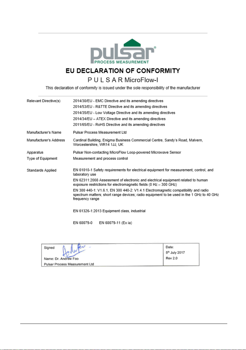
EU Declaration of Conformity
Page 13

Page 7
Chapter 2 Installation
Unpacking
Power Supply Requirements
The MicroFlow-i can operate from a DC supply of 10 to 28V. In all cases the unit
typically consumes 0.52W of power and will typically draw less than 22mA.
Cable Requirements
The MicroFlow-i comes with a fitted integral cable, if this cable is extended then
the total capacitance must not exceed the limits for the voltage applied, and the
hazardous area it is installed in.
The HART modem and PC or HART programmer are used to set up the
operation parameters for the MicroFlow-i sensor. The output can either be as a
4-20mA current giving flow velocity or as a digital signal via a HART master.
The MicroFlow-i cable is a twisted pair with an overall cable screen. The
twisted pair are red and black, connect the red to +ve and the black to the -ve.
The screen should go to signal ground.
Important Information
All shipping cartons should be opened carefully. When using a box cutter,
do not plunge the blade deeply into the box, as it could potentially cut or
scratch equipment components. Carefully remove equipment from each
carton, checking it against the packing list before discarding any packing
material. If there is any shortage or obvious shipping damage to the
equipment, report it immediately to Pulsar Process Measurement Limited.
Important Information
If the equipment is installed or used in a manner not specified in this
manual, then the protection provided by the equipment may be impaired.
Page 14

Page 8
Information specific to Hazardous Area Installation
(Reference European ATEX Directive 2014/34/EU)
The following instructions apply to equipment covered by certificate number CML
16ATEX2331X
1. The equipment may be used with flammable gases and vapours with apparatus
groups IIC, IIB, and IIA with temperature classes; T4 ambient temperature
range -20oC to +60oC.
2. The equipment is only certified for use in ambient temperatures in the range -
20oC to +60oC and should not be used outside this range.
3. Installation shall be carried out in accordance with the applicable code of
practise by suitably trained personnel.
4. Repair of the equipment shall be carried out in accordance with the acceptable
code of practise.
5. Certification as detailed in drawing number D-804-1200 (Ex ia).
6. If the equipment is likely to come into contact with aggressive substances, then
it is the responsibility of the user to take suitable precautions that prevent it
from being adversely affected, thus ensuring that the type of protection is not
compromised.
Aggressive Substances: e.g. such as acidic liquids or gases that may attack
metals or solvents that may affect polymeric materials.
Suitable precautions: e.g. regular checks as part of routine inspections or
establishing from the materials data sheet that it is resistant to specific
chemicals.
7. The certificate number has an ‘X’ suffix that indicates that the following
special condition of certification applies. In the case of the MicroFlow-i
sensor, due to the housing and labels being non-conductive plastic care needs
to be taken with regards to electrostatic charge. The equipment shall not be
installed if the conditions are conductive to the build-up of electrostatic charge.
Additionally, the equipment should only be cleaned with a damp cloth.
Limitations on use
1. The MicroFlow-i must be routinely inspected to avoid the build-up of dust
layers when installed in Zone 21 & Zone 22.
2. Electrostatic hazard – The MicroFlow-i must only be wiped with a damp or
antistatic cloth.
3. The outer enclosure is made from Valox357U, consider the performance of
this material with respect to chemicals that may be present in the hazardous
area.
Page 15
Page 9
Hazardous Area Specific Power Supply and barrier Requirements
The MicroFlow-i operates from a DC supply of 10 – 28VDC and will typically
draw less than 22mA. When connecting sensor to the PC software with a HART
modem, it is recommended to use a supply of at least 18VDC.
The MicroFlow-i cable is a twisted pair with overall cable screen. The twisted
pair is red and black, connect the red to +ve and the black to -ve. The screen
should go to signal ground.
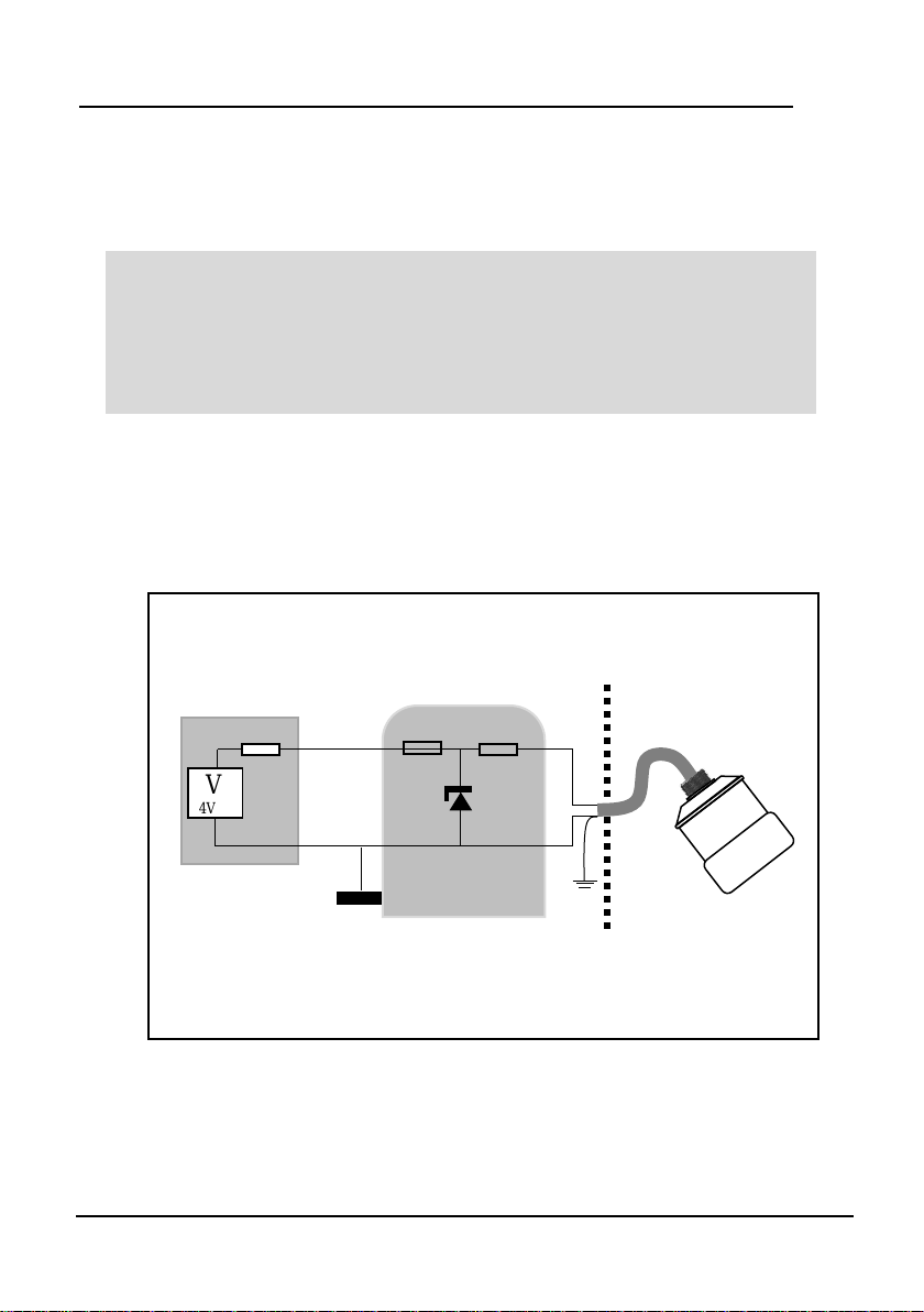
Typical wiring for the MicroFlow-i:
Important Information
In the case of the Ex ia version, the sensor must be powered from an
approved I.S. safety barrier or approved I.S. power supply with the
following limits:
Uo <= 28V, Io <= 162mA, Po <= 1.03W
V
24VDC
I.S. EARTH
PSU/SENSE
LOAD/SENSE
HAZARDOUS
AREA
SAFE AREA
SINGLE ZENNER BARRIER
Ex ia Version 4-20mA mode
SINGLE ZENNER BARRIER
CURENT SENSED IN +ve
Ui<=28V
Li<=162mA
Pi<=1.03W
+
-
Page 16
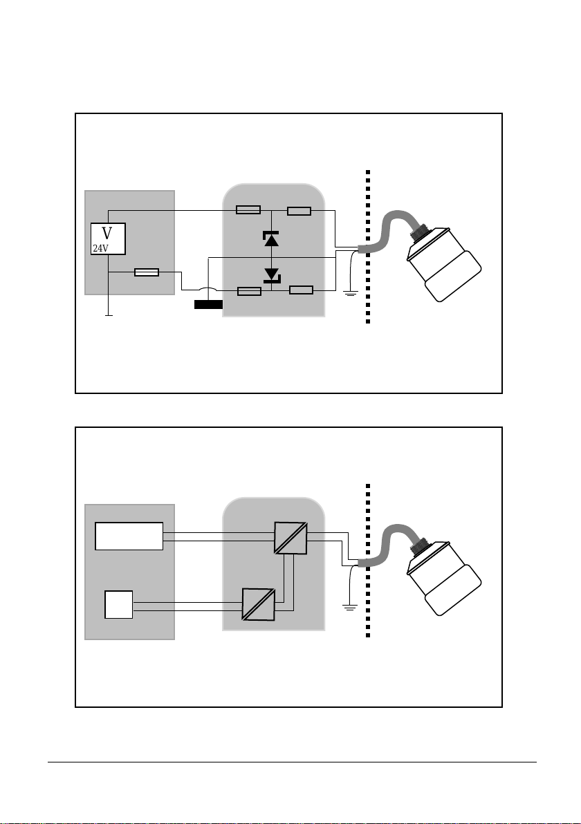
Page 10
V
24VDC
I.S. EARTH
PSU/SENSE
LOAD/SENSE
HAZARDOUS
AREA
SAFE AREA
DUAL ZENNER BARRIER
Ex ia Version 4-20mA mode
DOUBLE ZENNER BARRIER
CURENT SENSED IN +ve
Ui<=28V
Li<=162mA
Pi<=1.03W
+
-
V
PSU/SENSE
HAZARDOUS
AREA
SAFE AREA
GALVANIC ISOLATOR
Ex ia Version 4-20mA mode
GALVANIC ISOLATOR
Ui<=28V
Li<=162mA
Pi<=1.03W
CURRENT
SENSE
+
-
Page 17

Page 11
Location
When choosing a location to mount the bracket and MicroFlow-i, note the
following:
• For optimum readings, it is recommended that the MicroFlow-i should be
positioned at a 45° angle to the surface of the material being measured.
• The mounting surface must be vibration-free.
• The ambient temperature should be between -20ºC and 60ºC.
Mounting
For the best results it is highly recommended to use the MicroFlow-i angled
bracket, which is available from your Pulsar distributor, which will ensure that the
MicroFlow-i can be correctly installed. The bracket can be used if the MicroFlow-
i sensor is to be mounted on its own in a specific location or along with a Pulsar
dBi or dB level transducer. Please see ‘Angled Mounting Bracket’ for
dimensions of this bracket, please note that the drawing is not to scale.
‘Mounting sensor to a bracket’ illustrates how you would install the sensor to
one of Pulsar’s angled brackets.
The MicroFlow-i angled bracket should be mounted by marking and drilling the
holes suitable for fixing your screws/bolts (length to suit your application) and
then fixing the bracket in place.
Important Information
When installing the MicroFlow-i it is recommended that it is mounted at
least 1m away from moving persons or machinery.
All electronic products are susceptible to electrostatic shock,
so follow proper grounding procedures during installation.
Page 18

Page 12
Angled Mounting Bracket
Part number: dBA0008MF
45
o
Side view
176mm
22mm
22mm
R20mm
12mm
100mm
Top view
100mm
Page 19

Page 13
Important Information
Using a spirit level, ensure that the Mounting Bracket is level before
attaching the sensor to the bracket.
R20mm
4 off 12mm
14mm
100mm
60mm
20mm
20mm
100mm
60mm
26mm
Rear view
Page 20

Page 14
MicroFlow-i sensor
The dimensions of the sensor body are shown below in Fig.1 and Fig.2:
BOTTOM
90 mm
1” BSP
78 mm
39mm
140 mm
To obtain the most accurate results, ensure the device is mounted at
a 45° angle to the surface being measured.
45°
Surface of measurement
73 mm
M i
Green ‘Dot’ to be
positioned on top of sensor.
Fig.1
Fig.2
Page 21

Page 15
Mounting sensor to a bracket
Mounting the sensor to the 45° angled bracket is done via an adapter and M20 nut, as
shown in Fig.3:
For correct installation, we recommend that the adapter is threaded on the cable, and
carefully screwed onto the MicroFlow-i before fitting to the bracket. This will reduce
the risk of any ’twisting’ in the cable.
Ensure that the sensor is tightened and the dot is in the correct position.
Important Information
When fixing the sensor to the adapter, ensure that care is taken when
pulling the sensor cable through. And once attached to the adapter, and
the M20 nut is tightened, the green dot should be central to the
movement of flow as shown in Fig.4.
Bracket
Adapter
Fig.3
Cable
M20 Nut
Green dot to be
displayed on top
Page 22

Page 16
Care should be taken not to overtighten the sensor when everything is connected,
as seen in Fig.5 below, as this could cause damage to the housing.
Central to the movement
of flow in channel.
Fig.4
Fig.5
305mm
215mm
129mm
Page 23

Page 17
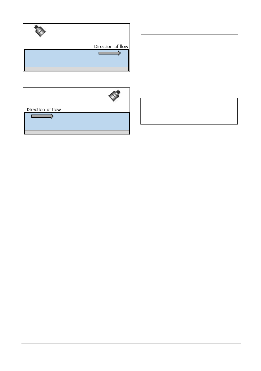
When the sensor is mounted on the bracket with dB or dBi series level
transducer, you can position the bracket in a way where the MicroFlow-i is
obtaining measurements following the direction of the flow, or facing the
direction of flow. Fig.6 and Fig.7 illustrate the correct positioning of the devices
according to the direction of flow:
Green dot to be
displayed on top
Direction of flow
Fig.6
Direction of flow
Fig.7
Green dot to be
displayed on top
Page 24

Page 18
Terminal Connection Details
Terminal Connections
Power
The MicroFlow-i operates from a DC voltage supply of 10-28 volts, and should
be installed and connected in accordance with ‘Chapter 2–Power supply
requirements’ and the instructions below. When wiring the MicroFlow-i you
should use a twisted pair cable. The wire coding is shown below for ease of use
when connecting the MicroFlow-i to monitor flow velocity:
You can also use Pulsar’s MicroFlow-i HART PC software to interrogate and
obtain readings from the device. Please refer to Chapter 6 MicroFlow-i HART
PC for more details on how to use it.
Important Information
If the equipment is installed or used in a manner not specified in this
manual, then the protection provided by the equipment may be impaired.
Bootlace
Ferrules
MicroFlow-i cable
110 mm
Heat Shrink
Power +10-28 VDC (Red cable)
0 Volts (Black cable)
Screen (Green cable)
Page 25

Page 19
Chapter 3 Locating the MicroFlow-i sensor
For optimum accuracy install the MicroFlow-i where the flow is not turbulent.
An ideal location for the sensor is in the centre of a long straight channel.
Vertical drops, baffles, curves or junctions can cause the velocity profile to be
distorted.
To obtain optimum results in velocity readings, the MicroFlow sensor requires
surface ripples to be present to provide a reliable measurement. If there are not
any surface ripples within the sensors field of view under ant flow conditions,
then an alternative measurement point should be found, or ripples created.
Locating the MicroFlow-i
• If the width of the channel exceeds 1.5m. Multiple MicroFlow-i sensors
are required to be used in conjunction with the Ultimate Controller with
firmware version 1.5.2 and later.
• When a level measurement transducer is used and mounted on the same
bracket as the MicroFlow-i. Take into account, the ‘blanking’ distance of
the transducer when mounting the bracket for the application.
• Ensure that there is an unobstructed path between the sensor and the surface
of the moving liquid being measured.
• Position the sensor at a height of 250mm above maximum liquid level or up
to two times the channel width from the minimum liquid level, whichever is
greater. As shown in Fig.8 below:
• A = Minimum 250mm above Maximum Liquid level.
• B = Maximum 3m above Minimum Liquid Level.
Important Information
If the maximum water height exceeds 2x width of the channel OR
If the maximum water height in channel is less than 50% of the
width of the channel. Please consult Pulsar product support for
assistance.
Fig.8
B
A
Max Liquid
Level
Min Liquid
Level
MicroFlow
Page 26
Page 20
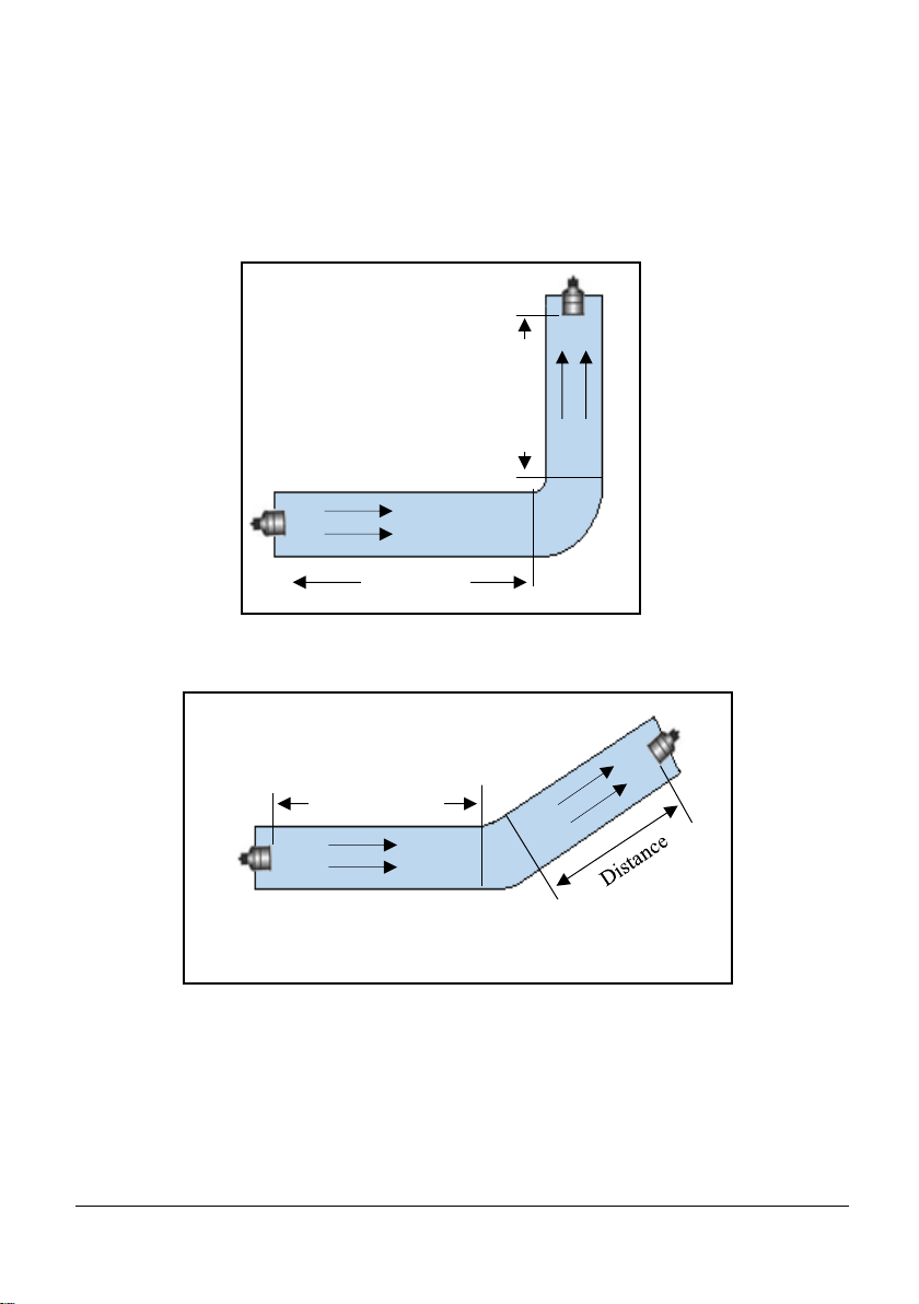
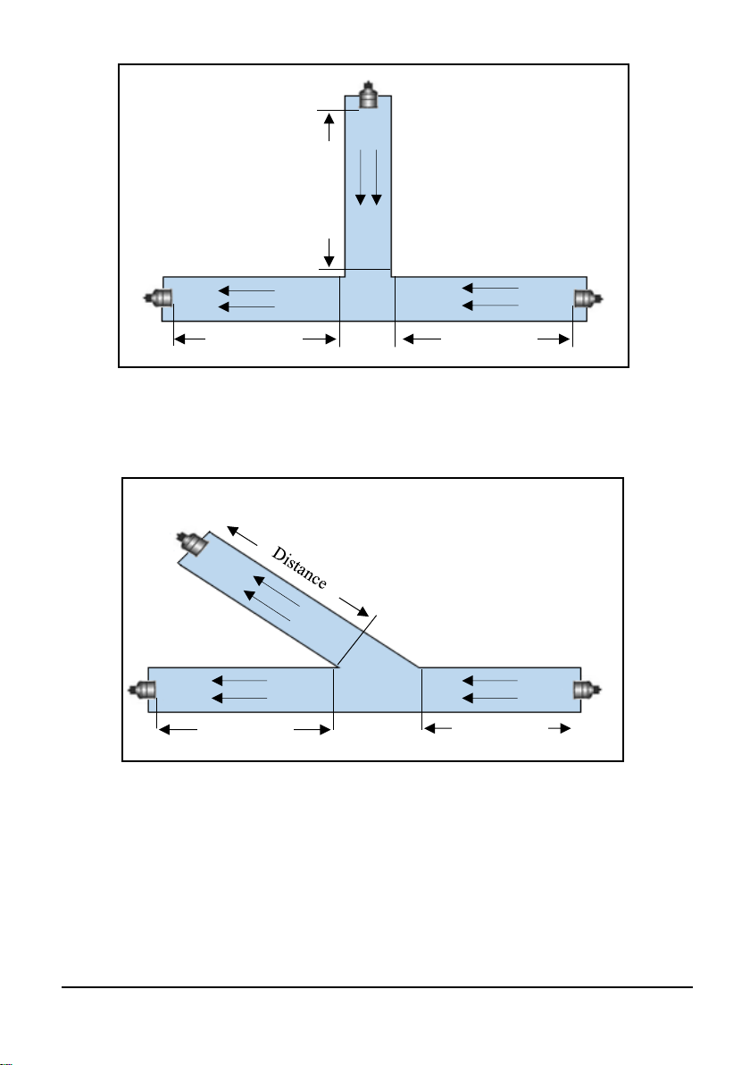
• In the instance where there are vertical drops, baffles, curves or
junctions. The sensor should then be positioned on a straight part of
the channel, at a minimum distance that is at least five times the width
of the channel before a bend, in order to obtain optimal velocity
readings. Examples of positioning the sensor are shown in diagrams 1 - 4
below:
Distance
Distance
Diagram 1
Distance
Diagram 2
Page 27
Page 21
Diagram 4
Diagram 3
Distance
Distance
Distance
Distance
Distance
Page 28

Page 22
Installing the Sensor
• The sensor is supplied with a 1” BSP to M20 thread adapter. The Sensor
housing is designed to accept a 1” BSP female threaded coupler for pipe or
conduit.
• Ensure that the sensor is positioned at a 45° angle to the surface of the
measured application, as this will achieve the best results. An example of
this is shown in the diagram below:
• When using one of the Pulsar Angled Mounting Brackets, secure the bracket
using the correct size screws/bolts/U-bolts (12mm diameter thread).
• Tighten the sensor into the bend, and then screw the thread adapter onto the
bracket using the nut supplied. CAUTION: extreme over-tightening may
crack or cause damage to the unit or bracket.
• Position the sensor so the green ‘dot’ that is shown on the label between the
two green arrows is on the top of the device, and is central to the movement
of flow in the channel.
• If desired, the sensor cable may be extended up to a maximum of 1000m.
Install the sensor cables in grounded metal conduit. Do not run in cable trays
or duct banks with variable frequency drives or other high voltage sources.
• When extending cable for a MicroFlow-i sensor, ensure that all wiring in any
junction /connector boxes are correct.
• Attention should also be taken, when mounting the unit, to ensure that strong
windy conditions are avoided wherever possible to prevent abnormal
operation.
• The sensor can be positioned to obtain readings following the direction of the
flow. Or it can be positioned to measure the oncoming flow as seen below:
45°
Surface of measurement
Green dot to be
displayed on top
Page 29
Page 23
Preparation for Operation
Before switching on, ensure that the following is checked:
✓ The MicroFlow-i is mounted correctly and is secure as outlined in
Chapter 3 – Locating the MicroFlow-i sensor.
✓ All wiring is correct.
✓ The power supply is correctly installed.
General Maintenance
There are no user serviceable parts inside MicroFlow-i. If you experience any
problems with the unit, then please contact Pulsar Process Measurement for
advice.
To clean the equipment, wipe with a damp cloth. Do not use any solvents on the
enclosure.
MicroFlow-i obtaining readings
following the direction of the flow.
MicroFlow-i obtaining readings
from the oncoming direction of the
flow.
Page 30

Page 24
Sensor Maintenance.
Procedure for the Removal of a MicroFlow-i Sensor
From time to time it may be necessary to remove the sensor for cleaning or
maintenance purposes, the below procedure is to ensure that this is done carefully
with regard for the health and safety of the operator involved, and without damage
to the sensor.
If it is necessary to replace the sensor for any reason, the following procedure
should be followed:
• Disconnect the power supply to the sensor.
• Remove any fittings that the sensor may be attached to, allowing the cable to
be pulled through with ease.
• If using a Pulsar angled bracket, the sensor head is mounted onto the end of
the bend via its process fitting, this should be carefully unscrewed in an
anticlockwise direction. Ensure that the sensor is not dropped or knocked as
this can cause damage to the unit.
• When replacing the sensor, care must be taken not to over tighten the unit as
this can cause damage. Hand tight is sufficient.
• Ensure that the green dot has been positioned in the direction of the flow of
the vessel, this will obtain optimum velocity readings that are available.
Please refer to ‘Fig.3’ in ‘Chapter 2-Installation’ section on how to do this.
• When the sensor has been replaced for the application, and re-connected to a
controller and the power re-applied, the unit will re-initialise and will begin
the process of acquiring flow and velocity readings.
• When refitting or replacing a sensor, ensure that it is installed in accordance
with ‘Chapter 2-Mounting a sensor to a bracket’.
• When replacing the sensor for a new one, you can use MicroFlow-i HART
PC to upload any changed parameters from your old sensor to the new sensor.
Allowing continued use of the sensor which is setup for your application.
The correct PPE should be worn on site when performing maintenance on the
system, if in doubt please contact your site Health and Safety Officer for further
advice.
Important Information
Before attempting to remove the sensor for cleaning or any other
purpose, the power to the unit should be disconnected.
Page 31

Page 25
To remove the sensor, first loosen any glands, couplers etc. that may connect it to
the Mounting Bracket, and then lift the sensor body onto a safe place. Taking care
not to damage the sensor housing or cable whilst performing this removal.
The sensor can then be safely inspected for damage or material fouling and can be
carefully cleaned with a damp cloth to remove any foreign debris.
Important Information
Care should be taken when removing and cleaning so as to not damage
the device.
Page 32

Page 26
This page is left blank intentionally
Page 33

Page 27
Chapter 4 Understanding how the MicroFlow-i operates
In order to initially set up the MicroFlow-i (if required) to obtain readings from
your application, it is advised to do this using MicroFlow-i HART PC.
Once the MicroFlow-i has been powered up, you can now begin to obtain flow
velocity from the sensor.
MicroFlow-i HART compatible
The MicroFlow-i uses a unique protocol which enables it to be compatible to any
HART controller that it is connected to, the HART address is ‘0’.
4 – 20 mA Device
The MicroFlow-i can be used as an ‘out of the box’ 4 – 20mA device, this is the
case, by default when you switch the sensor on. The 4 – 20mA output is
proportional to the flow velocity being seen, with respect to the maximum range
of the sensor up to 6 m/s (19.7 ft/s).
Important Information
For further information on how to set up the sensor as a mA device,
please contact your local Pulsar distributor.
To enable the MicroFlow-i to work successfully, ensure
that the power is disconnected prior to a connection being
made.
Page 34

Page 28
This page is left blank intentionally
Page 35

Page 29
Chapter 5 MicroFlow-i HART PC
The software that accompanies the MicroFlow-i can be used to access and change
all parameters via the HART modem, test, obtain and record trace readings from
a sensor. To utilise the features of the software, a USB HART modem which is
available from Pulsar (as shown in Fig.9 below), is required to communicate
between the sensor and your machine.
Software installation
Insert the CD that accompanies the MicroFlow-i sensor into your PC/Laptop. If
you do not have a CD drive on your laptop, then this software can be downloaded
from the Pulsar Process Measurement website: www.pulsar-
pm.com/support/downloads/software.aspx and choose to download MicroFlow-i
HART PC from the list which will then be downloaded onto your machine.
When setting up the HART modem for the first use, you will need to install the
necessary drivers for it to operate correctly with your OS. These drivers can be
installed from your installation disc. Run the MicroFlow-i HART PC Setup.exe
from the CD, or from the downloaded file from our website to install the
MicroFlow-i HART PC software correctly, which will automatically install the
necessary drivers for your HART modem. Once downloaded, a shortcut icon will
be created onto your Desktop for ease of use. Double click on this icon to launch
the program.
Important Information
For optimum installation insert your HART modem to your PC whilst
installing MicroFlow-i HART PC, where your PC should then assign
the modem to a Com Port. Or if you have an internet connection,
upon inserting the USB of the HART modem for the first time,
Windows updates should install this onto your computer for you.
Once the driver’s installation has completed, remove the HART
modem from your machine. Your modem is ready to be used when
a connection to MicroFlow-i PC is required.
Fig.9
Page 36

Page 30
Connecting to MicroFlow-i HART PC
When connecting to the software using the HART modem, power to the sensor
can be obtained from a 10-28VDC source.
To enable the MicroFlow-i to work correctly please ensure that the sensor is wired
as shown in the picture below:
To enable the sensor to work correctly, the power (red) cables from the supply and
to the MicroFlow-i must be wired in series with the 250 Ohm resistor (as seen in
the above picture).
Once the sensor is connected to the HART modem, insert the USB into the
PC/laptop ready for use. You can now use MicroFlow-i HART PC to change
settings of the sensor to suit your application.
To make a connection to the MicroFlow-i sensor, supply power to the sensor and
then select the button which will change to ‘Scanning’ and
the following pop-up windows will appear during an initial connection:
Important Information
Ensure that power to the sensor is switched ‘OFF’ before removing
cables and any connection is made.
Power (+) to MicroFlow-i
(Red cable)
0V to MicroFlow-I (Black cable)
Power (+) from supply
(Red cable)
0V from supply
(Black cable)
250 Ohm resistor
Connector
Connector
Page 37

Page 31
Once the MicroFlow-i parameters have been retrieved successfully, the status
condition will then appear as below:
Page 38

Page 32
If the sensor fails to connect to the software, please check that the Comport has
been correctly set (details of how to do this is outlined in this chapter). After
launching the program and connecting to the MicroFlow-i, the device’s
parameters will be automatically extracted once a connection is established.
Once connected you can now view the information received from the sensor on
the Software’s individual tabs: Flow, Configuration and Trace.
appears after a connection is established, selecting this will then
disconnect the MicroFlow-i.
Flow Tab
The above picture is an example of the default screen of MicroFlow-i HART PC,
which is the Flow tab. The dial on the left displays the linear flow velocity of a
maximum up to 6m/s (19.7 ft/s). While the numerical display on the right shows
the velocity flow rate and the current mA reading.
Signal Strength
The signal strength gives an indication of the actual strength of the velocity signal
detected. A level of higher than 70% is desired for reliable operation.
Page 39

Page 33
Stability
The stability level is an indication of the consistency of flow reading, as derived
from the combination of signal strength and statistical fluctuations of the flow
reading. A high level of stability would indicate optimum condition, and relatively
healthy flow within the channel and indicate higher levels of repeatability and
better flow tracking. The stability does not necessarily indicate the accuracy of
the flow reading, as this is subject to calibration.
Configuration Tab
Parameter Get/Set
This feature allows you to obtain and change parameter values from the list
available. Further information of these parameters and their values can be found
in Chapter 7 – Parameter Listing and Descriptions.
Get:
This will read and display the current ‘Value’ of the parameter selected, along with
‘Units’ of measurement where used, and a brief description of the parameter
selected. Select the desired parameter from the drop down ‘Parameter’ box and
select ‘Get’
Page 40

Page 34
Default:
When selected, this will display the current parameters default value. Selecting
‘Set’ will change the parameters value to that of its default value.
Set:
Allows the value of the selected parameter to be changed. Select the desired
parameter from the drop down ‘Parameter’ box, enter the required value and select
‘Set’. The value box will turn green when the change of parameter value has been
successfully carried out.
MicroFlow-i Manual Setting
The option for manually setting the parameters can be done by utilising the Manual
Setting terminal, as shown below:
This feature is also available when the sensor has been set into ‘Program mode’,
where all if the MicroFlow-i parameters can be queried by entering the parameter
address in the Parameter field and then clicking on the ‘Get’ button. The
MicroFlow-i will then reply with the current value of that parameter.
Selecting ‘Get’ will read and display the current value of the MicroFlow-i
parameter selected. When ‘selected, within the terminal box you will see a
command appear, example <</p102 as the software queries the chosen parameter.
The unit will reply with the parameter and its current value, example: ==/p102:120
Selecting ‘Set’ allows the value of the selected MicroFlow-i parameter to be
changed, both the address and value must be entered before clicking on the button.
<</p102:100 will show the parameter number and the value you have changed in
the manual setting box. And ==/p102:140 will appear when the change of the
parameter and its value is complete. The appropriate access levels are required for
setting parameters.
The values need to be valid and within the allowed range for that particular
parameter for the change to be successful. Please refer to ‘Chapter 7 Parameter
listing and Descriptions’ in this manual, on the parameters available and the
range each one can be set between. If a parameter has been incorrectly set, choose
the parameter from the options in ‘Parameter Get/Set’ and select the default button
to display the default value for that parameter. Pressing set will revert the
parameter to its default value.
Page 41

Page 35
4 – 20mA Trim
This feature is only available to use when the sensor has been set to ‘Run mode’,
the options will then no longer be greyed out and will now be available to use.
If the device connected to the mA output is out of calibration, and is unable to be
calibrated. Then the low and high current levels can be calibrated by altering ‘Set
4mA’ (Low Trim) and ‘Set 20mA’ (High Trim). It is advised that to carry out
calibration, that a Digital Multi Meter (DMM) is used, so that 4mA or 20mA
respectively are shown on the device.
Calibrating 4mA
To calibrate the 4mA, type in ‘4’ in the ‘Constant mA’ value box and press ‘Send’.
If the low value reading is incorrect, then it can be trimmed using the ‘Set 4mA’
option. Enter the offset directly into the value box and then select the ‘Set 4mA’
button to enable you to get the expected result (reading).
Calibrating 20mA
To calibrate the 20mA, type in ‘20’ in the ‘Constant mA’ value box and press
‘Send’. If the high value reading is incorrect, then it can be trimmed using the
‘Set 20mA’ option. Enter the offset directly into the value box and then select ‘Set
20mA’ button to enable you to get the expected result (reading).
Resume mA
When calibration is complete, to release the constant mA reading select ‘Resume
mA’ which will return you to normal measurement/mA output readings. If this is
not selected when calibration is complete, then your mA output will not be
updated.
Page 42
Page 36
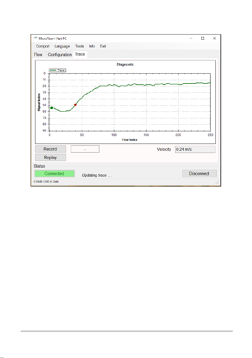
Trace Tab
Upon opening the trace tab, the information at the bottom of the screen will scroll
through Measurement in progress, Updating mA, Updating Trace. Once the trace
has updated the diagnostic traces from the sensor will be displayed. You are also
able to see the current velocity measurement obtained by the sensor.
The vertical axis is related to the signal strength, while the horizontal axis is related
to the detected flow.
When a signal is received, the ‘green square indicator’ will move down from 10
on the vertical axis. The further the ‘green square indicator’ moves from 10, the
larger the strength of the received signal. During flow condition, the ‘green
square indicator’ will normally be within the range of 30 to 70. Under no-flow
conditions the ‘green square indicator’ will remain at 10.
When flow is detected, the ‘red circle indicator’ will move horizontally to
indicate flow detection. The ‘red circle indicator’ should stay at 0 under no-flow
conditions, and move along the horizontal axis when flow is detected.
Under flow condition, the line should still approach and flatten out at just below
the signal index 10 line. If the trace remains flat or the indicators struggle to
remain stable during flow, then increase the ‘Gain’ (P102) setting.
Page 43

Page 37
You can zoom in by clicking and holding the mouse to draw a box over the
region to zoom in on. Zooming out can be done by right clicking on the chart and
selecting “Undo All Zoom”.
Record Traces
To record traces and the current velocity, select the button and enter
a site ID when prompted to do so. The record button will then change to green
whilst the software is recording the data from the sensor. A new trace will be
recorded when Updating Trace…. is shown in the status box.
Replay Traces
To replay trace and velocity data, the sensor needs to be disconnected from the
software. Select the button and a prompt will appear to choose the
data file you wish to play. The replay button will change to green whilst the
software is replaying the data. During replay select the replay button again to stop.
Important Information
Traces will only be recorded whilst the trace screen is displayed.
Upon leaving the trace screen, a message will appear to inform you
of this. Returning to the trace screen will resume recording of the
trace data.
Record
Replay
Page 44

Page 38
Comport
If MicroFlow-i PC fails to connect to the sensor, the status condition will appear
as below:
You will need to change the communications port that is being used. To do this,
select ‘Comport’ from the top menu bar and the Comm Port setup window will
appear, as seen below:
From the drop down box select the Comport that has been assigned to your HART
modem, then press select and then close. Comport assignments can be viewed in
the Device Manager area of Microsoft Windows.
Your Comport information will then appear at the bottom of the MicroFlow-i
HART PC: .
Language
This menu allows you to select the language you wish to view the information on
the software in the language option selected.
Tools menu
This menu option allows you to choose the following options:
Convert Logs to CSV
This allows you to export a saved data file (.MLG only) into CSV format. And
once opened in Excel, the information recorded in this file can be viewed and each
section is labelled at the top of the row: Date, Time, Velocity (m/s), Signal
Strength and Stability. This information from the MicroFlow-i can then be
placed into a chart/graph format.
COM 8 1200 8 Odd
Page 45

Page 39
Change Work Folder
This will allow you to select the default folder for where the trace data files are to
be saved to.
Run HART Bootloader Control
This function allows you to reprogram the sensor with HART firmware, and
should only be accessed by service personnel or under the guidance of Pulsar
service engineers.
Run Bootloader Control
This function allows you to reprogram the sensor with MicroFlow-i firmware, and
should only be accessed by service personnel or under the guidance of Pulsar
service engineers.
Set Program mode
This allow you to interrogate the sensor and make changes to its parameters, and
also view traces from the sensor. Whilst in program mode, the mA output will
automatically change to high (20mA) allowing the change of parameters to be
completed quickly and efficiently. However, the MicroFlow-i will continue to
monitor and display any change in velocity and mA readings on the Flow tab.
Set Run mode
This mode is used once the MicroFlow-i has been set up in program mode. It is
also the default mode that the sensor is in when a connection is made for the first
time to a device, or after a power failure. In run mode no parameters can be
changed and all current readings are reported, and you are able to adjust the 4 –
20mA Trim.
Info
This menu option allows you to choose the following options:
PC Software
This allows you to view the current version of MicroFlow-i HART PC being
used.
MicroFlow-i Firmware
When connected to a MicroFlow-i sensor, the information regarding the firmware.
Hardware and serial number currently connected is displayed here.
Exit
Disconnects the sensor (leaving it in program mode) and closes MicroFlow-i
HART PC.
Page 46

Page 40
Chapter 6 Parameter Listing and Descriptions
Parameter Access
All of the MicroFlow-i parameters have factory default values which the user
receives upon first use, or when the sensor is reset. The parameters consist of two
main types: Device information and Processing parameters.
Device parameters are read only and cannot be set by the user, such as the serial
number of the sensor. Processing parameters can be queried and set, there is also
an associated access level required for setting, either ‘User’ or ‘Service’. Upon
connection to a MicroFlow-i, the access level is defaulted to ‘User’.
The parameters are always stored and entered as whole numbers, please refer to
the individual parameter for its individual value range.
Device Information Parameters
These parameters are read-only.
Name
Parameter
No.
Description
Serial Number
240
&
241
Registers 240 & 241 form a 32-bit number.
Register 240 = Most significant 16-bit.
Register 241 = Least significant 16-bit.
Firmware ID
261
A number associated with the version of
firmware that is currently programmed onto the
sensor.
Hardware ID
262
A number associated with the version of
hardware that is currently used with the sensor.
Page 47

Page 41
Processing Parameters
These parameters relate to the detection and processing of the flow velocity signal.
Name
Parameter
No.
Options
Default
Notes
Gain
102
100 - 1600
120
Used to enter a fixed gain
(sensitivity) value, a higher
number means higher gain.
Quick response
Damping Factor
104
10 – 999
750
When P113=1, this damping
factor will be applied. When
P113=0, measurement will
only be damped by P109 the
main damping factor.
Cal Factor
108
1 – 500
100
In percentage terms, default
is 100, for 100%. 50%
would half and 200% would
double.
High/Main
Damping
109
0 - 28
0
This sets the damping factor
by adding to P104. A higher
number represents more
damping.
Step Response
Mode
113
0 = Off
1 = On
1
When turned off, no damping
by pass will be performed.
Low Damping
Persist
115
1 – 100
2
This is the number of
measurements that the sensor
acquires, before switching
into damping mode.
High Damping
Persist
116
1 - 100
1
This is the number of
measurements that the sensor
acquires, before switching
into Step Response Mode.
No Signal
Persist
117
1 – 100
2
This is the number of nonmeasurement to persist
before the sensor sees a state
of no signal.
Signal Present
Persist
118
1 - 100
2
This is the number of
measurements that need to
persist for there to be a signal
present state.
Page 48

Page 42
Minimum Flow
Cut Off
120
10-4000
150
In units of mm/s velocity for
user input, to set the
minimum flow velocity
present.
Response
125
0=Instant
1=Moderate
2=Damped
Instant
Changing this to ‘Instant’
will automatically calibrate
parameters in the sensor to
track measurements faster.
This is recommended for
Pumped flow. ‘Damped’ is
recommended when there is
natural flow, as
measurements will be
tracked at a slower pace.
Multipoint
Calibration @
0.2 m/s
152
5 - 500
100
In percentage terms, default
is 100, for 100%. 50%
would half and 200% would
double.
Multipoint
Calibration @
0.4 m/s
153
5 - 500
100
In percentage terms, default
is 100, for 100%. 50%
would half and 200% would
double.
Multipoint
Calibration @
0.8 m/s
154
5 - 500
100
In percentage terms, default
is 100, for 100%. 50%
would half and 200% would
double.
Multipoint
Calibration @
1.5 m/s
155
5 - 500
100
In percentage terms, default
is 100, for 100%. 50%
would half and 200% would
double.
Multipoint
Calibration @
3.0 m/s
156
5 - 500
100
In percentage terms, default
is 100, for 100%. 50%
would half and 200% would
double.
Multipoint
Calibration @
5.0 m/s
157
5 - 500
100
In percentage terms, default
is 100, for 100%. 50%
would half and 200% would
double.
Multipoint
calibration
mode
158
0 = Off
1 = On
Off
Turns Multipoint calibration
on and off.
Page 49

Page 43
Simulated Flow
Mode
288
0 = Off
1 = On
Off
Switch simulated flow on or
off.
Simulated Flow
Velocity mm/s
289
0 – 4000
0
This sets the flow velocity in
mm/s, which can be used to
simulate velocity and mA
readings.
Sensor Reset
297
7 = Default
0
This resets all MicroFlow-i
parameters to their default
values. (It does not affect
any mA Trims applied).
Both P834 and P835 are used for spanning the mA output, by default the 4-20 mA
output span is 0 – 6 m/s. Below are some examples of the parameters use:
Example 1: 0 – 3m/s span over 4 – 20 mA.
Set P835 to 3 (m/s).
Example 2: 0 – 6m/s span over 4 – 12mA. Set P835 to 12 (m/s).
Example 3: 0 – 6m/s span over 20 – 4 mA. Set P834 to 6 (m/s) and
set P835 to 0 (m/s).
Example 4: 0 – 6m/s over 8 – 20 mA. Set P834 to -2 (m/s).
Important Information
After using simulated flow, ensure that simulation mode (P288) is
switched ‘OFF’ before disconnecting the sensor from the software
and power cycling the unit.
If using the MicroFlow-i on an application where Flow type is
changed to ‘Fast’, this will reduce the damping to obtain better
results. If there is natural flow and ‘Slow’ is chosen, then damping is
increased to obtain better results.
Page 50

Page 44
MicroFlow-i Firmware Upgrade
Firmware upgrades are performed in ‘Bootloader’ mode, and require service level
access. Note: It is advised that reprogramming is carried out by Pulsar service
personnel. Also all flow measurement and output operation will be halted when
the sensor is in the ‘Bootloader’.
Please follow these steps to reprogram a sensor MicroFlow-i firmware:
1. Please ensure that the sensor is connected to a PC via the HART modem.
Prior to reprogramming, you will need the MicroFlow-i firmware file, and
the COM port number of the modem.
2. Establish a connection to the sensor.
3. You will require Service access to Run Bootloader Control.
4. Select Tools > Run Bootloader Control, which will then open up the
Bootloader control interface window as seen in Fig.10.
5. Once connected click ‘Load Hex file’, and choose the firmware file you are
using to upgrade the sensor.
6. Click ‘Erase-Program-Verify’, and wait for the process to finish.
7. When the ‘Verification Successful’ message is displayed, click ‘Run
firmware’ and the Bootloader Interface will close down.
8. Select the ‘Search’ button on the software, and the sensor will reconnect to
MicroFlow-i HART PC with the new HART firmware installed.
Important Information
It is important to know that it takes approximately 60 minutes to
reprogram a sensor with MicroFlow-i firmware successfully.
Page 51

Page 45
Important Information
Do not switch off supply to the unit or close the software down
during the firmware upgrade.
Fig.10
Page 52

Page 46
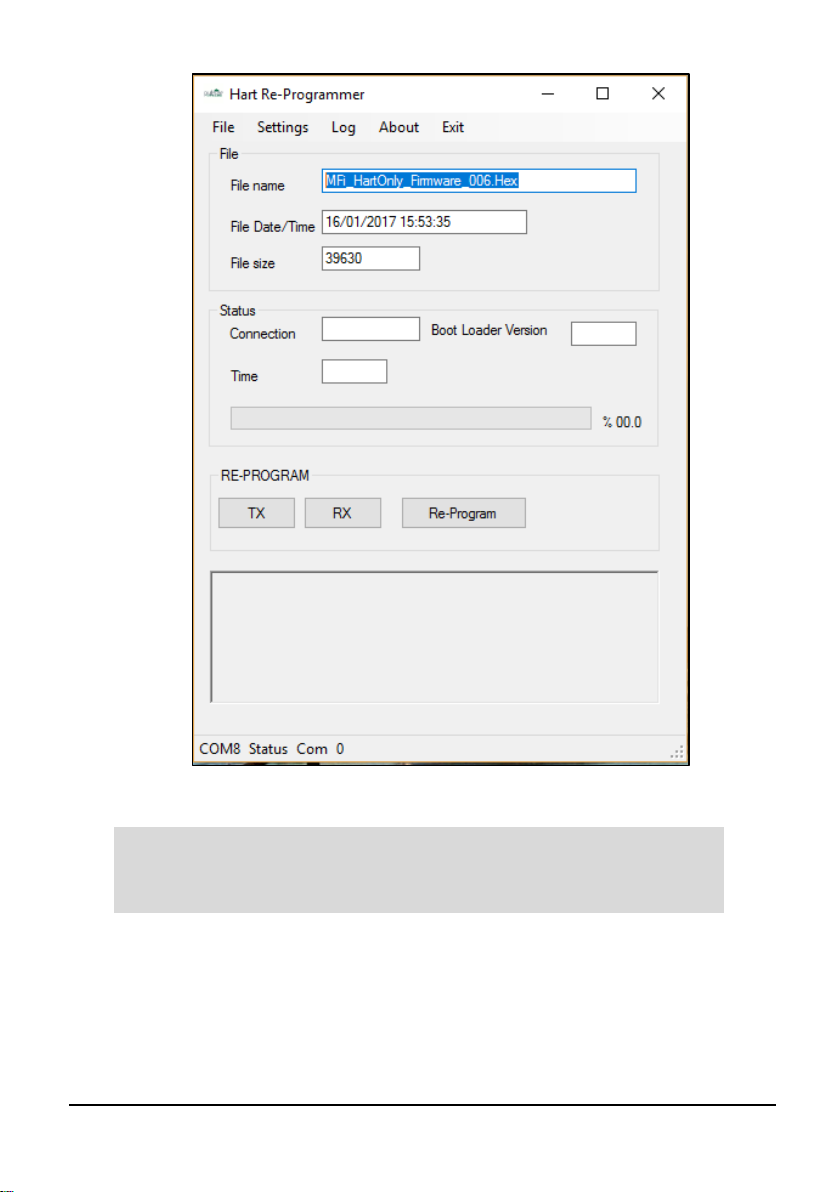
MicroFlow-i HART Firmware Upgrade
1. Please ensure that the sensor is connected to a PC via the HART modem.
Prior to reprogramming, you will need the HART firmware file, and the
COM port number of the modem.
2. Establish a connection to the sensor.
3. You will require Service access to Run HART Bootloader Control.
4. Select Tools > Run HART Bootloader Control, which will then open the
Bootloader control interface window as seen in Fig.11.
5. Once connected click File’, and choose the firmware file you are using to
upgrade the sensor.
6. Click ‘Re-Program’, turn the sensor off and on again when prompted to do
so by the Bootloader control and then wait for the process to finish.
7. When the ‘Program File OK now rebooting’ message is displayed, you can
close the HART Bootloader and reconnect to the PC software.
8. Select the ‘Search’ button on the software, and the sensor will reconnect to
MicroFlow-i HART PC with the new HART firmware installed.
Page 53
Page 47
Important Information
Do not switch off supply to the unit or close the software down
during the firmware upgrade.
Fig.11
Page 54

Page 48
Chapter 7 Troubleshooting
This section describes many common symptoms, with suggestions as to what to
do to resolve them.
Symptom
What to Do
Current velocity reads zero,
but you know that there is flow
movement.
Ensure that the sensor is mounted
correctly in accordance with Chapter
2.
Current velocity reading is
higher/lower than known
movement of flow.
Check that the sensor is mounted
correctly. Adjust the Gain (P102) or
Damping (P109) parameters to obtain
correct measurements.
Unable to connect to
MicroFlow-i HART PC.
Check that wiring to the modem is
correct. Close MicroFlow-i HART
PC software, cycle power on the
sensor and re-open the software.
Ensure that the correct Com port has
been set and retry connection.
Sensor remains at a high mA
out reading (20mA)
Ensure that Simulation mode (P288) is
set to 0 = Off
Ensure that ‘Resume mA’ has been
selected if in Run mode.
Important Information
If you experience any issues with our equipment, then please contact
your local Pulsar Distributor for assistance.
Page 55

Page 49
Chapter 8 Parameter record
Device Information Parameters
Processing Parameters
Parameter Details
Entered Values
No.
Description
Default
1 2 3 4 5
P240
&
P241
Serial No.
Read Only
P261
Firmware ID
Read Only
P262
Hardware ID
Read Only
Parameter Details
Entered Values
No.
Description
Default
1 2 3 4 5
P102
Gain
120 P104
Quick Resp Damp Factor
800
P108
Cal Factor
100
P109
High/Main damping
0 P113
Step response
0 = Off
P115
Low damping persist
2
P116
High damping persist
1 P117
No signal persist
2
P118
Signal present persist
2
P120
Minimum Flow cut off
150 (mm/s)
P125
Response
0 = Slow
P152
Multi Cal point 1 at 0.2 m/s
100
P153
Multi Cal point 2 at 0.4 m/s
100 P154
Multi Cal point 3 at 0.8 m/s
100
P155
Multi Cal point 4 at 1.5 m/s
100
P156
Multi Cal point 5 at 3.0 m/s
100 P157
Multi Cal point 6 at 5.0 m/s
100
P158
Multi Cal mode On/Off
0 = Off
P834
Low velocity for mA Span
0
P835
High velocity for mA Span
6
Page 56

Page 50
Chapter 9 Disposal
Incorrect disposal can cause adverse effects to the environment.
Dispose of the device components and packaging material in accordance with regional
environmental regulations including regulations for electrical \ electronic products.
Transducers
Remove power, disconnect the Transducer, cut off the electrical cable and dispose of
cable and Transducer in accordance with regional environmental regulations for
electrical \ electronic products.
Controllers
Remove power, disconnect the Controller and remove battery (if fitted). Dispose of
Controller in accordance with regional environmental regulations for electrical \
electronic products.
Dispose of batteries in accordance with regional environmental regulations for
batteries.
EU WEEE Directive Logo
This symbol indicates the requirements of Directive 2012/19/EU regarding the
treatment and disposal of waste from electric and electronic equipment.
 Loading...