

Page 1

MBT9600
FOUR-WIRE MODEM
FOR
TELEPROTECTION APPLICATIONS
Instruction Manual
September 1997
DM44–VER01
Technologies, Inc.
4050 NW 121st Avenue
Coral Springs, FL 33065
1–800–785–7274
Printed September 1997
Page 2

Page 3

September 1997 i
e recommend that you become acquainted with the information in this manual before
installing your new MBT9600 Four-Wire Modem. Failure to do so may result in damage to the
modem or relay equipment, and may affect the equipment warranty.
PULSAR does not assume liability arising out of the application or use of any product or circuit
described herein. PULSAR r eserves the right to make c hanges to any products herein to improve
reliability, function or design. Specifications and information herein are subject to change
without notice. All possible contingencies which may arise during installation, operation, or
maintenance, and all details and variations of this equipment do not purport to be covered by
these instructions. If you desire further information regarding a particular installation,
operation, or maintenance of equipment, please contact your local Pulsar Technologies, Inc.
representative.
Copyright ©
By Pulsar Technologies, Inc.
Published 1997
ALL RIGHTS RESERVED
PULSAR does not convey any license under its patent rights nor the rights of others.
!
IMPORTANT
W
Page 4

Preface
Scope
This manual describes the functions and features of the MBT9600 Four-Wire Modem. It describes the
proper installation procedure for use with your SEL mirrored bit relay. It is intended primarily for use by
engineers and technicians involved in the installation, alignment, operation, and maintenance of mirrored
bit relays.
Equipment Identification
The modem’s catalog order number — MBT9600 — is displayed on the top and bottom of the unit.
Warranty
Our standard warranty extends for 24 months after shipment. For all repaired units or advance replacements, the standard warranty is 90 days or the remaining warranty time, whichever is longer. Damage
clearly caused by improper application, repair, or handling of the equipment will void the warranty.
Note: Tampering or removal of the MBT9600 cover will void the warranty.
Equipment Return & Repair Procedure
To return equipment for repair or replacement:
1. Call PULSAR at 1–800–785–7274.
2. Request an RMA number for proper authorization and credit.
3. Carefully pack the equipment you are returning.
Repair work is done at the factory. The MBT9600 contains no user serviceable parts. When
returning any equipment, pack it in the original shipping containers if possible. Be sure to use antistatic material when packing the equipment. Any damage due to improperly packed items will be
charged to the customer, even when under warranty.
4. Make sure you include your return address and the RMA number on the package.
5. Ship the package(s) to:
Pulsar Technologies, Inc.
RMA Department
4050 NW 121st Avenue
Coral Springs, FL 33065
ii September 1997
Technologies, Inc.
Page 5

FIGURES
Figure No. Page No.
1 MBT9600 Four-Wire Modem . . . . . . . . . . . . . . . . . . . . . . . . . . . . . . . . . . . . . . . . .1
2 MBT9600 Typical Application . . . . . . . . . . . . . . . . . . . . . . . . . . . . . . . . . . . . . . . .1
3 MBT9600 DB9 Male Connector Pin Assignments . . . . . . . . . . . . . . . . . . . . . . . . . .3
TABLES
Table No. Page No.
1 MBT9600 Performance Specifications . . . . . . . . . . . . . . . . . . . . . . . . . . . . . . . . . . .3
2 MBT9600 Dimensions . . . . . . . . . . . . . . . . . . . . . . . . . . . . . . . . . . . . . . . . . . . . . .3
3 MBT9600 Power Requirements . . . . . . . . . . . . . . . . . . . . . . . . . . . . . . . . . . . . . . . .3
4 MBT9600 Audio Specifications . . . . . . . . . . . . . . . . . . . . . . . . . . . . . . . . . . . . . . . .4
5 MBT9600 Environmental Specifications . . . . . . . . . . . . . . . . . . . . . . . . . . . . . . . . .4
6 MBT9600 Connector Specifications . . . . . . . . . . . . . . . . . . . . . . . . . . . . . . . . . . . .4
September 1997 iii
MBT9600 Four-Wire Modem for Teleprotection Applications
Page 6

Technologies, Inc.
iv September 1997
Technologies, Inc.
Trademarks
All terms mentioned in this manual that are known to be trademarks or service marks are listed
below. In addition, terms suspected of being trademarks or service marks have been appropriately
capitalized. Pulsar Technologies, Inc. cannot attest to the accuracy of this information. Use of a term
in this book should not be regarded as affecting the validity of any trademark or service mark.
SEL is a registered trademark of Schweitzer Engineering Laboratories, Inc.
Page 7

Description
The MBT9600 is a high performance
four-wire modem designed for use with
Schweitzer Engineering Laboratories,
Inc. protective relays using "mirrored
bits" relay-to-relay logic communications. These relays use 4800 or 9600 bps
asynchronous communications as an
integral part of mirrored bit logic
communications for protection, monitoring, and control.
The MBT9600 provides the following
features and benefits:
• Compact size lets you mount it
directly onto the relay’s DB-9
(female) connector
• Powered by your serial port; no
external power supply is required
• Auto configuring; no user setup
required
• Fast retrain times (typically less
than 1 second)
• Low absolute data delays (see
Table 1)
MBT9600 Four-Wire Modem
September 1997 Page 1
Figure 2. MBT9600 Typical Application.
Figure 1. MBT9600 Four-Wire Modem.
Page 8

Application
As noted previously, the MBT9600 is
designed for use with SEL protective
relays using "mirrored bits" relay-torelay logic communications. Figure 2
shows a typical application.
The MBT9600 meets or exceeds all
applicable ANSI, IEEE, and IEC
standards.
Application specific features set the
MBT9600 apart from conventional highspeed modems. Conventional modems
typically have retrain times in excess of
15 seconds and absolute data delays in
excess of 25 milliseconds. These critical
parameters make conventional modems
unusable for pilot relaying applications.
The MBT9600’s compact size and ease of installation make it an ideal low-cost alternative to
conventional audio tone teleprotection systems.
The circuitry is ideally suited for use over private
networks such as conventional voice channels
over analog microwave.
Installation
These installation instructions tell you how to
install the MBT9600 for use with an SEL mirrored
bit relay and a microwave voice channel.
Hardware Installation/Connections
To install the MBT9600, complete the following
four steps:
1. Plug the MBT9600’s DB9 male connector
into Serial Port 2 on the rear of the relay
and tighten the retention screws finger
tight.
2. Connect the two “transmit,” or output,
wires from the voice channel device to the
“RX” terminals on the MBT9600 using
twisted, shielded pair cables.
3. Connect the two “receive,” or input, wires
from the voice channel device to the “TX”
terminals on the MBT9600 using twisted,
shielded pair cables.
4. Connect one end of a ground wire to the
“Gnd” terminal on the MBT9600 and the
other end to the “GND” terminal on the
rear of the relay. Also connect the cable
shield to the relay’s GND terminal. ALL
OF THESE GROUNDS MUST BE
CONNECTED BEFORE USE.
Note: Connect the cable shield to ground
only at one end.
5. Once the system is in full operation with
the communications path established,,
Target 20 of the SEL 321 will read “ROK”
indicating that the mirrored bits are
working properly.
The MBT9600 is now ready for operation.
Page 2 September 1997
Technologies, Inc.
Figure 3. MBT9600 DB9 Male Connector Pin Assignments.
Page 9
Ordering Information
The code for ordering the MBT9600 four-wire
modem is MBT9600, as displayed on the top and
bottom of the unit.
Specifications
The MBT9600’s technical specifications are
shown in Tables 1–6.
September 1997 Page 3
MBT9600 Four-Wire Modem for Teleprotection Applications
Data Rates 9600 or 4800 bps
Absolute delay* <12 ms @ 9600 bps;
<16 ms @ 4800 bps
Retrain Time Typically < 1 Second
Table 1. MBT9600 Performance Specifications.
Width .75" (1.90 cm)
Length 3.2" (8.13 cm) Projection mount
Height 1.25" (3.18 cm)
Table 2. MBT9600 Dimensions.
Source Pin 1 of the DB 9 connector
Current <125 milliamps
V oltage +5 Vdc
Table 3. MBT9600 Power Requirements.
*Absolute delay is the time span from when a bit first enters a modem until it exits the adjacent
modem.This time is exclusive of any communications system propagation delays.
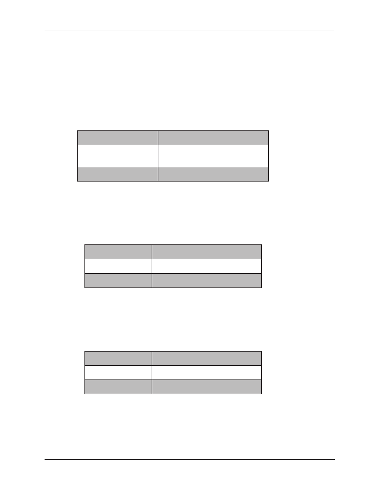
Page 10

SEL Mirrored Bit Relay DB9 Male
Microwave Voice Channel Screw-type (5-position)
compression terminal block,
accepting up to 18 AWG
wire
Table 6. MBT9600 Connector Specifications.
Temperature Range –40 to +85° C
EMI IEEE C37.90.2 /
IEC 1000-2-2
Dielectric ANSI C37.90 & C37.90.1 /
IEC 1000-4-4 & IEC 255-22-1
ESD IEC 1000-4-2
Table 5. MBT9600 Environmental Specifications.
Page 4 September 1997
Technologies, Inc.
Impedance 600 Ohms
Transmit Level –9* dBm
Receive Level –9* to –30 dBm
Minimum SNR 27 dB @ 9600 bps;
16 dB @ 4800 bps
Audio Bandwidth 300–3400 Hz (4-wire circuit)
Conditioning C4 conditioning is required
for leased circuits.
Table 4. MBT9600 Audio Specifications.
*Touch tone levels only
 Loading...