

Page 1
27216 - Masterpiece Replay 216
1U x 19" Rack Mounting Format
Your PULSAR Replay 216 is capable of controlling up to 512
DMX slots (channels) of lighting or effects. It will faithfully
reproduce any "shows" that have been programmed on a
Pulsar Masterpiece 48, 108 or 216 controller and transferred
to the Replay 216 via a memory card. A Masterpiece Screen
Driver and Monitor may be connected to the Replay 216 to
display a bar graph of the PMX channel levels and give details
of the contents of the pre-programmed Environments and
Environment Chases.
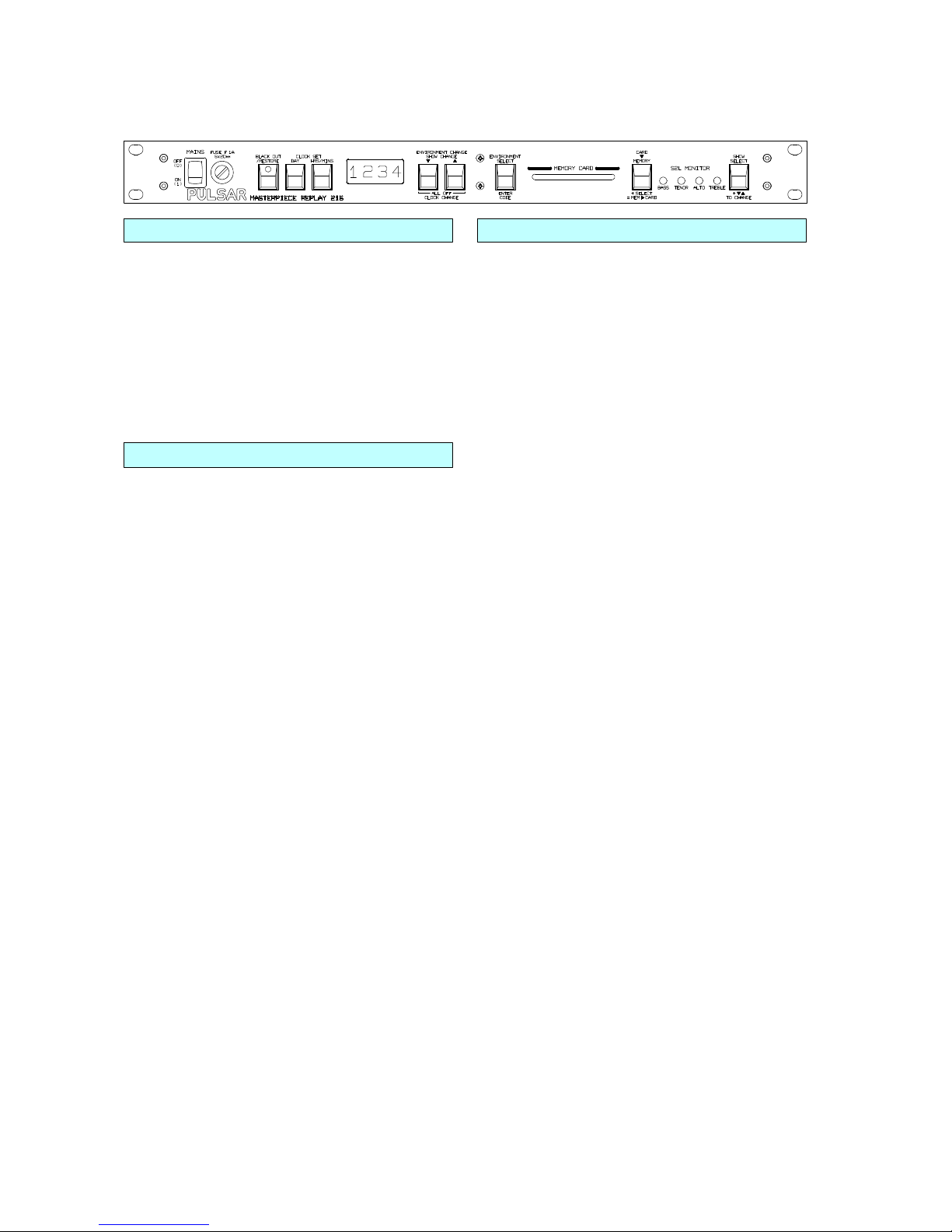
FRONT PANEL
MAINS ON/OFF SWITCH - Switches the mains On or Off!
The contents of the Replay Unit's Memory is maintained by a
rechargeable battery so it will start up in the same state as it
was at switch off except that all chases start from step one. At
switch on the Software Version is shown in the display - e.g.
No.2.2, followed by the current Show No. from 1-8 e.g. "Sho.1".
Software upgrades will be available free of charge from time to
time so please keep in touch.
FUSE - please see "Fuses and Precautions" overleaf.
BLACKOUT / RESTORE - When Blackout is selected, the
switch LED is lit and the channel outputs go to zero. This
switch toggles between Blackout and Restore.
THE 4 DIGIT DISPLAY - This shows words and numbers
keeping you informed of various events and functions, e.g.
Memory Card battery voltage or which Environment or
Environment Chase is selected - either from the front panel,
the Remote Control Socket or by MIDI.
CLOCK SET - It is hoped to implement this function in a
future software upgrade. It is intended that a new type of
Environment Chase will be provided whose steps are
controlled by Clock Time. Pressing the Day or the Hrs/Mins
button will display the clock. To adjust the clock it will be
necessary to hold one of these buttons down and use the
Clock Change Up or Down buttons to advance or retard the
clock.
ENVIRONMENT CHANGE - The s UP, t DOWN and
SELECT keys allow you to select Environments and
Environment Chases (E/EC) from the front panel. When you
press Up or Down the display EITHER shows the last E/EC
selected if something else was in the display OR steps up or
down to the next accessible E/EC. The Up and Down keys
are repeat keys and may be held down to scan round the
accessible E/ECs quickly. Having reached the desired E/EC,
press Select. The display shimmers until you press Select. If
you do not press Select within 10 seconds, the display will
drop back to the previously selected E/EC and become steady
again. While the Select key is pressed the display shows On /
Off / Flash depending upon the state of the Keyboard Action
chosen when the program was made Latch / Flash / Swap / Solo (AB crossfade mode is not
appropriate). When the Select key is released, the display
shows the E/EC just selected or changed.
ENVIRONMENT SELECT - pressed without first pressing
the Up or Down keys EITHER shows the last E/EC selected if
something else was in the display OR will toggle the last
selected E/EC if the Keyboard Action is in Latch OR will Flash
the last selected E/EC if the Keyboard Action is in Flash.
Other uses - see Up and Down section and Memory to Card
section.
SHOW SELECT - pressed on its own displays the current
Show No. from 1-8 e.g. "Sho.1".
SHOW CHANGE - While pressing the SHOW SELECT key
use the s UP and t DOWN keys to choose the next show.
When Show Select is released the Replay 216 changes to the
selected show.
RELEASE ALL / ALL OFF (for trouble shooting) - is
achieved by pressing the Up and Down keys together. After
keeping them pressed for 2 seconds the Release All Sliders
function is performed and the number released is shown. This
number would normally be 0 unless the memory has been
corrupted. After a further 1 second the All Off function is
performed, switching everything off and giving you a clean
slate from which to select your chosen E/EC. Note: If a slider
was deliberately engaged to control a Channel, Scene, Chase
or other level, and Set User Access Levels had been used to
lock this slider away, Release All will not disengage it.
MEMORY CARD SLOT - The Memory Card contains all
the information needed by the Replay 216 to reproduce a
lightshow programmed on a Masterpiece 48, 108 or 216.
When a Card is correctly inserted, the 4 digit display will
indicate the Card's battery voltage. Battery Life is about 5
years. The Replay 216's internal memory is maintained by a
rechargeable battery which automatically charges when the
Replay Unit is in use. Keep your Memory Card in a secure
place as a backup.
CARD TO MEMORY - Insert your Memory Card. Press the
Card to Memory key. The display indicates which Memory
Card Source Show (9-16) will be transferred to the Current
Show (1-8). E.g. "Sho.9 to Sho.1". To change the Source
Show use Show Change as described above. The Source
Show may even be another Internal Show (1-8). This provides
a "copy Show to Show" function. When you have selected the
required Source Show, press the Enter Code key to start the
transfer, or press Card to Memory again to cancel. To load
into a different Destination Show (1-8) you must first make this
the Current Show - see Show Change above.
MEMORY TO CARD - It would be normal to work from your
security backup memory card rather than the contents of the
Replay Unit's Memory, however, should you need to do
Memory to Card, proceed as follows: Insert your Card, then,
while keeping the Card to Memory button pressed, press
Select to change to Memory to Card. The display indicates
the Current Show (1-8) will be transferred to Card Show (9-16).
E.g. "Sho.1 to Sho.9". To change the Destination Show use
Show Change as described above. The Destination Show
may even be another Internal Show (1-8). This provides a
"copy Show to Show" function. When you have selected the
required Destination Show, press the Enter Code key to start
the transfer, or press Card to Memory again to cancel. To
load from a different Source Show (1-8) you must first make
this the Current Show - see Show Change above.
MASTERPIECE REPLAY 216
FRONT PANEL cont.SPECIFICATION
Page 2
SOUND-TO-LIGHT MONITOR LEDS - These LEDs
monitor the 4 Sound-to-Light bands. Pulsar's top of the range
Modulator Sound-to-Light circuits are built into every member
of the Masterpiece family. The Masterpieces have 3 zones of
4 bands - 2 modulating zones and 1 digital zone, each
patchable at any level over the 48/108/216 channels. The
Sound-to-Light circuits are fully automatic with a master
Automatic Volume Control (AVC) to adjust for overall changes
in the music volume and one AVC circuit for each band to
adjust for changes in the balance between, for example, the
bass and the treble. Optimum Sound-to-Light performance is
thus ensured at all times.
PROGRAMMING TIP 1 - Rather than stepping through all 48
Environments and 6 Environment Chases, the Up and Down
keys only stop on the accessible Keyboard keys and
Keyboards. So, for example, if you only have 2 ECs and 6 E's
programmed on Keyboard E3, use Set User Access Levels to
disable E1 and E2 Keyboards and unused E3 Keyboard keys.
PROGRAMMING TIP 2 - Swap 3 is an ideal Keyboard Action
to use with the Replay Unit. Keys 1-5 of a 6 way, Swap 3
Keyboard can contain effects to swap between while key 6 can
be a blackout E/EC. The 3 Keyboards may be configured as
up to 9 Swap 3 Keyboards.
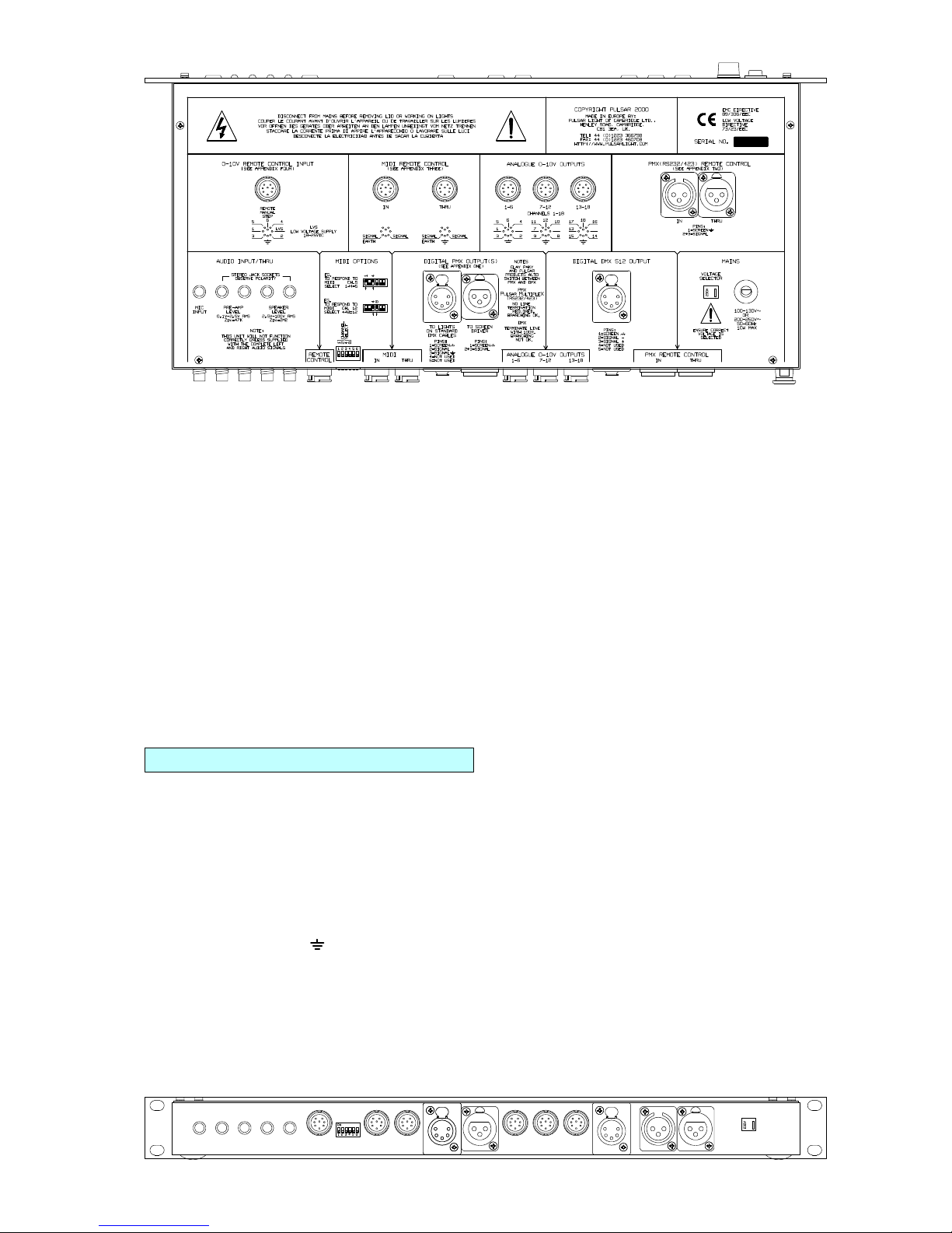
BACK PANEL - CONNECTIONS
MAINS SUPPLY - 100-130 or 200-250 VAC, 50-60 Hz,
6 Watts. We recommend the use of a Residual Current Circuit
Breaker.
VOLTAGE SELECTOR - Ensure the correct voltage range -
115V / 230V, is selected before switching on!
MAINS CABLE - the mains cable should be fitted with a
suitably approved and rated plug. Note: in some countries it is
a requirement that such a plug be fitted by a qualified
electrician.
CABLE COLOURS
Green/Yellow = Earth / Ground
Brown = Live / Phase / Hot
Blue = Neutral
WARNING - THIS APPLIANCE MUST BE EARTHED
AUDIO INPUT SOCKETS - The Replay Unit is fitted with
standard 1/4" Jack sockets for audio connection. One mono
microphone input socket is provided, two stereo line level (0.1V
- 2.5V RMS) sockets (in / thru) and two speaker level (2.5V -
100V RMS) sockets (in / thru). Please note, when feeding a
signal from a stereo system, both left and right audio signals
must be supplied for the Replay Unit to produce faithful
Sound-to-Light.
0-10V REMOTE CONTROL - An 8 pin DIN socket is
provided for input from a Remote Controller - e.g. a
Masterpiece Outstation or a Master Masterpiece. Please
see Appendix Four for full details.
MIDI REMOTE CONTROL IN / THRU - 2 DIN sockets are
provided for remote control by a standard MIDI signal. Please
see Appendix Three for full details.
PMX REMOTE CONTROL IN / THRU - A 3 pin XLR plug
and socket are provided for remote control from a computer by
RS232, using our PMX protocol. Please see Appendix Two
for full details.
DIGITAL PMX OUTPUT(S) - Two XLR sockets are
provided for the PMX (Pulsar MultipleX) digital outputs. Use
the 3 pin socket (RS232) for short distances - e.g. to a
Masterpiece Screen Driver, and the 5 pin socket (RS423) for
any distance. All 216 channels are transmitted. Products
capable of receiving PMX include Clay Paky Intelligent
Spotlights, Pulsar Datapaks, Pulsar Universal Interfaces
(to convert PMX to 0-10V analogue), etc. As well as Channel
Levels, the PMX data stream contains the key press
information required to drive a Masterpiece Screen Driver.
Please see Appendix One for full details of the PMX protocol.
The pin connections of the XLR sockets are:
3 PIN SOCKET 5 PIN SOCKET
Pin 1 = Screen - Chassis Earth Pin 1 = Screen - Chassis Earth
Pin 2 & 3 = Signal Pin 2 = Signal
Pin 3 = Signal earth
Pins 4&5 = not used
MASTERPIECE SCREEN DRIVER SETUP - the Screen
Driver does not know whether your Replay Unit's program
was made on a Masterpiece 48, 108 or 216. Therefore please
use the DIL switches on the back of the Screen Driver to
select Masterpiece 48, 108 or 216 screen formats.
ANALOGUE 0-10V OUTPUTS - The first 18 of the 216
channels are available here as 0-10V analogue signals. There
are 3 DIN sockets, 6 channels each. The pin connections are:
Pin 1 - Not Used, 2 - Earth, 3-8 - Channels 1-6, 7-12 & 13-18,
as printed on the Replay Unit lid. The outputs are via isolating
diodes so they may feed the same equipment as other
controllers - the highest taking priority.
Page 3

DIGITAL DMX 512 OUTPUT - 512 DMX slots or 216 PMX
channels are transmitted. If the patch is off (patch on/off
information is transferred with card data), the 216 PMX channel
levels are transmitted as DMX slots. If the patch is on, then
512 DMX slots are transmitted using the PMX to DMX patch
map information transferred with the card. DMX slots are
transmitted in a serial digital format complying with the
DMX512 and DMX512/1990 standards.
The pin connections are:
Pin 1 = Screen - Chassis Earth
Pin 2 = Signal Pin 3 = Signal +
Pins 4&5 = not used
Please use twin core screened cable and ensure that the end
of the DMX line is terminated with a resistor of 100-120 ohms
between Signal + and Signal -. A DMX line must not be split or
branched without the use of a purpose built splitter unit. A
PMX (Pulsar MultipleX) line does not need terminating and can
be branched or split.
FUSES AND PRECAUTIONS
MAINS FUSE - The Mains Fuse is mounted on the front
panel of the Replay Unit. The fuse is a F 1A L 5x20mm Glass
fuse. Do NOT use any other type of fuse. Failure indicates an
internal fault and servicing by a qualified engineer will be
required.
INSTALLATION AND VENTILATION - The Replay Unit
consumes very little power, therefore ventilation around the
unit is not required, and several units may be stacked together.
OTHER INFORMATION
MAINS CABLE REPLACEMENT - This
modification should only be carried out by suitably
skilled and competent persons.
Important - the earth wire must be longer than the live and
neutral wires so that the earth will always be the last wire to
come off if the cable is pulled from the unit. Ensure the outer
sheath covering the live and neutral wires is within 15mm of
the live and neutral tags on the PCB.
AUDIO INPUTS - These are not earthed directly within the
unit but through a resistor, this eliminates earth loops and
hence hum and interference on your sound equipment.
PORTABLE APPLIANCE TESTING - The Replay Unit
may be safely Earth Bond and Insulation (500V) tested.
STANDARDS - The Replay Unit complies with the following
International and National Standards:
Electrical Safety - IEC65, EN60065, BS415
EMC - EN50081-1, EN55022, EN50082-1
Rack Mounting - IEC297
Index of Protection - IP30
Marking Directive 93/68/EEC - The Replay Unit
meets both the EMC Directive 89/336/EEC and
the Low Voltage Directive 73/23/EEC.
GUARANTEE - 12 Months from the original date of
purchase. The guarantee is limited to parts and labour. The
guarantee is void if the unit is misused, repairs are performed
by unauthorised persons, or the incorrect fuse has been used.
In the unlikely event of a fault occurring, do not use without
repair. Return the unit, with a description of the fault, to your
supplier or direct to Pulsar for immediate attention.
COMPATIBLE PRODUCTS
The following products have been designed to work with and
complement the Pulsar Replay Unit. Please contact us to
receive further details of these superb products!
Masterpiece, Spares and Extras
Product No. Controller/Accessory
23000 Masterpiece 48 Control Desk.
24000 Masterpiece 108 Control Desk.
20216 Masterpiece 216 Control Desk.
23900 Masterpiece Screen Driver.
24301.1 Masterpiece Monitor for screen Driver.
22202 Masterpiece RAM Card.
24001SP Latest Masterpiece 108 Upgrade software.
24007SP Latest Masterpiece 216 Upgrade software.
24008SP Latest Replay 216 Upgrade software.
29805ST 6 Way Masterpiece Outstation Status.
29800AA 12 Way Masterpiece Outstation Basic.
29800ST 12 Way Masterpiece Outstation Status.
Digital Reception
Product No. Datapak
29900.3/29901.3 12 Ch Dimming/Switching Datapaks 5/10A
29902.3/29903.3 18 Ch Dimming/Switching Datapaks 5/10A
29950 /29951 12 Ch Switching Datapaks 5/10A
29952 /29953 18 Ch Switching Datapaks 5/10A
29904.3 9 Ch Dimming/Switching Datapak 20A
Digital Reception
Product No. Interface
27770 6 Ch PMX/DMX 0-10V Interface
27300/27350 1U 36/18 Ch Universal Interface
27400 18 Channel Switching Interface
Analogue Control
Product No. Dimmer/Switching Packs
27700/30/50 3 Channel Minipaks.
27740/60 4 Channel Minipaks.
29209 SW6000 1U 1Ph Switch Pack 6x IEC
25802AA 6 x 5A 2U 1Ph Switch Pack H/W
25902AA 6 x 5A 2U 1Ph Dimmer Pack H/W
25452AA 8 x 5A 2U 1Ph Dimmer Pack H/W
25802ST/702ST 6 x 5/10A2U 1-3Ph Switch Pack H/W
25902ST/802ST 6 x 5/10A2U 1-3Ph Dimmer Pack H/W
21112-9ST 6 x 10A 4U 1-3Ph Dimmer Packs with skts
28806 6 Ch.PMX/DMX to 0-10V Kit for Rackpaks
Strobe Lighting
Product No. Strobe.
21300 Super/Maxi Strobe.
20700.1/.2 Jumbo Strobe / Jumbo Strobe 100-130V.
28600 Monster Strobe.
27800 Demon Strobe.
Lanterns
Clay Paky Intelligent Spotlights.
The comprehensive range of Pulsar stage, rock and effects
lanterns, and PAR36 and PAR46 Pinspots.
19" Racks and Accessories
4U, 8U and 12U Rack Cabinets & Doors.
Blanking & Vent Panels are also available.
MASTERPIECE REPLAY 216 cont.
DIMENSIONS AND WEIGHTS
Code Unit Width Height Depth Weight
mm. mm. mm. kgs.
27216 Masterpiece Replay 216 483.0 43.6 206.0 3.8
Console Cut Out 450.0 40.0 265.0 Fixing Holes 465.6 31.8 - -
 Loading...