

Page 1

MASTERPIECE
MANUAL
Masterpiece 216
Masterpiece 108
Masterpiece 48
Page 2

Masterpiece
Software
Upgrades
NEW IN SOFTWARE VERSION "MASTERPIECE MAIN No.1.i" - 12-03-91
The Remote Control DIN Socket is operational - see appendix 4. This allows great scope for expanding the system
- for example a number of Masterpieces can be used to control different sections of equipment under the control of a
"master" Masterpiece.
NEW IN SOFTWARE VERSION "MASTERPIECE MAIN No.1.1" - 09-04-91
Improvements in the operation of 1 shot chases.
NEW IN SOFTWARE VERSION "MASTERPIECE MAIN No.1.2" - 09-05-91
Security Code - rather than any 4 key presses on the Keyboard, the correct security code is now required for
Memory to Card, Card to Memory, Swap Memory and Card (both keys together) and now for Set User Access Levels.
The security code has a fixed value of: 12, 6, 7, 1.
If a Keyboard key is not pressed within 5 seconds, the program mode required is cancelled and the word "CNCL" is
displayed. The word "FAIL" is displayed if the wrong code is entered.
Set User Access Levels (SUAL) - to enable or disable any slider or pad. For example, to allow the operator the use
of an Environment Keyboard of pre-programmed effects but disable everything else to prevent accidental corruption of
the program or changes to the show.
Operation: press the SUAL key, enter the code, after the correct code the word "SUAL" is displayed, now all the
LEDs show whether a pad or slider is currently accessible or not. Touch a pad to change its accessibility - the LED
changes state and the display shows "ON" / "OFF". For sliders, move the slider to change its accessibility - if the
slider is over 50% its LED is on and it is accessible, at less than 50% its LED is off and the slider is disabled. Press
the SUAL pad again to finish. The word "DONE" is displayed or "CNCL" if no changes have been made.
When a pad or slider is disabled, its level before entry to SUAL is permanently maintained.
Touching a disabled pad makes the SUAL LED flash and puts the word "SUAL" in the display.
Moving a disabled slider also makes the SUAL LED flash but puts the slider's level in the display to "view" it.
SUAL mode may be used during a show without affecting the performance.
Parking Sliders at 0 no longer engages them to zero level Channels/Keyboard Masters.
NEW IN SOFTWARE VERSION "MASTERPIECE MAIN No.1.3" - 17-05-91
Concurrent Programming - besides SUAL, the other programming functions - Save Output To Scene, Program
Chase Sequence and Save Environment of Channels Scenes and Chases all run concurrently with the light show
without affecting it.
Release All - (Release + Slider Action pads together), is now available to release any slider from having overriding
control of an output Channel Level on any of the 6 Output Select pages or of a KeyBoard Master level on any of the 18
KeyBoards.
Continued...
Paul F. Mardon, Technical Director, 28-10-98
File: MPN.Sam PAGE 1 of 11
Page 3

Masterpiece
Software
Upgrades
NEW IN SOFTWARE VERSION "MASTERPIECE MAIN No.1.3" - 17-05-91 continued
Automatic Release and Replace - when you Save Output To Scene (SOTS) or Save Environment of Channels,
Scenes and Chases (SESC), all sliders are RELEASED and all KeyBoard pads are turned off. The Scene or
Environment which you have just saved is switched on to REPLACE them.
Should you NOT want this facility to operate, hold your finger on SOTS or SESC until AFTER you have removed your
finger from the KeyBoard pad.
NEW IN SOFTWARE VERSION "MASTERPIECE MAIN No.1.4" - 01-06-91
Environment Chases - The 6 Environment Chases are now available with Auto and Manual stepping. Each one may
have up to 124 steps. They are programmed in the same way as Scene Chases except that after pressing "Program
Chase Sequence", you select one of the 6 Environment Chases on Environment Keyboard No.3, Keyboard pads 1-6
and then the steps you enter are Environments rather than Scenes. Forward and Reverse Manual Step pads can be
used for editing just the same - see Page 5.6 of the Manual.
The Black Out key "b.O." may be used during Scene or Environment Chase programming to enter a blank step - it
too blinks to indicate availability if no key is pressed within 5 seconds.
Fine details:
Automatic Release and Replace no longer forces the Scene or Environment KB into latch but leaves the choice of
Keyboard Action to the user.
Improved blinking of KB LEDs when engaged to KeyBoard Master sliders.
The accessibility of the Memory to Card pad (only) is not updated during Card to Memory transfer which would
inevitably make it accessible.
NEW IN SOFTWARE VERSION "MASTERPIECE MAIN No.1.5" - 10-07-91
Environment Chases - The 6 Environment Chases are now also operational in Real Time. Pressing the "Chase
Step Source" pad OR the "Record Environment Chase in Real Time/Step Times" pad when "Which Chase" is an
Environment Chase, will step through: Step Times, Real Time, Auto and Manual (Bass and Treble are not
appropriate).
There are two methods of recording the times for each step in Program Chase Sequence (PCS) for Environment
Chases:
1. Real Time. Normally used for recording and replaying a show. Perform your show, pressing the Environments
you require on cue. The Masterpiece records the moment when you entered each step, to a resolution of 0.02
seconds, ready to recreate your show on playback.
2. Step Times. Normally used to enter the longer step times needed for environmental control. After you enter
the Environment for each step of the chase, the step number is displayed for 2 seconds, then you can use the
Joy Stick to view (X axis) or adjust the time (Y axis) from this step to the next one. The maximum time per step
is 3 days, 21 hours, 12 mins, 24.30 secs. There are 124 steps available - over 15 months are possible before
repeating!
Continued...
Paul F. Mardon, Technical Director, 28-10-98
File: MPN.Sam PAGE 2 of 11
Page 4

Masterpiece
Software
Upgrades
NEW IN SOFTWARE VERSION "MASTERPIECE MAIN No.1.5" - 10-07-91 continued
Editing times - two methods - regardless of whether the Environment chase was made in "Real Time" or "Step Time"
mode:
1. Re-enter PCS in Real Time mode, press Forward Manual Step on each cue of your show. The timings of your
presses replace the existing times.
2. Re-enter PCS in Step Times mode, use Forward Manual Step to see the Environment for that step when pressed,
the Step Number for two seconds when released, then you have use of the Joy Stick to view (X axis) and change
the times (Y axis).
It is not possible to see all 9 digits of the step time at once so Joy Stick X allows you to window through the time,
alternately displaying part of d.hh. ' '. " ".th and the step time figures.
d. h h. ' '. " ". t h Time display - use Joy Stick X axis to window through the step time,
d h h m m s s t h use Joy Stick Y axis to change the time.
a o o i i e e e u
y u u n n c c n n When running an Environment Chase, "Step Times" and "Real Time" work
s r r u u o o t d identically and like "Manual", they use the Slope slider to set the fade in and out
s s t t n n h r times.
e e d d s e The start time for a real time Environment Chase is the moment when it is
s s s s d switched on, either by pressing the pad or by switching on the mains supply to
t the unit where the required Environment Chase was running at switch off.
h
s All chases start at step 1 at switch on.
To perform a pre-recorded show, start the music, if your show starts on the first beat for example, hit the Environment
Chase pad in time with it, the rest is automatic.
To control the lighting of a museum for example, one could power the Masterpiece from a time clock which switches
on at 8.00am, then the steps of the Environment Chase control the lighting for the rest of the day.
The Memory Card's Battery Voltage is displayed when a Card is inserted. The words "Good" (>2.75v), "FAIR"
(2.5-2.75v) or "Lo" (<2.5v) are also displayed. The display continues to monitor the voltage until any other key is
pressed or slider moved. Memory to Card and Card to Memory are not allowed if the battery voltage is low - "FAil" is
displayed. This guards against: no Card, no battery, battery in back to front and a flat battery. (Should the
transferred data not verify correctly, "FAIL" is displayed).
Fine details: • Pressing Forward or Reverse Manual Step before the fade is finished no longer loses a step - the
step forces the completion of the fade. • The software will now read correctly from the newly available "Write
Protected" Memory Cards while their protection is switched on.
NEW IN SOFTWARE VERSION "MASTERPIECE MAIN No.1.6" - 06-09-91
Improvements to the operation of the Remote Control Socket:
The response time of the RC socket is now extremely fast - important when the unit is a slave in a multiple
Masterpiece system.
The RC signal can now drive Environment Keyboards which are in Flash and Solo modes as well as Latch and
Swap modes.
The RC signal works correctly even if all the Keyboard pads have been made inaccessible.
It will not leave an inaccessible Keyboard selected but returns to the previous one after an input in this case.
Input codes 57-63 have been removed and are reserved for special functions.
So far just code 63 is in use and allows you to remotely transfer Card to Memory.
Also see Appendix Four of the Manual.
Paul F. Mardon, Technical Director, 28-10-98
File: MPN.Sam PAGE 3 of 11
Page 5

Masterpiece
Software
Upgrades
NEW IN SOFTWARE VERSION "MASTERPIECE MAIN No.1.6" - 06-09-91 continued
Selective Memory Transfer: After pressing Memory-to-Card, Card-to-Memory or both for Swap Memory and Card,
all the 18 Keyboard Select LEDs light up, allowing you to turn off any Keyboard you don't want to transfer. Do this
only if required and then enter the Security Code as usual. This allows the expert programmer to pick and mix parts
of various shows together to create a new one - eg. using the Scenes from one show with the Chases and
Environments of another.
The MIDI socket is now fully operational - BUT only if the DMX/MIDI EPROM in the Masterpiece is ALSO
upgraded to "DMX/MIDI V1.3". A MIDI signal selects the Masterpiece's Environments and Environment Chases - see
Appendix Three for full details.
"Use Scene Fade Times" key, previously not in use, now has the following effect:
LED on - Fade in the chase at switch on, LED off - Step in the chase with the first Scene/Environment at full -
sometimes needed for control of intelligent lighting.
NEW IN SOFTWARE VERSION "MASTERPIECE MAIN No.1.7" - 06-02-92.
Switching Sound-to-Light (S2L) on Zone 3. Useful for a dramatic effect or for producing a better result from
devices with significant response times such as PAR64 lamps, Pin Spots or Golden Scan stoppers. Zones 1 and 2
continue to have modulated S2L with the full range of dimming.
Treble & Bass Burst are now available for Scene Chases, providing a whole range of super effects. With the SPEED
control high, a burst of steps is produced for the duration of the beat. With the SPEED control low, a single step is
produced on the beat. The SLOPE control gives two options. With the SLOPE control >50%, the chase STEPS
from one step to the next. With the SLOPE control <50% the chase FADES from one step to the next - giving some
lovely effects at low SPEED settings - partial fades towards the next step during the beat followed by frozen
movement between beats.
Bass Bounce ("bASS") replaces Bounce/2 ("RRFF") for Treble Burst, Bass Burst and Auto scene chases providing
more super effects. Manual and all Environment Chases retain Bounce/2.
All Off - Release Sliders + Slider Action does "Release All sliders" but now if both keys are kept pressed for 3
seconds, all Scene, Chase and Environment keys are also turned off.
Two Security Codes - only the new "Programmer's Code" will now allow entry to Set User Access Levels. The
existing "Operator's Code" (12, 6, 7, 1) now only allows Card / Memory transfer.
The Forward & Reverse Manual Step keys show the Step Number, at finger off, of the Chase to which the Chase
Controls are engaged. This facility works in Treble, Bass and Auto as well as Manual.
The Masterpiece Screen Driver unit will be available from Q2 1992. This will be an optional add on unit to the
Masterpiece. Amongst other facilities, it provides:
On screen help in many languages by holding down a key for more than 0.5 seconds,
A User Text Area for each Output Select Page and Keyboard where you will be able to enter details of your
Channel Assignments, Scenes, Chases, Environments, etc. in full colour, using the Masterpiece keys for text
entry,
A Bar Graph display of the levels of the Output Channels.
Version No.1.7 of the Masterpiece software transmits all the key press and ASCII text information ready for the
Screen Driver unit. This is mixed in with the existing PMX (Pulsar MultipleX) data stream from the Masterpiece.
Paul F. Mardon, Technical Director, 28-10-98
File: MPN.Sam PAGE 4 of 11
Page 6

Masterpiece
Software
Upgrades
NEW IN SOFTWARE VERSION "MASTERPIECE MAIN No.1.7" - 06-02-92 - Continued
Two Security Codes - only the new code will now allow entry to Set User Access Levels.
The new Programmer's Code -
2, 3, 11, 10
is now required to enter Set User Access Levels. It also works for Card / Memory transfers.
The Operator's Code -
12, 6, 7, 1
is the same as before but now ONLY works for Card / Memory transfers.
* * * * * REMOVE THIS SHEET * * * * *
if you don't want the Lighting Operator to be able to change the User Access Levels.
Paul F. Mardon, Technical Director, 28-10-98
File: MPN.Sam PAGE 4a of 11
Page 7

Masterpiece
Software
Upgrades
NEW IN SOFTWARE VERSION "MASTERPIECE MAIN No.1.8" - 24-07-92.
From version No.1.8 two EPROMs are available:
"Masterpiece 108 MAIN No.1.8"
and
"Masterpiece 48 MAIN No.1.8"
Production of the Masterpiece 48 started in July 1992 using this software version from the beginning. All planned
features of the MP48 are available and working. However, as the MP48 can replay programs made on the MP108,
you may like to keep its software upgraded as more facilities become available on the MP108. BUT be sure in future
to specify whether you need software upgrades for the MP108 or the MP48.
Obviously the Masterpiece Manual is in a temporary phase so for the time being if you are a MP48 owner, you will find
references to facilities only available on the MP108 - please bear with us.
NEW FEATURES:
The MIDI input (MP108 only) can now respond to all 128 MIDI notes. In addition to giving control of the three
Environment Keyboards, Scene Keyboards 10 & 11 are accessed using notes 0-35 and Scene Chase Keyboard 3 by
notes 99-116. Please refer to the June 92 or later version of Appendix Three for full details.
Environment Chases can now be driven by Bass, eg. from a Click Track accompanying a music tape. On the
MP108 Real Time and Step Times are the same in playback leaving the fourth option available as Bass.
Chase Direction - the Bounce/1 mode "RFRF" has been replaced by Alternate "ALt". In ALt mode, each time a
chase is switched on it runs in the opposite direction. This allows you to produce a more varied and interesting light
show without extra programming. Should you still want to produce a Bounce, just enter the extra steps when
programming the chase sequence.
Flash - when the sliders are acting as Keyboard Masters and have control of the levels of Scenes, Chases or
Environments, the Keyboard keys are now able to flash them to full.
Card To Memory will not read from Masterpiece Screen Driver Cards.
Improvements to the operation of the LEDs in SUAL mode.
NEW IN SOFTWARE VERSION "MASTERPIECE MAIN N.1.85" - 20-06-93.
Remote Blackout (R.b.O.) by MIDI or Remote Control. A Blackout can now be forced remotely by MIDI or via the
Remote Control Socket as is sometimes required by Fire Authorities - see Appendix 3 and Appendix 4.
All Off can now be done from MIDI - note number 127.
Robust Operation. To prevent you having to make those panic midnight calls to the installer we have made the
following changes to make the software (we hope) virtually bomb proof provided you saved your work on a Card
Card to Memory is always accessible,
After Card to Memory the Grand Master is always 100%,
After Card to Memory the Output Select and Keyboard Select are changed to those stored in the Card,
Card to Memory still works even if the Masterpiece's memory has been corrupted (eg by loading from a partially
inserted card) or if so many things are switched on that the Watchdog Timer cuts in and all the LEDs are blinking
- commonly known as "Brain Overload".
Bug Fixes: • Switching the mains off and on in SUAL changed the chase keys' accessibility. • Environment
chases in MP108 said "S.t." when they should have said "bASS". • The MP48 Remote Control Socket didn't work
the Environment Chases correctly with certain Keyboard Actions.
Paul F. Mardon, Technical Director, 28-10-98
File: MPN.Sam PAGE 5 of 11
Page 8

Masterpiece
Software
Upgrades
NEW IN SOFTWARE VERSION "MASTERPIECE 108 MAIN No.1.9" - 28-09-93.
FADE IN and OUT TIMES. Although printed on the front panel as "SCENE FADE TIMES", the system has been
enhanced beyond that originally planned, to give Fade IN and OUT Times to SCENE CHASES as well as SCENES.
Environments and Environments Chases don't have Fade Times but of course the Scenes and Scene Chases they
contain can. Note: The Scenes within a Scene Chase can have fade times if required.
Overriding Global Control of all Fade In and Out Times is achieved by moving the IN and OUT sliders to engage
them (LEDs blinking) and choosing suitable Fade In and Out times. These slider values then operate for all Scene
and Scene Chase Fade In and Out times, overriding the individual fade times stored with them.
Cancelling Global Control of all Fade In and Fade Out Times. While pressing Release Sliders, move the IN
and/or OUT sliders to release them from having overriding control. The Fade In and/or Out times stored with each
Scene and Scene Chase now operate. Release All - Release Sliders & Slider Action together, also releases the IN
and OUT sliders.
Old Memory Cards. When loading a show from a Memory Card made with an earlier version of software:
All the Fade In and Out Times stored with the Scenes and Scene Chases are set to zero.
The IN and OUT sliders are set to zero and made inaccessible.
These ensure that your show will work with the 1.9 software exactly as it did before.
To Save a Scene's Fade Times the IN and/or OUT sliders need to be engaged (LEDs blinking) when you do "Save
Output To Scene" - otherwise the Scene's own existing values remain.
To Modify a Scene's Fade Times: switch on the Scene (on its own, and allow it to fade to full if it has a fade in
time), adjust the IN and/or OUT sliders to the required times, save the scene back to itself.
To Save/Modify Scene Chase Fade Times the IN and/or OUT sliders need to be engaged (LEDs blinking) and the
Controls Engaged LED needs to be on, when you do "Program Chase Sequence plus Select the Chase to be
programmed" - otherwise the Scene Chase's own existing values remain.
Seeing the stored fade times. When you switch a Scene or Scene Chase on or off, the display shows
(sequentially) the IN and OUT times, and for Scene Chases, the SPEED and SLOPE as well. Also, provided the IN
and/or OUT sliders are not engaged, their LEDs will be updated with these fade time values for a rough indication.
VIEW may be used to give an accurate read out - move the IN or OUT slider WHILE an Output Select or Keyboard
Select key is pressed.
Enhancements to the VIEW system. (The VIEW system puts useful information in the display. It is activated by
moving a Slider or pressing a Key WHILE an Output Select or Keyboard Select key is pressed. No levels or functions
are changed in the process.) New features:
While holding an Output Select key pressed, pressing a Keyboard key displays the Channel Number
(C. 1 - C.108) followed by the Channel's Level at finger off.
While holding a Scene Keyboard Select key pressed, pressing a Keyboard key displays (sequentially) the
Scene's Fade In and Out times.
While holding a Scene Chase Keyboard Select key pressed, pressing a Keyboard key displays the Scene
Chase's Fade In and Out Times, its Speed and its Slope and connects this chase to the chase controls
without having to switch it on or off. NB. For Manual chases and Real Time / Step Time Environment Chases,
the Slope is the crossfade time in seconds.
Tip - to see if any Scenes or Scene Chases have fade times, ensure the IN and OUT sliders are released, then,
WHILE pressing a Keyboard Select key, run your finger across the Keyboard watching the IN and OUT LEDs.
Remote Swap Memory and Card is now possible from MIDI and the Remote Control Socket. See Appendix Three
- Remote Control by MIDI and Appendix Four - Using the Remote Control Socket.
The Grand Master Level is now loaded from a Memory Card (when loading from old cards it is put to 100%).
Paul F. Mardon, Technical Director, 28-10-98
File: MPN.Sam PAGE 6 of 11
Page 9

Masterpiece
Software
Upgrades
NEW IN SOFTWARE VERSION "MASTERPIECE 108 MAIN No.2.0" - 15-07-94
54 KEYBOARDS! Select Latch + Swap and then press the "Swap - This Keyboard / All Like Keyboards" key. You
will find that this key now has three possibilities - "ALL", "thIS" and the new one "SP.3" with no LEDs on. "SP.3"
means Swap 3. Swap 3 turns any of the 18 way keyboards into three 6 way keyboards - swapping between 1-6, 7-12
and 13-18. This makes more efficient use of the Scenes, Environments etc. and gives you power and versatility.
Practical Examples:
For Scan use, this could give you 6 Colour looks + 6 Gobo looks + 6 Iris/Frost/Prism looks all immediately
accessible on the same 18 way keyboard.
The Out Station on the Remote Control socket can now access nine 6 way swapping keyboards and MIDI can
access 18 of them.
COPY FADE IN TO FADE OUT TIMES. Gives the Masterpiece the power of a top of the range Theatre or Scan
Lighting Board. It allows you to move from any Cue to any other Cue with a perfect Dipless Crossfade. Your "Cue"
can be a Scene, Scene Chase, Environment or Environment Chase. See the attached "Out-Times Flowchart" on
page 9 for a diagrammatic explanation.
Global control of matched In and OutTimes may be taken by engaging just the InTime Slider in Copy Mode sufficient for many purposes.
With the time sliders released, the times stored in the Scenes and Scene Chases take over. In Copy Mode the
InTime of the new Scene/Scene Chase provides the OutTime for the outgoing one. This may be anything
from a zero time snap to a 360 second fade. The location of the InTime captured to become the OutTime follows this
priority sequence: the outgoing key's Swap3 keyboard or 18 way keyboard, the last key pressed in All Like
Keyboards, its own stored OutTime.
Practical Examples:
For Theatre use. Proceed from Scene to Scene using Swap, Swap 3 or Latch and the fades will always be
dipless no matter where you are coming from or going to.
For Scan use. Environments may contain such components as: Colours from a colour keyboard, Gobos from a
Gobo Keyboard, Positions or Position Chases from their keyboards. AND NOW THE POWER - when you swap
from Environment to Environment, all their components will crossfade or snap individually and diplessly using the
InTimes associated with the incoming Environment's components.
To toggle between Copy In to Out Mode and Individual Mode: WHILE pressing the COPY key, move either the
In or OutTime slider. The display shows "COPy In tO OUt" or, if Copy Mode has been disengaged, "the time in
seconds". While the In or OutTime sliders are moved in Copy Mode the Copy key LED lights.
Over The Top for your job? No worries - the beauty of Masterpiece is that although we are progressively giving it
more and more power so that you can use the same controller for any application, you only have to use the parts you
want. For example, if you don't need fade times, simply engage the In and OutTime sliders to zero (LEDs blinking)
and then use SUAL to lock them away. The fade times will now be inactive and we have now made the LEDs blink
only faintly when disabled at zero so as not to be offensive.
A-B CROSSFADE MODE is ideal for Theatrical or Live use. Each of the 18 Keyboards can have its Keyboard Action
selected to "A-B Crossfade Mode" individually. The A and B sliders can then be used to fade smoothly between
Scenes, Scene Chases, Environments and Environment Chases or even combinations of them. Keyboard keys may
be pressed to connect them to the A or B slider or disconnected by pressing them again - the word "FREE" is
displayed. A key which is OFF and is to be faded in will connect to whichever of A or B is at zero. A key which is
ON and is to be faded out will connect to whichever of A or B is at FULL. Should the sliders not be at an end you will
see the error message "A-b Not At 0.0" or "A-b Not At 100.0". The LEDs of incoming keys shimmer green, while the
LEDs of outgoing keys shimmer red, corresponding to the A and B LEDs to which they are connected. The Scene
and Scene Chase fade times still operate in A-B mode - slowest takes priority.
Paul F. Mardon, Technical Director, 28-10-98
File: MPN.Sam PAGE 7 of 11
Page 10

Masterpiece
Software
Upgrades
NEW IN SOFTWARE VERSION "MASTERPIECE 108 MAIN No.2.0" - 15-07-94 - continued
Limits: A maximum of 38 keys may be attached to the Incoming slider and 38 keys to the Outgoing slider - which
should be enough! The display shows "FULL" if more than this number is attempted.
Copy A to B allows you to have individual A and B sliders to achieve "Split Fades" or to use the A slider alone for a
perfect dipless crossfade.
To toggle between Copy A to B Mode and Individual Mode: WHILE pressing the COPY key, move either the A
or B slider. The display shows "COPy A tO b" or, if Copy Mode has been disengaged, the A and B sliders'
percentages. While the A or B sliders are moved in Copy Mode, the Copy key LED lights.
Grand Master for Generic Lighting. Lighting designers sometimes want to dim the level of the generic lights
without affecting the intelligent lights. In other words they need a selective Grand Master. This can now be achieved
by attaching the required generic Scenes / Chases / Environments to the A or B Master.
JOYSTICK VELOCITY. Key S12.18 is not a normal scene but switches the action of the JoyStick between Position
(LED off) and Velocity (LED on). The velocity software has been carefully written to profile the behaviour of the
JoyStick from very slow, gentle movement near the centre for follow spot use, to very fast movement at the
extremities. When you let go of the JoyStick, it returns to the centre and the movement stops where it is. There is a
central dead band from 48 to 52 - Left and Down movement is from 47 and below while Right and Up movement is
from 53 and above.
Attaching a single projector to the JoyStick. Move its Pan slider upwards to see which way the light beam moves
relative to the orientation of your JoyStick. Now save its Pan at 100%, on its own, to the Left/Right/Up/Down Scene
corresponding to the direction in which it moved. Do the same for the Tilt. Switch on just these two Joy Scenes and
select Position or Velocity to connect the JoyStick to the projector's mirror.
Follow Spot Control. You may wish to limit the movement of the light beam to just the stage area. Proceed as
above but set up four Scenes containing the Left and Right limits for Pan/Tilt and the Up and Down limits for Tilt/Pan.
Switch on all four Joy Scenes and select Velocity.
Joy Centre: With the Joy Centre Scene turned off, the Joy Left Scene, for example, is scaled from 100% with the
JoyStick fully left to 0% with the JoyStick fully right. With the Joy Centre Scene switched on, the maths changes.
The Joy Left Scene now scales from 100% (Left) to 0% with the JoyStick in the Centre (or beyond), while the contents
of the Joy Centre Scene are scaled from 0% (Left) to 100% in the centre. The same concept applies to the Right, Up
and Down Scenes. Interesting new effects are possible - particularly to those who feel like experimenting to see what
this new dimension can offer! One suggestion for Position mode is to make the Joy Centre scene the required
position when you let go of the JoyStick.
ENHANCEMENT to the VIEW system. While holding an Output Select key pressed, pressing a Keyboard key
displays the Channel Number (C. 1 - C.108) followed by the Channel's Level at finger off. NEW FEATURE - the
channel level continues to display until you press another key. This allows you to follow the progress of a chase or
crossfade.
BUG FIXES:
The Dipless Crossfade maths has been rewritten so that a channel level, which is the same in the incoming and
outgoing scenes, remains completely constant during the fade. This applies to crossfading chases as well as
timed fades.
If a Keyboard Master is controlling the level of a key, that key may be flashed to full - but no longer in VIEW or a
Program Mode.
Paul F. Mardon, Technical Director, 28-10-98
File: MPN.Sam PAGE 8 of 11
Page 11

Out-Times Flowchart
(How to use Copy In to Out Mode to
achieve Perfect Dipless Crossfades)
KEY
Where do
OUT-TIMES
come from?
Is the COPY IN to OUT
mode selected?
(While pressing COPY key, move
IN or OUT to select/deselect)
Y
Are the IN (and OUT) TIME
sliders engaged (LEDs blinking) ?
Original 1.9 Fade Time Logic
N
Is the OUT-TIME slider engaged
(LED blinking)?
N
Y
Version 2.0... Fade Time
Enhancements
Y
Use time from OUT-TIME slider
Use the Scene / SceneChase's
own OUT-TIME stored with it at
S.O.T.S. / P.C.S.
Use time from IN-TIME slider
N
Is there a Scene / SceneChase
fading in on this keyboard ?
(3x6 or 1x18 way keyboard)
N
Is this keyboard in Swap-All Like
Keyboards AND was the last key
pressed a Scene / SceneChase
on a Like keyboard
N
Y
Y
Paul F. Mardon, Technical Director, 28-10-98
File: Out-Time.Sam PAGE 9 of 11
Use the IN-TIME found on this
keyboard as the OUT-TIME for
any fade outs on this keyboard
Use the IN-TIME of last
Scene / SceneChase
pressed as the OUT-TIME
(for Swap-All Like Keyboards)
Use the Scene / SceneChase's
own OUT-TIME stored with it at
S.O.T.S. / P.C.S.
Page 12
Masterpiece
Software
Upgrades
NEW IN SOFTWARE VERSION "MASTERPIECE MAIN No.2.1" - 28-10-98
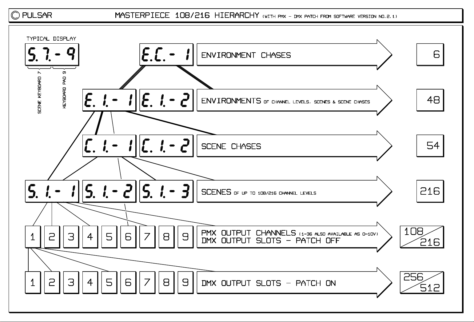
108 Masterpiece PMX Output Channel to 256 DMX Slot, Patching System.
This vastly expands the capability of the Masterpiece 108 by allowing it to drive 256 DMX Slots.
Why the name "Slot"? It is expected, in the next revision of the DMX Standard, that the term "Dimmer Levels" will
be renamed "Slots", since DMX is now used to control many parameters besides dimmer levels. Slots refer to the
bytes that flow one after the other in the DMX serial data stream - each having its own time slot. It aids our
explanation of the Patching System to refer to Masterpiece Output Channels or PMX Channels (Patch input) as
opposed to DMX Slots (Patch output).
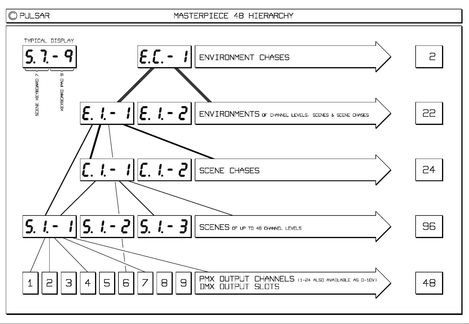
Patching Concepts:
Please see the Masterpiece Hierarchy diagram to see how the Patch fits into the scheme of things.
The Patch is particularly useful when controlling large numbers of intelligent lighting fixtures. For example, a
Masterpiece 108 can control just 6 Clay Paky StageScans but with the Patch it can now control 16 of them!
Often when intelligent lights are programmed, certain parameters are grouped together into Scenes. For example,
you might have a Scene which controls the colour discs of the odd number projectors and another scene for the even
one's colour discs. A scene for odd Gobo Selects and another for even Gobo Selects. Two scenes for odd and even
Gobo Rotation speeds. Two scenes for the front group and the back group's Zoom Lenses. One scene for all the
lamp control channels, etc.
This grouping can now be done by the Patch, for example, this allows just one Masterpiece Channel to control all
the Lamp Control Slots. With 16 projectors this saves 15 Masterpiece Channels. Two Masterpiece Channels to
control the odd and even colour discs - 14 channels saved. Two Channels to control the odd and even Gobo Select
discs - another 14 channels saved, and so on. It is likely, however, that you will want to control the Pans, Tilts and
Stoppers, for example, individually, but with these huge channel savings this presents no problem.
Logical layout - another function of the Patch is to allow you to lay out the Masterpiece in an efficient and logical
way. All the Irises could be patched to adjacent channels on the Masterpiece. Similarly the Stoppers. The Pans
and Tilts could be put side by side on the same Output Select Page, etc.
If you have some spare DMX Slots, you could address your projectors 10 or 20 apart for simplicity, leaving some
unused Slots between projector base addresses.
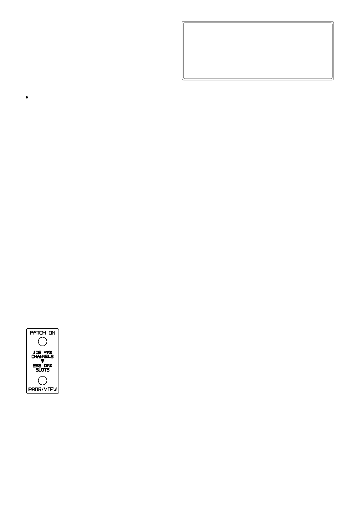
The Patch Key has three modes: Patch Off, Patch On and Program / View.
Patch Off - the Masterpiece works as before - the DMX Slots are identical to the PMX Channels.
Patch On - the Masterpiece's 108 PMX Output Channels are patched to 256 DMX Slots.
The PMX output is always unpatched and therefore exactly as it was before, as are the 36 0-10V
analogue outputs.
Programming or Viewing the Patch
One Masterpiece Channel can drive many DMX Slots but a DMX Slot can only be driven by one
Masterpiece Channel. Therefore the programming process is to select a particular DMX Slot and then
attach a Masterpiece Channel to drive it.
1. Press the Patch key to select Prog/View and enter the (new) Security Code.
2. Press the Forward or Reverse Manual Step keys to work your way through the 256 DMX Slots. These keys are
repeat keys and quickly count through the slots if held pressed. The display shows "S.###" (meaning Slot
Number) while the Forward or Reverse key is pressed and "C.###" (meaning output Channel Number) when the
key is not pressed. When not pressed, after two seconds, the display toggles between "S.###" and "C.###".
3. Having selected a particular Slot, use the Output Select keys O1-O6 and the Keyboard keys 1-18 to select the
Masterpiece Channel to drive that slot. "C.###" appears in the display.
Paul F. Mardon, Technical Director, 28-10-98
File: MPN.Sam PAGE 10 of 11
Page 13

Masterpiece
Software
Upgrades
NEW IN SOFTWARE VERSION "MASTERPIECE MAIN No.2.1" - 28-10-98 - continued
4. Additional Feature - a DMX Slot may be given a permanent fixed level - rather than attaching it to a
Masterpiece Channel. This can be useful for house lights, for motors which must always run or to ensure certain
slots are always on or off, etc. To do this use the Grand Master during patch programming to set the desired
level of the Slot. You can also move the Grand Master to see which parameter a particular Slot controls and then
press the desired Keyboard key to return the Slot to Masterpiece Channel control. When a Slot has a fixed level
the display changes from "C.###" to "###.#" to show its percentage. Forty levels of brightness are available from
0.0% to 100.0%.
5. To finish Prog/View Patch, just press the Patch key once more.
Blinking LEDs - if you don't press an appropriate key or move the Grand Master within 6 seconds, the LEDs start to
blink to show you which keys should be pressed.
Sacrifice - to provide the necessary memory for the Patch, some of the memory that was used by the 6 Environment
Chases has been taken. These can now have a maximum of 102 steps each instead of the 124 they were allocated
previously. So DO NOT use this new software if you have Environment Chases with more than 102 steps and you
cannot reprogram them to be within the 102 limit.
Patch Memory / Card Transfer - each of the 18 Keyboards may be enabled or disabled for transfer during memory
to card or card to memory. Please note that the Patch information is transfered with the E3 keyboard.
New software for the Masterpiece Replay Unit is also available. This allows the Replay Unit to replay shows
made on the Masterpiece 108, which use the Patch and 256 DMX channels. The software needed is:
EPROM - Masterpiece Replay Unit, Main No.2.1, © Pulsar 28-10-98 (or later)
DMX Microprocessor - M/Piece 108 / RPU, DMX / MIDI V2.1, © Pulsar 28-10-98 (or later).
New software for the Masterpiece Screen Driver is being written. This will be a free upgrade which we hope will
be available very early in 1999. While in Prog/View Patch it will automatically display the Patch's Channel Map as
you program it and to allow you to type in the function of all the 256 DMX slots. We expect there to be 13 Screens of
Patch data - 20 Slots per screen. Using the Forward or Reverse Manual Step keys to select a Slot will put you into
the correct screen. The Masterpiece Channel driving that Slot will automatically be shown. While in Prog/View Patch
you will be able to use Screen Text Mode to enter details about that Slot's function. If you keep Output Select O1-O6
pressed, the screen of data about those Masterpiece Channels will be displayed to help you select the desired
Channel. The Masterpiece software necessary to do this is already built into the 2.1 upgrade.
OTHER NOVELTIES
New Security Code for Set User Access Levels and for programming the Patch - see the Security Code sheet. The
Operator's Code 12,6,7,1 now only works for Memory / Card transfers.
"Appendix Two - Pulsar Masterpiece - Remote Control by RS232." This explains how to control a Masterpiece
108 from a computer or other source of RS232 / RS423. It shows how to do anything from activating a single channel
to a complete lightshow remotely. The concept is similar to "Remote Control by MIDI" in Appendix Three.
Controls Engaged / Which Chase? The key's LED now blinks when engaged to warn that moving the Speed or
Slope sliders or touching a Chase Control key will change the parameters of the engaged chase.
BUG FIXES
If the Scene Fade Time sliders are brought to zero they no longer become engaged until they move away from
zero - just like the Channel Level / Keyboard Master sliders.
Coming out of Program Chase Sequence after editing the Step Times of an Environment Chase no longer flips it
into Bass Burst mode.
Switching off the Masterpiece stops the DMX transmission cleanly - without sending incorrect levels first.
NEW IN SOFTWARE VERSION "MASTERPIECE 108 MAIN No.2.2" & "REPLAY UNIT MAIN No.2.2" - 28-09-99
BUG FIX - occasional loss of MIDI Remote Control comands - problem solved in version No.2.2.
Paul F. Mardon, Technical Director, 28-09-99
File: MPN.Sam PAGE 11 of 11
Page 14

Masterpiece
Software
Upgrades
NEW IN SOFTWARE VERSION "MASTERPIECE MAIN No.2.1" - 28-10-98
SECURITY CODES
The NEW Programmer's Code:
3, 4, 10, 9
This code is required to enter: Set User Access Levels and to Program / View the Patch (the
108 PMX Channel to 256 DMX "Slot" patching system released in Software Version 2.1 as a free
upgrade, which allows a Masterpiece 108 to drive 256 DMX channels or "slots").
This code should not be disclosed to people you do not want to program your Masterpiece.
The Operator's Code:
12, 6, 7, 1
This is now the ONLY code that allows Card / Memory transfers.
* * * * * PLEASE REMOVE THIS SHEET * * * * *
if you do not want the Lighting Operator to be able to change the User Access Levels or to
Program / View the Patch.
Paul F. Mardon, Technical Director, 28-10-98
File: MPN.Sam PAGE 11a of 11
Page 15
Masterpiece
108 PMX Channel to
256 DMX Slot
Patch - Examples
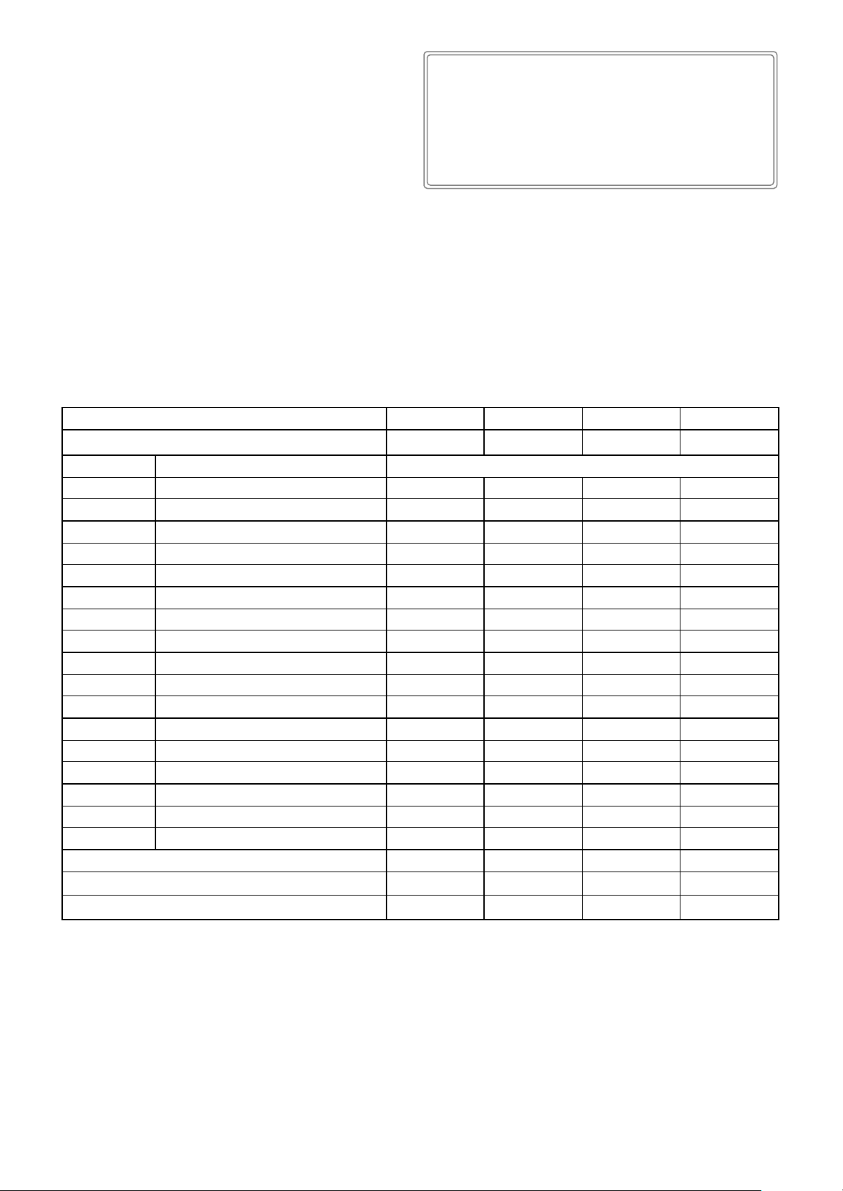
Software Upgrade from No.2.1 (free) for the Masterpiece 108 provides a Signal Patch.
This allows the 108 Masterpiece PMX Channels to be patched to drive 256 DMX Slots (channels). Thus, for example, up to 16 Clay Paky
Stage Scans can now be controlled whereas before the patch upgrade, only 6 could be controlled!
The Patch groups projector channels together - just as you would have often done in practice but previously by using Scenes. Now each
Masterpiece channel is able to control groups of projector channels, vastly expanding the Masterpiece's capabilities.
In the table below various example arrangements are shown but the groupings can of course be varied to suit the requirements of your
particular show.
If, for example, Prism Select has the number 2 in the table, this could mean that Odd Projector Prism Selects are controlled by one channel
and Even Projector Prism Selects are controlled by a second channel.
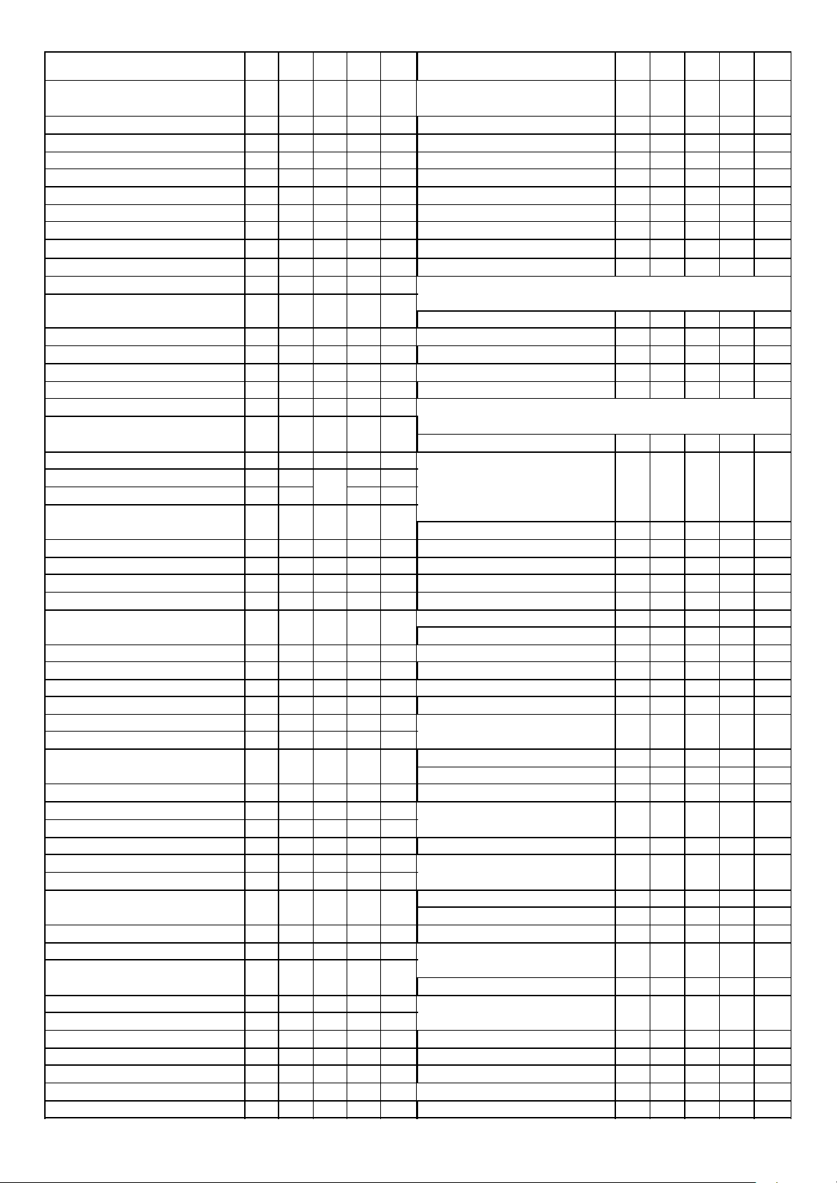
Number of Stage Scans Driven ðð
Stage Scan Channel òò
No Function No of Masterpiece PMX channels used per function
1 Iris 4 12 8 6
2 Colour Disc 2 4 4 6
3 Prism & Frost 2 4 4 6
4 Dimmer/Strobe 16 12 8 6
5 Pan 16 12 8 6
6 Tilt 16 12 8 6
7 Multi Step Zoom 4 4 4 6
8 Focus 16 12 8 6
9 Prism Select 2 2 4 6
10 Prism Rotation 2 2 4 6
11 Fixed Gobo Select 2 3 4 6
12 Rotating Gobo Select 4 4 8 6
13 Gobo Rotation 8 12 8 6
14 Red 4 4 8 6
15 Green 4 4 8 6
16 Blue 4 4 8 6
17 Lamp Control 0 1 1 6
16 12 8 6
No of Masterpiece PMX channels used ðð
No of DMX slots (output channels) driven ðð
106 108 105 102
256 204 136 102
Paul F. Mardon, Technical Director, 28-10-98
File: PatchEg.Sam PAGE 1 of 1
Page 16

Masterpiece 216
Enhanced
Features
THE INITIAL SOFTWARE FOR THE MP216 IS "MASTERPIECE MAIN No.2.2" - 28-09-99
Output Channels
The MP216 has 216 'PMX' Output Channels. Press the O1-O6 / O7-O12 key to switch the six Output Select keys
between O1-O6 for channels 1-108 and O7-O12 for channels 109-216.
Patching System
The 216 PMX Output Channels are patchable to 512 DMX Slots (twice the capacity of the MP108).
Eight Shows
Memory capacity is provided internally for 8 separate shows.
At switch on the software version is displayed e.g. "No.2.2" followed by the number of the current show e.g. "Sho.1".
To see the number of the current show at any time, simply press the Show Select key on it's own.
To change show: WHILE pressing the Show Select key press a keyboard key 1-8. When you release the Show
Select key, the Masterpiece will switch to the new show.
Each of the eight shows may be selected remotely by MIDI and RS232 (PMX) - see Appendices Two and Three.
Memory Cards
Each MP216 show needs 64K of memory (32K for a MP108). So a 64K card can store one show, 128K two shows,
256K four shows, 512K eight shows.
Memory to Card / Copy Current Show to Another Show
Any of the internal shows (Sho.1 - Sho.8) may be copied to any position in the card (Sho.9 - Sh.16). The source
show is the current one. When you press the Memory to Card key the MP216 tries to select the most likely
destination show, however you can change this by pressing the Show Select key plus a Keyboard key. The
destination show can even be another internal show - this provides the Copy Show to Show function. As usual the
Keyboard Select keys may be used to select which parts of the memory are transferred. The display indicates the
source and destination shows, when you are happy with these, enter the code.
Card to Memory / Overwrite the Current Show with Another Show
When you press the Card to Memory key the MP216 tries to select the most likely source show to overwrite the
current show, however you can change this by pressing the Show Select key plus a Keyboard key. The source show
may be changed to any show stored in the card (Sho.9 - Sh.16) or any internal show (Sho.1 - Sho.8) - this provides
the Overwrite Current Show with Another Show function. The rest as above ...
Swap Memory and Card / Swap Current Show with Another Show
Both of the above together.
Masterpiece 108 shows
The MP216 can read MP108 cards and play them back correctly. It can also write MP108 cards but obviously only
the first 108 channels are functional. A MP108 can read MP216 cards and play back the first 108 channels.
Future plans
A Chase Generator for the rapid creation of complex chases and effects, and the efficient use of Scenes is planned for
the next free software upgrade.
Paul F. Mardon, Technical Director, 28-09-99
File: MPN.Sam PAGE 12 of 12
Page 17
MASTERPIECE 216 108 48 RU RU2 MASTERPIECE 216 108 48 RU RU2
Front Panel Features Chase Control
DMX Output Slots (Channels) 512 256 48 256 512 Forward Manual Step
PMX Output Channels 216 108 48 108 216 Reverse Manual Step
Scenes 216 216 96 216 216 Chase Direction
Scene Chases 54 54 24 54 54 Chase Step Source
Environments 48 48 22 48 48 Chase Type 1-Shot/Repeat
Environment Chases 6 6 2 6 6 Fade/Step Chase In
Which Chase?/Engage Controls
Output Pages 12 6 4 Speed Slider
Output/Keyboard-Master Sliders 18 18 12 Slope Slider
Output Monitor LEDs 18 18 12
33 33 33
33 33 33
33 33 33
33 33 33
33 33
33 33
33 33 33
33 33 33
33 33 33
Keyboard Section BNC Connector for Lamp
33 33 33
Keyboard Keys 18 18 12
Scene Keyboards 12 12 8 4 Digit Display
33 33 33 33 33
Scene Chase Keyboards 3 3 2
Environment Keyboards 3 3 2 Joy Stick
33 33
Environment Chase Keyboards 1 1 1
Mains
Keyboard Action Keys On/Off Switch (on front panel)
Latch/Flash
Swap/Solo
Swap All Like Keyboards
33 33 33
33 33
33 33
3
33 33 33
Mains
Theatre Section On/Off Switch (on back panel)
A-B Master Sliders
In/Out Fade Time Sliders
A-B Crossfade Mode Pad
Grand Master Slider
33 33
33 33
33 33
33 33
Supply Socket
Voltage Selector
Mains Fuse
Lamp Fuse
Output Control Keys Analogue Outputs
Freeze Output
Blackout/Restore
Memory Card
Card to Memory
Memory to Card
33 33
33 33 33 33 33
33 33 33 33 33
33 33 33 33 33
33 33 33 33 33
PMX Output Sockets 2 2 2 2 2
DMX 512 Output Sockets 2 2 2 1 1
Audio Inputs
33 33
33 33 33
33 33 33 33 33
33 33 33 33 33
33 33 33
1-36 1-36 1-24 1-18 1-18
Speaker Level Jack Sockets 2 2 2 2 2
Other Keys / Functions Pre-Amp Level Jack Sockets 2 2 2 2 2
Show Select
Set User Access Level
PMX - DMX Patch
Output Bank Select
Release Sliders
Slider Action
Sound to Light Thru Socket
Circuits
Monitor
33 33
33 33 33
33 33 33 33
33
33 33 33
33 33 33
33 33 33 33 33
33 33 33 33 33
Microphone Level Jack Socket 1 1 1 1 1
PMX Remote Control
33 33 33
Midi Remote Control
In Socket
Options Switch
33 33 33 33
33 33 33 33
33 33 33 33
Remote Control
Programming Keys Input DIN Socket
Save Output To Scene
Program Chase Sequence
Save Environment
Rec.Env.Chase In Real Time
Rec.Env.Chase Step Times
Copy
Screen Text Mode
33 33 33
33 33 33
33 33 33
33 33 33
33 33
33 33
33 33 33
Dimensions
Width 19" 19" 19" 19" 19"
Height 14" 14" 10.5" 1.75" 1.75"
Depth including plugs & sockets 6" 6" 6" 8" 8"
Designer 8U Case
33 33 33 33 33
33 33 33
MPSPEC.SAM - Modified 22/09/99
Page 18
Page 19
Page 20

Page 21

Page 22

Page 23

CONTENTS
Page
1 CONTENTS
2 TERMINOLOGY - GLOSSARY OF TERMS
3 SPECIFICATION
4.1 BACK PANEL - Diagram
4.2 - Inputs, Outputs, Fuses and Switches
5 FRONT PANEL - THE LEDS, SLIDERS AND PADS, THEIR FUNCTIONS AND USE
0 - Diagram
5.1 - The LEDs - general information
5.1 - Blinking of the LEDs
5.1 - The 4 digit display
5.1 - The Output Monitor LEDs
5.1 - The Output Select/Release/View pads
5.2 - The 18 Sliders, Channel Level & Keyboard Master mode
5.3 - Release Sliders
5.3 - The Keyboard
5.4 - The 4 Keyboard Action pads
5.4 - The 18 Keyboard Select/Release/View pads
5.4 - Scene Keyboard No.12
5.5 Programming pads - Save Output To Scene - Making/Modifying/Deleting
5.6 Programming pads - Program Chase Sequence - Making Scene Chases
5.7 - The Chase Controls
5.8 Programming pads - Save Environment of Channel Levels, Scenes & Chases
* - A-B crossfade controls
5.9 - Various other pads
5.9 - Joystick
6.1 PROGRAMMING - General, Concept
6.1 - Strobes
6.1 - Sound-to-light
6.1 - Intelligent lighting
6.2 - The Joystick
* - Theatre
* - Environmental Control
7 OPERATION - Concept
* - Theatre
* - Environmental Control
7 OTHER INFORMATION
APPENDIX 1 - PULSAR RS232 DATA TRANSMISSION FORMAT
* APPENDIX 2 - REMOTE CONTROL BY RS232
APPENDIX 3 - REMOTE CONTROL BY MIDI
APPENDIX 4 - USING THE REMOTE CONTROL SOCKET
PROGRAM RECORD SHEETS
- Output Channel Assignments
- Scenes
- Scene Chases
- Environments
- Environment Chases
* This feature will be available in future software upgrades.
Page 1 - for Pulsar Masterpiece software version No.1.0, December 1990.
Page 24

BUTTON - See PAD.
BLINKING - A LED which briefly flashes to FULL or ZERO brightness once every 2 seconds to attract your
attention, as a prompt requesting a key press or as a warning or to show that its slider is engaged.
CARD - A credit card sized device which fits into a slot in the front panel, for saving/exchanging/loading the
contents of the Masterpiece’s memory for backup, changing shows and transfer between Masterpieces.
CHANNEL - 1 of the 108 outputs from the Masterpiece which could control a spotlight, motor, strobe, another
controller, intelligent spotlight ch.,etc.
CHANNEL LEVEL - The level of an output channel. The resolution is 8 binary bits so there are 256 possible
levels between 0 and 100%.
DMX512 - A serial data transmission system for sending the channels levels of up to 512 channels.
ENGAGED - When a slider is actually "linked" or "connected" to a level it can control. E.G. the first of the 18
sliders may be engaged to have overriding control of the Level of Channel 1.
ENVIRONMENT - A combination of a number of Channel Levels, Scenes at various levels and Scene Chases at
various levels, saved onto one Keyboard pad of an Environment Keyboard for recall whenever required.
ENVIRONMENT CHASE - A chase sequence whose steps are Environments - a complete lighting performance
on one button.
KEY - See PAD.
KEYBOARD - the bottom row of 18 pads.
KEYBOARD MASTER - One of the 18 Sliders being used in this mode can take overriding control of a Keyboard
pad to allow a 0-100% level rather than the on/off action of the pad.
LED - Light Emitting Diode.
PAD - Metal TOUCH sensitive PAD on front panel for use as a fast switch.
PAGE - or Block or Window, which allows you to see 18 of the 108 channels.
RAM CARD - See Card.
RELEASE - disengage a slider(s) so that it no longer has overriding control of a Channel Level or Keyboard
Master Level.
RS232 - A serial data transmission system. See appendices for full spec.
VIEW - VIEW the level of a Channel, Keyboard Master or other slider by putting its value into the 4 digit display.
SCENE - a snap shot, recorded in memory, of the levels of the 108 channels.
SCENE CHASE - a means of stepping automatically through selected scenes.
SLAVE - another Masterpiece which controls an extra 108 channels under the direction of a master Masterpiece.
TOUCH PAD - Metal TOUCH sensitive PAD on front panel used as a fast switch.
MASTER - a slider which controls the levels of many channels simultaneously.
MIDI - Musical Instrument Digital Interface - a serial data transmission system.
Page 2 - for Pulsar Masterpiece software version No.1.0, December 1990.
Page 25

A 108 channel memory desk to control any piece of equipment able to accept 0-10v analogue or RS232 or
DMX512 serial digital inputs.
Designed for the control of:
1. Theatre Lighting
2. Band Lighting A universal,
3. Discotheque Lighting fully programmable,
4. Intelligent Spotlights future proofed controller.
5. Environmental Lighting
STRUCTURE:
108 Channels - add Masterpieces, switched to slave mode, to expand 108 channels at a time, without
theoretical limit.
216 Scenes of the 108 channel levels with fade in and out times
54 Scene Chases, may run concurrently, with individual speeds, slopes etc.
48 Environments of Channel Levels, Scenes and Scene Chases
6 Environment Chases - each a complete light show on one button.
CONCEPT: The Masterpiece should feel familiar, with features from our Touch Panel, Control Desks, Rock
Desks and Modulators. Then, as you start to learn and understand more about the Masterpiece’s power and
versatility as a fully programmable controller, we hope you will agree that it really deserves its name.
SPEED: The ultimate in both programming and operation thanks to its conceptual simplicity and having one
Touch Pad for every requirement.
FROM A THEATRICAL POINT OF VIEW: Fully automatic crossfades or manual crossfades using the A and B
masters. Fade In and Fade Out time sliders to create/override the values stored with each scene. Add in any
amount of the other 216 scenes at any time. Individual, overriding control of the 108 channels always available.
Grand Master. Black Out.
OUTPUTS: Channels 1-36 available as 0-10v analogue.
Channels 1-108 transmitted in both RS232 and DMX formats - Pulsar Universal Interfaces are available to
translate RS232 or DMX (or MIDI) signals into 36 more channels of 0-10v analogue each.
MIDI THRU socket.
INPUTS: Audio for Sound-to-Light and Bass and Treble Chases.
RS232 and MIDI for total remote control of ANY Touch Pad or Slider.
DIN socket for Remote Environment/Environment Chase Control.
SOUND-TO-LIGHT: Pulsar Modulator’s Sound-to-Light circuits built in, 3 zones of 4 channels, each patchable at
any level over the 108 channels.
SECURITY: Using his security code, the "Programmer" may deny access by the "Operator" to any touch pad or
slider.
OTHERS: 70 Touch Pads, 25 Sliders, 108 LEDs:
18 Keyboards of 18 pads, Latch/Flash/Swap/Solo/A-B Master Keyboard modes, 4 Digit Display, Sound-to-Light
Monitor, Joystick with position/velocity, Freeze Output, Master/Slave desk, Chase section: Manual Step Fwd/Rev,
Speed, Slope, Bass/Treble Burst, One-Shot/Repeat, Use Scene Fade Times, Record light show in Real Time,
Copy .....
MEMORY: Internal memory non volatile. RAM card for backup, changing shows and transfer between
Masterpieces.
SIZE: Width 19", Height 14" (8U), Depth 3" (6" including plugs & sockets).
MOUNTING: Free standing in its own specially designed case.
Console mounting in its own specially designed case. 19" Rack mounting.
Page 3 - for Pulsar Masterpiece software version No.1.0, December 1990.
Page 26

Page 27

Page 28

MAINS SUPPLY - 100-130/200-240V, 50-60Hz, single phase, 15 watts max.
MAINS VOLTAGE SELECTOR - MUST BE set for 120V / 240V.
MAINS SWITCH - With indicator neon.
MAINS & LAMP FUSES - 1 Amp, 5 x 20 mm.
MAINS SOCKET - IEC 22, 3 pin, male socket (kettle socket). A moulded lead with IEC female socket to British
13amp plug is provided. To fit another type of plug, cut off the British 13amp plug and observe the following
colour code: Brown = Live (Hot), Blue = Neutral, Green/Yellow = Earth (Ground). The Masterpiece must be
earthed.
ANALOGUE OUTPUT DIN SOCKETS - The first 36 of the 108 channels are available here as 0-10v analogue
signals. There are 6 DIN sockets, 6 channels each. Pin connections: Pin 1 not used, 2 = earth (ground),
3-8 = channels 1-6, 7-12, etc. - as printed on the back panel.
The outputs are via isolating diodes so they may feed the same equipment as other controllers - the highest taking
priority.
DMX512 DIGITAL OUTPUT 5 PIN XLR SOCKETS - All 108 channels levels are transmitted in the DMX512/1990
serial digital format to any device capable of receiving it. Use twin core screened cable. Pin connections:
Pin 1 = Screen Earth, Pin 2 = Signal-, Pin 3 = Signal+.
NOTE: The end of the DMX line MUST ALWAYS be terminated with a 100 ohm resistor connected between
Signal+ and Signal-. This resistor can conveniently be mounted in a 5 pin XLR plug which should be inserted in
the last device on the DMX line.
RS232 DIGITAL OUTPUT 3 PIN XLR SOCKETS - All 108 channels levels are transmitted in Pulsar’s RS232
serial digital format (full details in Appendix 1) to any device capable of receiving it which include Clay Paky
Intelligent Spotlights, Pulsar Universal Interfaces for conversion to 0-10v analogue channels, 36 channels per
Interface, computers etc.
Pin 1 = Earth, Pins 2 and 3 = signal. Use single core screened cable.
This data stream also contains key press and slider move information to drive a slave Masterpiece.
* RS232 DIGITAL INPUT/OUTPUT 3 PIN XLR SOCKETS
For use by Slave Masterpieces. The signal from the Master Masterpiece or the previous Slave Masterpiece
enters here and may link on to another Slave or proceed to the lights or other receiving equipment. A computer
could control the Masterpiece remotely via this input - see Appendix 2 protocol.
Pin 1 = Earth, Pins 2 and 3 = signal. Use single core screened cable.
AUDIO INPUT SOCKETS
1. One Microphone 1/4" mono jack socket
2. Two Pre-amp level (0.1v - 2.5v RMS) 1/4" stereo jack sockets (in/out)
3. Two Hi level (2.5v - 100v RMS) 1/4" stereo jack sockets (in/out)
Please note, when feeding a signal from a stereo system, both left and right audio signals must be supplied to the
Masterpiece to produce faithful Sound-to-Light.
* MIDI IN - for total remote control of ANY Touch Pad or Slider.
See Appendix 3 for protocol.
MIDI THRU - retransmits the MIDI IN signal to the next device in the MIDI signal chain.
* MIDI SELECTOR SWITCH
* REMOTE CONTROL DIN SOCKET - for Environments and Environment Chases.
* This feature will be available in future software upgrades.
Page 4.2 - for Pulsar Masterpiece software version No.1.0, December 1990.
Page 29

Many of the sections that follow also refer to other sections, so you may find it easier to read quickly through all of
them to get a rough idea of the contents and then re-read them more carefully.
THE LEDs - GENERAL INFORMATION - four colours - Green, Yellow, Amber and Red are used to distinguish
different functions. Some LEDs, the 18 Keyboard LEDs for example, change colour to match their function.
Green - Scene Keyboards, Scene Keyboard Select, Save Output To Scene.
Yellow - Scene Chase Keyboards, Keyboard Select and Chase Control LEDs.
Amber - Environment chases.
Red - Environment Keyboards, Environment Keyboard Select, Save
Environment, Output Monitor Leds and other important functions.
BLINKING OF THE LEDs - Some LEDs can blink briefly to FULL or ZERO, once every two seconds, to attract
your attention for the following reasons:
1. As a warning e.g. Black Out, Grand Master less than 100%.
2. As a prompt if the required key has not been pressed within about 5 secs.
3. The Output Monitor LEDs blink if the Channel Levels are being overridden by a slider level.
4. The Keyboard LEDs blink if their levels are being overridden by slider levels.
THE 4 DIGIT DISPLAY is used to display a wealth of information:
1. Pairs of numbers for matching a slider’s position to the stored level for a smooth pick up by the slider. The
current value is shown on the left, the slider position on the right.
2. Levels from 0.0 to 100.0% with the full 256 possibilities all shown.
3. Time from 0.00 to 360.0 seconds for Manual Slope, Fade In and Out Times.
4. Beats Per Minute from 0.10 to 1500 for the Speed control.
5. Pairs of numbers for the X and Y values of the Joystick.
6. Pairs of numbers for the A and B Master levels.
7. Numerous four letter words are displayed as well as possible for this type of display - a little imagination is
sometimes required!
N.B. When only two digits are available to display the number 100, the Roman number "C" is used.
THE OUTPUT MONITOR LEDs - the 18 red LEDs along the top edge.
These allow you to see the levels of a
choose which
THE OUTPUT SELECT/VIEW/RELEASE PADS - 6 pads with the following uses:
1. To SELECT which
and which 18 Channel Levels the 18 Sliders are able to adjust/view/release.
2. To VIEW the level of an output channel - two methods:
a. While keeping a finger pressed on one of these 6 pads, move the slider of the channel whose level you wish
to view, its level will be displayed in the 4 Digit Display without changing that level.
b. *While keeping a finger pressed on one of these 6 pads, press one of the 18 Keyboard pads - the channel
number (1-108) will be displayed until you remove your finger from the Keyboard pad when the Channel Level
will be displayed.
3. To RELEASE all/any slider(s) engaged to Channel Levels within a page of 18 output channels, keep one of
these 6 pads pressed and at the same time press the RELEASE SLIDERS pad.
pageorwindow
page
of 18 output channels (1-18, 19-36 etc.) the Output Monitor Leds are displaying
page
of 18 of the 108 output channels. Use the 6 Output Select pads to
of 18 you are looking at: 1-18, 19-36, 37-54, 55-72, 73-90 or 91-108.
* This feature will be available in future software upgrades.
Page 5.1 - for Pulsar Masterpiece software version No.1.0, December
Page 30

THE 18 SLIDERS - Have two functions:
1. CHANNEL LEVEL mode - to adjust the levels of the 108 Output Channels,
2. KEYBOARD MASTER mode - to adjust the levels of Scenes, Scene Chases, Environments or Environment
Chases instead of using the Keyboard, which can only switch them off or on.
The LEDs in the SLIDER ACTION pad and RELEASE SLIDERS pad indicate whether the 18 sliders are
controlling CHANNEL LEVELS or are operating as KEYBOARD MASTERS.
To change modes:
a. Pressing the SLIDER ACTION pad will TOGGLE mode,
b. Pressing any of the 6 OUTPUT SELECT pads switches to CHANNEL LEVELS
c. Pressing any of the 18 KEYBOARD SELECT pads switches to KEYBOARD MASTERS
Example of use - change the level of channel no.12:
1. Press Output Select pad no.1 to select channels 1-18 and CHANNEL LEVELS mode.
2. Move slider no.12, a pair of numbers will appear in the display, on the left is the current level of channel
no.12, on the right is the slider position which changes as you move it.
3. When the pair of numbers in the display match, the slider becomes
have
overriding
4. Output monitor LED no.12 will change with the slider position but it will also BLINK to show that its level is
being overridden by the slider rather than being controlled by any scene or chase that may be active.
5. To
Example of use - change the level of Scene Chase no.3:
1. Press Keyboard Select pad
2. Move slider no.3, a pair of numbers will appear in the display, on the left is the current level of Scene Chase
3. When the pair of numbers in the display match, the slider becomes
4. Keyboard LED no.3 will change with the slider position but it will also BLINK to show that its level is being
5. To
release
finger on RELEASE SLIDERS then move slider no.12. See Release Slider section for alternative methods.
mode.
no.3, on the right is the slider position which changes as you move it.
now have
overridden by the slider rather than being controlled by any environment that may be active.
overriding
release
you finger on RELEASE SLIDERS then move slider no.3. See Release Slider section for alternative
methods.
control of its level.
control of channel 12’s level from the slider back to any active scenes and chases, keep your
Scene Chases no.1
control of its level.
control of Scene Chase 3’s level from the slider back to its pad or any active environment, keep
to select Scene Chases 1-18 and KEYBOARD MASTERS
engaged
engaged
to the channel and you now
to Scene Chase no.3 and you
PARKING SLIDERS - To put the 18 sliders to ‘0’ for example,
levels or Releasing them, keep a finger pressed on any of the 6 Output Select OR 18 Keyboard Select pads while
moving the slider(s). This is equivalent to VIEW.
Page 5.2 - for Pulsar Masterpiece software version No.1.0, December 1990.
without
affecting their Channel or Keyboard Master
Page 31

RELEASE SLIDERS - The pad between sliders 6 and 7. Use it to disengage sliders from having overriding
controlling of CHANNEL LEVELS or KEYBOARD MASTERS in any of these four ways:
1. RELEASE ONE SLIDER:
a. Firstly ensure that the required OUTPUT SELECT pad or KEYBOARD SELECT pad is selected and ensured
that SLIDER ACTION is set to CHANNEL LEVELS or KEYBOARD MASTERS as required.
b. While keeping a finger on RELEASE SLIDERS, move the slider you wish to release. More sliders may be
released at the same time.
2. RELEASE UP TO 18 SLIDERS - while keeping a finger on RELEASE SLIDERS, press the required
OUTPUT SELECT pad to release up to 18 CHANNEL LEVELS from overriding slider control OR the required
KEYBOARD SELECT pad to release up to 18 KEYBOARD MASTERS from overriding slider control. More
OUTPUT PAGES or KEYBOARDS may be released at the same time.
3. RELEASE ALL ENGAGED SLIDERS - METHOD 1 - while keeping a finger on RELEASE SLIDERS, wipe
your finger over all 6 OUTPUT SELECT pads and all 18 KEYBOARD SELECT pads.
4. *RELEASE ALL ENGAGED SLIDERS - METHOD 2 - while keeping a finger on RELEASE SLIDERS, press
the SLIDER ACTION pad.
The 4 DIGIT DISPLAY will initially show "rEL’", then count the number of engaged sliders released. When you
finally remove your finger from the RELEASE SLIDERS pad, it will display "done". If none have been released or
no engaged sliders have been found to release, the final display will be "CNCL".
THE KEYBOARD - the bottom row of 18 pads.
These are used to switch on or off the Scenes / Scene Chases / Environments / Environmental Chases.
There are 18 monitor LEDs in the Keyboard pads which change colour to suit the function of the Keyboard:
Green for the 12 Scene Keyboards,
Yellow for the 3 Scene Chase Keyboards,
Red for the 3 Environment Keyboards,
Amber for the Environment Chases (Pads 1-6 of Environment Keyboard 3).
A Keyboard Pad can switch on a Scene at 100%. Should you want to fade that Scene up to 50% for example,
then this can be done by putting the 18 sliders in KEYBOARD MASTER mode and using the corresponding slider
instead. The Keyboard Pad’s monitor LED will fade up to 50% but will also blink to indicate that the slider has
overriding control of the Scene’s Level. The same is also possible of course for Scene Chases, Environments
and Environment Chases. To return control back to the pad or a program, the slider must be
RELEASE SLIDERS.
Other uses for the 18 Keyboard Pads:
1. During programming, to select the destination of a Scene / Scene Chase / Environments / Environment
Chase.
2. During programming of Scene Chases, to enter the Scenes that make the steps of the chase.
3. *For viewing, Channel Number + Level, Scene, Scene Chase, Environment, numbers + levels, fade timers etc.
4. *To engage the chase controls to a particular chase without switching that chase on or off.
5. *Entering your security code.
released
- see
Four Digit Display: e.g. "C1-7" = Scene Chase Keyboard 1, Pad 7.
* This feature will be available in future software upgrades.
Page 5.3 - for Pulsar Masterpiece software version No.1.0, December 1990.
Page 32

THE 4 KEYBOARD ACTION PADS:
Latch/Flash
Swap - on/off.
Swap - This Keyboard/All Like Keyboards - only available when SWAP is on.
* A - B Crossfade Mode
In the 4 Digit Display you will see: Ltch/FLSH, SWAP/SOLO, ALL/thIS, A-b/OFF
Each Keyboard may have the following Action:
FLASH - only the pad(s) pressed are on.
LATCH - the pads toggle ON/OFF or OFF/ON when touched.
Flash + Swap = SOLO - only the pad(s) pressed are on,
any others are temporarily turned off while pad(s) are pressed.
Latch + Swap = SWAP- only the last pad touched is on, any others are permanently turned off.
If the This Keyboard/All Like Keyboards pad is switched to All Like Keyboards mode, then the SWAP or SOLO
action takes place across any Keyboard which is also switched to the same mode.
* A - B Crossfade Mode - Display: "A-b" / "OFF"
The action of the Keyboard changes allowing you to select the next scene (red) to fade in using the A or B master
sliders. The current one is green but ready to be faded out. To use the fade in and fade out times stored with
each scene, the Forward or Reverse Manual Step pads are used.
More details to follow when this part of the software is implemented.
THE 18 KEYBOARD SELECT/RELEASE/VIEW PADS
The Masterpiece has 18 Keyboards with 18 pads each (324) - for reasons of practicality you can only
Keyboard at a time! There are:
12 Scene Keyboards - giving 216 Scenes
3 Scene Chase Keyboards - giving 54 Scene Chases
3 Environment Keyboards - giving 48 Environments + 6 Environment Chases
on Environment Keyboard 3, pads 1-6 (7-18 are 12 more Environments).
The 18 Keyboard Select/View/Release pads - have the following uses:
1. To SELECT which of the 12 Scene, 3 Scene Chase or 3 Environment Keyboards, the 18 Keyboard pads are
working, their LEDs are monitoring AND which 18 KEYBOARD MASTERS the 18 SLIDERS are able to
adjust/view/ release.
2. To VIEW the level of a KEYBOARD MASTER - two methods:
a. While keeping a finger pressed on one of the 18 Keyboard Select pads, move one of the 18 sliders
corresponding to the S/SC/E/EC whose level you wish to view, its level will be displayed in the 4 Digit
Display, without changing it.
b. *While keeping a finger pressed on one of the 18 Keyboard Select pads, press one of the 18 Keyboard pads -
the Keyboard and Keyboard pad number (e.g. E3-9) will be displayed until you remove your finger from the
Keyboard pad when the S/SC/E/EC’s Level will be displayed.
3. To RELEASE all/any slider(s) engaged to KEYBOARD MASTERS within a Keyboard, keep one of the 18
Keyboard Select pads pressed and at the same time press the RELEASE SLIDERS pad.
see
one
4. *To engage the chase controls to a particular chase without switching that chase on or off.
Scene Keyboard No.12 - S2L is a special Scene Keyboard for:
1. Patching 3 Real Level Zones of 4 channel Sound-to-Light through to the 108 output channels,
2. Crossfading between 4 Scenes using the Joystick,
3. *Choosing Velocity or Position mode for the Joystick.
See Programming Section for more detail.
* This feature will be available in future software upgrades.
Page 5.4 - for Pulsar Masterpiece software version No.1.0, December 1990.
Page 33

THE PROGRAMMING KEYS
SAVE OUTPUT TO SCENE saves the Levels of the 108 Output Channels onto a Scene pad. WYSIWYG - What
You See Is What You Get - what you see on the output is what you save as a Scene. There are 12 Scene
Keyboards (see KEYBOARD SELECT on page 5.4), Scene Keyboard 1 + Keyboard Pads 1-18 stores Scenes 118, Scene Keyboard 2 stores Scenes 19-36 etc., making a total of 216 scenes. However, we find it more useful
to think in terms of Scene Keyboard + Pad number - as shown in the 4 Digit Display - e.g. "S1-1", "S3-7", "S9.12"
etc. and this is the format we have used for the program record sheets we have provided at the back of this folder.
It is very important that you fill in these sheets as you go - it is difficult to remember what is saved on each pad a
few days later.
Creating Scenes from scratch
1. Put all Channel Levels to zero by:
a. Putting all 18 Keyboards into FLASH mode.
b. Releasing all sliders (see the RELEASE section on page 5.3).
c. Checking that this has allowed all the Output Channel Levels to fall to zero by scanning across the 6 Output
Select pages and watching the Output Monitor LEDs.
2. Use the 18 Sliders in Channel Level mode and the 6 Output Select pads, to set the 108 Output Channels to
the levels you require for your Scene.
3. Press the Save Output To Scene pad.
4. Select one of the 12 Scene Keyboards (if different from the current one).
5. Select one of the 18 Keyboard pads of your chosen Keyboard to save your Scene to.
Now you can
Develop more Scene(s) from your first by altering some of the Channel Levels and then repeating steps 3 - 5
And finally
Put all the sliders down to zero (for good house keeping) and then RELEASE them from having overriding control
of the Channel Levels so that when you press the pad(s) you can see and use your Scene(s). Now write the
details of the Scene on the Program Record Sheets provided at the back.
Modifying scenes / Developing new scenes from existing ones
1. Switch on the Scene to be modified on its own, at full (all sliders released, nothing switched on, on any
Keyboard, except the required Scene on the required Scene Keyboard, Grand Master to full).
2. Use the 18 Sliders in Channel Level mode to modify the Scene.
3. EITHER save the modified Scene back to the same Keyboard pad OR to another pad if the new Scene is a
development from the first.
4. Put all the 18 Sliders down to zero and RELEASE them.
Delete one scene - 2 methods:
1. Put Grand Master to 0 then Save Output To Scene to the Scene to be deleted.
2. Put all 18 Keyboards into FLASH mode. RELEASE all sliders. Check that this has allowed all the Output
Channel Levels to fall to zero by scanning across the 6 Output Select pages and watching the Output Monitor
LEDs. Save Output To Scene to the Scene to be deleted.
Delete many/all scenes
1. Start as 1. or 2. above to ensure all Output Channel Levels are 0,
2. Keep finger on S.O.T.S. pad to keep its LED on,
3. Select Scene Keyboard No1,
4. Wipe finger across Keyboard pads 1-18,
5. Select next Scene Keyboard,
6. Repeat 4 - 6 for the 12 Scene Keyboards,
7. Remove finger from S.O.T.S.,
8. Press S.O.T.S once more to switch it off.
Page 5.5 - for Pulsar Masterpiece software version No.1.0, December 1990.
Page 34

PROGRAM CHASE SEQUENCE - 2 types:
A. Scene Chases,
B. *Environment Chases - not yet available.
Programming Scene Chases
1. Firstly create all the Scenes that you need to make the steps of your Scene Chase - see page 5.5.
2. Press the Program Chase Sequence pad.
3. Tell the Masterpiece which of the 54 Scene Chases you are going to program by selecting one of the 3 Scene
Chase Keyboards and then pressing one of the 18 Keyboard pads.
4. The current Keyboard automatically switches back from a Scene Chase Keyboard to the Scene Keyboard last
used. If necessary, change to another Scene Keyboard, where your required Scenes are stored.
5. Press the Keyboard pads, to select the Scenes in the sequence required for the chase (changing Scene
Keyboard if required). The display shows the Scene number while pressed, followed by the step number.
6. Use the editing keys if necessary - see 9. and 10. below.
7. When satisfied, switch off Program Chase Sequence - the display shows "End".
8. Now use the chase controls as required to define the type of chase, speed, etc. - see THE CHASE
CONTROLS below.
Chase Editing Keys
9. Use the Reverse Manual Step pad to delete any mistakes - the display shows "dEL" while pressed, followed
by the decremented step number. This is now the last step of the chase.
10. The Forward Manual Step pad can be used to step through the chase, showing the scene number while
pressed followed by the step number.
Editing a Chase
11. The Scenes that are the steps of the chase may themselves be edited - see MODIFYING SCENES on
Page 5.5.
12. To edit the steps of the chase, follow steps 2. and 3. above, then Forward Step to the last correct step and
overwrite with new steps from there. Use the Editing Keys as required. Pressing Program Chase Sequence
again will display "End" if changes have been made otherwise "CNCL" if they haven’t.
Deleting a Chase
13. Follow steps 2. and 3. above.
14. Press the Reverse Manual Step pad (Delete) - the chase now has no steps - pressing the Forward Manual
Step would display "NONE".
15. Press the Program Chase Sequence pad again - display shows "End".
Note - the last Scene - "12.18" - is kept permanently as a Blackout Scene. A blackout step is often required in a
chase e.g. the last step of a One Shot chase.
* This feature will be available in future software upgrades.
Page 5.6 - for Pulsar Masterpiece software version No.1.0, December 1990.
Page 35

THE CHASE CONTROLS
There are 54 chases but only one set of controls - for practical reasons! Each chase has its own combination of
SPEED, SLOPE and the Chase Control pad settings, the controls are automatically engaged to the last chase to
be switched on - provided the WHICH CHASE LED is on. Pressing the WHICH CHASE pad will display "NONE"
if its LED is off, or, for example, "C3-7" (Scene Chase Keyboard 3, Keyboard pad 7) if its LED is on.
SPEED - needless to say, the Speed (and Slope) control has to be
chase before smoothly engaging and allowing you to change its level. The Speed control is calibrated in the
display in Beats Per Minute - from 0.1 (1 step per 10 mins) to 1500 (25 steps per second). Important parts of the
range, around 120 beats per minute for example, are expanded to give you very fine control.
SLOPE - 2 modes:
1. For
2. For
CHASE DIRECTION - 4 possibilities:
1. Continuous Forward - display shows "FFFF"
2. Continuous Reverse - display shows "RRRR"
3. Bounce - display shows "RFRF"
4. Alternate Bounce - display shows "RRFF"
Note - Alternate bounce is likely to be replaced by Bass bounce (reversing direction on the bass beat) in future
software revisions.
CHASE STEP SOURCE - 4 possibilities:
1. Manual stepping - from the Manual Step Forward & Reverse pads with Slope.
2. *Treble Burst - not yet available - works as Auto.
3. *Bass Burst - not yet available - works as Auto.
4. Auto stepping - uses the Speed and Slope controls.
Manual Chases
bottom to 0.00 seconds (stepping) at the top.
Auto Chases
to 0.0% at the top - pure stepping.
, the display shows the crossfade time in seconds. The range is from 360 second at the
, the display shows the crossfade percentage, 100% at the bottom - a complete crossfade,
matched
to the existing level of the particular
CHASE TYPE - ONE SHOT / REPEAT
Repeat - the Chase runs continuously.
One Shot - the Chase stops on the last step (forward) or the first step (reverse chases). The final step can be a
visible Scene or blackout if the special blackout scene, on Scene Keyboard 12, pad 18 "12.18", has been used.
*USE SCENE FADE TIMES - not yet available.
FORWARD MANUAL STEP - 2 uses
1. To Forward Step Manual Chases. Display shows " F" while pressed. Any of the 54 chases running, which
are
manual ones
Slope control.
2. While in Program Chase Sequence, the Forward Manual Step pad steps through a chase for editing,
displaying the Scene while pressed, followed by its step number.
REVERSE MANUAL STEP - 2 uses
1. To Reverse Step Manual Chases. Display shows "R " while pressed. Any of the 54 chases running, which
are
manual ones
slope control.
2. While in Program Chase Sequence, the Reverse Manual Step pad is used to DELETE a step and make the
previous one the last step of the chase. The display shows "dEL" while pressed followed by the
decremented step counter when released.
* This feature will be available in future software upgrades.
, will step forward. The time taken for each chase to step depends on the setting of its
, will step backwards. The time taken for each chase to step depends on the setting of its
Page 5.7 - for Pulsar Masterpiece software version No.1.0, December 1990.
Page 36

SAVE ENVIRONMENT OF CHANNEL LEVELS, SCENES & CHASES
Saves onto one pad, the complete ENVIRONMENT - the levels of any Output Channels controlled by the 18
Sliders, the Levels of any Scenes that are on, plus the levels of any Scene Chases that are on at that point in time.
WYSIWYG - What You See Is What You Get - the light show that you see is captured on to a single pad.
There are 3 Environment Keyboards (see KEYBOARD SELECT on page 5.4), Environment Keyboard 1 +
Keyboard Pads 1-18 stores Environments 1-18, Environment Keyboard 2 stores Environments 19-36,
Environment Keyboard 3 stores Environments 37-48 on Keyboard pads 7-18, (1-6 are used for Environment
Chases). However, we find it more useful to think in terms of Environment Keyboard + Pad number, as shown in
the 4 Digit Display - e.g. "E1-1", "E3-7", "E3.12" etc. and this is the format we have used for the program record
sheets we have provided at the back of this folder - don’t forget to fill in these sheets as you go.
Creating Environments from scratch
1. Create the Environment you wish to capture, using the Scenes and Scene Chases that you have already
created at the appropriate levels and add in some Output Channels levels if required.
2. Press the Save Environment pad.
3. Select one of the 3 Environment Keyboards (if different from the current one).
4. Select one of the 18 Keyboard pads of your chosen Keyboard to save your Environment to.
Now you can
Develop more Environment(s) from your first by altering the levels of the Channels, Scenes or Scene Chases and
repeating steps 2 - 4
And finally
Put all the sliders down to zero (for good house keeping) and then RELEASE them ALL from having overriding
control of levels. Switch off all Keyboard pads, on all Keyboards, so that when you press the Environment pad(s),
you can see and use the Environment(s) you have created. Now write the details of the Environment on the
Program Record Sheets provided at the back.
Modifying Environments / Developing new Environments from existing ones
1. Switch on the Environment to be modified, on its own, at full (all sliders released, nothing switched on, on any
Keyboard, except the required Environment on the required Environment Keyboard, Grand Master to full).
2. Use the 18 Sliders in Channel Level and/or Keyboard Master mode, to modify the Channel/Scene/Scene
Chase levels that make up the Environment.
3. EITHER save the modified Environment back to the same Keyboard pad OR to another pad if the new
Environment is a development from the first.
4. Put all the 18 Sliders down to zero and RELEASE them ALL.
Delete one Environment
1. Put all 18 Keyboards into FLASH mode.
2. RELEASE all sliders.
3. Check that this has turned everything off by scanning across the 6 Output Select pages and watching the
Output Monitor LEDs.
4. Save Environment to the Environment to be deleted.
Delete many/all Environment
1. Do 1 - 3 above to ensure all Output Channel Levels are 0,
2. Keep finger on Save Environment pad to keep its LED on,
3. Select Environment Keyboard No.1,
4. Wipe finger across Keyboard pads 1-18,
5. Select Environment Keyboard No.2,
6. Wipe finger across Keyboard pads 1-18,
7. Select Environment Keyboard No.3,
8. Wipe finger across Keyboard pads 7-18,
9. Remove finger from Save Environment pad,
10. Press Save Environment once more to switch it off.
Page 5.8 - for Pulsar Masterpiece software version No.1.0, December 1990.
Page 37

VARIOUS OTHER PADS
Memory-To-Card transfers the contents of the Memory of the Masterpiece (all the Scenes, Chases etc. that you
have programmed), to the Memory Card for security and for transfer between Masterpieces. One Card is
provided with each Masterpiece, new Cards need to have their battery inserted before use. The Masterpiece will
be able to check the Card’s battery voltage in later software versions. Battery life is 3-5 years. While you press
the pad, the display shows "M-C", followed by "COdE", which flashes to prompt you to enter your Security Code,
four presses on the Keyboard are required. The Security Code feature is not yet implemented - any four key
presses on the Keyboard will do. If you do not enter a code within 5 seconds, the transfer is cancelled and the
display shows "CNCL". The transfer takes about 2 seconds and the display counts down to zero to show you the
progress. The data transferred to the Card is verified and the message "PASS" or "FAIL" appears in the display.
Card-To-Memory - as Memory-To-Card but the data transfer is in the opposite direction - BE VERY CAREFUL
NOT TO PRESS THE WRONG KEY AND OVER-WRITE YOUR PROGRAM!
Swap Memory and Card - achieved by pressing both Memory-To-Card and Card-To-Memory. While the second
key is pressed, the display shows "SWAP".
* Change Security Code - display: "C.S.C." / "N.A." - this feature is not yet available. The Security Code
feature is not yet implemented - any four key presses on the Keyboard will do.
* Set User Access Levels - display: "S.U.A.L." / "N.A." - this feature is not yet available.
* Master / Slave - display: "No.1" / "N.A." - this feature is not yet available - there will however be three
possible modes:
1. Master mode - key presses and slider moves are transmitted to one or more Slave Masterpieces via the
RS232 digital output.
2. Slave mode - key presses and slider moves of a master desk are mimicked.
3. Solo mode - neither LED on - the Masterpiece works as a stand alone unit neither sending nor listening to key
press or slider move information.
* Future 1 - display: "Fut.1" / "N.A." - for future expansion.
* Record Environment Chase - In Real Time / Step Times
Display: "N.A." - this feature is not yet available.
* Copy - display: "COPY" / "N.A." - this feature is not yet available.
* Future 2 - display: "Fut.2" / "N.A." - for future expansion.
Blackout/Restore - display: "b.O." / "rES"
Blackout sends a zero level to all output channels but the monitor LEDs function normally. The Red Blackout
LED blinks as a warning.
Freeze Output - display: "F.O." / "GO"
When frozen, all the output channels hold their last level, otherwise the unit functions normally - use for
Plotting
Joystick - display: "XX.YY" - two numbers representing the X and Y positions of the Joystick. The Joystick only
works at present in position mode, velocity mode will be implemented in future software revisions. The Joystick
crossfades between 4 scenes on Scene Keyboard 12 - a Left, Right, Up and Down Scene - the Joy Centre Scene
is not in use at present. See Joystick Programming on page 6.2 for more detail.
. The red Freeze Output LED blinks as warning.
Blind
* This feature will be available in future software upgrades.
Page 5.9 - for Pulsar Masterpiece software version No.1.0, December 1990.
Page 38

General - Concept
1. Firstly, you need to make Scenes from the 108 Channel Levels. Some Scenes will be for use in their own
right and others will be prepared for incorporation into Scene Chases.
2. The second stage is to make Scene Chases from the pre-prepared Scenes.
3. Thirdly, you can create a complete atmosphere by using a number of Scene Chases at various speeds and
levels, together with a number of Scenes at various levels, plus a few Channel Levels and then this whole
setup can be saved onto one of the 48 Environment pads for recall, when required, by just pressing one
button.
To be able to do this, you need to be fully conversant with the functions of all the pads and sliders on the front
panel - you must read pages 5.1 - 5.9 first, where the programming of Scenes, Scene Chases and Environments
(Environment Chases are not yet available), is explained in full.
Strobe Control - The Masterpiece can be used to:
1. Switch on a strobe controller e.g. our Rainbow Strobe,
2. Enable the 3 zones of our Flexi-Flash controller, (it cannot drive Flexi-Flash directly),
3. Fire Pulsar Strobes directly, using the 36, 0-10v, analogue outputs on channels 1-36 OR on channels 37-108
via a Pulsar Universal Interface. To fire strobes directly, you need to make chases with the SLOPE control
set to Step. The Scenes in that chase need to contain Channel Levels at 100%, which will produce a 0 to
10v step on the required channels as the chase steps. Each 0 to 10v step will trigger the strobe, nothing will
happen as the Channel Level falls from 10 to 0v. You will need to make a lead to convert from the 6
channel DIN socket outputs to the 1 channel Jack Socket input on the Strobes.
Sound-To-Light
Twelve special Scenes can be made on Scene Keyboard No.12 which are for patching three, four channel
zones of Sound-To-Light, through to the 108 output channels. The words at the top of the 18 Keyboard pads
apply just to this special Scene Keyboard No.12.
Example: make a Scene for Bass zone 1.
Set the Channel Levels to the MAXIMUM level wanted for each of the Channels required to come on with the Bass
on zone 1. Now Save Output To Scene to Scene Keyboard No.12, Keyboard pad No.1 "12-1". The Bass of the
music will modulate the brightness of the lights between zero and the levels set by the Scene.
Intelligent lighting
It is possible to program a complete Scene containing Iris, Colour, Pan, Stopper, Pan and Tilt information for each
Scene Chase step - HOWEVER this is NOT the best way - it is far better to use "Modular Programming"
techniques. Here is an example for Golden Scans to give you ideas:
1. Make 6 Scenes on Scene Keyboard 1, pads 1-6, which are:
"S1-1" - all Irises together to full.
"S1-2" - all Colours together to full.
"S1-3" - all Gobos together to full.
"S1-4" - all Stoppers together to full.
"S1-5" - all Pans together to full.
"S1-6" - all Tilts together to full.
2. Make a Scene with ONLY colour information - each Golden Scan a different colour: "S1-7".
3. Make a Scene, with only Pan and Tilt information, with the beams all pointed on a central point: "S1-8".
4. Make a slow Gobo chase, 2 steps are needed: 1. All Gobos to full ("S1-3"), 2. Blackout (Scene "12.18"),
Slope at crossfade: "C1-1".
5. Now make a stopper chase - 8 steps, 1 on at a time, Slope at step:"C1-2".
6. Now make a movement chase with ONLY the Pan and Tilt information in the Scenes of this chase: "C1-3".
Cont....
Page 6.1 - for Pulsar Masterpiece software version No.1.0, December 1990.
Page 39

Using these
1. Switch on the following: "S1-1" - Irises open, "S1-7" - one of each colour, "S1-8" - Pans and Tilts on central
point, "C1-2" - the Stopper Chase and "C1-1" - the Slow Gobo Chase. Save the result on Environment pad "E1-1".
2. "S1-1" - Irises open, "S1-2" at 55% - Colours rotating slowly, "C1-1" - Slow Gobo Chase, "S1-4" - Stoppers
open, "C1-3" - Movement Chase, Save the result on Environment pad "E1-2".
Just a few ideas to fire your imagination! Programming in this way is fast, versatile and creative. To our
knowledge, OSKA and the Masterpiece are the only controllers in the world capable of it.
The Joystick crossfades between 4 scenes on Scene Keyboard 12 - a Left, Right, Up and Down Scene - the Joy
Centre Scene is not in use at present. These Scenes need to be switched on for the Joystick to work, although
you could just use the Left and Right Scenes on their own for example.
For use with Intelligent Spotlights for moving the light beams, proceed as follows:
1. Make a Left Scene which just contains the Pan information for the left limit of movement. You can use the
Tilt as well to find the positions but remove the Tilt levels just before Saving Output To Scene on 12.13.
2. Make a Right Scene which just contains the Pan information for the right limit of movement on "12.14".
3. Make an Up Scene which just contains the Tilt information for the upper limit of movement. You can use the
Pan as well to find the positions but remove the Pan levels just before Saving Output To Scene on 12.16.
4. Make a Down Scene which just contains the Tilt information for the lower limit of movement on "12.17".
You should find that the beams move around fairly well together but a little trial and error is sometimes required to
optimise the movement. The Joystick doesn’t quite go to 0% or 100%, so you may need to make scenes slightly
beyond the limits actually required. Unfortunately, it is not possible to switch these scenes on to modify them, so
we recommend that you make the scenes on Scene Keyboard 11 for example, which
save a copy of them onto the special Scene Keyboard 12 ones.
tools
, you can make a number of Environments - for example:
can
be modified, and then
LIMITS - to make a practical product, at a sensible price, we have been careful not to over-engineer the
Masterpiece, this means that there are a few limits on the use of memory which you shouldn’t meet in practice but
of which the programmer perhaps ought to be aware:
Areas of memory are shared for odd+even pairs of Keyboard pads. For example "S1-1"+"S1-2", "C2-3"+"C2-4",
"E3.11"+"E3.12" all share memory areas which gives the following limitations:
Scene Limits - 128 Channels with levels greater than zero (> 0) per pair.
E.G. if "S1-1" has all 108 Channels > 0, then "S1-2" will partly overwrite "S1-1" if it has more than 20 Channels >0.
Scene Chase Limits - 112 steps per pair.
E.G. if "C1-1" has 100 steps and you try to give "C1-2" more than 12 steps, a "FULL" error message will appear in
the 4 Digit Display and Program Chase Sequence will be exited. If "C1-1" is no longer needed you could delete it
- see Program Chase sequence on page 5.6.
Environment limits - 122 Channels, Scenes and Scene Chases, with levels > 0.
E.G. if "E1-1" has 100 Channels, Scenes and Scene Chases > 0, then "E1-2" will partly overwrite "E1-1" if it has
more than 22 > 0.
Solution - if you need to make a number of large Scenes, Scene Chases or Environments, store them on
alternate pads e.g. S1-1, S1-3, S1-5 etc. and use the intervening pads to store simpler ones.
Page 6.2 - for Pulsar Masterpiece software version No.1.0, December 1990.
Page 40

Ask the Programmer what effects he has programmed onto which pads, of which Keyboards and refer to his
program record book - supplied with each Masterpiece which he will have completed for you! Try out the various
pre-programmed effects and shows until you are familiar with them and know when it would be appropriate to use
them.
OTHER INFORMATION
DO’S
1. Protect the Masterpiece with the lid of its case when not in use.
2. Ensure the voltage selector (on the back panel) is correctly set before switching on.
3. Keep the Masterpiece clean - a little wax polish on a soft cloth works well (polish to cloth - not to panel).
4. Release a slider straight away if it was inadvertently engaged to the wrong Output Page or Keyboard.
5. Do write the details of Output Channels, Scenes, Scene Chases, Environments, Environment Chases etc. on
the Program Record Sheets provided.
DON’T’S
1. Move a slider without checking which Output Page, Keyboard or Chase it is patched to.
SOFTWARE UPGRADES
Although already capable of producing a stunning lightshow, there are many features still to be added to the
software - these are indicated by a * in the text. Software upgrade EPROMs will be free to purchasers of early
units. Please complete the customer registration form supplied so that we can keep you informed. The software
version in your Masterpiece is displayed in the 4 Digit Display at switch on - e.g. "No.1.0".
INPUT/OUTPUT PROTECTION
To ensure the Masterpiece doesn’t let you down when the Gremlins attack your wiring, the RS232, DMX512 and
MIDI inputs and outputs are all protected against the accidental application of mains voltage.
BATTERY BACKUP - An internal battery, which is automatically recharged during use, maintains the
Masterpiece’s memory at switch off. A fully charged battery lasts about 6 months. Ten hours use per month will
keep the battery charged, 60 hours are needed to fully charge a flat battery.
At switch on, the complete status of the Masterpiece will be the same as at switch off, except that the software
version no. appears in the display and all chases are reset to step 1 * - as required for environmental control.
DIMENSIONS - Front panel - 482.6mm x 354.8mm (19" x 14" = 8 Units)
Depth - 150mm (6") including plugs and sockets
Weight - 5.6Kgs (12 lbs.)
Shipping dimensions - 530mm x 440mm x 230mm
SPILLAGE OF DRINKS - If a drink is spilt on your Masterpiece, immediately disconnect it, undo the 6, M3 screws
that hold the front panel onto the tray then plunge the front panel only into clean water and rinse thoroughly.
Shake and wipe dry, then leave in a warm place to dry right out. If drink has reached the tray section it must be
washed but take care to keep the mains voltage parts dry.
GUARANTEE - 12 months from the date of original purchase. The guarantee is limited to parts and labour. The
guarantee is void if the unit is misused or if repairs are performed by unauthorised persons. In the unlikely event
of a fault occurring, return the unit to your supplier giving a description of the fault or direct to Pulsar for immediate
attention.
MADE IN EUROPE BY PULSAR LIGHT OF CAMBRIDGE LTD., HENLEY ROAD,
CAMBRIDGE, CB1 3EA, UK. TEL:(0223)66798, FAX:(0223)460708, TELEX:81697.
Page 7 - for Pulsar Masterpiece software version No.1.0, December 1990.
Page 41

A three pin XLR plug and socket are provided on the back panel for RS232 "IN" and "THRU". This input allows you
to press a number of front panel keys remotely from a computer serial port or other source of RS232. Thus you can
do anything from putting on a single lighting channel to triggering a complete lightshow remotely. The system is
implemented from software version N.1.82. It is similar to Remote Control by MIDI - see Appendix Three.
Press No. Function
0 00H S10. -1
1 01H S10. -2
2 02H S10. -3
3 03H S10. -4
4 04H S10. -5
5 05H S10. -6
6 06H S10. -7
7 07H S10. -8
8 08H S10. -9
9 09H S10.10
10 0AH S10.11
11 0BH S10.12
12 0CH S10.13
13 0DH S10.14
14 0EH S10.15
15 0FH S10.16
16 10H S10.17
17 11H S10.18
18 12H S11. -1
19 13H S11. -2
20 14H S11. -3
21 15H S11. -4
22 16H S11. -5
23 17H S11. -6
24 18H S11. -7
25 19H S11. -8
26 1AH S11. -9
27 1BH S11.10
28 1CH S11.11
29 1DH S11.12
30 1EH S11.13
31 1FH S11.14
32 20H S11.15
33 21H S11.16
34 22H S11.17
35 23H S11.18
Press No. Function
36 24H E1. -1
37 25H E1. -2
38 26H E1. -3
39 27H E1. -4
40 28H E1. -5
41 29H E1. -6
42 2AH E1. -7
43 2BH E1. -8
44 2CH E1. -9
45 2DH E1.10
46 2EH E1.11
47 2FH E1.12
48 30H E1.13
49 31H E1.14
50 32H E1.15
51 33H E1.16
52 34H E1.17
53 35H E1.18
54 36H E2. -1
55 37H E2. -2
56 38H E2. -3
57 39H E2. -4
58 3AH E2. -5
59 3BH E2. -6
60 3CH E2. -7
61 3DH E2. -8
62 3EH E2. -9
63 3FH E2.10
64 40H E2.11
65 41H E2.12
66 42H E2.13
67 43H E2.14
68 44H E2.15
69 45H E2.16
70 46H E2.17
71 47H E2.18
Press No. Function
72 48H EC. -1
73 49H EC. -2
74 4AH EC. -3
75 4BH EC. -4
76 4CH EC. -5
77 4DH EC. -6
78 4EH E3. -7
79 4FH E3. -8
80 50H E3. -9
81 51H E3.10
82 52H E3.11
83 53H E3.12
84 54H E3.13
85 55H E3.14
86 56H E3.15
87 57H E3.16
88 58H E3.17
89 59H E3.18
90 5AH Fwd Man Step
91 5BH Rev Man Step
92 5CH
93 5DH
94 5EH
95 5FH
96 60H Swap Card-Mem
97 61H Card to Mem
98 62H Remote Blackout
Swap Card-Mem and
Card to Mem are
not available in
MP216 or RU216.
Press No. Function
99 63H C3. -1
100 64H C3. -2
101 65H C3. -3
102 66H C3. -4
103 67H C3. -5
104 68H C3. -6
105 69H C3. -7
106 6AH C3. -8
107 6BH C3. -9
108 6CH C3.10
109 6DH C3.11
110 6EH C3.12
111 6FH C3.13
112 70H C3.14
113 71H C3.15
114 72H C3.16
115 73H C3.17
116 74H C3.18
117 75H Sho.1
118 76H Sho.2
119 77H Sho.3
120 78H Sho.4
121 79H Sho.5
122 7AH Sho.6
123 7BH Sho.7
124 7CH Sho.8
125 7DH
126 7EH
127 7FH All Off
Sho.1 - Sho.8 are
Show Change for
MP216 & RU216 only.
Notes:
E.G. E.2.-7 = Environment Keyboard No.2, Keyboard Key No.7.
The Keyboards driven by the RS232 signal may be in Flash, Swap or Solo, but Latch, which toggles with each press,
should be used with caution as it is possible to lose track of whether a key is off or on.
The RS232 TRANSMISSION PROTOCOL required is:
SERIAL FORMAT - 9600 baud, 1 start bit, 8 data bits, 1 stop bit, no parity.
HANDSHAKING - not required - so RTS (Pin 4 on a 25 pin ‘D’ connector) and CTS (Pin 5) need to be cross linked at
the computer to allow it to transmit.
DATA STRUCTURE - Three bytes are required per key Press/Unpress:
1) A Header Byte with the value 252 (FCH) to show that key press information follows,
2) A Press Number byte with a value 0-127 (00-7FH) to select a key - see table above,
3) And finally a data byte, which, with a value in the range 64-127 (40-7FH) = Key Pressed, or with a value in the
range 0-63 (00-3FH) = Key Unpressed. A Keyboard in Latch mode toggles for each Press, Unpress information
having no effect. A Keyboard in Flash mode is turned On by a Press and Off by an Unpress.
PULSAR LIGHT OF CAMBRIDGE LTD., HENLEY ROAD,
CAMBRIDGE, CB1 3EA, UK. TEL: (01223) 366798, FAX: (01223) 460708. P.F.M. 03-09-99
Page 42

This provides information for people wishing to receive serial data from Pulsar and Clay Paky controllers or to drive
Pulsar and Clay Paky lighting equipment.
SERIAL FORMAT - 9600 baud, 1 start bit, 8 data bits, 1 stop bit, no parity. The data stream may be fully packed.
CABLE - For RS423 operation, use 2 core screened cable. Screen = Chassis Ground - connect at both ends,
Cores: Signal, Signal Ground (which must NOT connect to the screen or chassis). For RS232 operation, over
shorter distances, for example from the Masterpiece to the Screen Driver, single core screened cable may be used.
MAXIMUM LENGTH - RS423 1200m, RS232 100m.
TERMINATION - line termination is NOT required.
BRANCHING - no problem.
HANDSHAKING - not required - so RTS (Pin E or 5 on a BBC Micro or pin 4 on a 25 pin ‘D’ connector) and CTS
(Pin D or 2 on a BBC Micro or pin 5 on a 25 pin ‘D’ connector) need to be cross linked at the computer.
RESOLUTION - up to 14 bits, but normally 8 bits (256 possibilities), older products used 7 bits (128 possibilities).
NO OF CHANNELS - 15,360 max. - the protocol allows 128 pages of 120 channels each - for future expansion!
REFRESH - not required. Data is latched by the receiving device. Only the changes need to be transmitted.
However it is good practice to send the constant Levels and the Page Number from time to time - for example, when
there are no changes to send.
TRANSMISSION PROTOCOL:
Address - A byte with bit 7 set is an Address i.e. a Channel Number.
Channels Numbers in the range 1-120 are sent as 128-247.
Channels Numbers in the range 121-240 are sent as 128-247 after having first changed the Page Number from 0 to
1 - see below.
Level - A byte with bit 7 clear is a Level.
ONE or TWO Level bytes with values of 0-127 follow an Address.
For 7 bit resolution, only ONE byte need be sent.
For 8 bit resolution, where bit 0 is Lo, only ONE byte need be sent.
For 8 bit resolution, where bit 0 is Hi TWO bytes need to be sent with bit 6 of the second byte set.
For future expansion, bit 5 to bit 0 of the second byte could be used, giving up to 14 bit resolution.
If only ONE Level byte is sent, it will not be acted upon until the next Address is received.
Bytes 248 to 255 are used for special codes:
248 sets all channels to the Level which follows e.g. 0 for Blackout.
249 changes Page Number to the ONE Level byte which follows (0-127). Each of the 128 possible pages allow you
to address 120 channels. Receiving units default to page 0 (channels 1-120) at switch on. The Page Number
remains in the new page until another 249 sequence is sent.
250-255 are used by Pulsar to send ASCII, Key Presses, Slider Moves & other Controller to Controller information.
EXAMPLES:
1. Put channel 10 to 50%
a) Send Page - 249, 0 (only necessary if the Page Number is not already 0 for channels 0-120)
b) Send Address - 137 (128 = channel 1)
c) Send Level - 64 (range is 0-127)
2. Put channel 150 to 100%
a) Send Page - 249, 1 (only necessary if the Page Number is not already 1 for channels 121-240)
b) Send Address - 157 (128 = channel 121)
c) Send Level - 127 ( 7 bit resolution)
or - 127, 64 ( 8 bit resolution)
or - 127,127 (14 bit resolution)
PRODUCT RESOLUTION:
7 BIT - Pulsar BBC Lighting Control Desk program, Intelligent Interface, Clay Paky Golden Scan controller and
Golden Scan 1.
8 BIT - All other Pulsar and Clay Paky products.
PULSAR LIGHT OF CAMBRIDGE LTD., HENLEY ROAD,
CAMBRIDGE, CB1 3EA, UK. TEL: (0223) 66798, FAX: (0223) 460708. P.F.M. June 92
Page 43

A MIDI "IN" DIN socket, a MIDI "THRU" DIN socket and a MIDI Channel select DIL switch are provided on the back
panel. Functional from software version "MASTERPIECE MAIN No.1.6" together with "DMX/MIDI V1.2" EPROM,
this socket, in effect, allows you to press a number of front panel keys remotely from a MIDI keyboard or sequencer.
Thus you can do anything from putting on a single lighting channel to triggering a complete lightshow via MIDI.
From software version "MASTERPIECE MAIN No.1.8", access is also available to Scene Keyboards S10 and S11
and Scene Chase Keyboard C3.
Note No. Function
C 0 S10. -1
C# 1 S10. -2
D 2 S10. -3
D# 3 S10. -4
E 4 S10. -5
F 5 S10. -6
F# 6 S10. -7
G 7 S10. -8
G# 8 S10. -9
A 9 S10.10
A# 10 S10.11
B 11 S10.12
C 12 S10.13
C# 13 S10.14
D 14 S10.15
D# 15 S10.16
E 16 S10.17
F 17 S10.18
F# 18 S11. -1
G 19 S11. -2
G# 20 S11. -3
A 21 S11. -4
A# 22 S11. -5
B 23 S11. -6
C 24 S11. -7
C# 25 S11. -8
D 26 S11. -9
D# 27 S11.10
E 28 S11.11
F 29 S11.12
F# 30 S11.13
G 31 S11.14
G# 32 S11.15
A 33 S11.16
A# 34 S11.17
B 35 S11.18
Note No. Function
C 36 E1. -1
C# 37 E1. -2
D 38 E1. -3
D# 39 E1. -4
E 40 E1. -5
F 41 E1. -6
F# 42 E1. -7
G 43 E1. -8
G# 44 E1. -9
A 45 E1.10
A# 46 E1.11
B 47 E1.12
C 48 E1.13
C# 49 E1.14
D 50 E1.15
D# 51 E1.16
E 52 E1.17
F 53 E1.18
F# 54 E2. -1
G 55 E2. -2
G# 56 E2. -3
A 57 E2. -4
A# 58 E2. -5
B 59 E2. -6
Middle C 60 E2. -7
C# 61 E2. -8
D 62 E2. -9
D# 63 E2.10
E 64 E2.11
F 65 E2.12
F# 66 E2.13
G 67 E2.14
G# 68 E2.15
A 69 E2.16
A# 70 E2.17
B 71 E2.18
Note No. Function
C 72 EC. -1
C# 73 EC. -2
D 74 EC. -3
D# 75 EC. -4
E 76 EC. -5
F 77 EC. -6
F# 78 E3. -7
G 79 E3. -8
G# 80 E3. -9
A 81 E3.10
A# 82 E3.11
B 83 E3.12
C 84 E3.13
C# 85 E3.14
D 86 E3.15
D# 87 E3.16
E 88 E3.17
F 89 E3.18
F# 90 Fwd Man Step
G 91 Rev Man Step
G# 92
A 93
A# 94
B 95
C 96 Swap Card-Mem.
C# 97 Card to Mem.
D 98 Remote Blackout
(From N.1.81)
Swap Card-Mem and
Card to Mem are
not available in
MP216 or RU216.
Note No. Function
D# 99 C3. -1
E 100 C3. -2
F 101 C3. -3
F# 102 C3. -4
G 103 C3. -5
G# 104 C3. -6
A 105 C3. -7
A# 106 C3. -8
B 107 C3. -9
C 108 C3.10
C# 109 C3.11
D 110 C3.12
D# 111 C3.13
E 112 C3.14
F 113 C3.15
F# 114 C3.16
G 115 C3.17
G# 116 C3.18
A 117 Sho.1
A# 118 Sho.2
B 119 Sho.3
C 120 Sho.4
C# 121 Sho.5
D 122 Sho.6
D# 123 Sho.7
E 124 Sho.8
F 125
F# 126
G 127 All Off
(From N.1.82)
Sho.1 - Sho.8 are
Show Change for
MP216 & RU216 only.
Notes:
E.G. E.2.-7 = Environment Keyboard No.2, Keyboard Key No.7.
The Keyboards driven by the MIDI signal may be in Flash, Swap or Solo, but Latch, which toggles with each press,
should be used with caution as it is possible to lose track of whether a key is off or on.
The MIDI transmission system sends:
1) A Status Byte containing information such as MIDI Channel Number, Note On or Off etc.
2) The number of the note 0-127 - see table above, middle C is usually Note Number 60.
3) The Velocity at which the key was struck 0-127. Velocity >= 64 is taken as ON and < 64 as OFF.
A Note Off Status Byte also turns the lights off.
MIDI Channel selector switch on the back panel - the MIDI Channel selected is the SUM of the switches selected eg.
to select Channel 5 put up switches 1+4, to select Channel 15 put up switches 1+2+4+8. Note - Channel 16 is
selected by putting all the switches down (off).
Two other switches are provided marked Velocity and Omni or use Note Off information but these been found to be
unnecessary and therefore have no effect.
PULSAR LIGHT OF CAMBRIDGE LTD., HENLEY ROAD,
CAMBRIDGE, CB1 3EA, UK. TEL: (01223) 366798, FAX: (01223) 460708. P.F.M. 03-09-99
Page 44

This Analogue Remote Control Socket effectively allows you to "press" a number of front panel keys remotely - for
example from a Pulsar Touch Panel, Out Station or another Masterpiece. This provides great scope for expanding
the system - a number of Masterpieces can be used to control different groups of equipment under the control of a
"master" Masterpiece. Scenes are created on the master Masterpiece which contain the 1s and 0s shown below on
6 channels, these are used to drive the Remote Control Socket of a "slave" Masterpiece. From one master
Masterpiece, up to 18 Slave Masterpieces could be controlled to drive up to 1,944 channels!
Remote Control DIN socket pin connections:
Pin 1 - Is - Current supply, at 18-25 volts, available to power a Pulsar Touch Panel or other "Out Station".
Pin 2 - Earth
Pin 3 - Input 1, >3.7 volts = logic 1
Pin 4 - Input 2, "
Pin 5 - Input 3, "
Pin 6 - Input 4, "
Pin 7 - Input 5, "
Pin 8 - Input 6, >5.7 volts = logic 1 OR Short to 0v (eg. contact closure) = Forward Manual Step.
Input Decimal Input Decimal
1 2 3 4 5 6 Value Function 1 2 3 4 5 6 Value Function
0 0 0 0 0 0 0 Nothing 1 1 1 1 1 0 31 E.2.13
0 0 0 0 0 1 32 E.2.14
1 0 0 0 0 0 1 E.1.-1 1 0 0 0 0 1 33 E.2.15
0 1 0 0 0 0 2 E.1.-2 0 1 0 0 0 1 34 E.2.16
1 1 0 0 0 0 3 E.1.-3 1 1 0 0 0 1 35 E.2.17
0 0 1 0 0 0 4 E.1.-4 0 0 1 0 0 1 36 E.2.18
1 0 1 0 0 0 5 E.1.-5
0 1 1 0 0 0 6 E.1.-6 1 0 1 0 0 1 37 E.C.-1
0 1 1 0 0 1 38 E.C.-2
1 1 1 0 0 0 7 E.1.-7 1 1 1 0 0 1 39 E.C.-3
0 0 0 1 0 0 8 E.1.-8 0 0 0 1 0 1 40 E.C.-4
1 0 0 1 0 0 9 E.1.-9 1 0 0 1 0 1 41 E.C.-5
0 1 0 1 0 0 10 E.1.10 0 1 0 1 0 1 42 E.C.-6
1 1 0 1 0 0 11 E.1.11
0 0 1 1 0 0 12 E.1.12 1 1 0 1 0 1 43 E.3.-7
0 0 1 1 0 1 44 E.3.-8
1 0 1 1 0 0 13 E.1.13 1 0 1 1 0 1 45 E.3.-9
0 1 1 1 0 0 14 E.1.14 0 1 1 1 0 1 46 E.3.10
1 1 1 1 0 0 15 E.1.15 1 1 1 1 0 1 47 E.3.11
0 0 0 0 1 0 16 E.1.16 0 0 0 0 1 1 48 E.3.12
1 0 0 0 1 0 17 E.1.17
0 1 0 0 1 0 18 E.1.18 1 0 0 0 1 1 49 E.3.13
0 1 0 0 1 1 50 E.3.14
1 1 0 0 1 0 19 E.2.-1 1 1 0 0 1 1 51 E.3.15
0 0 1 0 1 0 20 E.2.-2 0 0 1 0 1 1 52 E.3.16
1 0 1 0 1 0 21 E.2.-3 1 0 1 0 1 1 53 E.3.17
0 1 1 0 1 0 22 E.2.-4 0 1 1 0 1 1 54 E.3.18
1 1 1 0 1 0 23 E.2.-5
0 0 0 1 1 0 24 E.2.-6 1 1 1 0 1 1 55 Forward Manual Step
0 0 0 1 1 1 56 Reverse Manual Step
1 0 0 1 1 0 25 E.2.-7 1 0 0 1 1 1 57
0 1 0 1 1 0 26 E.2.-8 0 1 0 1 1 1 58
1 1 0 1 1 0 27 E.2.-9 1 1 0 1 1 1 59
0 0 1 1 1 0 28 E.2.10 0 0 1 1 1 1 60
1 0 1 1 1 0 29 E.2.11 1 0 1 1 1 1 61 Swap Card-Mem (Not MP216
0 1 1 1 1 0 30 E.2.12 0 1 1 1 1 1 62 Card to Mem or RU216).
1 1 1 1 1 1 63 Force Remote Blackout
Notes:
E.2.-7 = Environment Keyboard No.2, Keyboard Pad No.7.
The Keyboards driven may be in Flash, Swap or Solo, but Latch, which toggles with each press, should be used with
caution as it is possible to lose track of whether a key is off or on.
Although this socket only allows the selection of Environments and Environment Chases, this does give you access
to everything since an Environment could contain as little as just 1 channel level for example.
The Input Signals may be momentary but need to last 25ms. With momentary inputs, a number of Masterpiece Out
Stations may be wired in parallel to operate the same Masterpiece.
Input 63 - Force a Remote Blackout, is required by some Fire Authorities to force a blackout of a club’s effects lights.
The required "binary" input signals can be produced using diodes from a contact closure from the "Is" on Pin 1.
PULSAR LIGHT OF CAMBRIDGE LTD., HENLEY ROAD,
CAMBRIDGE, CB1 3EA, UK. TEL: (01223) 366798, FAX: (01223) 460708. P.F.M. 03-09-99
Page 45

DMX Patch - 216 PMX Channels To 512 DMX Slots
PMX DMX DMX Notes PMX DMX DMX Notes PMX DMX DMX Notes PMX DMX DMX Notes PMX DMX DMX Notes PMX DMX DMX Notes PMX DMX DMX Notes
Ch. Slot Slot's Function Ch. Slot Slot's Function Ch. Slot Slot's Function Ch. Slot Slot's Function Ch. Slot Slot's Function Ch. Slot Slot's Function Ch. Slot Slot's Function
1 41 81 121 161 201 241
2 42 82 122 162 202 242
3 43 83 123 163 203 243
4 44 84 124 164 204 244
5 45 85 125 165 205 245
6 46 86 126 166 206 246
7 47 87 127 167 207 247
8 48 88 128 168 208 248
9 49 89 129 169 209 249
10 50 90 130 170 210 250
11 51 91 131 171 211 251
12 52 92 132 172 212 252
13 53 93 133 173 213 253
14 54 94 134 174 214 254
15 55 95 135 175 215 255
16 56 96 136 176 216 256
17 57 97 137 177 217
18 58 98 138 178 218
19 59 99 139 179 219
20 60 100 140 180 220
21 61 101 141 181 221
22 62 102 142 182 222
23 63 103 143 183 223
24 64 104 144 184 224
25 65 105 145 185 225
26 66 106 146 186 226
27 67 107 147 187 227
28 68 108 148 188 228
29 69 109 149 189 229
30 70 110 150 190 230
31 71 111 151 191 231
32 72 112 152 192 232
33 73 113 153 193 233
34 74 114 154 194 234
35 75 115 155 195 235
36 76 116 156 196 236
Masterpiece 216 Program Record Sheet
37 77 117 157 197 237
38 78 118 158 198 238
39 79 119 159 199 239
40 80 120 160 200 240
Page 46
DMX Patch - 216 PMX Channels To 512 DMX Slots
PMX DMX DMX Notes PMX DMX DMX Notes PMX DMX DMX Notes PMX DMX DMX Notes PMX DMX DMX Notes PMX DMX DMX Notes PMX DMX DMX Notes
Ch. Slot Slot's Function Ch. Slot Slot's Function Ch. Slot Slot's Function Ch. Slot Slot's Function Ch. Slot Slot's Function Ch. Slot Slot's Function Ch. Slot Slot's Function
257 297 337 377 417 457 497
258 298 338 378 418 458 498
259 299 339 379 419 459 499
260 300 340 380 420 460 500
261 301 341 381 421 461 501
262 302 342 382 422 462 502
263 303 343 383 423 463 503
264 304 344 384 424 464 504
265 305 345 385 425 465 505
266 306 346 386 426 466 506
267 307 347 387 427 467 507
268 308 348 388 428 468 508
269 309 349 389 429 469 509
270 310 350 390 430 470 510
271 311 351 391 431 471 511
272 312 352 392 432 472 512
273 313 353 393 433 473
274 314 354 394 434 474
275 315 355 395 435 475
276 316 356 396 436 476
277 317 357 397 437 477
278 318 358 398 438 478
279 319 359 399 439 479
280 320 360 400 440 480
281 321 361 401 441 481
282 322 362 402 442 482
283 323 363 403 443 483
284 324 364 404 444 484
285 325 365 405 445 485
286 326 366 406 446 486
287 327 367 407 447 487
288 328 368 408 448 488
289 329 369 409 449 489
290 330 370 410 450 490
291 331 371 411 451 491
292 332 372 412 452 492
Masterpiece 216 Program Record Sheet
293 333 373 413 453 493
294 334 374 414 454 494
295 335 375 415 455 495
296 336 376 416 456 496
Page 47
CHANNEL OUTPUTS 1 - 108
Output Select 1
Output Select 2
Output Select 3
Channels 1-18
No.
Channels 19-36
No.
Channels 36-54
No.
Output Select 4
Output Select 5
Output Select 6
Channels 55-72
No.
Channels 73-90
No.
Channels 91-108
No.
Ch.
O.1.-1 1 O.2.-1 19 O.3.-1 37
O.1.-2 2 O.2.-2 20 O.3.-2 38
O.1.-3 3 O.2.-3 21 O.3.-3 39
O.1.-4 4 O.2.-4 22 O.3.-4 40
O.1.-5 5 O.2.-5 23 O.3.-5 41
O.1.-6 6 O.2.-6 24 O.3.-6 42
O.1.-7 7 O.2.-7 25 O.3.-7 43
O.1.-8 8 O.2.-8 26 O.3.-8 44
O.1.-9 9 O.2.-9 27 O.3.-9 45
O.1.10 10 O.2.10 28 O.3.10 46
O.1.11 11 O.2.11 29 O.3.11 47
O.1.12 12 O.2.12 30 O.3.12 48
O.1.13 13 O.2.13 31 O.3.13 49
O.1.14 14 O.2.14 32 O.3.14 50
O.1.15 15 O.2.15 33 O.3.15 51
O.1.16 16 O.2.16 34 O.3.16 52
O.1.17 17 O.2.17 35 O.3.17 53
O.1.18 18 O.2.18 36 O.3.18 54
Ch.
O.4.-1 55 O.5.-1 73 O.6.-1 91
O.4.-2 56 O.5.-2 74 O.6.-2 92
O.4.-3 57 O.5.-3 75 O.6.-3 93
O.4.-4 58 O.5.-4 76 O.6.-4 94
O.4.-5 59 O.5.-5 77 O.6.-5 95
O.4.-6 60 O.5.-6 78 O.6.-6 96
O.4.-7 61 O.5.-7 79 O.6.-7 97
O.4.-8 62 O.5.-8 80 O.6.-8 98
O.4.-9 63 O.5.-9 81 O.6.-9 99
O.4.10 64 O.5.10 82 O.6.10 100
O.4.11 65 O.5.11 83 O.6.11 101
O.4.12 66 O.5.12 84 O.6.12 102
O.4.13 67 O.5.13 85 O.6.13 103
O.4.14 68 O.5.14 86 O.6.14 104
O.4.15 69 O.5.15 87 O.6.15 105
Masterpiece 216 Program Record Sheet
O.4.16 70 O.5.16 88 O.6.16 106
O.4.17 71 O.5.17 89 O.6.17 107
O.4.18 72 O.5.18 90 O.6.18 108
Ch.
Ch.
Ch.
Ch.
Page 48

CHANNEL OUTPUTS 109 - 216
Output Select 7
Ch.
Output Select 8
Output Select 9
Channels 109-126
Channels 127-144
Channels 145-162
Output Select 10
Output Select 11
Output Select 12
Channels 163-180
Channels 181-198
Channels 199-216
No.
O.1.-1 109 O.2.-1 127 O.3.-1 145
O.1.-2 110 O.2.-2 128 O.3.-2 146
O.1.-3 111 O.2.-3 129 O.3.-3 147
O.1.-4 112 O.2.-4 130 O.3.-4 148
O.1.-5 113 O.2.-5 131 O.3.-5 149
O.1.-6 114 O.2.-6 132 O.3.-6 150
O.1.-7 115 O.2.-7 133 O.3.-7 151
O.1.-8 116 O.2.-8 134 O.3.-8 152
O.1.-9 117 O.2.-9 135 O.3.-9 153
O.1.10 118 O.2.10 136 O.3.10 154
O.1.11 119 O.2.11 137 O.3.11 155
O.1.12 120 O.2.12 138 O.3.12 156
O.1.13 121 O.2.13 139 O.3.13 157
O.1.14 122 O.2.14 140 O.3.14 158
O.1.15 123 O.2.15 141 O.3.15 159
O.1.16 124 O.2.16 142 O.3.16 160
O.1.17 125 O.2.17 143 O.3.17 161
O.1.18 126 O.2.18 144 O.3.18 162
Ch.
No.
O.4.-1 163 O.5.-1 181 O.6.-1 199
O.4.-2 164 O.5.-2 182 O.6.-2 200
O.4.-3 165 O.5.-3 183 O.6.-3 201
O.4.-4 166 O.5.-4 184 O.6.-4 202
O.4.-5 167 O.5.-5 185 O.6.-5 203
O.4.-6 168 O.5.-6 186 O.6.-6 204
O.4.-7 169 O.5.-7 187 O.6.-7 205
O.4.-8 170 O.5.-8 188 O.6.-8 206
O.4.-9 171 O.5.-9 189 O.6.-9 207
O.4.10 172 O.5.10 190 O.6.10 208
O.4.11 173 O.5.11 191 O.6.11 209
O.4.12 174 O.5.12 192 O.6.12 210
O.4.13 175 O.5.13 193 O.6.13 211
O.4.14 176 O.5.14 194 O.6.14 212
O.4.15 177 O.5.15 195 O.6.15 213
Masterpiece 216 Program Record Sheet
O.4.16 178 O.5.16 196 O.6.16 214
O.4.17 179 O.5.17 197 O.6.17 215
O.4.18 180 O.5.18 198 O.6.18 216
Ch.
No.
Ch.
No.
Ch.
No.
Ch.
No.
Page 49

SCENES
Scene Keyboard 1 In Out Scene Keyboard 2 In Out Scene Keyboard 3 In Out
S.1.-1 S.2.-1 S.3.-1
S.1.-2 S.2.-2 S.3.-2
S.1.-3 S.2.-3 S.3.-3
S.1.-4 S.2.-4 S.3.-4
S.1.-5 S.2.-5 S.3.-5
S.1.-6 S.2.-6 S.3.-6
S.1.-7 S.2.-7 S.3.-7
S.1.-8 S.2.-8 S.3.-8
S.1.-9 S.2.-9 S.3.-9
S.1.10 S.2.10 S.3.10
S.1.11 S.2.11 S.3.11
S.1.12 S.2.12 S.3.12
S.1.13 S.2.13 S.3.13
S.1.14 S.2.14 S.3.14
S.1.15 S.2.15 S.3.15
S.1.16 S.2.16 S.3.16
S.1.17 S.2.17 S.3.17
S.1.18 S.2.18 S.3.18
Scene Keyboard 4 In Out Scene Keyboard 5 In Out Scene Keyboard 6 In Out
S.4.-1 S.5.-1 S.6.-1
S.4.-2 S.5.-2 S.6.-2
S.4.-3 S.5.-3 S.6.-3
S.4.-4 S.5.-4 S.6.-4
S.4.-5 S.5.-5 S.6.-5
S.4.-6 S.5.-6 S.6.-6
S.4.-7 S.5.-7 S.6.-7
S.4.-8 S.5.-8 S.6.-8
S.4.-9 S.5.-9 S.6.-9
S.4.10 S.5.10 S.6.10
S.4.11 S.5.11 S.6.11
S.4.12 S.5.12 S.6.12
S.4.13 S.5.13 S.6.13
S.4.14 S.5.14 S.6.14
S.4.15 S.5.15 S.6.15
Masterpiece 216 Program Record Sheet
S.4.16 S.5.16 S.6.16
S.4.17 S.5.17 S.6.17
S.4.18 S.5.18 S.6.18
Page 50

SCENES
Scene Keyboard 7 In Out Scene Keyboard 8 In Out Scene Keyboard 9 In Out
Scene Keyboard 10
Scene Keyboard 11
Scene Keyboard 12
S.7.-1 S.8.-1 S.9.-1
S.7.-2 S.8.-2 S.9.-2
S.7.-3 S.8.-3 S.9.-3
S.7.-4 S.8.-4 S.9.-4
S.7.-5 S.8.-5 S.9.-5
S.7.-6 S.8.-6 S.9.-6
S.7.-7 S.8.-7 S.9.-7
S.7.-8 S.8.-8 S.9.-8
S.7.-9 S.8.-9 S.9.-9
S.7.10 S.8.10 S.9.10
S.7.11 S.8.11 S.9.11
S.7.12 S.8.12 S.9.12
S.7.13 S.8.13 S.9.13
S.7.14 S.8.14 S.9.14
S.7.15 S.8.15 S.9.15
S.7.16 S.8.16 S.9.16
S.7.17 S.8.17 S.9.17
S.7.18 S.8.18 S.9.18
In Out Midi
S.10.-1 0 S.11.-1 18 S.12.-1 Bass 1
S.10.-2 1 S.11.-2 19 S.12.-2 Tenor 1
S.10.-3 2 S.11.-3 20 S.12.-3 Alto 1
S.10.-4 3 S.11.-4 21 S.12.-4 Treble 1
S.10.-5 4 S.11.-5 22 S.12.-5 Bass 2
S.10.-6 5 S.11.-6 23 S.12.-6 Tenor 2
S.10.-7 6 S.11.-7 24 S.12.-7 Alto 2
S.10.-8 7 S.11.-8 25 S.12.-8 Treble 2
S.10.-9 8 S.11.-9 26 S.12.-9 Bass 3
S.10.10 9 S.11.10 27 S.12.10 Tenor 3
S.10.11 10 S.11.11 28 S.12.11 Alto 3
S.10.12 11 S.11.12 29 S.12.12 Treble 3
S.10.13 12 S.11.13 30 S.12.13 Joy Left
S.10.14 13 S.11.14 31 S.12.14 Joy Right
S.10.15 14 S.11.15 32 S.12.15 Joy Centre
Masterpiece 216 Program Record Sheet
S.10.16 15 S.11.16 33 S.12.16 Joy Up
S.10.17 16 S.11.17 34 S.12.17 Joy Down
S.10.18 17 S.11.18 35 S.12.18 Joy Vel / Pos
In Out Midi
For S2L and Joystick
In Out
Page 51

CHASES, ENVIRONMENTS & ENVIRONMENT CHASES
Chase Keyboard 1 In Out Speed Slope Chase Keyboard 2 In Out Speed Slope Chase Keyboard 3 In Out Speed Slope Midi
Environment Keyboard 1
Environment Keyboard 2
Environment Keyboard 3 (Pads 7-18)
36
54
72
37
55
73
38
56
74
39
57
75
40
58
76
41
59
77
42
60
78
43
61
79
44
62
80
45
63
81
46
64
82
47
65
83
48
66
84
49
67
85
50
68
86
51
69
87
52
70
88
53
71
89
C.1.-1 C.2.-1 C.3.-1 99
C.1.-2 C.2.-2 C.3.-2 100
C.1.-3 C.2.-3 C.3.-3 101
C.1.-4 C.2.-4 C.3.-4 102
C.1.-5 C.2.-5 C.3.-5 103
C.1.-6 C.2.-6 C.3.-6 104
C.1.-7 C.2.-7 C.3.-7 105
C.1.-8 C.2.-8 C.3.-8 106
C.1.-9 C.2.-9 C.3.-9 107
C.1.10 C.2.10 C.3.10 108
C.1.11 C.2.11 C.3.11 109
C.1.12 C.2.12 C.3.12 110
C.1.13 C.2.13 C.3.13 111
C.1.14 C.2.14 C.3.14 112
C.1.15 C.2.15 C.3.15 113
C.1.16 C.2.16 C.3.16 114
C.1.17 C.2.17 C.3.17 115
C.1.18 C.2.18 C.3.18 116
Midi
R.C. R.C.
E.1.-1
E.1.-2
E.1.-3
E.1.-4
E.1.-5
E.1.-6
E.1.-7
E.1.-8
E.1.-9
E.1.10
E.1.11
E.1.12
E.1.13
E.1.14
E.1.15
Masterpiece 216 Program Record Sheet
E.1.16
E.1.17
E.1.18
E.2.-1
E.2.-2
E.2.-3
E.2.-4
E.2.-5
E.2.-6
E.2.-7
E.2.-8
E.2.-9
E.2.10
E.2.11
E.2.12
E.2.13
E.2.14
E.2.15
E.2.16
E.2.17
E.2.18
Midi Environment Chases Keyboard 1 (Pads 1-6)
E.C.-1
E.C.-2
E.C.-3
E.C.-4
E.C.-5
E.C.-6
E.3.-7
E.3.-8
E.3.-9
E.3.10
E.3.11
E.3.12
E.3.13
E.3.14
E.3.15
E.3.16
E.3.17
E.3.18
Page 52

DMX Patch - 108 PMX Channels To 256 DMX Slots
PMX DMX DMX Notes PMX DMX DMX Notes PMX DMX DMX Notes PMX DMX DMX Notes PMX DMX DMX Notes PMX DMX DMX Notes PMX DMX DMX Notes
Ch. Slot Slot's Function Ch. Slot Slot's Function Ch. Slot Slot's Function Ch. Slot Slot's Function Ch. Slot Slot's Function Ch. Slot Slot's Function Ch. Slot Slot's Function
1 41 81 121 161 201 241
2 42 82 122 162 202 242
3 43 83 123 163 203 243
4 44 84 124 164 204 244
5 45 85 125 165 205 245
6 46 86 126 166 206 246
7 47 87 127 167 207 247
8 48 88 128 168 208 248
9 49 89 129 169 209 249
10 50 90 130 170 210 250
11 51 91 131 171 211 251
12 52 92 132 172 212 252
13 53 93 133 173 213 253
14 54 94 134 174 214 254
15 55 95 135 175 215 255
16 56 96 136 176 216 256
17 57 97 137 177 217
18 58 98 138 178 218
19 59 99 139 179 219
20 60 100 140 180 220
21 61 101 141 181 221
22 62 102 142 182 222
23 63 103 143 183 223
24 64 104 144 184 224
25 65 105 145 185 225
26 66 106 146 186 226
27 67 107 147 187 227
28 68 108 148 188 228
29 69 109 149 189 229
30 70 110 150 190 230
31 71 111 151 191 231
32 72 112 152 192 232
33 73 113 153 193 233
34 74 114 154 194 234
35 75 115 155 195 235
36 76 116 156 196 236
Masterpiece 108 Program Record Sheet
37 77 117 157 197 237
38 78 118 158 198 238
39 79 119 159 199 239
40 80 120 160 200 240
Page 53

CHANNEL OUTPUTS 1 - 108
Output Select 1
Output Select 2
Output Select 3
Channels 1-18
No.
Channels 19-36
No.
Channels 36-54
No.
Output Select 4
Output Select 5
Output Select 6
Channels 55-72
No.
Channels 73-90
No.
Channels 91-108
No.
Ch.
O.1.-1 1 O.2.-1 19 O.3.-1 37
O.1.-2 2 O.2.-2 20 O.3.-2 38
O.1.-3 3 O.2.-3 21 O.3.-3 39
O.1.-4 4 O.2.-4 22 O.3.-4 40
O.1.-5 5 O.2.-5 23 O.3.-5 41
O.1.-6 6 O.2.-6 24 O.3.-6 42
O.1.-7 7 O.2.-7 25 O.3.-7 43
O.1.-8 8 O.2.-8 26 O.3.-8 44
O.1.-9 9 O.2.-9 27 O.3.-9 45
O.1.10 10 O.2.10 28 O.3.10 46
O.1.11 11 O.2.11 29 O.3.11 47
O.1.12 12 O.2.12 30 O.3.12 48
O.1.13 13 O.2.13 31 O.3.13 49
O.1.14 14 O.2.14 32 O.3.14 50
O.1.15 15 O.2.15 33 O.3.15 51
O.1.16 16 O.2.16 34 O.3.16 52
O.1.17 17 O.2.17 35 O.3.17 53
O.1.18 18 O.2.18 36 O.3.18 54
Ch.
O.4.-1 55 O.5.-1 73 O.6.-1 91
O.4.-2 56 O.5.-2 74 O.6.-2 92
O.4.-3 57 O.5.-3 75 O.6.-3 93
O.4.-4 58 O.5.-4 76 O.6.-4 94
O.4.-5 59 O.5.-5 77 O.6.-5 95
O.4.-6 60 O.5.-6 78 O.6.-6 96
O.4.-7 61 O.5.-7 79 O.6.-7 97
O.4.-8 62 O.5.-8 80 O.6.-8 98
O.4.-9 63 O.5.-9 81 O.6.-9 99
O.4.10 64 O.5.10 82 O.6.10 100
O.4.11 65 O.5.11 83 O.6.11 101
O.4.12 66 O.5.12 84 O.6.12 102
O.4.13 67 O.5.13 85 O.6.13 103
O.4.14 68 O.5.14 86 O.6.14 104
O.4.15 69 O.5.15 87 O.6.15 105
Masterpiece 108 Program Record Sheet
O.4.16 70 O.5.16 88 O.6.16 106
O.4.17 71 O.5.17 89 O.6.17 107
O.4.18 72 O.5.18 90 O.6.18 108
Ch.
Ch.
Ch.
Ch.
Page 54

SCENES
Scene Keyboard 1 In Out Scene Keyboard 2 In Out Scene Keyboard 3 In Out
S.1.-1 S.2.-1 S.3.-1
S.1.-2 S.2.-2 S.3.-2
S.1.-3 S.2.-3 S.3.-3
S.1.-4 S.2.-4 S.3.-4
S.1.-5 S.2.-5 S.3.-5
S.1.-6 S.2.-6 S.3.-6
S.1.-7 S.2.-7 S.3.-7
S.1.-8 S.2.-8 S.3.-8
S.1.-9 S.2.-9 S.3.-9
S.1.10 S.2.10 S.3.10
S.1.11 S.2.11 S.3.11
S.1.12 S.2.12 S.3.12
S.1.13 S.2.13 S.3.13
S.1.14 S.2.14 S.3.14
S.1.15 S.2.15 S.3.15
S.1.16 S.2.16 S.3.16
S.1.17 S.2.17 S.3.17
S.1.18 S.2.18 S.3.18
Scene Keyboard 4 In Out Scene Keyboard 5 In Out Scene Keyboard 6 In Out
S.4.-1 S.5.-1 S.6.-1
S.4.-2 S.5.-2 S.6.-2
S.4.-3 S.5.-3 S.6.-3
S.4.-4 S.5.-4 S.6.-4
S.4.-5 S.5.-5 S.6.-5
S.4.-6 S.5.-6 S.6.-6
S.4.-7 S.5.-7 S.6.-7
S.4.-8 S.5.-8 S.6.-8
S.4.-9 S.5.-9 S.6.-9
S.4.10 S.5.10 S.6.10
S.4.11 S.5.11 S.6.11
S.4.12 S.5.12 S.6.12
S.4.13 S.5.13 S.6.13
S.4.14 S.5.14 S.6.14
S.4.15 S.5.15 S.6.15
Masterpiece 108 Program Record Sheet
S.4.16 S.5.16 S.6.16
S.4.17 S.5.17 S.6.17
S.4.18 S.5.18 S.6.18
Page 55
SCENES
Scene Keyboard 7 In Out Scene Keyboard 8 In Out Scene Keyboard 9 In Out
Scene Keyboard 10
Scene Keyboard 11
Scene Keyboard 12
S.7.-1 S.8.-1 S.9.-1
S.7.-2 S.8.-2 S.9.-2
S.7.-3 S.8.-3 S.9.-3
S.7.-4 S.8.-4 S.9.-4
S.7.-5 S.8.-5 S.9.-5
S.7.-6 S.8.-6 S.9.-6
S.7.-7 S.8.-7 S.9.-7
S.7.-8 S.8.-8 S.9.-8
S.7.-9 S.8.-9 S.9.-9
S.7.10 S.8.10 S.9.10
S.7.11 S.8.11 S.9.11
S.7.12 S.8.12 S.9.12
S.7.13 S.8.13 S.9.13
S.7.14 S.8.14 S.9.14
S.7.15 S.8.15 S.9.15
S.7.16 S.8.16 S.9.16
S.7.17 S.8.17 S.9.17
S.7.18 S.8.18 S.9.18
In Out Midi
S.10.-1 0 S.11.-1 18 S.12.-1 Bass 1
S.10.-2 1 S.11.-2 19 S.12.-2 Tenor 1
S.10.-3 2 S.11.-3 20 S.12.-3 Alto 1
S.10.-4 3 S.11.-4 21 S.12.-4 Treble 1
S.10.-5 4 S.11.-5 22 S.12.-5 Bass 2
S.10.-6 5 S.11.-6 23 S.12.-6 Tenor 2
S.10.-7 6 S.11.-7 24 S.12.-7 Alto 2
S.10.-8 7 S.11.-8 25 S.12.-8 Treble 2
S.10.-9 8 S.11.-9 26 S.12.-9 Bass 3
S.10.10 9 S.11.10 27 S.12.10 Tenor 3
S.10.11 10 S.11.11 28 S.12.11 Alto 3
S.10.12 11 S.11.12 29 S.12.12 Treble 3
S.10.13 12 S.11.13 30 S.12.13 Joy Left
S.10.14 13 S.11.14 31 S.12.14 Joy Right
S.10.15 14 S.11.15 32 S.12.15 Joy Centre
Masterpiece 108 Program Record Sheet
S.10.16 15 S.11.16 33 S.12.16 Joy Up
S.10.17 16 S.11.17 34 S.12.17 Joy Down
S.10.18 17 S.11.18 35 S.12.18 Joy Vel / Pos
In Out Midi
For S2L and Joystick
In Out
Page 56

CHASES, ENVIRONMENTS & ENVIRONMENT CHASES
Chase Keyboard 1 In Out Speed Slope Chase Keyboard 2 In Out Speed Slope Chase Keyboard 3 In Out Speed Slope Midi
Environment Keyboard 1
Environment Keyboard 2
Environment Keyboard 3 (Pads 7-18)
36
54
72
37
55
73
38
56
74
39
57
75
40
58
76
41
59
77
42
60
78
43
61
79
44
62
80
45
63
81
46
64
82
47
65
83
48
66
84
49
67
85
50
68
86
51
69
87
52
70
88
53
71
89
C.1.-1 C.2.-1 C.3.-1 99
C.1.-2 C.2.-2 C.3.-2 100
C.1.-3 C.2.-3 C.3.-3 101
C.1.-4 C.2.-4 C.3.-4 102
C.1.-5 C.2.-5 C.3.-5 103
C.1.-6 C.2.-6 C.3.-6 104
C.1.-7 C.2.-7 C.3.-7 105
C.1.-8 C.2.-8 C.3.-8 106
C.1.-9 C.2.-9 C.3.-9 107
C.1.10 C.2.10 C.3.10 108
C.1.11 C.2.11 C.3.11 109
C.1.12 C.2.12 C.3.12 110
C.1.13 C.2.13 C.3.13 111
C.1.14 C.2.14 C.3.14 112
C.1.15 C.2.15 C.3.15 113
C.1.16 C.2.16 C.3.16 114
C.1.17 C.2.17 C.3.17 115
C.1.18 C.2.18 C.3.18 116
Midi
R.C. R.C.
E.1.-1
E.1.-2
E.1.-3
E.1.-4
E.1.-5
E.1.-6
E.1.-7
E.1.-8
E.1.-9
E.1.10
E.1.11
E.1.12
E.1.13
E.1.14
E.1.15
Masterpiece 108 Program Record Sheet
E.1.16
E.1.17
E.1.18
E.2.-1
E.2.-2
E.2.-3
E.2.-4
E.2.-5
E.2.-6
E.2.-7
E.2.-8
E.2.-9
E.2.10
E.2.11
E.2.12
E.2.13
E.2.14
E.2.15
E.2.16
E.2.17
E.2.18
Midi Environment Chases Keyboard 1 (Pads 1-6)
E.C.-1
E.C.-2
E.C.-3
E.C.-4
E.C.-5
E.C.-6
E.3.-7
E.3.-8
E.3.-9
E.3.10
E.3.11
E.3.12
E.3.13
E.3.14
E.3.15
E.3.16
E.3.17
E.3.18
Page 57

CHANNEL OUTPUTS 1 - 48
Output Select 1 Ch. Output Select 2 Ch. Output Select 3 Ch.
Channels 1-12 No. Channels 12-24 No. Channels 25-36 No.
O.1.-1 1 O.2.-1 13 O.3.-1 25
O.1.-2 2 O.2.-2 14 O.3.-2 26
O.1.-3 3 O.2.-3 15 O.3.-3 27
O.1.-4 4 O.2.-4 16 O.3.-4 28
O.1.-5 5 O.2.-5 17 O.3.-5 29
O.1.-6 6 O.2.-6 18 O.3.-6 30
O.1.-7 7 O.2.-7 19 O.3.-7 31
O.1.-8 8 O.2.-8 20 O.3.-8 32
O.1.-9 9 O.2.-9 21 O.3.-9 33
O.1.10 10 O.2.10 22 O.3.10 34
O.1.11 11 O.2.11 23 O.3.11 35
O.1.12 12 O.2.12 24 O.3.12 36
Output Select 4 Ch.
Channels 37-48 No.
O.4.-1 37
O.4.-2 38
O.4.-3 39
O.4.-4 40
O.4.-5 41
O.4.-6 42
O.4.-7 43
O.4.-8 44
O.4.-9 45
O.4.10 46
O.4.11 47
Masterpiece 48 Program Record Sheet
O.4.12 48
Page 58

SCENES
Scene Keyboard 1 Scene Keyboard 2 Scene Keyboard 3
S.1.-1 S.2.-1 S.3.-1
S.1.-2 S.2.-2 S.3.-2
S.1.-3 S.2.-3 S.3.-3
S.1.-4 S.2.-4 S.3.-4
S.1.-5 S.2.-5 S.3.-5
S.1.-6 S.2.-6 S.3.-6
S.1.-7 S.2.-7 S.3.-7
S.1.-8 S.2.-8 S.3.-8
S.1.-9 S.2.-9 S.3.-9
S.1.10 S.2.10 S.3.10
S.1.11 S.2.11 S.3.11
S.1.12 S.2.12 S.3.12
Scene Keyboard 4 Scene Keyboard 5 Scene Keyboard 6
S.4.-1 S.5.-1 S.6.-1
S.4.-2 S.5.-2 S.6.-2
S.4.-3 S.5.-3 S.6.-3
S.4.-4 S.5.-4 S.6.-4
S.4.-5 S.5.-5 S.6.-5
S.4.-6 S.5.-6 S.6.-6
S.4.-7 S.5.-7 S.6.-7
S.4.-8 S.5.-8 S.6.-8
S.4.-9 S.5.-9 S.6.-9
S.4.10 S.5.10 S.6.10
S.4.11 S.5.11 S.6.11
Masterpiece 48 Program Record Sheet
S.4.12 S.5.12 S.6.12
Page 59

SCENES
CHASES
Scene Keyboard 7 Scene Keyboard 8 Chase Keyboard 1 Speed Slope
S.7.-1 S.8.-1 C.1.-1
S.7.-2 S.8.-2 C.1.-2
S.7.-3 S.8.-3 C.1.-3
S.7.-4 S.8.-4 C.1.-4
S.7.-5 S.8.-5 C.1.-5
S.7.-6 S.8.-6 C.1.-6
S.7.-7 S.8.-7 C.1.-7
S.7.-8 S.8.-8 C.1.-8
S.7.-9 S.8.-9 C.1.-9
S.7.-10 S.8.-10 C.1.-10
S.7.-11 S.8.-11 C.1.-11
S.7.12 S.8.-12 C.1.-12
CHASES ENVIRONMENT & ENVIRONMENT CHASES
Environment Keyboard 2
Chase Keyboard 2 Speed Slope Environment Keyboard 1 Environment Chase Keyboard 1
C.2.-1 E.1.-1 E.2.-1
C.2.-2 E.1.-2 E.2.-2
C.2.-3 E.1.-3 E.2.-3
C.2.-4 E.1.-4 E.2.-4
C.2.-5 E.1.-5 E.2.-5
C.2.-6 E.1.-6 E.2.-6
C.2.-7 E.1.-7 E.2.-7
C.2.-8 E.1.-8 E.2.-8
C.2.-9 E.1.-9 E.2.-9
C.2.-10 E.1.-10 E.2.-10
Masterpiece 48 Program Record Sheet
C.2.-11 E.1.-11 E.C.-1
C.2.-12 E.1.-12 E.C.-2
 Loading...