

Page 1

WSJT 4.6 User’s Guide
Copyright 2004 by Joe Taylor, K1JT
WSJT is a computer program for VHF/UHF communication using state of the art digital
techniques. It can decode signals propagated by fraction-of-a-second reflections from
meteor trails, as well as steady signals 10 to 20 dB weaker than those needed for
conventional CW or SSB.
Operating Modes
• FSK441 for high speed meteor scatter
• JT6M for meteor/ionospheric scatter on 6 meters
• JT65 for extremely weak troposcatter and EME
• EME Echo for detecting your own echoes from the moon
System Requirements
• SSB transceiver and antenna for one or more VHF/UHF bands
• Computer running Microsoft Windows
• 200 MHz or faster CPU
• 32 MB of available RAM
• Monitor with 800 x 600 or higher resolution
• Windows compatible sound card
• Computer-to-radio interface using a serial port to key your PTT line (or use VOX)
• Audio connections between transceiver and sound card
• A means for synchronizing the computer’s clock to UTC
Quick-Start Installation and Setup
1. Download WSJT from http://pulsar.princeton.edu/~joe/K1JT or the European
mirror site,
2. Execute the downloaded file to install WSJT to a directory of your choice.
3. If you have not already done so, print a copy of this manual and keep it handy.
4. Connect appropriate interface cables between your computer and radio. (For help with
the hardware interface, refer to one of the many descriptions of other sound card modes
such as PSK31.)
5. To start the program, double-click on the desktop icon for WSJT.
6. Select Options from the Setup menu (see picture on next page) and enter your callsign,
grid locator, and UTC offset. Click Done to dismiss the Options screen.
7. Select Setup | Set COM Port and enter the number of the serial port you will use for
T/R control. Enter 0 if you will use VOX control.
8. Indicate on the Setup menu whether you wish to use the DTR or RTS line for PTT
control. (If not sure, check both.)
These settings should be adequate for learning your way around the program. If you are
new to WSJT, work through the examples at the top of page 3 and then continue reading
this manual, stopping to experiment with the program when it seems appropriate.
http://www.vhfdx.de.
Page 2
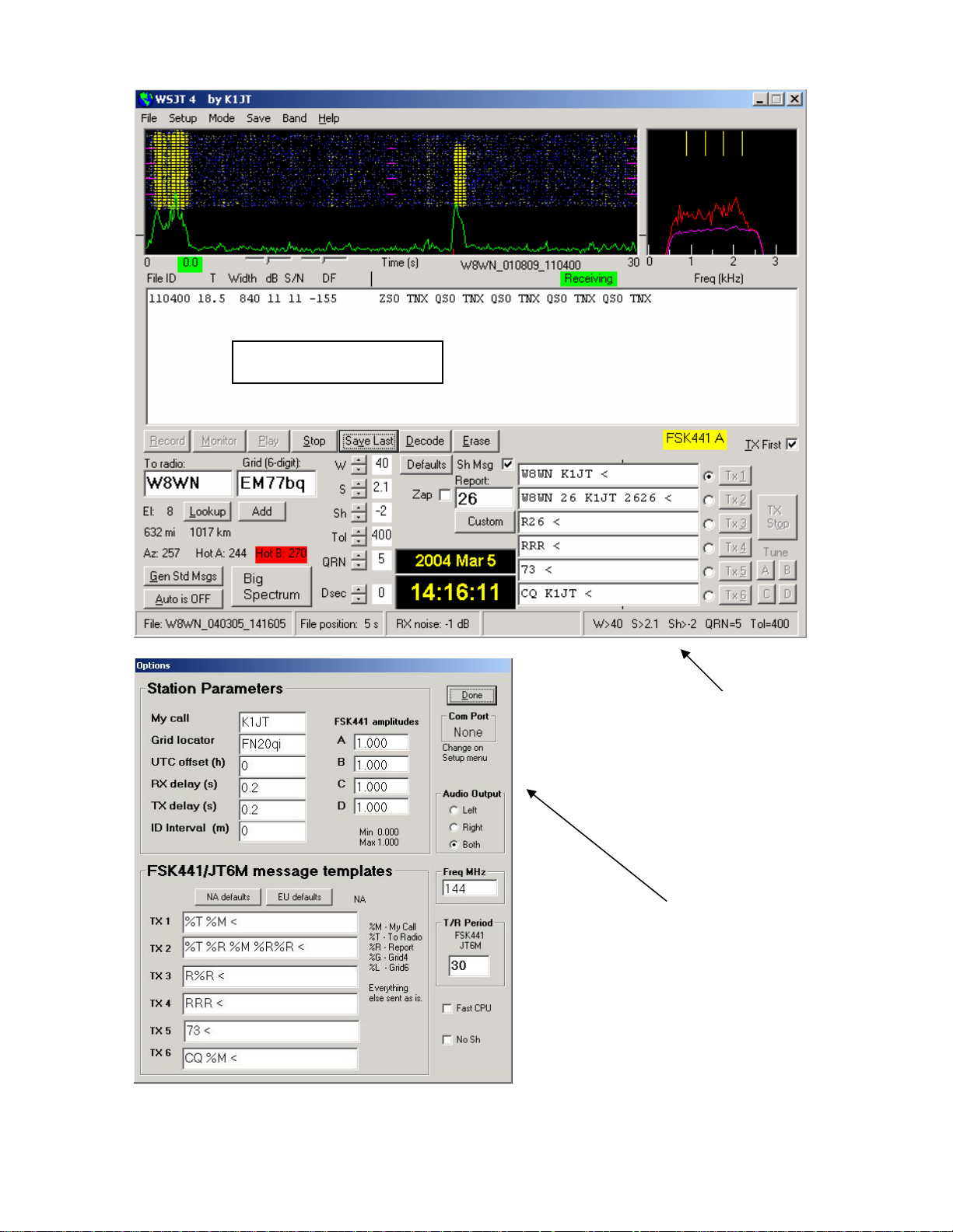
Decoded Text Box
Main Screen
FSK441A mode
Setup | Options
Screen
2
Page 3

Example Files
To gain some familiarity with the operation of WSJT, use the program to decode some
example files provided with the standard installation. Hit function key F7 to choose
FSK441A mode, and select Open from the File menu. Navigate to the
folder in your WSJT home directory and open the file recorded from W8WN. When this
file has been decoded, the top of your screen should look like the picture on page 2. With a
speaker or headphones connected to the soundcard output, listen to the recording by clicking
the Play button. You will hear static crashes at the beginning of the file and a moderately
strong ping from W8WN about 18 seconds later. Try clicking around the ping with both left
and right mouse buttons, and observe the decoded text that appears. Click the Big
Spectrum button to see what these signals look like on the large waterfall display. Click
Erase on the main screen to clear the text and graphical areas.
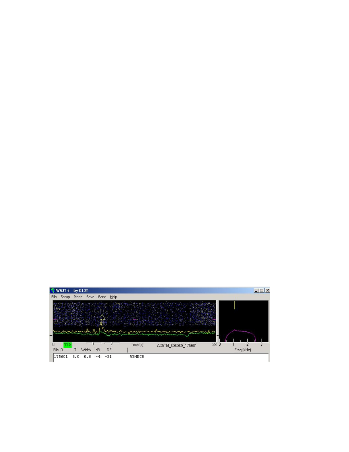
Next, select JT6M from the Mode menu and open the sample file from AF4O. Nothing
decodes automatically in this file—the signal is very weak—but try right-clicking on the
green line at about t = 12.9 s, as displayed on the green label at lower left of the plot area.
You will find that AF4O was calling K1JT. Try listening to this file: the signal is audible
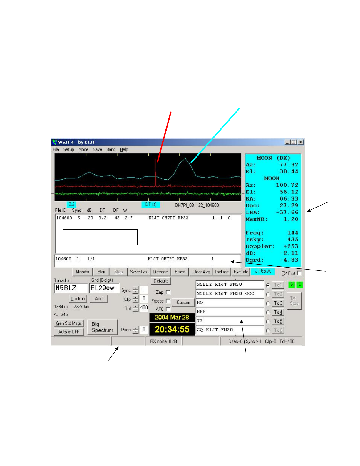
some of the time, but only barely. Finally, switch to JT65A mode and open the recording
from OH7PI. The graphics window and decoded text boxes on your screen should look like
the picture on page 5. Listening to this file, you will hear only random noise. OH7PI’s 144
MHz EME signal was much too weak for CW communication at this time, but he was solid
copy in JT65.
RxWav\Samples
Adjusting Signal Levels
1. Turn on your radio and tune it to a clear frequency so that only background noise is sent
to the sound card.
2. Press F9 to select the EME Echo mode.
3. Select Setup | Adjust RX Volume control to bring up the sound card input mixer.
4. Click Measure to start a sequence of noise measurements
5. Adjust a slider on the audio mixer and/or your receiver gain control(s) so as to bring the
signal level close to what WSJT calls “0 dB”. The signal level is displayed numerically
and illustrated by a green line in the plot area. The green curve should be approximately
aligned with tick marks on the left and right border.
6. Press F7 to enter FSK441A mode.
7. Click Record to start a receiving period. The program will record noise for 30 seconds
and then attempt to decode it. This should produce a jagged green line in the large plot
area, along with a waterfall-style spectrogram. The green line is a graph of received
noise power vs. time. The waterfall is a time vs. frequency spectrogram in which
frequency increases upward, time to the right.
8. Select Setup | Adjust TX Volume control to bring up the sound card output mixer.
9. Turn off your final amplifier (if any). Click one of the four Tune buttons A, B, C, or D
to be sure that T/R switching works and an audio tone is sent from the computer to your
radio.
10. Adjust the slider on the audio mixer to get the proper audio signal level for your
transmitter. Watch the transmitter power output while sending each of the four tones A,
B, C, and D. Variations of 10% or even 20% among the four tones are acceptable, but
50% differences will degrade your signal. You may find it useful to experiment with the
setting of a speech processor or ALC control.
3
Page 4
Basic Operating Instructions
Note: further details on commands in boldface may be found in the alphabetical list starting
on page 15.
WSJT uses timed intervals of transmission and reception. By convention FSK441 and
JT6M use 30 s periods, while JT65 always uses 60 s intervals. To prepare for making a
QSO, enter the other station’s callsign in the To radio box and click Lookup and Gen Std
Msgs to generate a sequence of commonly used messages. If Lookup does not find the
callsign in the database file
Decide whether you or the other station will transmit first, and check or uncheck TX First
appropriately. Click Auto to start an automatic sequence of transmission and reception
intervals.
At the end of each receiving period, WSJT displays various properties of a received signal
graphically. A green line illustrates signal strength vs. time, and other lines or images
display spectral information and synchronization results, depending on the mode. Decoded
text appears in the large box near center screen. Refer to the pictures on pages 2, 4, and 5
for examples in the FSK441, JT6M, and JT65 modes.
When an FSK441 or JT6M reception period has finished the program looks for signal
enhancements produced by short-lived reflections from meteor trails. You can often hear
such “pings” when they occur, and they can be seen as spikes on the green line and brighter
colors in the waterfall spectrum. One or more lines of decoded text may result from each
ping. By clicking on the green line with the mouse, you can force decoding of a particular
spot in a record.
CALLSIGN.TXT, you may enter the grid locator manually.
WSJT attempts to compensate for relative mistuning between transmitting and receiving
stations. By default the frequency search range is ±400 Hz (±600 Hz in JT65). You can
reduce the range by setting the value of Tol (for “tolerance”) to a lower value. Several other
decoding parameters can be adjusted, as well. In FSK441 mode W sets the minimum width
and S the minimum strength (in dB) for acceptable pings. Adjustments can be made at any
time by clicking on spinner controls next to the parameter labels, and all parameters can be
reset to default values by clicking the Defaults button.
JT6M
mode
In addition to the green line for overall signal strength, JT6M produces a yellow line
showing the detected strength of a synchronizing tone. JT6M attempts to decode both
individual pings and an “average message” based on the entire transmission (or selected
portions thereof). An average message is flagged with an asterisk at the right end of the text
line. Clicking with the left mouse button decodes a 4 s block of data near the mouse pointer,
while the right button decodes a 10 s segment. You can also drag the mouse pointer with the
4
Page 5
button down to select any desired region. As in FSK441, with marginal signals you should
(
(
)
experiment as necessary for best decoding. JT6M can work with signals many dB weaker
than those required for FSK441. You will sometimes find that clicking on a smooth green
line, even where nothing was heard and nothing can be seen, causes callsigns or other
information to pop up out of the noise.
Sync tone detected
at DF=43 Hz
red line
Time synchronization
at DT = 1.9 s
blue line)
DF: –600 –400 –200 0 200 400 600 Hz
DT: –1 0 1 2 3 4 5 s
T: 0 10 20 30 40 50 60 s
Graphics Window
Sun/Moon
Data
Decoded Text Box
TX Messages
Main Screen
JT65A mode
JT65 requires tight synchronization between transmitter and receiver, so in this mode the
only way to initiate a transmission or reception interval is by toggling Auto to ON. As in
other WSJT modes, an incoming signal is analyzed after a full receiving sequence is
complete. The resulting graphical display includes red and blue lines along with the green
line. The additional curves summarize the program’s attempts to synchronize with the
Average
Text Box
5
Page 6

received signal, a necessary step toward decoding the message. Proper synchronization is
indicated by a sharp upward spike in the red curve and a broader peak on the blue curve.
Horizontal locations of the peaks correspond to the frequency and time offsets, DF and DT,
between transmitter and receiver. EME QSOs have propagation delays of about 2.5 s and
can have significant Doppler shifts. Along with clock and frequency errors, these effects
contribute to the measured values of DT and DF.
Message Formats
Standard messages in FSK441 and JT6M are generated with the aid of templates defined on
the Setup | Options screen (see p. 2). Default templates are provided conforming to
standard practice in North America and Europe, and you can edit the templates to suit your
own requirements. Normal FSK441 and JT6M messages can contain any arbitrary text up
to 28 characters. The supported character set is
0123456789ABCDEFGHIJKLMNOPQRSTUVWXYZ.,/#?$ plus the space character.
FSK441 provides a special shorthand format to transmit a few simple messages in a highly
efficient way. Check Sh Msg to activate shorthand messages. The supported messages are
R26, R27, RRR, and 73. FSK441A sends pure tones at 882, 1323, 1764, or 2205 Hz to
convey them, while FSK441B and C use alternating two-tone sequences with the lower tone
at 861 Hz and the upper at 1206, 1550, 1895, or 2240 Hz.
JT65 messages are more constrained and must have one of three basic formats:
1. Four alphanumeric fields with specific contents as described below.
2. Any arbitrary text, up to 13 characters
3. Special shorthand messages ATT, RO, RRR, and 73
The four fields of a type 1 message usually consist of two legal callsigns, an optional grid
locator, and the optional signal report OOO. CQ or QRZ can be substituted for the first
callsign, and CQ may be followed by a space and three digits to indicate a desired callback
frequency. If K1JT transmits on 144.140 and sends “CQ 113 K1JT FN20”, it means that he
will listen on 144.113 and respond there to any replies. A country prefix preceded by “/” or
a signal report of the form “–NN” or “R–NN” may be substituted for the grid locator. For
example, –24 might indicate that signals were received at –24 dB. The minus sign is
required, and NN must lie between 01 and 30. A list of supported country prefixes is given
in Appendix A. The following are all examples of legal messages of type 1:
F9HS K1JT F9HS K1JT FN20 F9HS K1JT FN20 OOO
F9HS K1JT OOO F9HS K1JT /KP4 F9HS K1JT /KP4 OOO
VK7MO K1JT –24 K1JT VK7MO R–26 CQ K1JT
CQ K1JT FN20 CQ 113 K1JT CQ 113 K1JT FN20
QRZ K1JT QRZ K1JT FN20
The JT65 shorthand messages are powerful because they can be decoded at signal levels
some 5 dB below those required for standard messages. They do not use tight time
synchronization, so they provide no information on DT. The ATT message (for
“Attention”) is intended to help two stations find each other before a normal QSO begins. If
a message starts with ATT, RO, RRR, or 73, the shorthand format will be sent. If it satisfies
the requirements for message type 1, the full message of up to 22 characters will be
compressed and sent. With any other entry, 13 characters of arbitrary text will be sent.
6
Page 7

Standard QSO Procedures
Difficult contacts become easier if you follow standard operating practices. For minimal
QSOs, the recommended procedure is as follows:
1. If you have received less than both calls from the other station, send both calls.
2. If you have received both calls, send both calls and a signal report.
3. If you have received both calls and a report, send R plus your signal report.
4. If you have received R plus signal report, send RRR.
5. If you have received RRR — that is, a definite acknowledgment of all of your
information — the QSO is officially complete. However, the other station may not
know this, so it is conventional to send 73s (or some other conversational
information) to signify that you are done.
Slightly different procedures may be used in different parts of the world, or in the different
operating modes. Typing the F5 key will cause WSJT to pop up a screen that reminds you
of the recommended procedures.
Select the message for your next transmission by clicking in the small circle to the right of
the message text. In the FSK441 and JT6M modes, and for shorthand messages in JT65,
you can switch messages while a transmission is in progress by clicking on one of the TX
buttons to the right of the circles.
Operating Hints
After every decoding attempt, WSJT displays its best estimate of a detected signal’s
frequency offset. The accuracy of these estimates is approximately ±25 Hz for FSK441
signals, ±10 Hz for JT6M, and ±3 Hz for JT65. Within these tolerances (and subject to the
stability of oscillators and the propagation path) you should see consistent numbers in the
DF column during any QSO producing usable signals.
In the FSK441 and JT6M modes, if DF lies outside the range ±100 Hz it will help to retune
your receiver to compensate. Do this with the RIT control, or by using split RX/TX VFOs.
In general you should not change your transmitting frequency during a QSO, since your
partner will be trying to tune you in at the same time.
JT65 is tolerant of frequency offsets up to ±600 Hz, and unless the “red spike” is close to
one edge of the plot area (see picture on p. 5), retuning with RIT is optional. However, note
that EME QSOs on bands above 432 MHz can have Doppler shifts of several kHz or more.
In such cases you will certainly need to use RIT or split VFOs in order to acquire the
received signal. Once the program has synchronized on a JT65 signal, it’s best to click on
the red spike, check Freeze, and reduce Tol to 100 Hz or less. In subsequent decodings,
WSJT will search a range of frequencies only ±Tol Hz around the DF selected by clicking
on the red spike.
Question marks in displayed JT65 text lines indicate “OOO” and shorthand messages about
which there could be some doubt. These occur when the OOO flag has apparently been
found but the full message text not decoded, or when a probable shorthand message is
detected but you have not yet checked Freeze and reduced Tol to 100 Hz or less. Operator
skill is required in order to make the best possible use of JT65 shorthand messages. Visual
aids to decoding shorthand messages “by eye” are provided if you click on the sync-tone
frequency in the Big Spectrum display.
7
Page 8

You will need a method of setting your computer clock to an accuracy of one second or
better, and keeping it set. Many operators use an internet clock-setting program, while
others use a GPS or WWVB receiver.
Solar and Lunar Data
The light blue text box in JT65 and EME Echo mode presents data for tracking the moon,
measuring sun noise, tuning your receiver, and evaluating EME path losses. The information
includes azimuth and elevation (Az and El) for the sun and those quantities plus right
ascension (RA), declination (Dec), and local hour angle (LHA) for the moon. All
coordinates are in degrees except for RA, which is given in hours and minutes. The moon’s
semi-diameter (SD) is given in arc minutes, and Doppler shift for the band in use in Hz.
Since two-way Doppler shift depends on the other station’s location as well as your own, the
Doppler field is blank if the Grid box is empty. In EME Echo mode, the displayed
Doppler is your own self-echo value. Tsky gives the galactic background temperature in
the direction of the moon, scaled to the operating frequency, and dB the added signal loss at
the moon’s present distance, relative to perigee. Dgrd is an estimate of the total signal
degradation in dB, relative to the best possible time when the moon is at perigee and in a
cold part of the sky. Click with the mouse anywhere in the light blue text box to see the
local coordinates (Az and El) of the moon at the DX station’s location and the maximum
non-reciprocity of the EME path, in dB. Click again to toggle back to the normal display.
Distinctions between the Submodes
Messages are encoded differently in the three FSK441 submodes, so a transmission in one
mode must be decoded using the same mode. FSK441A uses a zero-redundancy code in
which characters are transmitted with three successive tones, each at one of four assigned
frequencies. The FSK441B and C modes use sequences of four and seven tones,
respectively, with the additional information providing error-correcting capabilities.
FSK441B can correct any single error in the four symbols that make up a character, while
FSK441C can correct up to three errors in seven symbols.
JT65 transmits messages using 65-tone frequency-shift keying at 2.7 baud. The lowest tone
at 1270.5 Hz is used to establish time and frequency synchronization; it is switched on for
half of the time, according to a pseudo-random on-off pattern. The remaining tone intervals
carry the user message, using a Reed-Solomon code for forward error correction. The three
JT65 submodes all use the same code and modulation scheme, but the spacing between
tones is different—approximately 2.7, 5.4, and 10.7 Hz for modes A, B, and C, respectively.
A transmission in one submode must be received in the same submode. If the equipment
and propagation path are stable enough that the measured width of the sync tone is
consistently 4 Hz or less, JT65A will be about 1 dB more sensitive than mode B and 2 dB
more sensitive than C.
Shorthand JT65 transmissions consist of alternating tones, each lasting 1.486 s. The lower
of the two frequencies is always at the sync-tone frequency, 1270.5 Hz, and the separation
between tones is given in the following table:
Message JT65A JT65B JT65C
ATT 26.9 Hz 53.8 107.7 Hz
RO 53.8 107.7 Hz 215.3
RRR 80.8 161.5 323.0
73 107.7 215.3 430.7
8
Page 9

EME Echo Mode
EME Echo mode (see picture on next page) is designed to help evaluate the performance of
your station for moonbounce communications. Activate it from the Mode menu or by
pressing function key F9. Aim your antenna at the moon, pick a clear frequency, and toggle
the Auto button to ON. The program will then start cycling through the following loop:
1. Transmit a fixed tone for 2.0 s
2. Wait about 0.5 s for start of return echo
3. Record the received signal for 2.0 s
4. Analyze, average, and plot the results
5. Repeat from step 1
At the start of each transmission the frequency of the transmitted tone is offset randomly
around a nominal value of 1500 Hz. A number in the text box labeled Dither (Hz) controls
the magnitude of the random offset. The observed spectrum of each echo is shifted by the
dither amount before being accumulated into the average. This procedure is very effective
in minimizing the impact of birdies in the receiver passband. In the average spectrum, a
fixed-frequency birdie is smeared out over a wide range while the desired signal remains
sharply defined.
EME Echo mode
Two curves appear in the graphical area after each T/R cycle, each one representing the
spectrum of received power over a 400 Hz range, centered on the expected echo frequency.
The blue (lower) curve is a reference spectrum that you can use to be sure you have chosen a
birdie-free passband. It is aligned to remove the Doppler shift computed at the start of the
run and not subsequently adjusted for changes in Doppler or the programmed dithering of
transmitted frequency. Stable birdies therefore stay fixed in the blue curve, making them
easy to recognize. The red curve displays the average echo signal, adjusted to correct for
changing Doppler shift and for the programmed frequency dithering. Your echo should
appear as a narrow spike near the middle of the red curve, close to DF = 0.
9
Page 10

Information in the text box gives the number N of completed echo cycles, the average Level
of receiver background noise in dB, the average echo strength Sig in dB, its measured
frequency offset DF in Hz (after correction for Doppler shift), its spectral Width in Hz, and
a relative quality indicator Q on a 0–10 scale. Background noise level is given with respect
to the nominal “0 dB” level used for all WSJT modes. Signal strength is measured in dB
relative to the noise power in the full receiver passband, nominally 2500 Hz. Q = 0 means
that an echo has not been detected or is very unreliable, in which case the values of DF and
Width are meaningless and Sig is an upper limit. Larger values of Q imply increasingly
believable echo measurements. If you can hear your own lunar echoes, you will see a large
spike in the red curve within a few seconds after toggling Auto ON. If your echoes are 15
to 20 dB below the audible threshold you should see a significant spike on the red curve
within a few minutes.
By default EME Echo mode assumes that your receiver and transmitter are tuned to the
same frequency. An on-screen box labeled RIT (Hz) allows you to inform the program of
any offset receiver tuning, for example to accommodate a large Doppler shift. Suppose you
are running a test on 23 cm and the predicted Doppler shift at the start of the run is –1400
Hz. In that case the 1500 Hz transmitted audio tone would be detected at 100 Hz, probably
well below the low-frequency cutoff in your receiver's passband. Use your transceiver's RIT
control to offset the receiver tuning by the predicted Doppler shift or a nearby rounded
value, and enter this offset in the RIT box before starting the echo measurement. The
program will track subsequent Doppler changes up to about 800 Hz, if necessary, without
any further adjustments. Your echo should appear near the center of the red curve, as usual.
You won't need to use the RIT feature on 6 or 2 meters, where Doppler shifts are much
smaller and echoes always fall within the transceiver's SSB passband.
The frequency of a valid echo should be well defined and stable. If you click Clear Avg to
start a new measurement, the echo signal (the red spike) should build up again at the same
DF. To be absolutely sure that you are seeing you own echo, offset your transmitter
frequency by a known amount, say 50 Hz, while holding the receiver frequency constant. A
valid echo will shift by the same 50 Hz.
Measure Mode
A button labeled Measure provides a means for measuring relative noise power from your
receiver. Click it and your system will record audio for one second, compute the level of
noise power, and display the result in dB relative to WSJT’s standard level. This cycle is
repeated every 2 seconds, with the results plotted as a green line and summary data
displayed in the large text box.
If the file DECODED.CUM has been activated from the File menu, data will be written into
that file as well, tagged with the Modified Julian Date on which you made the
measurements. You can use this mode to measure sun noise, antenna temperature, ground
noise, preamp gain, and a host of other useful quantities relative to a chosen reference level.
Be sure to disable the receiver AGC if you intend to use the mode for quantitative
measurements. It would also be wise to make some test measurements (for example, using a
calibrated attenuator) to confirm that the reported dB readings are reliable in your system as
configured.
10
Page 11

Measure mode, with
preamp turned
on and off repeatedly
EME Calc
Clicking the button labeled EME Calc at the lower left of the Echo-mode screen will pop up
a utility program for predicting the strength of your echoes from the moon. Enter the
requested quantities for your station and click Compute; if you enter parameters for a DX
station as well, you will see the maximum strengths for both station’s self-echoes and for
each signal at the other location. Clicking Now will enter the frequency of the active band
as specified on the Setup | Options form, and the sky background temperature at that
frequency. You can Save a set of parameters to a file, and Load a saved parameter set at
some later time.
EME Calc
Predicted echo strengths assume that your specified parameters are reliable, everything is
working right, and Faraday rotation is cooperating (if relevant). There are many reasons
why your actual echo strength at a given time may be less than the predicted value—and a
few reasons why it might (briefly) be slightly greater.
Amplifier Considerations
WSJT sends a single-frequency sine wave at any instant when it is transmitting. Except
during station identification, there is no “key up” time; signal amplitude is constant, and one
tone changes to the next one in a phase-continuous manner. As a result, WSJT does not
require a high degree of linearity in your power amplifier. You can use a class C amplifier
without generating unwanted sidebands or splatter. Please note that full amplitude
11
Page 12

transmissions lasting 30 seconds or longer will put more stress on your final amplifier than
SSB or CW operation. If this would cause the amplifier to overheat, you should take
appropriate action: reduce power or add another cooling fan or blower.
Menus and the Setup | Options Screen
File
Open: read and decode a previously recorded file stored on disk. The file must be a
standard wave file recorded in 8-bit monaural format with 11025 Hz sampling.
Open Next in Directory: read and decode the next file after one already opened.
Decode All Files in Directory: sequentially read and decode all wave files following
the one already opened.
Delete files in RxWav: delete all
Save text in file DECODED.CUM: append decoded text to a file named
DECODED.CUM in the WSJT installation directory.
Delete file DECODED.CUM: erase the cumulative text file.
Exit: terminate the program
*.WAV files in the RxWav subdirectory.
Setup | Options (see screen picture on p. 2)
My call: Enter your callsign
Grid locator: Enter your 6-digit grid locator
UTC offset: your timezone offset from UTC, in hours. Enter a negative value if you are
east of Greenwich.
RX delay: enforce specified delay between end of transmission and start of next
recording.
TX delay: enforce specified delay between activation of PTT line and start of first audio
tone sent to transmitter.
ID Interval: set time in minutes between automatic station identifications. A value of
zero disables the automatic identification. To use this feature you must provide an audio
file named
using any desired mode, e.g., voice or CW. (See Generate ID.WAV).
ID.WAV in the WSJT home directory. The file can identify your station
12
Page 13

NA/EU Defaults: insert default templates for generating standard FSK441 and JT6M
messages. The templates can be edited, for example to append a suffix or prefix to a
callsign, or to properly format a contest exchange. For example, if G4FDX changes the
template for message TX1 to read “
appear in the box for TX message 1 when he presses Gen Std Msgs to call K1JT.
FSK441 Amplitudes: set relative voltage to be generated for each FSK441 tone. If
necessary, one or more of these numbers can be decreased from the nominal 1.0 to
compensate for nonuniform frequency response in your TX audio system.
Audio output: select which audio channel carries signal from the sound card to the
radio: Left, Right, or Both.
Freq MHz: nominal frequency in MHz, used for computing Doppler shifts and sky
background temperatures. (See also Band menu.)
T/R Period: set length of T/R intervals for FSK441 and JT6M modes, in seconds.
Fast CPU: decode JT65 signals immediately after a recording has finished. Check this
box only if your computer is fast enough to allow decoding in 5 seconds or less. It
permits you to see a decoded message before your next transmission begins.
No Sh: disable all decoding of shorthand messages in FSK441.
%T W9/%M”, the message “K1JT W9/G4FDX” will
Other Setup Items
Set COM port: set number of the COM port that will activate T/R switching. To
disable COM port T/R switching, enter 0.
Generate ID.WAV: create a CW wave file in the WSJT home directory with “My call”
sent at 25 WPM, 440 Hz.
DTR, RTS: select the serial-port signal line that will control your T/R switching
sequence.
Adjust RX/TX Volume controls: display sound mixer controls.
Alternate graphical pointer: use “arrow” instead of “crosshairs” as the mouse’s
graphical pointer.
13
Page 14

Alternate PTT Logic: activate slightly different program logic for controlling your T/R
switching via the COM port. (A few combinations of hardware and operating system
drivers seem to work better with this option checked.)
Tx Mute: mute the transmitter. Use with Auto ON to monitor one side of a QSO.
Enter new “To radio” callsign: clear the To radio and Grid boxes in preparation for
new entries.
Tx Stop forces Auto OFF: if this item is checked, clicking TX Stop during a
transmission will toggle Auto to OFF.
Mode
Select desired operating mode from this menu.
Save
Save Decoded: save any files producing decoded text in subdirectory RxWav under
your WSJT home directory.
Save All: save all recorded files in subdirectory RxWav of your WSJT home directory.
Band
Select your operating band from displayed list. The selected frequency is used for
computing EME Doppler shifts and sky background temperatures.
Help
Help: displays a brief message urging you to download and read the WSJT 4.6 User’s
Guide (the manual you are reading now).
About WSJT: displays version and copyright information.
Which message should I send? Choosing this item (or using shortcut F5) will pop up a
text box with reminders about the standard message sequences used for minimal QSOs
with FSK441, JT6M, and JT65.
14
Page 15

Alphabetical List of On-Screen Controls
Note: some controls are visible only in certain operating modes.
Add: causes the displayed callsign and grid locator to be added to the database file
CALLSIGN.TXT. If an entry for this callsign already exists, you will be asked if you want to
replace it.
AFC: activate automatic frequency control in JT65 decoding algorithm.
Auto: toggles ON or OFF timed sequencing of transmit and receive periods.
Big Spectrum: display large waterfall spectrogram for most recently decoded file. Time
increases from top to bottom, frequency from left to right. This display can help you to
identify different types of signals and noise, distinguish wanted signals from birdies, etc.
Brightness: adjust brightness of waterfall spectrogram (FSK441 and JT6M only; slider
below large graphics area). Click Decode to see effect of change.
Clear Avg: erase text in average message box, and clear message accumulator.
Clip: normally set to zero. Increase its value to 1, 2, or 3 to apply soft, moderate, or hard
clipping to a signal before attempting to decode its message. May be useful to reduce the
effects of static crashes, etc.
Contrast: adjust contrast of waterfall spectrogram (FSK441 and JT6M only; slider below
large graphics area). Click Decode to see the effect of a change.
Custom/Standard Texts: toggles between two sets of TX messages. Custom texts can be
used to store messages such as grid locator or contest information.
Decode: analyze most recently recorded or opened file, perhaps after one or more decoding
parameters (such as Freeze, Tol, Zap, AFC, or Clip) have been changed.
Defaults: reset parameters W, S, Sh, Sync, Clip, Tol, and QRN to default values.
Dsec: adjust UTC clock reading in ±1 s increments to manually resynchronize with UTC or
with your QSO partner’s computer. (In general, it is best to keep the Windows clock set
accurately and Dsec set to zero.)
EME Calc: activate the EME signal-level calculator.
Erase: clear all information in main text box and graphical areas.
Exclude: remove most recent recording from the average message accumulator. Use this
option when you are sure that the program has synchronized incorrectly (for example,
because DF and/or DT differ substantially from expected values) and you wish to avoid
contaminating the average message with bad data.
Freeze: search only frequencies within ±Tol Hz of target DF set by clicking on red spike.
Gen Std Msgs: generate standard messages; also reset TX message to 1 and Tol to 400 Hz.
Include: if signal level is greater than –32 dB, add most recent recording to average
message accumulator even if Sync is less than stated threshold.
Lookup: search database file
CALLSIGN.TXT for entry in To radio. If callsign is found, the
station's grid locator is retrieved and used to calculate distance, azimuth, elevation, and
Doppler shift.
15
Page 16

Measure: initiate a series of noise power measurements.
Monitor: start a series of recordings, perhaps to monitor a calling frequency or to copy two
other stations engaged in a QSO.
Play: play most recently decoded file through sound card speaker output. This button
functions much like the “Play” button on a cassette recorder.
QRN: adjust to higher values (default=5) to suppress false decodings caused by
atmospheric noise.
Record: start recording audio noise from radio. The program will record fo r the time
entered in T/R Period, or until you press Stop. If Auto is ON, recording will stop when the
present T/R interval is finished; the data will then be plotted and decoded. This control
works much like the “Record” button on a cassette recorder.
S: set minimum increase in signal that will be accepted as a ping.
Save Last: save most recently recorded file. (See also Save Decoded and Save all, on the
Save menu).
Sh: set minimum strength in dB of an acceptable FSK441 shorthand message.
Sh Msg: enable transmission of FSK441 shorthand messages R26, R27, RRR, and 73.
Stop: terminate a Record, Monitor, or Play operation. This control functions much like
the “Stop” button on a cassette recorder.
Sync: set synchronizing threshold (default=1) for the JT65 decoder.
Tol: set decoder tolerance (in Hz) to frequency offsets. When DF has been established and
reduced to a small value by retuning the receiver, decrease the value of Tol to reduce the
probability of false decodings.
Tune A, B, C, D: generate steady tones at one of the four standard FSK441 frequencies
882, 1323, 1764, or 2205 Hz.
Tx 1–6: transmit selected message. Transmission will continue until the end of the present
TX sequence or, if Auto is OFF, for the duration listed in the T/R Period box.
TX First: check this box if you want to transmit during the first period of the timed T/R
cycle. Uncheck it if your QSO partner is transmitting in the first period. In this context,
“first” is defined as transmitting during the first T/R interval of an hour.
TX Stop: terminate a transmission in progress.
W: set the minimum width of pings considered for automatic decoding.
Zap: filter out birdies (narrowband signals of approximately constant amplitude) before
attempting to decode.
Main Screen Text Boxes
Average Text: displays average messages in JT65 mode.
Decoded Text: displays decoded messages and other signal information.
Dither (Hz): sets maximum random offset applied to transmitted tones in Echo mode.
16
Page 17

Grid: after a successful Lookup, displays the six-digit grid locator of the callsign in the To
radio box. You can also enter a grid locator manually. If only four digits of the locator are
known, add a space.
Report: enter the signal report you wish to send to the other station, then click Gen Std
Msgs.
RIT (Hz): your receiver RIT setting in Hz.
Status Bar: panels at the bottom of the WSJT screen for displaying information such as file
name, file position, RX audio level, and decoding parameters.
Sun/Moon Data: current coordinates of sun and moon and EME path information. Click
anywhere in this box to display lunar coordinates for the DX station and MaxNR, the
maximum non-reciprocity of the EME path (caused by spatial polarization and Faraday
rotation). Click again to toggle back to the normal display.
Tavg (min): sets averaging time in EME Echo mode.
To radio: callsign of station being called. Text entered in this box becomes leading part of
recorded file names.
Appendix A: Supported Country Prefixes
If you are operating under the licensing authority of another nation, you can substitute the
portable country prefix (preceded by “/”) for your grid locator in the standard JT65 type 1
message. The supported three-character country prefixes are listed below:
1A 1S 3A 3B6 3B8 3B9 3C 3C0 3D2 3DA 3V 3W 3X 3Y 4J
4L 4S 4U1 4W 4X 5A 5B 5H 5N 5R 5T 5U 5V 5W 5X
5Z 6W 6Y 7O 7P 7Q 7X 8P 8Q 8R 9A 9G 9H 9J 9K
9L 9M2 9M6 9N 9Q 9U 9V 9X 9Y A2 A3 A4 A5 A6 A7
A9 AP BS7 BV BV9 BY C2 C3 C5 C6 C9 CE CE0 CE9 CM
CN CP CT CT3 CU CX CY0 CY9 D2 D4 D6 DL DU E3 E4
EA EA6 EA8 EA9 EI EK EL EP ER ES ET EU EX EY EZ
F FG FH FJ FK FM FO FP FR FT5 FW FY H4 H40 HA
HB HB0 HC HC8 HH HI HK HK0 HL HM HP HR HS HV HZ
I IG9 IS IT9 J2 J3 J5 J6 J7 J8 JA JD JT JW JX
JY K KG4 KH0 KH1 KH2 KH3 KH4 KH5 KH6 KH7 KH8 KH9 KL KP1
KP2 KP4 KP5 LA LU LX LY LZ M MD MI MJ MM MU MW
OA OD OE OH OH0 OJ0 OK OM ON OX OY OZ P2 P4 PA
PJ2 PJ7 PY PY0 PZ R1F R1M S0 S2 S5 S7 S9 SM SP ST
SU SV SV5 SV9 T2 T30 T31 T32 T33 T5 T7 T8 T9 TA TA1
TF TG TI TI9 TJ TK TL TN TR TT TU TY TZ UA UA2
UA9 UK UN UR V2 V3 V4 V5 V6 V7 V8 VE VK VK0 VK9
VP2 VP5 VP6 VP8 VP9 VQ9 VR VU VU4 VU7 XE XF4 XT XU XW
XX9 XZ YA YB YI YJ YK YL YN YO YS YU YV YV0 Z2
Z3 ZA ZB ZC4 ZD7 ZD8 ZD9 ZF ZK1 ZK2 ZK3 ZL ZL7 ZL8 ZL9
ZP ZS ZS8
17
Page 18

Further Reading
1. A separate WSJT 4.6 Technical Manual (in preparation) provides technical
specifications and details on how the WSJT modes work. The Technical Manual
will be posted at
http://pulsar.princeton.edu/~joe/K1JT, the WSJT home
page, when available.
2. In the meantime, technical information can be found in the Version 3.0 WSJT User’s
Guide and Reference Manual, which is still available at
http://pulsar.princeton.edu/~joe/K1JT/WSJT300.PDF.
3. The first WSJT mode, FSK441, was described in QST for December 2001, in an
article starting on p. 36.
4. JT44, a predecessor to the JT65 mode, was described in QST for June 2002 in “The
World Above 50 MHz,” p. 81.
Acknowledgments
An earlier version of this manual was co-authored with Andy Flowers, K0SM. I started over for the
current version, but many remnants of Andy’s hard work remain.
Bob McGwier, N4HY, goaded me into learning something about error-correcting codes, and Phil
Karn, KA9Q, helped me to understand some of their subtleties. Particular thanks are due to Ralf
Koetter and Alexander Vardy, authors of a research paper entitled “Algebraic Soft-Decision
Decoding of Reed-Solomon Codes.” This paper introduced me to the powerful decoding algorithm
now used in the JT65 modes. Through their company CodeVector technologies, Koetter and Vardy
granted a license to adapt their computer code, which is protected under United States patent
6,634,007, for noncommercial purposes within WSJT.
Many users of WSJT have contributed in important ways to the program’s development. Shelby
Ennis, W8WN, ran many dozens of schedules with me during the development FSK441 and JT6M,
and likewise Jack Carlson, N3FZ, for JT65. I learned that if Shelby and Jack can’t make a program
crash, most other users won’t be able to, either. Many other users—far too many to name
individually—provided extremely helpful criticisms, suggestions, and feedback. I should
particularly mention Lance Collister, W7GJ, who has never tired of saying, in effect, “surely you can
still get us one more dB!” All of these efforts are greatly appreciated.
18
 Loading...