

Pulsar EN54M-2A7, EN54M-5A7-17, EN54M-3A7-17, EN54M-2A7-17, EN54M-3A17-40 User Manual
...
USER MANUAL
EN
Edition: 2 from 04.04.2019
Supersedes the edition: 1 from 14.02.2019
Modules
EN54M series
v.1.0
Power supply modules for built-in
fire alarm systems and smoke
and heat control systems.

www.pulsar.pl EN54M RED POWER plus
2
GENERAL SAFETY RULES
Before installation, read the instruction manual to avoid errors that
can damage the device and give you an electric shock.
Before installation, cut off the voltage in the 230 V power-supply circuit.
To switch power off, use an external switch, in which the distance between the
contacts of all poles in the disconnection state is not less than 3mm.
The shock protection circuit shall be done with a particular care: the yellow and green
wire coat of the power cable should be connected to the terminal marked with
the grounding symbol on the PSU enclosure. Operation of the PSU without the
properly made and fully operational shock protection circuit is UNACCEPTABLE! It
can cause damage to the equipment or an electric shock.
The device should be transported without batteries. This has a direct impact on the
safety of the user and the device.
Installing and connecting the power supply must be carried out without batteries.
When connecting batteries to the power supply, pay particular attention to the correct
polarity. If necessary, it is possible to permanently disconnect the battery from the
power supply systems by removing the F
BAT
fuse.
The power supply is adapted to be connected to a power distribution network with an
effectively earthed neutral conductor.
Ensure a free, convection air flow around the enclosure. Do not cover the ventilation
openings.

www.pulsar.pl EN54M RED POWER plus
3
TABLE OF CONTENTS
1. PSU FEATURES. .................................................................................................................................... 4
2. FUNCTIONAL REQUIREMENTS OF POWER SUPPLY MODULES. ........................................ 5
3. TECHNICAL DESCRIPTION. ............................................................................................................. 6
3.1. GENERAL DESCRIPTION. ....................................................................................................................................................... 6
3.2. BLOCK DIAGRAM. ................................................................................................................................................................ 6
3.3. DESCRIPTION OF COMPONENTS AND POWER SUPPLY TERMINALS. ........................................................................................ 7
3.4. DIMENSIONS OF POWER SUPPLY MODULES. .......................................................................................................................... 8
4. INSTALLATION. ................................................................................................................................... 9
4.1. REQUIREMENTS. .................................................................................................................................................................. 9
4.2. INSTALLATION PROCEDURE. ................................................................................................................................................ 9
4.3. PROCEDURE FOR CHECKING THE POWER SUPPLY MODULE AT THE PLACE OF INSTALLATION. ............................................ 10
5. FUNCTIONS ......................................................................................................................................... 11
5.1. TECHNICAL OUTPUTS. ........................................................................................................................................................ 11
5.2. INPUT OF COLLECTIVE FAILURE: EXTI. ................................................................ .............................................................. 12
5.3. INDICATION OF THE ENCLOSURE OPENING - TAMPER. ..................................................................................................... 13
5.4. PSU OVERLOAD. ................................................................................................................................................................ 13
5.5. SHORT-CIRCUIT OF THE PSU OUTPUT. ............................................................................................................................... 13
5.6. ADDITIONAL MODULES. ..................................................................................................................................................... 13
5.6.1 Extending the number of PSU outputs - EN54C-LB4 and EN54C-LB8 fuse modules. ................................................ 13
5.6.2 Cooperation with electric actuators - EN54C-LS4 and EN54C-LS8 sequential modules. .......................................... 14
6. RESERVE POWER SUPPLY CIRCUIT. .......................................................................................... 15
6.1. BATTERY DETECTION. ....................................................................................................................................................... 15
6.2. PROTECTION AGAINST SHORT-CIRCUIT OF THE BATTERY TERMINALS. ............................................................................... 15
6.3. PROTECTION AGAINST REVERSE BATTERY CONNECTION. ................................................................................................... 15
6.4. DEEP DISCHARGE BATTERY PROTECTION UVP. ................................................................................................................. 15
6.5. BATTERY TEST. ................................................................................................................................................................ .. 15
6.6. MEASUREMENT OF THE RESISTANCE OF THE BATTERY CIRCUIT. ........................................................................................ 15
6.7. BATTERY TEMPERATURE MEASUREMENT. ......................................................................................................................... 15
6.8. STANDBY TIME. ................................................................................................................................................................. 16
7. TECHNICAL PARAMETERS. .......................................................................................................... 17
Table 4. Electrical parameters. ............................................................................................................................................ 17
Table 5. Mechanical parameters. ......................................................................................................................................... 18
Table 6. Safety of use. ........................................................................................................................................................... 18
Table 7. Recommended types and sections of installation cables. ....................................................................................... 18
8. TECHNICAL INSPECTIONS AND MAINTENANCE. .................................................................. 19

www.pulsar.pl EN54M RED POWER plus
4
Built-in power supply module
In accordance with standards: EN 54-4,
EN12101-10
27,6 V DC uninterruptible power supply
available versions with 2 A/3 A/5 A/10 A current
efficiencies
available versions with space for 7 Ah – 65 Ah
batteries
independently protected outputs AUX1 and AUX2
DIN rail mounting using additional EN54M-DIN1
bracket (optional equipment)
cooperation with EN54C-LB4 and EN54C-LB8 fuse
modules (optional equipment)
cooperation with EN54C-LS4 and EN54C-LS8
sequential modules (optional equipment)
optical indication – LED panel EN54M-LED (option)
high efficiency (up to 89%)
low level of voltage ripple
microprocessor-based automation system
measurement of the resistance of the battery circuit
automatic temperature-compensated charging
automatic battery test
two-stage battery charging process
accelerated battery charging
monitoring of the continuity of the battery circuit
monitoring of the battery voltage
monitoring of charging and maintenance of the
batteries
deep discharge battery protection (UVP)
battery overcharge protection
the LoB low battery voltage indication
battery output protection against short-circuit and
reverse connection
output voltage control
fuse monitoring of AUX1 and AUX2 outputs
relay output of collective failure ALARM
EPS relay output indicating 230 V power loss
the EXTi input of external failure
protections:
SCP short-circuit protection
OLP overload protection
OVP overvoltage protection
Surge protection
convection cooling (forced only in the EN54M-
10Axx)
warranty - 3 years from the production date
1. PSU features.

www.pulsar.pl EN54M RED POWER plus
5
Functional requirements
Requirements
according to
standards
Power supplies
EN54M series
Two independent power sources
YES
YES
External Power Supply failure indication
YES
YES
Two independent power supply outputs protected against short-circuit
YES
YES
Temperature-compensated battery charging
YES
YES
Measurement of the resistance of the battery circuit
YES
YES
Low battery indication
YES
YES
Recharging the battery to 80% of the rated capacity within 24 hours
YES
YES
Deep discharge battery protection
YES
YES
Short-circuit protection of battery terminals
YES
YES
Charging circuit failure indication
YES
YES
Short-circuit protection
YES
YES
Overload protection
YES
YES
Output of collective failure ALARM
YES
YES
EPS technical output
YES
YES
Low output voltage indication
-
YES
High output voltage indication
-
YES
Indication of power supply failure
-
YES
Overvoltage protection
-
YES
Input of an external failure indication EXTi
-
YES
2. Functional requirements of power supply modules.
Buffer power supply modules for fire alarm systems has been designed in accordance with the following
standards:
- EN 54-4:2001+A1:2004+A2:2007 Fire detection and fire alarm systems.
- EN 12101-10:2007 Smoke and heat control systems.
www.pulsar.pl EN54M RED POWER plus
6
Built-in power supply
module model
Battery
Continuous operation
Imax a
Instantaneous operation
Imax b
EN54M-2A7
EN54M-2A7-17
7,2 Ah
1,6 A
2 A
7÷20 Ah
1,2 A
EN54M-3A7-17
EN54M-3A17-40
7÷20 Ah
2,2 A
3 A
17÷45 Ah
1,2 A
EN54M-5A7-17
EN54M-5A17-40
EN54M-5A40-65
7÷20 Ah
4,2 A
5 A
17÷45 Ah
3,2 A
40÷65 Ah
2,4 A
EN54M-10A17-40
EN54M-10A40-65
17÷45 Ah
8,2 A
10 A
40÷65 Ah
7,4 A
3. Technical description.
3.1. General description.
The power supply modules are designed for mounting in an additional housing. In order to meet
the requirements of the EN54-4 + A1 + A2 and EN12101-10 + AC standards, the enclosure must be of
appropriate construction. IP30 protection class is required.
Buffer power supply modules has been designed for an uninterrupted supply of fire alarm systems,
smoke and heat control systems, fire protection equipment and fire automatics requiring stabilized voltage of
24 V DC (±15%). The power supplies are fitted with two independently protected AUX1 and AUX2 outputs,
which provide a voltage of 27,6 V DC and the total current efficiency depending on the version:
In case of power loss, the PSU switches to battery power, providing uninterruptible power supply.
The power supply modules units works with maintenance-free lead acid batteries made with AGM
technology or gel technology.
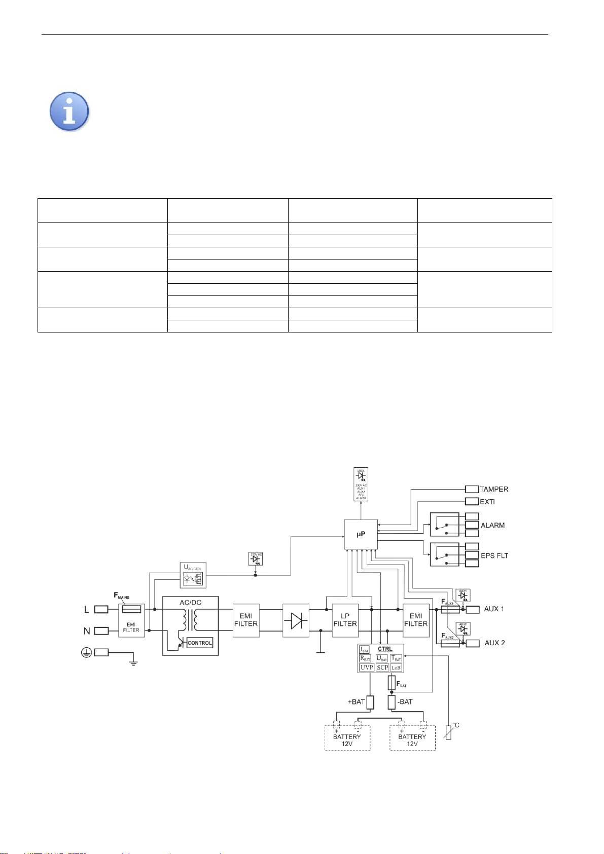
3.2. Block diagram.
The power supply modules has been manufactured based on a high-efficiency system of AC/DC
converter. Applied microprocessor circuit is responsible for the full diagnostics of the PSU parameters and
batteries. The figure below shows a flowchart of the power supply, along with selected functional blocks which
are essential for the proper functioning of the unit.
Fig. 1. Block diagram of the PSU module.
 Loading...