

Page 1

DIN 1220
v.1.0
DIN 12V/2A
DIN rail power supply unit.
EN
Edition: 1 from 28.05.2013
Supersedes edition: ---------------
Page 2
www.pulsar.pl DIN1220
2
CONTENTS:
1. Technical description.
1.1 General description
1.2. Block diagram
1.3. Description of components and connectors
1.4. Specifications
2. Installation.
2.1 Requirements
2.2 Installation procedure
3. Operation and use
4.1. Overload or short circuit of the PSU module output
4.2. Maintenance
1. Technical description
1.1 General description
The power supply unit is intended for the feeding of alarm system equipments, which require
12V DC. Their design enables simple changing of the output voltage, within the range of 12V÷15V DC, using a
potentiometer. The unit is protected against short-circuit and overload.The power supply units is protected
against short-circuit, overload and overvoltage.
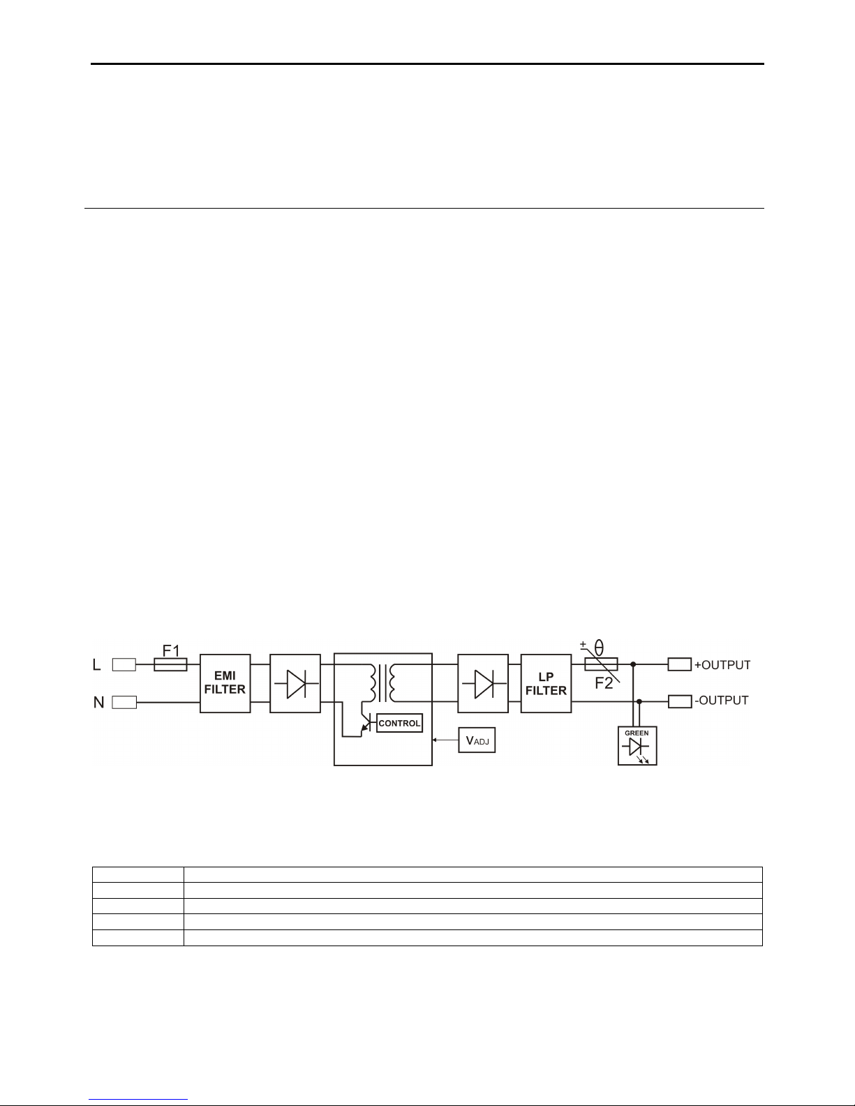
1.2. Block diagram.
Fig.1. Block diagram of the PSU .
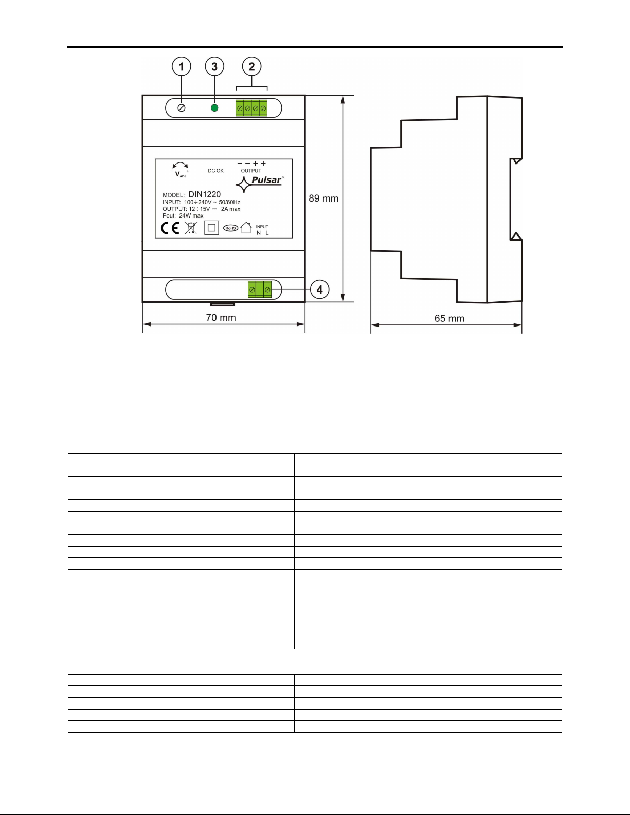
1.3. Description of components and connectors (Fig.2, tab.1).
Table 1. Description of PSU.
Element no. Description
[1] V
ADJ
potentiometer, DC voltage adjustment
[2] + OUTPUT - DC supply output
[3]
LED for DC voltage
[4] L-N - input voltage connectors 230 V AC
Features:
• power output 2A/12÷15VDC
• wide AC input voltage range 90÷264V
• high efficiency 85%
• LED optical signalisation
• protections:
• SCP short-circuit protection
• overvoltage protection
• overload protection (OLP)
• warranty – 2 year from the production date
Page 3
www.pulsar.pl DIN1220
3
Fig. 2. The view of the PSU.
1.4. Specifications:
- electrical specifications (tab.2)
- mechanical specifications (tab.3)
- operating specifications (tab.4)
Electrical specifications (tab. 2).
Supply voltage
90÷264V AC
Current consumption
0,3A@230VAC max.
PSU power
24W max.
Efficiency 85%
Output voltage
12V DC
Output current
2A
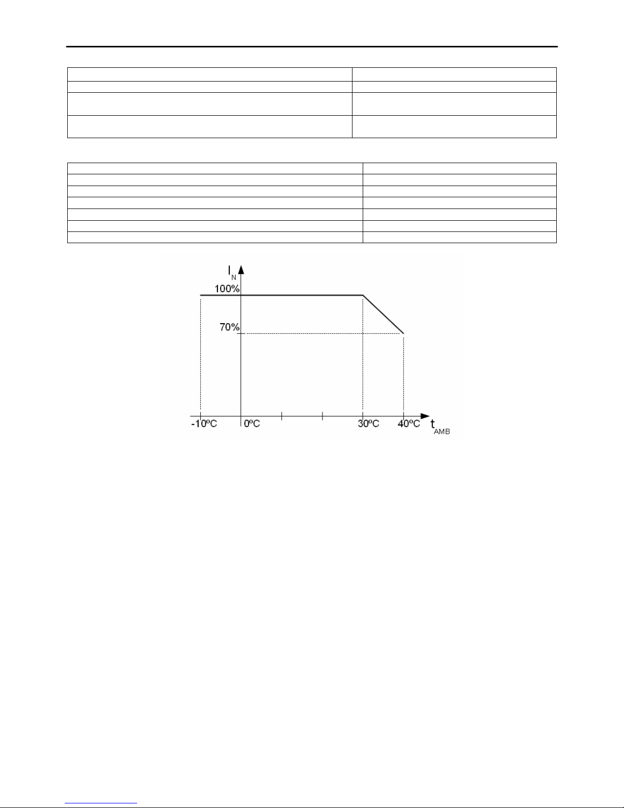
Output current t
AMB
<30°C
2 A -
refer to chart 1
Output current t
AMB
=40°C
1,4 A -
refer to chart 1
Voltage adjustment range
12 ÷15V DC
Ripple voltage 100mV p-p max.
Short-circuit protection SCP electronic,
automatic recovery
Overload protection OLP
110% ÷ 150% @25ºC of PSU module power current limitation with the PTC resettable fuse, manual
restart (failure requires disconnection of the DC output
circuit)
Surge protection varistors
LED indication: LED for DC voltage
Mechanical specifications (tab. 3).
Enclosure dimensions 70 x 89 x 69 (WxHxD)
Fixing on DIN TH35 rail
Net/gross weight 0,19kg/0,24kg
Enclosure ABS, RAL7035, light grey
Connectors Φ0,63÷2,50 (AWG 22-10)
Page 4
www.pulsar.pl DIN1220
4
Operation safety (tab.4)
Protection class PN-EN 60950-1:2007
II (
second)
Protection grade PN-EN 60529: 2002 (U) IP20
Electrical strength of insulation:
- between input input and output circuits of the PSU (I/P-O/P)
3000 V/AC min
Insulation resistance:
- between input circuit and output or protection circuit
100 MΩ, 500V/DC
Operating specifications (tab.5).
Operating temperature -10ºC...+40ºC
Storage temperature -20ºC...+60ºC
Relative humidity 20%...90%, without condensation
Vibrations during operation unacceptable
Impulse waves during operation unacceptable
Direct insolation unacceptable
Vibrations and impulse waves during transport PN-83/T-42106
Chart 1. Acceptable output current from the PSU depending on ambient temperature.
2. Installation.
2.1 Requirements
The PSU shall be mounted by a qualified installer with appropriate permissions and qualifications for
230V/AC installations and low-voltage installations (required and necessary for a given country). The device shall
be mounted in confined spaces, according to the environment class II, with normal air humidity (RH=90% max.
without condensation) and the temperature from -10°C to +40°C. The PSU shall work in a vertical positi on that
guarantees sufficient convectional air-flow through ventilating holes of the enclosure.
As the PSU is designed for a continuous operation and is not equipped with a power-switch, therefore an
appropriate overload protection shall be guaranteed in the power supply circuit. Moreover, the user shall be
informed about the method of unplugging (most frequently through separating and assigning an appropriate fuse in
the fuse-box). The electrical system shall follow valid standards and regulations.
The device should be installed in the metallic enclosure, distribution board (ICT cabinet) equipped with a
DIN TH35 rail (35 mm wide). In order to meet the UE requirements, the rules concerning: supply, development and
shielding ought to be followed- accordingly to the application.
2.2 Installation procedure
1. Install an enclosure, a distribution board or a cabinet and lead the cables through the cable ducts.
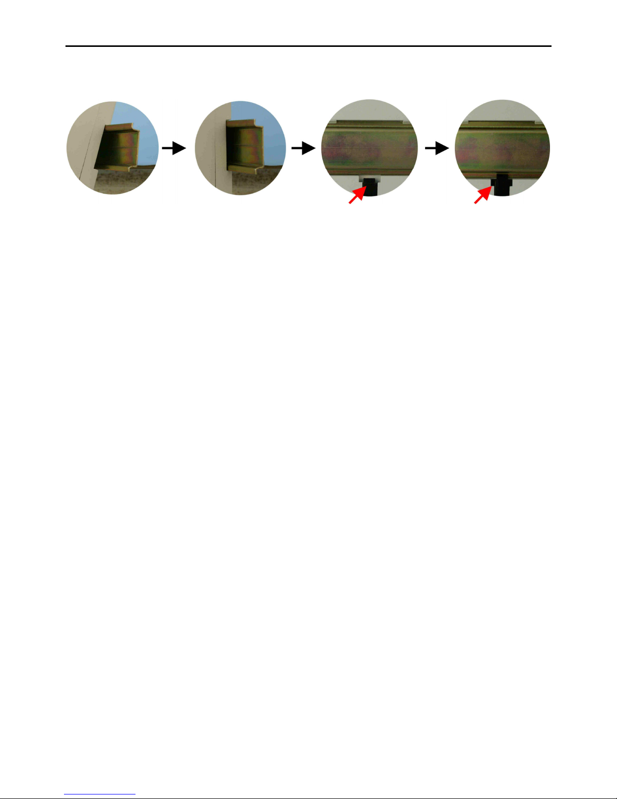
2. Install the PSU on the DIN rail: Mount the PSU onto the rail and block with a clip (Fig. 3)
3. Connect the receivers’ cables to the OUTPUT (+,-) terminals of the terminal block on the PSU module’s board.
4. Connect the 230VAC power leads (L, N).
5. Activate the ~230V/AC supply (the DC OK diode green should be permanently illuminated)
Page 5
www.pulsar.pl DIN1220
5
6. Check the output voltage PSU. If the value of the voltage requires adjustment, it should be set by the V
adj
potentiometer (12 ÷15V DC), monitoring the voltage at the output of the PSU.
7. Once the tests and operation control have been completed, the enclosure/cabinet can be locked.
Fig.3. Mounting on a DIN rail.
3. Operation and use.
3.1 Overload or short circuit of the PSU output (SCP on)
In case of overload, the output voltage is automatically shut off, and so is the LED indicator. The restoration
of the voltage takes place immediately after the failure (overload) is over.
3.2 Maintenance
Any and all maintenance operations may be performed following the disconnection of the PSU module from
the power supply network. The PSU module does not require performing any specific maintenance measures,
however, in case of significant dust rate, its interior is recommended to be cleaned with compressed air. In case of
fuse replacement, use a replacement of the same parameters.
Page 6

www.pulsar.pl DIN1220
6
WEEE MARK
According to the EU WEE Directive – It is required not to dispose of electric or electronic waste as
unsorted municipal waste and to collect such WEEE separately
.
GENERAL WARR
ANTY CONDITIONS
1. Pulsar K. Bogusz Sp.j. (the manufacturer) grants a two-year warranty for the equipment, counted from the device’s production
date.
2. The warranty includes free-of-charge repair or replacement with an appropriate equivalent (the selection is at the
manufacturer’s discretion) if the malfunction is due to the manufacturer, includes manufacturing or material defects, unless such
defects have been reported within the warranty period (item 1 ).
3. The equipment subject to warranty is to be brought to the place where it was purchased, or directly to the main office of the
manufacturer.
4. The warranty applies to complete equipment, accompanied by a properly filled warranty claim with a description of the defect.
5. Should the claim be accepted, the manufacturer is obliged to provide warranty repairs, at the earliest convenience, however not
later that within 14 days from the delivery to the service centre of the manufacturer.
6. The repair period mentioned in item 5 may be prolonged, if there are no technical possibilities to carry out the repairs, or if the
equipment has been conditionally accepted, due to the breaking warranty terms by the claimant.
7. All the services rendered by force of the warranty are carried out at the service centre of the manufacturer, exclusively.
8. The warranty does not cover the defects of the equipment, resulting from:
- reasons beyond the manufacturer's control,
- mechanical damage,
- improper storage and transport,
- use that violates the operation manual or equipment’s intended use
- fortuitous events, including lightning discharges, power failures, fire, flood, high temperatures and chemical agents,
- improper installation and configuration (in defiance with the manual),
9. The warranty is void in any of the following circumstances:
- construction changes
- repairs carried out by any unauthorized service center
- damage or removal of warranty labels
- modifications of the serial number
10. The liability of the manufacturer towards the buyer is limited to the value of the equipment, determined according to the
wholesale prices suggested by the manufacturer on the day of purchase.
11. The manufacturer takes no responsibility for the defects that result from:
- the damaging, malfunctioning or inability to operate the equipment
- defects that result from using the equipment outside its stated specifications and operating parameters failing to abide by the
recommendations and requirements contained in the manual, or the use of the equipment.
Pulsar K.Bogusz Sp.j.
Siedlec 150, 32-744 Łapczyca, Poland
Tel. (+48) 14-610-19-40, Fax. (+48) 14-610-19-50
e-mail: [email protected], [email protected]
http:// www.pulsar.pl
 Loading...