

Pulsar dBi 3 Ex ia, dBi 10 Ex ia, dBi 15 Ex ia, dBi 6 Ex ia, dBi 3 Ex mb Installation Manual
...
dBi series
Intelligent Transducer
INSTALLATION MANUAL
Full manual available @ www.pulsar-pm.com
M-DBi—000-001-1P
EC DECLARATION OF CONFORMITY
Declaration No. 001001
We, the undersigned:
Name of
Manufacturer /
Authorised
representative
Pulsar Process Measurement Ltd.
Address:
Pulsar Process Measurement Ltd
Cardinal Building
Enigma Commercial Centre
Sandy's Road
Malvern
Worcestershire
WR14 1JJ
Country:
England
Declare under our sole responsibility that the
following apparatus:
Product
description:
Ultrasonic Transducers, HART dBi
range
Model or Type
No.:
dBi 3, dBi 6, dBi 10 & dBi 15 Ex ia
& Ex mb versions
Brand name:
HART dBi range
Are in conformity with the following relevant EC
legislation:
ATEX directive 94/9/EC
EMC directive 2004/108/EC
Based on the following harmonised standards:
EN60079-0:2009
EN60079-11:2012 (Ex ia)
EN60079-18:2009 (Exmb)
EN60079-26:2007 (Ex ia)
EN61326-1:2006 EN55011 Class B radiated emissions
EN61000-4-2 Level 4 Immunity to static discharge
EN61000-4-3 Immunity to radiated fields
EN61000-4-5 Level 4 immunity to surges
EN61000-4-6 Level 4 immunity to conducted interference
And therefore complies with all of the relevant
essential requirements of those other directives.
Cardinal Building
Enigma Commercial Centre
Sandy’s Road Tel: +44 (0)1684 891371
Malvern Fax: +44 (0)1684 575985
WR14 1JJ email: info@pulsar-pm.com
United Kingdom http://www.pulsar-pm.com
©Pulsar Process Measurement Ltd 2012
P U L S A R Process Measurement Limited
The following Notified Body has been involved in the
conformity assessment process:
Notified Body
TRaC Global Ltd
Notified Body
No.
0891
Role:
Issue of ATEX EC Type Examination
certificate
Certificate No.
TRaC12ATEX0022X (Ex ia) &
TRaC12ATEX0023X (Ex mb)
Additional information:
ATEX coding
II 1 G Ex ia IIC T4 Ga & II 1 D Ex ia IIIC
T130°C Da Tamb -40°C to +80°C
II 2 G Ex mb IIC T4 Gb & II 2 D Ex mb
IIIC T130°C Db Tamb -40°C to +80°C
Limitations on
use
1. The dBi transducers must be routinely
inspected to avoid the build up of dust
layers when installed in a Zone 21 & 22.
2. Electrostatic hazard – The dBi
transducers must only be wiped with a
damp or antistatic cloth
3. Only the fuses listed on drawing D-08040978-A are permitted to be used with the
Ex mb approved dBi transducers.
Name and position of person binding the manufacturer
or authorised representative:
Signature
Name
Steve Lycett
Function
Authorised Person
Location
Pulsar Process Measurement Ltd, WR14
1JJ
Date of issue
2012-11-09
DESCRIPTION
The installation is now complete; refer to the PULSARultra user
manual for instructions on how set up the PULSARultra instrument.
dBi Flange Dimensions
DIN (BS 4504)
Size A B C No. holes
50
165
19
125
4 -18mm
80
200
19
160
8 -18mm
100
220
19
180
8 -18mm
150
286
19
240
8 -23mm
200
337
19
295
12 -23mm
ANSI Class 150
Size A B C No. holes
2
165
19
121
4 -18mm
3
200
19
152
4 -18mm
4
220
19
190
8 -18mm
6
286
19
241
8 -22mm
8
343
19
298
8 -22mm
Wire the transducer into the relevant PULSARultra instrument as
shown in figure 6. Terminal numbers will depend on the unit.
The dBi HART transducer range has been specified and designed to
meet the demanding requirements of today’s process level
measurement applications for liquids and solids.
All dBi transducers are 2 wire and can either be used in digital HART
mode or as 4-20mA loop powered devices. The dBi transducers are
set up using a hart modem with either proprietary HART software
such as Pactware or Pulsar dBi HART PC software.
The dBi unit is based on a PZT ceramic transducer element. The
nominal beam angle is 10 0 @ -3 dB (depending on unit). When
coupled with the DATEM® signal processing they provide unmatched
performance in industrial process level measurement.
All dBi transducers are fitted with integral temperature compensation.
Standard cable lengths 5, 10, 20 or 30m.
Optional submersion shield is available to prevent spurious signal if
the transducer becomes submerged.
A range of flange mounting options (ANSI & DIN) with or without a
PTFE facing to give improved chemical resistance is available.
An aiming kit is recommended for solids level measurement to help
coincide with the material surface and the angle of repose.
Process Connection: 1” BSP
Operating Temperature: -40 to +80°C
Ingress Protection: IP68
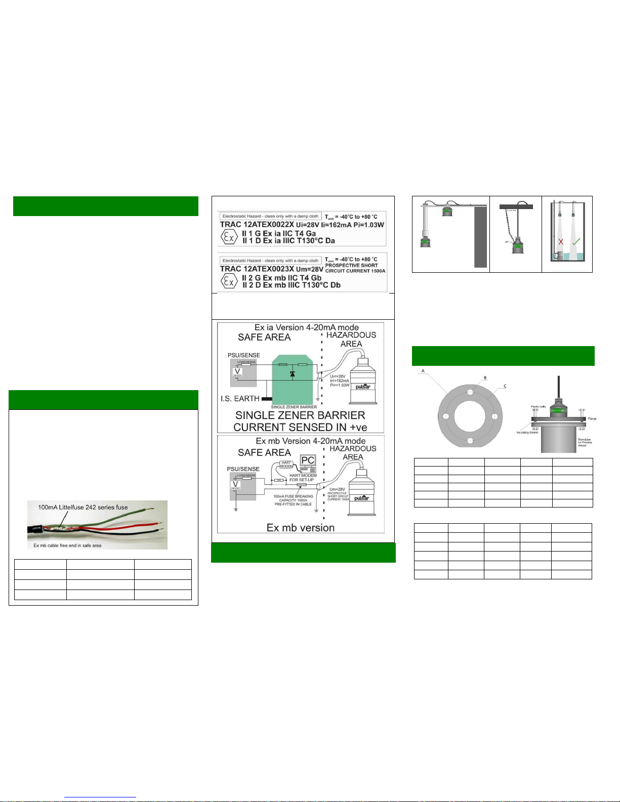
Hazardous Area Installation
All dBi transducers are ATEX certified for use in hazardous areas.
There are two different versions:
One certified to II 1 G Ex ia IIC T4 Ga & II 1 D Ex ia IIIC T130ºC Da
(Trac 12ATEX0022X) for use in zone 0, 1 & 2 applications (safety
barrier required), and another certified to II 2 G Ex mb IIC T4 Gb & II
2 D Ex mb IIIC T130ºC Db (Trac 12ATEX0023X) suitable for use in
zones 1 & 2 ( no barriers required).
The ‘X’ in the certification No.’s indicates that certain special
conditions apply: see EC Declaration of conformity on the flip side of
this document.
Ex mb version – This version must be supplied from apparatus that
provides protection from prospective short circuit currents up to
1500A. This fuse is fitted in the safe area end of the cable.
Wiring Detail
Colour
Description
Limits
RED
DC Power +ve
28V DC max.
BLACK
DC 0V
GREEN
Cable Screen
GENERAL INSTALLATION
The dB transducer should be installed directly above the liquid or solid
level with the transducer axis perpendicular to the surface to be
measured.
The transducer can be installed using the 1” BSP thread on the top of
the transducer or with the supplied 1” BSP to M20 thread adapter.
See figure 1 for examples.
FIGURE 1 FIGURE 2 FIGURE 3
In some applications it may not be possible to install the transducer
using either a flange or the 1” BSP thread, in these circumstances it
may be possible to suspend the transducer from its cable. In these
installations it is recommended that the transducer be secured using
a small chain fitted to one of the chain holes on the top of the
transducer, see figure 2.
When installing the transducer avoid aiming the transducer directly at
fixed obstructions as they may mask the required return echo from
the liquid or solid level being monitored, see figure 3.
Flanged versions of the transducer should be installed using plastic bolts with an
insulating gasket between the transducer flange and the process vessel flange. The
bolts should not be fully tightened as this may cause acoustic resonance that results in
increased ring down. A typical flange application is shown in figure 2.
NOTE: All extension cables must use 2 or 3 core screened cables
not exceeding 100nF between conductor to screen and 40
ohms/conductor.
ATEX labelling for the two versions of protection Ex ia & Ex mb
See full manual for more detail
 Loading...