


FLD50
THERMAL IMAGING SCOPE -
FRONT ATTACHMENT
CORE
FXD50
2-15
16-29
30-43
44-57
58-71
72-86
v.1115
Attention!
Export of model 76456 with a refresh rate of 50 Hz may
have export limitations depending on the laws in your
region.
Attention!
L'exportation du modèle 76456 avec un taux de
rafraîchissement de 50 Hz peut avoir des restrictions à
l'exportation, selon la législation de votre région.
Achtung!
Export vom Modell 76456 mit 50 Hz Bildwechselfrequenz
kann Exportbeschränkungen je nach dem Gesetz in Ihrer
Region unterliegen.
¡Atención!
La exportación del modelo 76456 con una frecuencia de
50 Hz puede tener restricciones de exportación según la ley
en su región.
Attenzione!
L'esportazione del modello 76456 con frequenza di 50 Hz
può avere limitazioni a seconda delle leggi del tuo paese.
Внимание!
Экспорт модели 76456 с частотой 50 Гц
может иметь экспортные ограничения в зависимости
от законодательства Вашего региона.
CAMÉRA - ATTACHMENT
THERMIQUE CORE
WÄRMEBILDGERAT VORDERANSATZ CORE
VISOR TÉRMICO VISOR ACOPLABLE CORE
TERMOCAMERA - VISORE
APPLICABILE ANTERIORMENTE CORE
ТЕПЛОВИЗИОННЫЙ МОНОКУЛЯР -
НАСАДКА CORE
THERMAL IMAGING SCOPE FRONT ATTACHMENT CORE

SPECIFICATIONS:
2
3
3
DESCRIPTION
CORE is a multifunctional thermal imaging device that can be operated
either as a monocular or a front attachment. The CORE unit as an
attachment is designed for the use in the nighttime and in the daylight in
inclement weather conditions (fog, smog, rain) to see through obstacles
hindering detection of targets (branches, tallgrass, thick bushes etc.).
CORE as a monocular allows the user to observe an object at a distance of
above 1000 metres. Unlike the image intensifier tube based night vision
devices, thermal imagers CORE do not require an external source of light
and are not affected by bright light exposure. The CORE unit has a wide
range application including night hunting, observation and terrain
orientation, search and rescue operations.
FEATURES
Quick “monocular-attachment” conversion (2 in 1 unit)
Quick mounting and removal of attachment
Detection range above 1 km
High contrast green monochrome display
Increased Recognition and Detection Software (IRIS technology)
(software based on intellectual dynamic equalization algorhythm)
Monocular’s digital zoom 2x
Three calibration modes - manual, automatic, semiautomatic
Three operating modes – “Rocks”, “Forest”, “Recognition”
Wireless remote control
Sustainable operation at temperatures from -25 °C to +50 °C
Degree of protection IPX7 (fully waterproof)
Compact size
Low weight
2
Microbolometer characteristics:
Detector type
Refresh rate, Hz
Pixel size, µm
Resolution, pixels
Type
Display:
Magnification, x
- monocular
- attachment
Digital zoom, x
Monocular’s eye relief, mm
Monocular’s exit pupil, mm
Diopter adjustment, D
Max. observation range of an animal
1.7 m long, m
Operational characteristics:
Degree of protection, IP
code (IEC60529)
Operating temperature, °C / °F
Weight (without/with batteries), kg//oz
Horizontal Field of view, m @100m
Model
Power supply
Battery type
Optical characteristics:
-25 … +50 / -13 ... +122
Uncooled
2
384x288
+5/-5
1200/1312
76456
Core FXD50
2.8
1
5 - 7.2 V
2
384x288
16
9
+5/-5
1200/1312
IPX7
76454
Core FLD50
5
5 - 7.2 V
0.4 / 0.48 // 14.1 / 17
19.5
OLED (Green Sapphire)
Uncooled
25
F50/1.2
2xCR123A
2xCR123A
Lens
PACKAGE CONTENTS
For improvement purposes, design of this product is subject to change.
Monocular CORE
Attachment’s eyepiece
Carrying case
Hand strap
Wireless remote control
User manual
Cleaning cloth
Warranty card
1
25
50
2.8
1
F50/1.2
16
5
19.5
Close-up range, m
3
3
IPX7
Resolution, pixel
640x480640x480
Dimensions, mm / inch
190x65x60 / 7.5x2.6x2.4
Max. operating time on a battery set, h
4 4
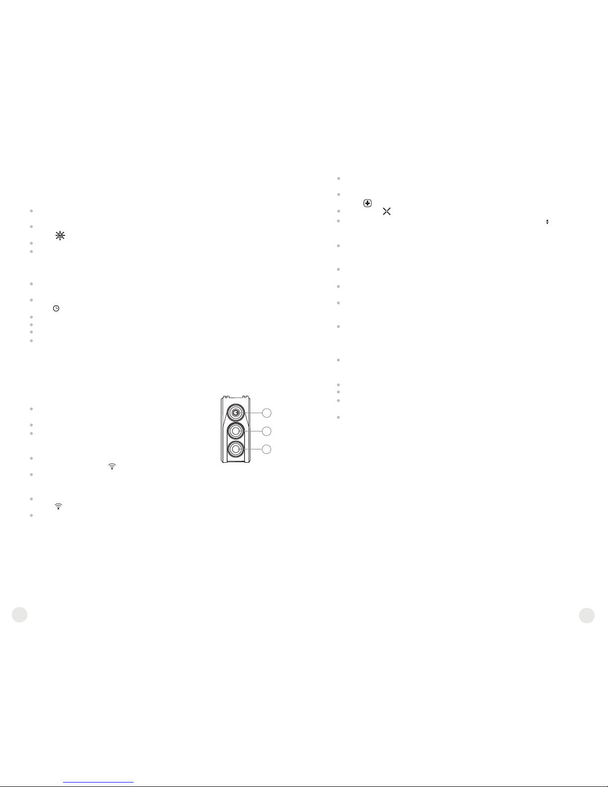
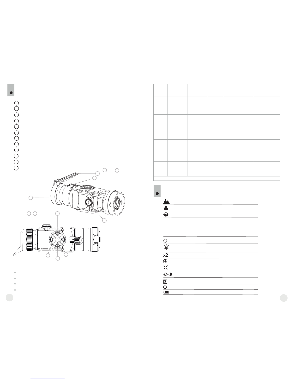
COMPONENTS AND CONTROLS
4
5
6
7
8
9
10
11
12
1
2
3
4
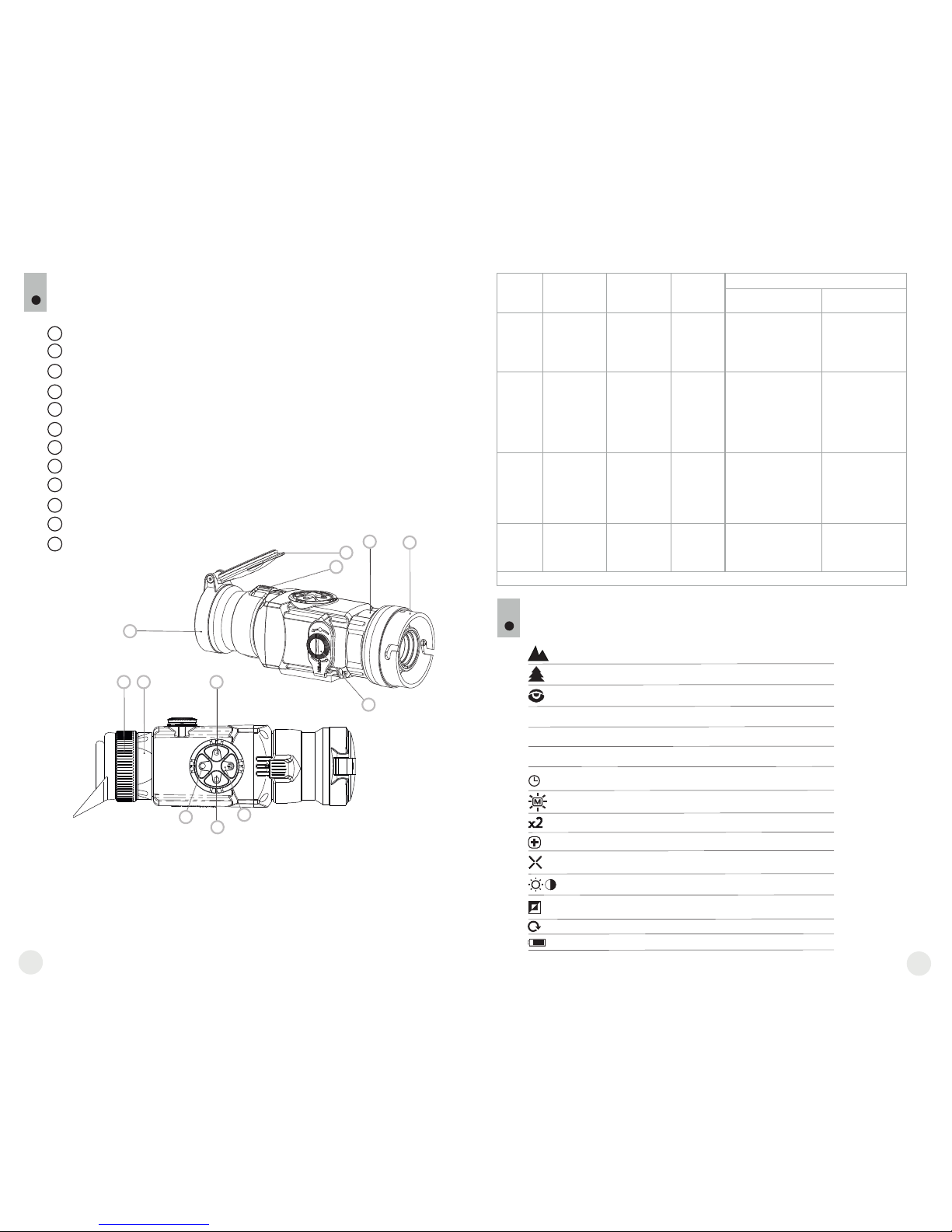
Lens cap
Objective lens
Lens focus knob
Eyepiece diopter adjustment ring
Eyepiece locking ring
Battery compartment cover
Bayonet-type ring of attachment’s eyepiece
Attachment’s eyepiece
“ON/OFF” button
“LEFT” navigation button
“RIGHT” navigation button
“MODE” button
Button “ON/OFF” (9)
Button “LEFT” (10)
Button “RIGHT” (11)
Button “MODE” (12)
Controls:
4
5
1
2
3
6
7
8
9
10
12
11
First short
press
Next short
press
Long press
Menu operation
Short press
Long press
Powering
the unit on
Unit calibration
Powering
the unit off
Unit calibration,
confirmation of
defective pixel
elimination –
in corresponding
menu option
Powering
the unit off
Increasing
brightness
and contrast
level*
x2 digital
zoom
(only for
monocular)
Menu navigation –
upwards and
rightwards
Increasing
brightness
and contrast
level*
Decreasing
brightness
and contrast
level
Color
inversion
Menu navigation –
downards and leftwards
Activating
contrast
control
mode
Activating
brightness
control
mode
Confirmation and
menu option exit
Entering
the menu
Confirmation and
menu option exit**,
main and auxiliary
menu exit.
**in some menu options (clock setup).
“ON/OFF”
“RIGHT”
“LEFT”
“MODE”
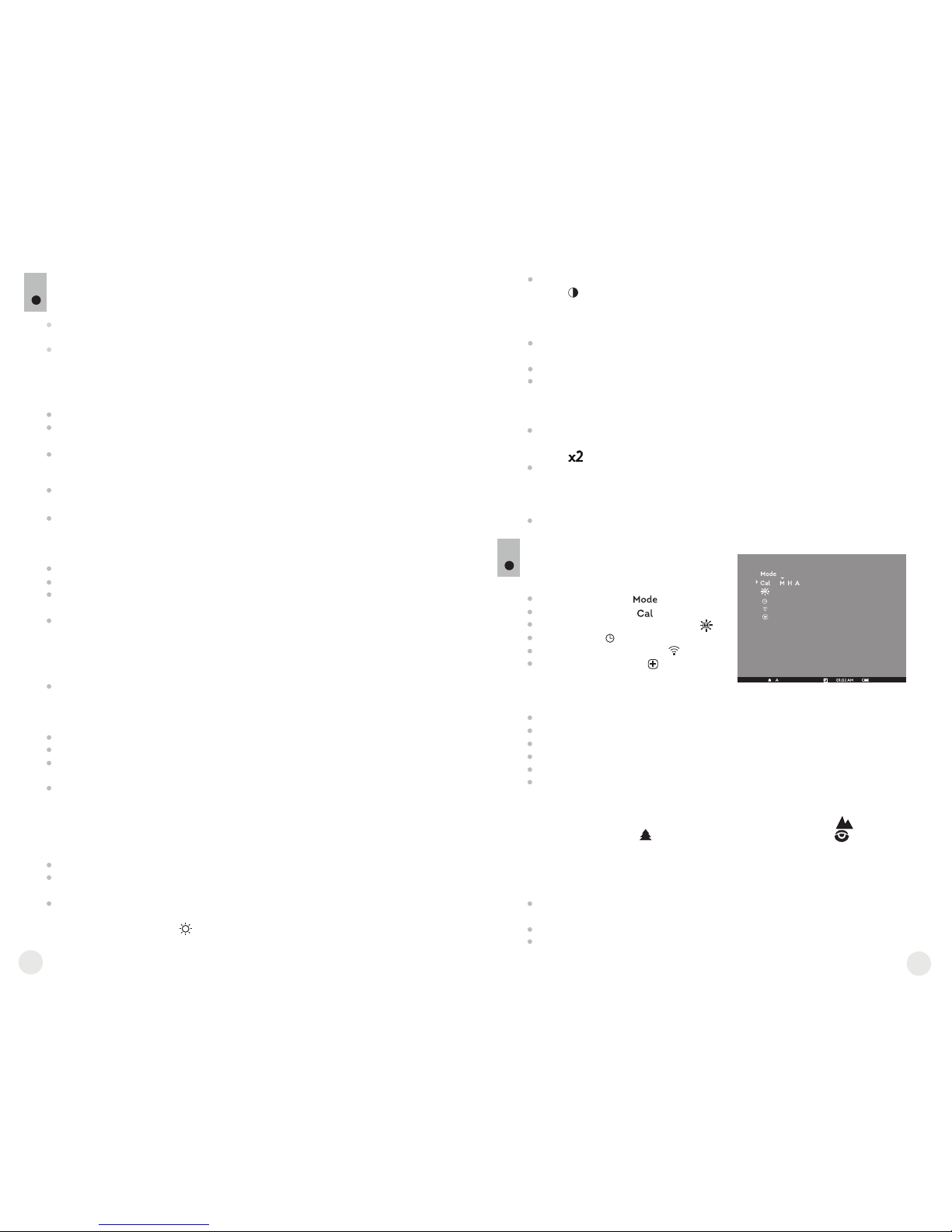
H
A
Semiautomatic calibration mode
Automatic calibration mode
Low battery indicator
Clock setup
2x digital zoom
Defective pixel repair option
Brightness and contrast setup
Image inversion modes: “White hot”/“Black hot”
Cross for defective pixel repair
Return to default defective pixel pattern
Brightness setting of menu icons
5
MENU / STATUS BAR ICONS:
M
Operating mode “Identification”
Manual calibration mode
Operating mode “Rocks”
Operating mode “Forest”
Decreasing
brightness
and contrast
level
* depending on the mode selected with MODE.
4
5
8.1. CORE as monocular.
Detailed description of the monocular CORE can be found in section
9 “OPERATION. CALIBRATION”.
OPERATION
8
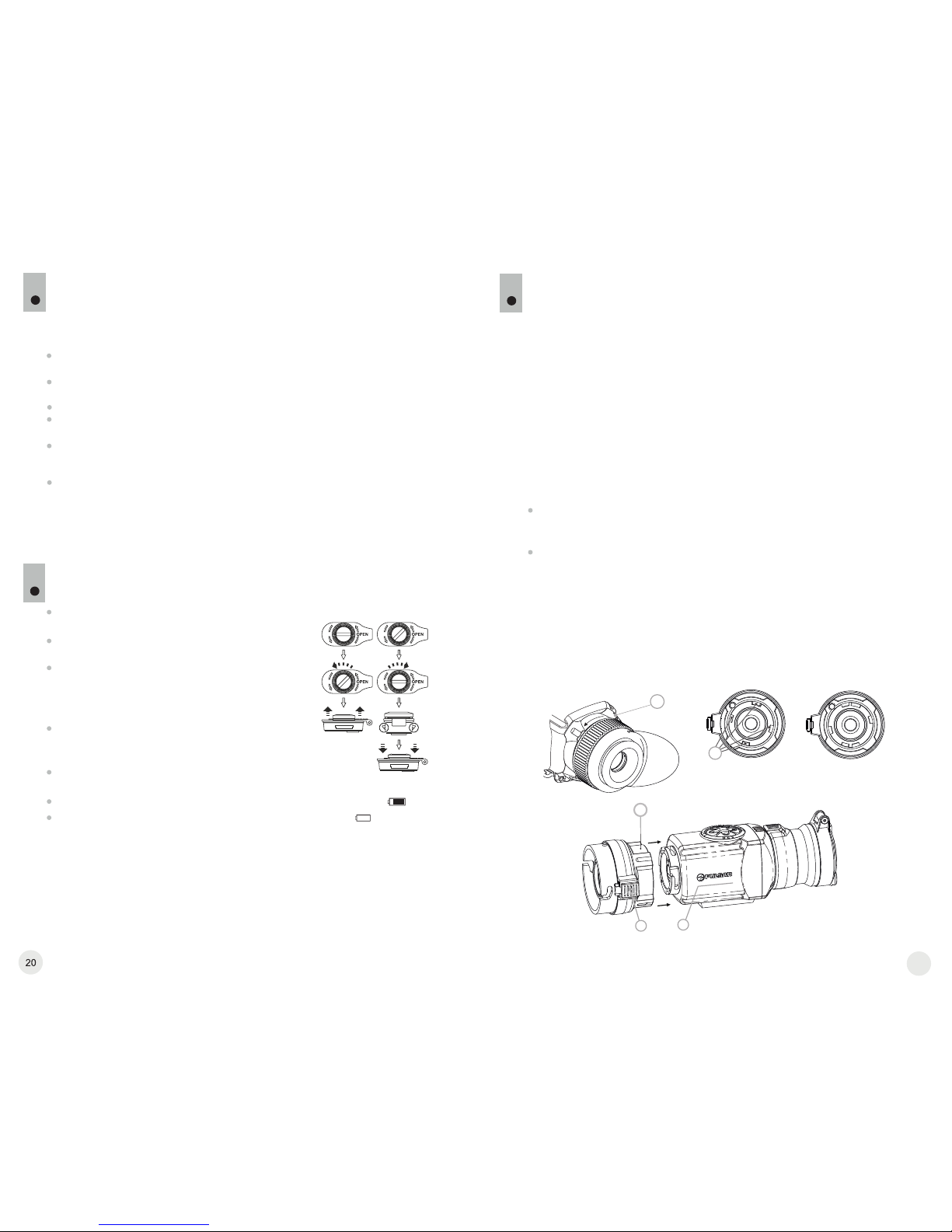
BATTERY INSTALLATION
7
Turn the battery com partmen t kn ob (6)
counterclockwise until stop and remove it.
Install two CR123A batteries according to the
marking on the battery compartment cover and
inside it.
Turn the battery compartment knob clockwise
until stop – the latches from both sides of the
cover will pull out (see the drawing).
Replace the battery cover and press it until its
clicking position - make sure the cover is
closed on both sides.
Battery charge level is displayed on the status
bar ( ).
In case of complete battery discharge, icon is
flashing on the status bar.
Unit CORE can be used as a monocular or front attachment for day device.
Original design allows the monocular to be quickly converted into attachment
and vice versa.
Note: please do not use batteries of different types or batteries with
various charge levels.
8.2. CORE as front attachment.
CORE as attachment is designed to use a day device both in the
nighttime and daytime in inclement weather (fog, smog, rain etc.).
To convert the monocular into attachment and to mount it on a day device,
please follow instructions as follows:
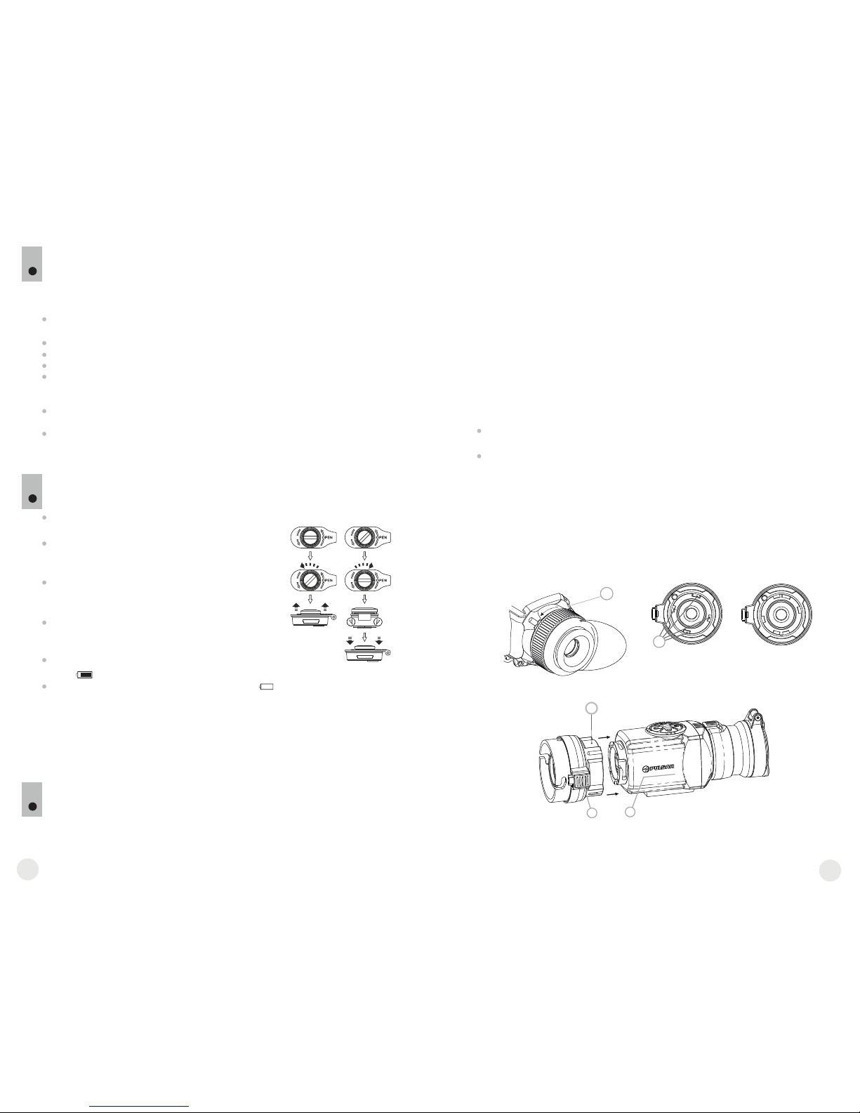
Stage 1. Mounting attachment’s eyepiece on CORE unit.
Rotate the eyepiece locking ring (5) counterclockwise until you hear a
click and remove the eyepiece (Fig. 1).
Mount the on the unit as follows:attachment’s eyepiece
- Make sure that the salients (A) of the are attachment’s eyepiece
located above the lower salients (see Fig.2).
- Locate the so that the lock (B) is parallel to the attachment’s eyepiece
Pulsar logo (L) on unit’s body (Fig.3).
- Insert the into unit’s body until stop and secure attachment’s eyepiece
it by turning the b (7) clockwise.ayonet-type ring
Before use make sure that you have mounted and adjusted the unit according
to the instructions of the section 8 “Operation”.
Store with the lens cap on in the carrying case.
Switch off the unit after use.
Attempts to disassemble or repair the unit will void the warranty!
The unit is designed for use in various operating temperatures. However, if it
has been brought indoors from cold temperatures, do not turn it on for 2 to 3
hours. This will prevent external optical surfaces from condensation.
To ensure reliable performance, it is recommended to carry out regular
technical inspections of the unit.
WARNING! Do not point the objective lens of the unit at intense sources
of light such as the sun. This may disable electronic components of the
unit. The warranty does not cover damage caused by improper
operation.
GUIDELINES FOR OPERATION
6
The unit has been designed for long-term use. To ensure sustainable
performance, please adhere to the following:
Fig.1
Fig.2
Fig.3
correct
wrong
Open:
Close:
5
6
7
А
L
B
7
Warning: do not use rechargeable batteries since their use causes
inaccurate battery level indication and and possible disconnection during
operation.
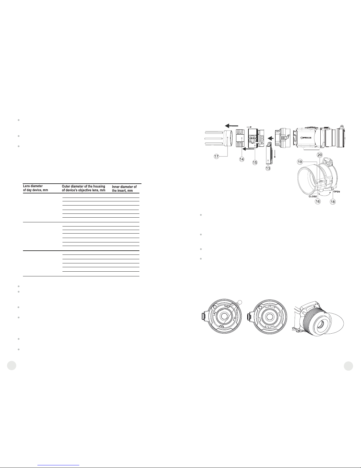
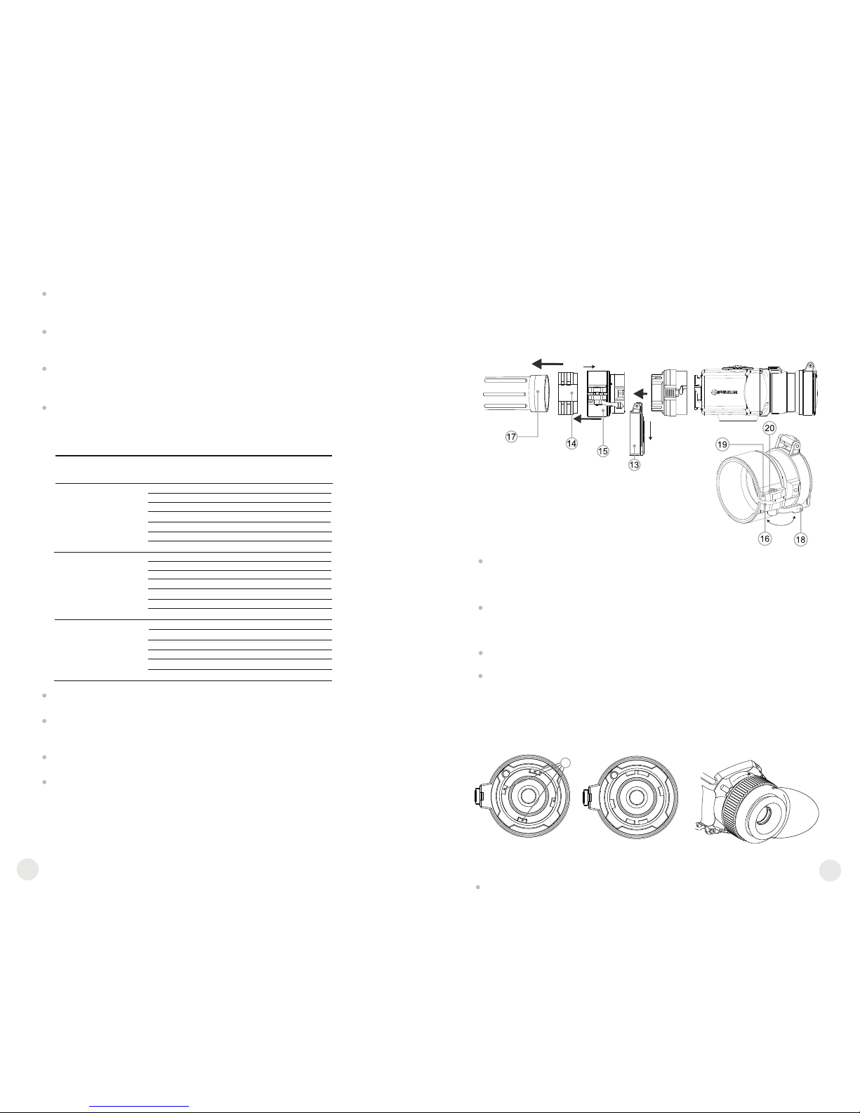
Stage 3. Mounting CORE unit on a day device
Insert firmly the CORE unit with mounted attachment’s eyepiece into the
cover adapter so that the pins in adapter’s body enter grooves of the
attachment’s eyepiece. Turn the CORE unit counterclockwise to hear a
click.
Tighten the screw (20) with the hex-nut wrench, to ensure that when turning
the lever, the adapter with insert tightly fits the objective lens of day device.
Mounting eyepiece on CORE unit
To mount the eyepiece on the unit, make sure that the lower salients (C) of
the eyepiece match the lower yellow salients (Fig. 5).
Insert the eyepiece into the unit’s body and turn the locking ring (5)
clockwise.
Stage 2. Installing the cover adapter on day device (using metal
Cover-adapters DN42/50/56 mm” (SKU#79124/79125/79126)
Select a cover adapter with an insert (bought separately) of the required
diameter depending on the outer diameter of the objective lens of the day
device.
The figures 42 mm, 50 mm, 56 mm in adapter's model name correspond
to the optical diameter of the lens of your day device.
Measure the outer diameter of the housing of the lens of your day device
and select an insert based on the data in the table below.
Example. If the lens diameter of your day device is 42mm, and the
measured outer diameter of the housing of the lens of your day device is
47.2 mm, you need to use an insert with marking “Ø 47”.
Compatibility chart of inserts for day devices
Remove the cover (13) from the Cover by turning it counterclockwise.
Install the insert (14) into the adapter (15) all the way in (Fig.4)
Important! The insert must be installed with the narrowed part
facing downward.
Install firmly the adapter with the insert onto the objective lens (17) of an
day device (Fig.4).
Snap the lever (18) from the original OPEN position to the CLOSE
position (Fig.4). Check that the adapter firmly fits the objective lens.
If you see there is a clearance, please:
- Loosen the locking screw (19) with the hex-nut wrench (S=2mm).
8
9
Fig.4
42
50
56
59.7-60.6
60.7-61.6
61.7-62.6
60
61
62
62.7-63.6
63
64
63.7-64.6
65
64.7-65.6
46.7-47.6
47.7-48.6
48.7-49.6
47
48
49
49.7-50.6
50
54.7-55.6
55.7-56.6
56.7-57.6
55
56
57
57.7-58.6
58
59
58.7-59.6
45.5
45.5
46
46
46.5
46.5
51.6
51.6
53.4
53.4
Pic.5
correct
wrong
Tighten the screw (20) with hex-nut wrench (S=4mm) with a clamping
force necessary to ensure that the adapter fits tightly the objective lens.
Tighten the locking screw (19).
С
Having turned the unit on, please make sure that the line of
horizon of you day device is parallel to the upper and lower edges
of the display of the CORE monocular.
It is recommended that you degrease the objective lens of your day
device and the inner side of the insert before installing the cover adapter.
To switch to contrast control, press briefly the “MODE” (12) button
(icon appears). Press briefly navigation buttons - “LEFT” (10) (decrease)
and “RIGHT” (11) (increase) to select contrast level (from 0 to 20).
Corresponding contrast level appears next to icon in the top right corner of
the display.
Point the unit at a warm object located at a certain distance, 100 meters, for
example.
Rotate the lens focus knob (3) until you achieve quality image.
After this adjustment no further dioptre adjustment should be required,
regardless of distance or other factors. Adjust image quality only with the
lens focus knob.
In automatic calibration mode the thermal imager calibrates by itself according
to the software algorythm. The detector (microbolometer) is closed with the
shutter automatically. User assisted calibration with the “ON/OFF” button is
allowed in this mode.
Power on the unit, open the lens cap.
Hold down the “MODE” button for two seconds to enter the menu.
Use the navigation buttons “LEFT” (10) and “RIGHT” (11) to select item Cal.
Select mode A. Press MODE to confirm.
At the moment of the automatic calibration the image will freeze for 1-2
seconds and you will hear the sound of the internal shutter.
Note: time intervals between calibrations depend on the heat of the detector.
The unit may require calibration more frequently on activation.
Focusing and adjusting the image
Open the lens cap (1).
Adjust sharp image of icons on the status bar by turning the eyepiece diopter
adjustment ring (4).
To control display brightness, press briefly navigation buttons - “LEFT” (10)
(decrease) and “RIGHT” (11) (increase). Selected brightness level (from 0 to
20) appears next to icon in the top right corner of the display.
OPERATION. CALIBRATION.
9
Open the lens cap (1).
Press briefly the “ON/OFF” (9) button to power on the unit, hold down the
“MODE” (12) button for two seconds to enter the menu.
Use the navigation buttons “LEFT” (10) and “RIGHT” (11) to select item Cal.
Select mode M. Press “MODE” to confirm. To exit the menu, press and hold
“MODE” for two seconds or wait 10 seconds for automatic exit.
Close the lens cap. Press the “ON/OFF” button to calibrate. The image will
freeze for 1-2 seconds. Then open the lens cap. Calibration is completed.
If you see image flaws (such as frozen image, vertical stripes etc.) re-calibrate
the unit with the lens cap closed.
Power on the unit, open the lens cap.
Hold down the “MODE” (12) button for two seconds to enter the menu.
Use the navigation buttons “LEFT” (10) and “RIGHT” (11) to select item Cal.
Select mode H. Press “MODE” to confirm.
Press the “ON/OFF” (9) button to calibrate. The image will freeze for 1-2
seconds and you will hear the sound of the internal shutter. Calibration is
completed.
Manual (silent) calibration mode
Power on the unit with “ON/OFF” (9) button. In case of low battery icon will
start flashing on the status bar.
Do the image calibration. Calibration levels background temperature of the
microbolometer and eliminates image flaws.ee calibration modes are
available: manual (M), semiautomatic (H) and automatic (А).
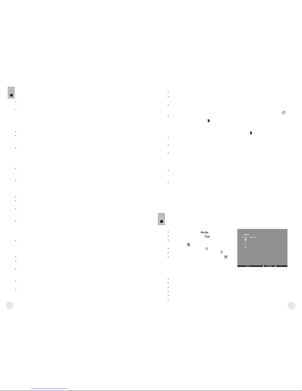
Operating mode
Calibration mode
Brightness setting of menu icons
Clock setup
Remote control activation
Defective pixel repair
MENU
10
The menu includes options as follows:
Status bar
The status bar shows information as follows:
Operating modes (“Rocks”, “Forest”, “Identification”)
Calibration mode (manual, semiautomatic, automatic)
Digital zoom x2 activated
Color inversion activated
Clock setup
Battery status
Operating modes
The unit features three automatic operating modes: “Rocks” (enhanced
contrast), “Forest” (low contrast) and “Identification” (improved
detail rendering).
Each mode includes optimal combination of parameters (brightness,
contrast, gain etc.) to deliver best possible image in specific viewing
conditions.
Press and hold down the “MODE” (12) button for two seconds to enter the
menu.
Press briefly “MODE” to confirm your choice.
Icon of the selected mode is shown on the status bar.
10
11
Semiautomatic calibration mode
Automatic calibration mode
Press and hold down the “RIGHT” (11) button for two seconds to activate
2x digital zoom (available only if the unit is used as a monocular).
Icon appears on the status bar.
Press and hold down the “LEFT” (10) button for two seconds to activate
colour inversion (functions “Hot white” and “Hot black”). When function
“White hot” is used, warm objects are represented in shades of bright
colour; “Black hot” represents objects in shades of dark colour.
Press and hold down “ON/OFF” (9) for two seconds to switch off the unit.
Other functions
Calibration modes
Please see section 8 “Operation” for details.
Press and hold down the “MODE” (12) button for two seconds to enter the
menu.
Press briefly navigation buttons - “LEFT” (10) and “RIGHT” (11) to select
icon
Select brightness level (1 to 10) with navigation buttons.
To exit the main menu, hold down the “MODE” button for two seconds or wait
10 seconds to exit automatically.
Press and hold down the “MODE” (12) button for two seconds to enter the
menu.
Press briefly navigation buttons - “LEFT” (10) and “RIGHT” (11) to select
icon . Press “MODE”.
Select time format “24” or “AM/PM” with navigation buttons.
Press “MODE” to proceed to hour setup. Set with navigation buttons.
Press “MODE” again to proceed to minute setup. Set with navigation buttons.
To exit the main menu, hold down the “MODE” button for two seconds or wait
10 seconds to exit automatically.
Remote control activation
The wireless remote control duplicates activation of unit, color inversion and
image calibration.
It has three buttons:
When operating the thermal imager, there is a possibility of defective (dead)
pixels (bright or dark dots with constant brightness) appearing on the
detector which are visible on the image.
Thermal unit CORE allows you to repair defective pixels on the detector
(microbolometer) using a software-based method.
Press and hold down the “MODE” (12) button for two seconds to enter the
menu.
Press briefly navigation buttons - “LEFT” (10) and “RIGHT” (11) to select
icon , press “MODE”.
Select icon in the pop-up submenu and press “MODE”.
The remote control has three buttons:
Button “ON” (22) – turning on/off the unit
(on – brief press/off – long press (2 sec)).
Button (23) - color inversion
Button “CAL” (24) – image calibration
To start using the wireless remote control you will need
to activate it:
Turn on the scope and select menu option
“RC activation”(icon ).
Press “MODE” (12) button, message “WAIT” will appear and countdown
will start within which you need to press and hold for two seconds any RC
button.
If the activation is successful, message “Complete” will appear next to
icon . The RC is ready for use.
If the RC does not work, replace the battery. To do this, unscrew the screws
on the rear panel of the RC, remove the cover, pull out the old battery and
insert a new CR2032 battery.
24
23
22
If you wish to return to the default defective pixel pattern (i.e. restore all
defective pixels previously repaired), select icon in the pop-up submenu
and press the “MODE” button.
Options “Yes” and “No” appear on the right of the “MODE” button.
Use navigation buttons to select “Yes” and press the “MODE” button.
If you choose not to return to default pixel pattern, select “No” and press
“MODE” button.
To exit the main menu, press and hold down the “MODE” button for two
seconds or wait 10 seconds to exit automatically.
Attention! One or two pixels in the form of bright white or black 1-2
pixels dots are allowed on the display of thermal imager. These pixels
cannot be repaired and are not a defect.
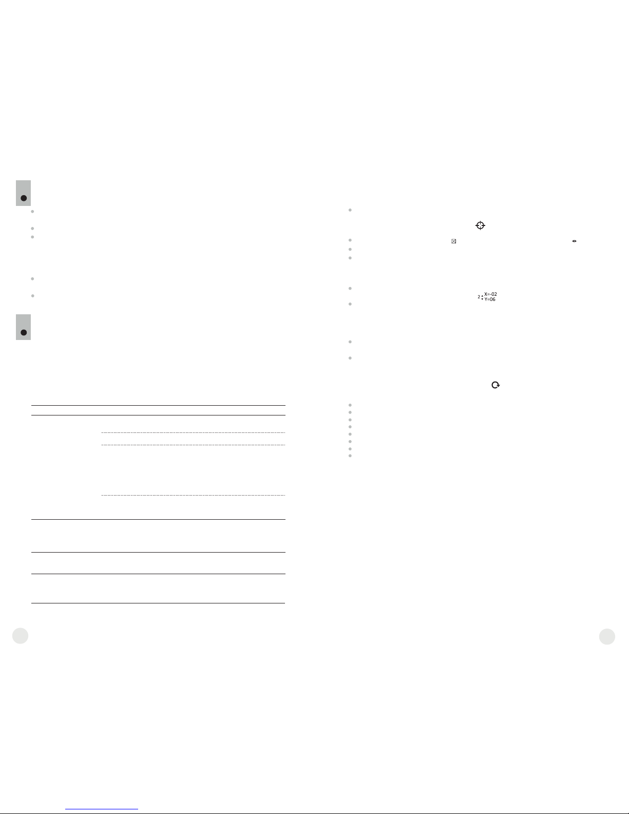
A red cross appears in the centre of display, coordinates (X; Y) of the
cross relative to the centre of display appear in the place of pop-up icons,
icons disappear.
Use navigation buttons to align the center of the cross with a defective
pixel (defective pixel should go out). Switch direction of the cross from
horizontal to vertical by a short press of the “MODE” button.
After the centre of the cross is aligned with a defective pixel, press the
“ON/OFF” (9) button to repair the pixel.
In case of success a short “OK” message appears next to the
coordinates.
Further on, move the cross to repair another defective pixel. When moving
the cross to the coordinates area, the latter goes to the lower right portion
of the display.
To exit menu option “Defective pixel repair”, press and hold button
“MODE” for two seconds.
Return to default defective pixel pattern
X=50
Y=50
12
13
Brightness setting of menu icons
Clock setup
Defective pixel repair
MAINTENANCE AND STORAGE
11
The unit features degree of protection IPX7 (fully waterproof, submersible at
1 meter for 30 minutes).
Attempts to disassemble or repair the scope will void the warranty!
Clean the scope's optical surfaces only if necessary, and use caution. First,
remove (by blowing with a blower brush or canned air) any dust or sand
particles. Then proceed to clean by using camera/lens cleaning equipment
approved for use with multicoated lenses. Do not pour the solution directly
onto the lens!
Always store the unit in its carrying case in a dry, well-ventilated space. For
prolonged storage, remove the batteries.
Batteries shall not be exposed to excessive heat such as sunshine, fire or the
like.
12
TROUBLESHOOTING
Listed below are some potential problems that may occur when using the
scope. Carry out the recommended checks and troubleshooting steps in the
order listed. Please note that the table does not list all of the possible
problems. If the problem experienced with the scope is not listed, or if the
suggested action meant to correct it does not resolve the problem, please
contact the manufacturer.
Problem
Possible cause Corrective action
The unit will not turn on.
.
The image is blurry, with
vertical stripes and uneven
background.
Batteries have been
incorrectly installed.
Oxidized contact points in the
battery compartment or
on the battery cover due to
“leaky” batteries or contact
points becoming exposed
to a chemically reactive solution.
The batteries are fully
exhausted or one or
several batteries are faulty.
Calibration is to be done.
Reinstall the batteries
observing polarity.
Clean the contacts of the battery
compartment or the battery cover.
Install fresh batteries.
Do the calibration according
to section 9 “OPERATION”
The image is too dark.
The lowest brightness level
is set.
Adjust display brightness.
14
15
Point of impact does not
match the aiming point.
Display calibration needs to be
done.
Do display calibration as per
guidelines below.
Display calibration
Press simultaneously and hold for two seconds buttons “LEFT” (10) and ”MODE”
(12) or RC buttons (23) and (24) to enter the auxiliary menu. Press buttons “LEFT”
(10) or “RIGHT”(11) to select menu item “Display calibration”. Press “MODE”
to confirm.
Auxiliary cross in a limiting frame and symbols will appear on the display .
First, match the auxiliary cross and the centre of sight’s reticle.
To move the frame with the cross horizontally and vertically, press buttons “LEFT” or
“RIGHT” (or RC buttons (22),(24)). Movement takes places upon both short and long
press. To switch movement direction from horizontal to vertical, press button “MODE”
or (23) RC button.
Second, hold “MODE” (or (23) RC button) for two seconds. Figure “2” and X, Y
coordinates values appear next to the icon .
While holding the reticle in the aiming point, move the auxiliary cross to the point of
impact with buttons “LEFT” or “RIGHT” (or RC buttons (22),(24). To switch movement
direction from horizontal to vertical, press button “MODE” or (23) RC button.
Horizontal/vertical travel range of the auxiliary cross relative to the limiting frame is +/-
10.
Eventually the auxiliary cross should match the point of impact, with the sight's reticle
being held in the aiming point.
To save display calibration parameters, keep the “MODE” button (or (23) RC button)
pressed for two seconds - display will show “OK” message; the image of the target
centre should now coincide with the centre of the of sight's reticle.
To restore factory settings, select “Yes” in the item “Default settings”.
Parameters as follows are restored to factory settings:
Operating mode – “Forest”;
Image calibration mode – automatic;
Brightness of menu symbols – 5;
Display calibration – coordinates X=0, Y=0;
Magnification – x1;
Color inversion - off;
Brightness settings – 10;
Contrast settings – 6.
Note. Auxiliary menu items (“Display calibration” and “Default settings”) are only
available when the unit is in attachment mode.
1
Battery cover is not tightly closed. Close tightly the battery cover.
12
17
16
3
DESCRIPTION
Le CORE est un appareil à imagerie thermique multifonction qui peut être
utilisé soit en monoculaire soit en attache frontale. Le CORE en tant
qu’attache est destiné à être utilisé sur appareils de jour, à la fois de jour
comme de nuit et par mauvais temps (brouillard, mauvaise visibilité, pluie)
pour voir au travers des obstacles rendant la détection de cibles difficile
(branches, herbes hautes, buissons épais etc.).
Le CORE en tant que monoculaire permet à l’utilisateur de observer un
objet à une distance plus de 1000 mètres. A la différence des dispositifs de
vision nocturne conçus à partir d’un tube avec intensificateur d’image, les
caméras thermiques CORE ne nécessitent pas de source de lumière
externe et ne craignent pas l'exposition à la lumière vive. La caméra
thermique CORE peut être utilisée dans un large champ d’utilisation, pour
la chasse nocturne, l'observation et l'orientation, ainsi que pour les
opérations de recherche et de sauvetage.
CARACTERISTIQUES SPECIFIQUES
Conversion "monoculaire-attache" rapide (2 en 1)
Montage et démontage rapide de l'attache
Portée de détection plus de 1 km
Affichage en monochrome vert à haut niveau de contraste
Amélioration de la reconnaissance et de la détection par le logiciel
(technologie IRIS) (basé sur un logiciel avec un algorithme
inteligent d'égalisation dynamique)
Zoom numérique 2x du monoculaire
Trois modes d'étalonnage - manuel, automatique, semiautomatique
Trois modes d'observation - "Montagne/Rocheux", "Forêt",
"Reconnaissance"
Télécommande sans fil
Fonctionnement stable à des températures de -25 °C à +50 °C
Degrés de protection IPX7 (entièrement étanche à l'eau)
Taille compacte
Faible poids
2
Microbolomètre:
Type
Taux de rafraîchissement, Hz
Taille de pixel, µm
Resolution, pixels
Type
L'écran:
Grossissement optique, x
- monoculaire
- attache
Zoom numérique, x
Dégagement oculaire du
monoculaire, mm
Diamètre de la pupille de sortie du
monoculaire, mm
Ajustement dioptrique, D
Distance max. d’observation
d’un animal 1,7m de longueur, m
Caractéristiques fonctionnelles:
Classe de protection, code IP
(IEC 60529)
Température d'utilisation, °C
Poids (sans/avec piles), kg
Champ vision horizontal, m@100m
Modèle
Alimentation du dispositif
Caractéristiques optiques:
-25 … +50
non-refroidi
2
384x288
+5/-5
1200
76456
Core FXD50
2,8
1
2
384x288
16
9
+5/-5
1200
IPX7
76454
Core FLD50
5
0,4 / 0,48
19,5
OLED (Green Sapphire)
non-refroidi
25
F50/1.2
Objectif
CONTENU DE L'EMBALLAGE
Le design de ce produit pourrait-être amené à changer, afin d'améliorer son utilisation.
Monoculaire CORE
Oculaire de l’attache
Housse
Dragonne
Télécommande sans fil
Chiffonette
Guide de l'utilisateur
Carte de garantie
1
25
50
2,8
1
F50/1.2
16
5
19,5
Distance de mise-au-point
minimale, m
3
3
IPX7
-25 … +50
0,4 / 0,48
640x480 640x480
La résolution, pixel
5 - 7,2 V
5 - 7,2 V
2xCR123A
2xCR123A
190x65x60 190x65x60
Dimensions, mm
4 4
Type de piles
Temps de fonctionnement continu
avec ensemble de piles, h
COMPOSANTS ET COMMANDES
4
5
6
7
8
9
10
11
12
1
2
3
4
Protège-objectif
Objectif
Molette de focalisation de l'objectif
Bague du réglage dioptrique de l'oculaire
Anneau de verrouillage de l’oculaire
Couvercle du compartiment à piles
B de type bayonette ague de verrouillage
L’oculaire d’attache
Bouton “ON/OFF”
Bouton de navigation “GAUCHE”
Bouton de navigation “DROIT”
Bouton “MODE”
Bouton “ON/OFF” (9)
Bouton “GAUCHE” (10)
Bouton “DROIT” (11)
Bouton “MODE” (12)
COMMANDES :
4
5
1
2
3
6
7
8
9
10
12
11
Pression rapide
premiere
Pression rapide
suivante
Pression
longue
Opération du menu
Pression rapide
Pression longue
Mise en fonction
de l’appareil.
Calibration
de l’appareil.
Mise hors
fonction
de l’appareil.
Calibration de l’appareil,
confirmation d’élimination
des pixels défectueux –
dans une option du menu
correspondant.
Mise hors fonction
de l’appareil.
Augmentation
du niveau de
luminosité et
de contraste*
Zoom
numérique
2x
(seulement
pour
monoculaire).
Menu navigation vers le haut et
vers la droite.
Augmentation
du niveau de
luminosité et
de contraste*
Réduction du
niveau de
luminosité
et de contraste*
Mode
“Inversion
Couleur”
Navigation dans le
menu - vers
le bas et vers
la gauche
Activation
du mode
de réglage
du contraste
Activation
du mode
de réglage
de la luminosité
Confirmer et quitter
une option du menu
Entrer dans
le menu
Confirmer et quitter
une option du menu**,
quitter le menu
principal et
supplémentaire.
**dans certains options du menu (réglage de l’horloge).
“ON/OFF”
“DROIT”
“GAUCHE”
“MODE”
H
A
Mode d’étalonnage Semi-automatique
Mode d’étalonnage Automatique
Affichage de charge de batteries
Régime d'ajustage de l'heure
Zoom numérique 2x
Mode d'élimination des pixels défectueux
Réglage du niveau de luminosité et de contraste
Régimes “White hot / Black hot”
Croix pour éliminer des pixels défectueux
Retour à la carte d'usine des pixels
Réglage du niveau de luminosité
des icônes de menu
5
PICTOGRAMMES DU MENU / BARRE D’ETAT
M
Mode d'opération “Reconnaissance”
Mode d’étalonnage Manuel
Mode d'opération “Montagne/Rocheux”
Mode d'opération “Forêt”
Réduction du
niveau de
luminosité
et de contraste*
12
19
18
* selon mode sélectionné avec MODE
8.1. CORE comme monoculaire.
Description détaillée du monoculaire CORE peut être trouvée dans la section 9
"OPERATION. CALIBRATION ".
UTILISATION
8
INSTALLATION DES PILES
7
Tournez le bouton du compartiment à piles (6)
dans le sens antihoraire en butée et le retirez.
Installez deux piles CR123A selon le marquage
sur le couvercle du compartiment à piles.
Remettez le couvercle et tournez le bouton du
compartiment à piles dans le sens horaire - les
loquetes de les deux côtes vont ressortir (voir
schéma).
En replaçant le couvercle effectue r une
pression dessus, jusqu’à un clic de position, le
couvercle se refermera.
Assurez-vous que le couvercle est fermé sur
deux côtes.
Le CORE peut être utilisé comme un monoculaire ou attache frontale pour la
vision de jour. La conception originale permet au monoculaire d'être
rapidement converti en attache et vice-versa.
Note: veuillez ne pas utiliser de piles de différents types ou des piles
avec des niveaux différents de charge.
8.2. CORE en attache frontale.
Le CORE en attache est conçu pour utiliser un appareil de jour à la fois de
nuit et de jour, en cas d'intempéries (brouillard, fumée, pluie, etc.).
Pour convertir le monoculaire en attache et pour le monter sur un appareil
de jour, veuillez suivre les instructions suivantes:
Étape 1. Montage de l’oculaire d’attache sur l’habitacle du CORE
Tournez la bague de verrouillage de l'oculaire (5) dans le sens
antihoraire jusqu'à ce que vous entendiez un clic et retirez l'oculaire
(Fig. 1).
Montez sur l'appareil comme suit:l’oculaire d’attache
- Assurez-vous que les reliefs (A) de soient situés l’oculaire d’attache
au-dessus des reliefs inférieurs (Fig.2).
- Localise de sorte que le verrou (B) soit parallèle z l’oculaire d’attache
au logo Pulsar (L) sur le corps de l’appareil (Fig.3).
- Insérez dans le corps de l’appareil jusqu'à la l’oculaire d’attache
butée et fixez-le en tournant la bague de verrouillage (7) de l’adaptateur
de type bayonette dans le sens horaire.
Avant utilisation, vérifiez que vous avez installé et fixé l’appareil selon les
instructions de la section 9 “ ”.Focalisation et réglage de l'image
Conservez l’appareil avec le protège objectif en place sur l'objectif,
lorsque dans l’étui.
N'oubliez pas d'arrêter l’appareil après utilisation!
Il est défendu de réparer et démonter l’appareil, qui rendra caduque
la garantie!
L’appareil est conçu pour des températures d’utilisation variées et
étendues. Néanmois si l'appareil est apporté du froid dans un local
chaud, ne le mettez pas en marche pendant 2-3 heures.
Afin de garantir une performance fiable, il est recommandé de réaliser
des inspections techniques de l’appareil de temps à autre.
ATTENTION! Ne pointez pas l'objectif de l'appareil vers des sources
de lumière intenses comme le soleil. Cela peut endommager les
composants électroniques de l'appareil. La garantie ne couvre pas
les dommages causés par une utilisation inappropriée.
PARTICULARITES D’EMPLOI
6
L’appareil est conçu pour une utilisation prolongée. Pour assurer une
performance durable, veuillez suivre les recommandations suivantes:
Fig.2
Correcte
Ouvrir:
Fermer:
5
Incorrecte
Fig.3
Fig.1
21
А
L
B
7
Si les piles sont complètement déchargées, une icône clignotante
apparaît sur la barre d'état.
Attention: ne pas utiliser des piles rechargeables, car pendant leur
utilisation la charge de la batterie pouvait être affiché incorrectement et une
déconnexion accidentelle pendant le fonctionnement est aussi possible.
Le niveau de chargement des piles s'affiche sur la barre d'état ( ).
Etape 3. Montage du CORE sur un appareil de jour
Insérez fermement le CORE avec installé dans l’oculaire d’attache
l'adaptateur du couvercle, de sorte que les broches dans le corps de
l'adaptateur pénètrent dans les rainures de . Tournez le l’oculaire d’attache
CORE dans le sens antihoraire jusqu’à entendre un clic.
Serrer la vis (20) av urer que lorsque vous ec une clé hexagonale, pour ass
tournez le levier, l'adaptateur avec insert s’adapte parfaitement à la lentille
de l'objectif de appareil de jour.
Pour monter l'oculaire sur l'appareil, assurez-vous que les reliefs inférieurs
(C) de l'oculaire correspondent aux reliefs jaunes inférieurs (Fig. 5).
Insérez l'oculaire dans le corps de l'appareil et tournez la bague de
verrouillage (5) dans le sens horaire.
Etape 2. Installation de l’adaptateur pour couvercle sur un appareil
de jour (en utilisant les adaptateurs pour couvercle en metal
DN42/50/56 mm” (SKU#79124/79125/79126)
Sélectionnez un adaptateur/clapet de protection avec un insert (acheté
séparément) du diamètre requis, selon le diamètre extérieur de l’objectif
de votre appareil de jour (voir tableau ci-dessous pour reference).
Les chiffres de 42 mm, 50 mm ou 56 mm qui figurent dans la designation
de l’adaptateur, correspondent au diamètre de l’objectif de l’appareil de
jour.
Mesurez le diamètre extérieur de l’habitacle de l’objectif de votre
appareil de jour et sélectionnez un insert, selon les données du tableau
ci-dessous.
Exemple: si le diamètre de l’objectif est égal à 42mm et le diamètre
extérieur mesuré de l’objectif est de 47,2mm, il convient d’utiliser un
insert portant la marquage de Ø 47.
Retirez le couvercle (13) de l’adaptateur en effectuant une rotation dans
le sens anti-horaire.
Installez l'insert (14) dans l'adaptateur (15) jusqu’au fond (Fig.4).
Important! Avant d’inserer l’insert, verifiez que sa partie plus étroite
soit en avant.
Installez fermement l'adaptateur avec l'insert sur la lentille de l'objectif
(18) d’un appareil de jour (fig.4).
Enclenchez le levier (19) de la position OUVERTE d'origine à la position
FERMEE (Fig. 4).
Attention! Avant la mise en place de , il est l’oculaire d’attache
recommandé de degraisser le corps de l’appareil de jour et le côté
interne de l'insert .
Correcte Incorrecte
12
23
22
- Desserrer la vis de verrouillage (19) avec la clé à embout hexagonale
(S=2 mm).
- Serrer la vis (20) avec une clé à embout hexagonale (S=4mm) avec
une force de serrage nécessaire pour assurer que l'adaptateur se
joigne bien à la lentille d'objectif.
- Serrer la vis de verrouillage (19).
Vérifier que l'adaptateur soit installé fermement sur l'objectif. Si vous
découvrez qu'il y a un jeu, veuillez:
Montage de l’oculaire sur le CORE
Fig.5
FERMEE
OUVERTE
Diamètre intérieur
de l'insert, mm
42
50
56
59,7-60,6
60,7-61,6
61,7-62,6
60
61
62
62,7-63,6
63
64
63,7-64,6
65
64,7-65,6
46,7-47,6
47,7-48,6
48,7-49,6
47
48
49
49,7-50,6
50
54,7-55,6
55,7-56,6
56,7-57,6
55
56
57
57,7-58,6
58
59
58,7-59,6
45,5
45,5
46
46
46,5
46,5
51,6
51,6
53,4
53,4
Tableau de compatibilité des inserts pour les appareils diurnes
Diamètre de la lentille de
l'appareil diurne, mm
Diamètre extérieur du
boîtier de l'objectif de
l'appareil, mm
С
Attention! Assurez-vous que la ligne d'horizon de votre appareil
de jour est parallèle aux bords supérieur et inférieur de l'écran du
monoculaire CORE.
Fig.4
En utilisant le mode automatique l’imageur thermique se calibre selon
l'algorithme du programme. Le detecteur (microbolomètre) se ferme
automatiquement par le rideau intérieur. Dans ce mode il est admissible de
calibrer le dispositif par l'utilisateur à l'aide du bouton “ON/OFF” (9).
Mettez l’appareil en fonction, ouvrez le couvercle de l'objectif.
Appuyez sur le bouton “MODE” et tenez le appuyé pendant deux secondes
pour accéder au menu.
Utilisez les boutons de navigation “GAUCHE” (10) et “DROITE” (11)
choisissez le terme Cal. Choisissez ensuite le mode A. Appuyez sur “MODE”
pour confirmer votre choix.
Lors de l’étalonnage automatique, l'image s'immobilisera pendant 1-2
secondes et vous étendrez le son de l’obturateur à l’intérieur.
Note: les intervalles de temps entre les étalonnages dépend de la chaleur du
detecteur. L’appareil peut avoir besoin d’un étalonnage plus fréquent, par
activation.
MISE EN SERVICE ET ÉTALONNAGE
9
Ouvrez le couvercle (1) de l'objectif.
Appuyez brièvement sur le bouton “ON/OFF” (9) pour allumer l’appareil,
appuyez sur le bouton “MODE” (12) et tenez-le appuyé pendant deux
secondes pour accéder au menu.
Utilisez les boutons de navigation “GAUCHE” (10) et “DROITE” (11)
choisissez le terme Cal. Choisissez ensuite le mode M. Appuyez sur “MODE”
pour confirmer votre choix. Pour quitter le menu appuyez sur le bouton
“MODE” et tenez-le appuyé ou attendez 10 secondes pour la sortie
automatique.
Fermez le couvercle de l'objectif. Pour l’étalonnage appuyez sur le bouton
“ON/OFF” (9). L'image s'immobilisera pendant 1-2 secondes. Ouvrez
ensuite le couvercle de l'objectif. L’étalonnage est donc effectué.
Dans le cas d'apparition d’artefacts (image figée, bandes verticales etc.)
refaites l’étalonnage une seconde fois, avec le couvercle de l'objectif fermé.
Mode d’étalonnage manuel (silencieux)
Mettez le dispositif en service en appuyant sur le bouton “ON/OFF” (9) en
cas de décharge des piles, une icône commence à clignoter.
Effectuez l’étalonnage de l'image. L’étalonnage permet d'égaliser la plage
de températures du microbolomètre et d'éliminer les défauts de l'image.
Il y a trois modes d’étalonnage: manuel (M), semi-automatique (H),
automatique (А).
Mode d'opération
Mode d’étalonnage
Réglage de luminosité des icones
au menu
Réglage de l’horloge
Activation de la télécommande
Élimination des pixels défectueux
MENU
10
Le menu principal comprend les points suivants:
Barre d’état
Dans la barre d’état s’affichent les informations suivantes:
Modes d'opération – “Rochers/Montagne”, “Forêt”, “Reconnaissance”
Mode d’étalonnage – manuel, automatique, semi-automatique
Zoom numérique 2x activé
Inversion des couleurs de l'image activée
Réglage de l’horloge
Niveau des piles
Mode d’étalonnage semi-automatique
Mettez l’appareil en fonction, ouvrez le couvercle de l'objectif.
Appuyez sur le bouton “MODE” (12) et tenez-le appuyé pendant deux
secondes pour accéder au menu.
Utilisez les boutons de navigation “GAUCHE” (10) et “DROITE” (11)
choisissez le terme Cal. Choisissez ensuite le mode H. Appuyez sur “MODE”
pour confirmer votre choix.
Pour effectuer l’étalonnage, appuyez sur le bouton “ON/OFF” (9). L'image
s'immobilisera pendant 1-2 secondes et vous étendrez le son de l’obturateur
à l’intérieur. L’étalonnage est donc effectué.
Mode d’étalonnage automatique
Focalisation et réglage de l'image
Ouvrez le protège objectif (1).
Ajustez la netteté des pictogrammes sur la barre d’état, en tournant la
bague de réglage dioptrique de l'oculaire (4).
Afin de régler la luminosité de l’écran, appuyez brièvement sur les boutons “GAUCHE” (10) (réduire) ou “DROITE” (11) (augmenter). Le niveau de
luminosité (de 0 à 20) s’affiche en haut à droite de l’écran près de l’icône .
Afin de régler le contraste de l’écran, appuyez brièvement sur le bouton
“MODE” (12) (l’icône s’affiche). Appuyez brièvement sur les boutons “GAUCHE” (10) (réduire) and “DROITE” (11) (augmenter) pour
sélectionner le niveau de contraste (de 0 à 20). Le niveau de contraste
s’affiche en haut à droite de l’écran près de l’icône .
Pointez l’appareil en direction d’un objet chaud situé à une certaine
distance, par exemple à 100 m.
Effectuez une rotation de la molette de focalisation de la lentille (3) jusqu'à
obtenir une qualité de qualité.
Après cet ajustement, plus aucun réglage du dioptre ne devrait être
nécessaire, peu importe la distance ou les autres facteurs. Réglez la qualité
de l’image seulement avec la molette de focalisation.
12
25
24
Pour éteindre le dispositif, appuyez sur le bouton “ON/OFF” (9) et tenez le
appuyé pendant deux secondes.
Appuyer sur le bouton “DROIT” (11) et tenez le appuyé pendant deux
secondes, afin de pouvoir activer le zoom numérique 2x (disponible
seulement si l’appareil est utilisé comme un monoculaire).
Pour activer l'inversion de couleur de l'image (fonctions «White hot» et
«Black hot»), appuyez sur le bouton “GAUCHE” (10) et maintenez le
appuyé pendant deux secondes. L'utilisation de la fonction «White hot»
(blanc chaud) permet d'afficher les objets chauds en couleurs plus claires;
«Black hot» (noire chaud) – les objets chauds s'affichent en nuances plus
foncées.
Autres fonctions

Modes d’étalonnage
Pour en savoir plus, veuillez consulter la section 8 “Utilisation”.
Appuyez sur le bouton “MODE” (12) et tenez-le appuyé pendant deux
secondes pour accéder au menu.
Appuyez brièvement sur les boutons de navigation - “GAUCHE” (10) et
“DROIT” (11) pour choisir l’ icône .
Ajustez le niveau de la luminosité (de 1 à 10) avec les boutons de navigation.
Pour quitter le menu appuyez sur le bouton “MODE” et tenez-le appuyé 2
secondes ou attendez 10 secondes pour sortir automatiquement.
Appuyez sur le bouton “MODE” (12) et tenez-le appuyé pendant deux
secondes pour accéder au menu.
Appuyez brièvement sur les boutons de navigation - “GAUCHE” (10) et
“DROIT” (11) pour choisir l’icône . Appuyez sur “MODE”.
Choisissez le format d’affichage de l’heure “24” ou “AM/PM” avec les
boutons de navigation.
Afin de passer au réglage de l’heure, appuyez sur “MODE”. Réglez à l’aide
des boutons de navigation.
Afin de passer au réglage des minutes, appuyez sur “MODE”. Réglez à l’aide
des boutons de navigation.
Pour quitter le menu appuyez sur le bouton “MODE” et tenez-le appuyé 2
secondes ou attendez 10 secondes pour sortir automatiquement.
Elimination des pixels défectueux
Pendant le fonctionnement de la caméra thermique, l’apparition de pixels
(points lumineux ou foncés) défectueux (“morts”) apparaissant sur le
détecteur est possible, ceux-ci sont visibles à l’image.
La caméra thermique CORE vous permet d'éliminer les pixels défectueux
sur le detecteur (microbolomètre) à l’aide d’un programme.
Elle comporte trois boutons:
Bouton “ON” (22) – marche/arrêt de l’appareil
(on – appuyez brièvement /off – appuyez longuement
(2 sec)).
Bouton (23) - inversion des couleurs.
Bouton “CAL” (24) – étalonnage.
Pour commencer à utiliser la télécommande à distance, son activation est
nécessaire:
Mettez l’appareil en service et choisissez l’option au menu “Activation de
la RC” (l’icône ).
Appuyez sur le bouton “MODE” (12), le message “Wait” apparaît, le
compte à rebours démarre, au cours duquel il faut appuyer sur n’importe
lequel des boutons de la télécommande et le maintenir appuyé pendant
deux secondes.
Si l’activation est réalisée avec succès, le message “Complete” apparaît à
côté de l’icône . La télécommande est prête pour utilisation.
En cas d’affichage du message “Error” (Erreur), recommancez la
procédure.
Si la télécommande ne fonctionne toujours pas, changez la pile. Pour cela
dévissez les vis à l’arrière du boitier, enlever le couvercle et sortez
l’ancienne pile et insérez une nouvelle CR2032.
Si vous souhaitez faire un retour au précédent pixel defectueux (c'est-àdire pour restaurer tous les pixels defectueux précédemment réparés),
choisissez le pictogramme dans le sous-menu et appuyez sur le bouton
“MODE”.
A droite du pictogramme apparaissent les options “Yes” ou “No”.
A l'aide des boutons de navigation choisissez “Yes” et appuyez le bouton
“MODE”.
Appuyez sur le bouton “MODE” (12) et tenez le appuyé pendant deux
secondes pour entrer dans le menu.
Appuyez brièvement sur les boutons de navigation - “GAUCHE” (10) et
“DROITE” (11) choisissez l’icône , appuyez sur “MODE”.
Choisissez le pictogramme dans le sous-menu et appuyez sur
“MODE”.
Une croix rouge apparait au centre de l’écran, coordonnez les (X;Y) de
la croix par rapport au centre de l'écran, à la place des icones, les icones
disparaissent de l'écran.
Utilisez les boutons de navigation pour aligner le centre de la croix avec le
pixel defectueux (le pixel defectueux devrait disparaitre). Changez de
direction la croix d’horizontal à vertical par une pression rapide du bouton
“MODE”.
Après que le centre de la croix soit aligné avec le pixel défectueux,
appuyez sur le bouton “ON/OFF” (9) bouton de réparation de pixel.
Dans le cas d'élimination réussie un court message “OK” apparaît à la
place des coordonnées.
Pour continuer, déplacer la croix pour réparer un autre pixel défectueux.
En déplaçant la croix-curseur dans la zone de coordonnées, ce dernier se
déplace dans la partie inférieure droite de l’écran.
Retour au précédent pixel defectueux
X=50
Y=50
La télécommande à distance sans fil duplique les
fonctions de mise en marche de l’appareil, de l'inversion
des couleurs de l'image et d’étalonnage de l‘image.
12
27
26
Réglage de luminosité des icônes au menu.
Réglage d’horloge
Activation de la télécommande à distance
Attention! Un ou deux pixels sous la forme de points blancs ou noirs de
1-2 pixels sont tolérés sur l’écran de l’imageur thermique. Ces pixels ne
peuvent être réparés et ne sont pas un défaut.
Si vous changez d'avis e décidez de ne pas retourner au précédent pixel
defectueux, choisissez “No” et appuyez sur le bouton “MODE”.
Poir quitter cette option, appuyez et maintenez “MODE” pendant deux
secondes.
Mode d'operation
Il y a trois modes d'opération automatiques: “Montagne/Rocheux”
(contraste amélioré), “Forêt” (faible contraste) et “Reconnaissance”
(identification des détails améliorée)”
Chacun des modes comporte une combinaison optimale de paramètres
(brillance, contraste, intensification et d'autres) pour obtenir la meilleure
qualité d'image, dans des conditions d'observation spécifiques.
Appuyez sur le bouton “MODE” (12) et tenez-le appuyé pendant deux
secondes pour accéder au menu.
Appuyez brièvement sur le bouton “MODE” pour confirmer votre choix.
L’icone du mode selectionné apparait dans la barre d’état.
24
23
22

ENTRETIEN ET STOCKAGE
11
L’appareil présente un degré de protection IPX7 (entièrement waterproof,
submersible: profondeur 1 mètre, 30 minutes).
Il est défendu de réparer et démonter le viseur, sous risque de rendre
caduque la garantie!
Nettoyez les surfaces des optiques extérieures seulement si nécessaire, et
avec précaution. D'abord enlevez avec précaution (souffler ou secouer) la
poussière et la boue de la surface optique puis effectuez le nettoyage.
Utilisez pour cela un équipement conçu pour le nettoyage des lentilles à
multicouche. Ne versez pas de solution directement sur la lentille!
Conservez toujours l'appareil dans son étui, dans un endroit sec et bien
aéré.
En cas de stockage prolongé, retirez les piles.
Les piles ne doivent pas être exposées à une chaleur excessive telle que
soleil, feu ou sources de chaleur de ce type.
12
RESOLUTION DES PROBLEMES
Le tableau présente la liste des problèmes potentiels pouvant apparaitre au
cours de l'utilisation du viseur. Effectuez les vérifications recommandées et
les procédures de dépannage dans l'ordre indiqué. Veuillez noter que le
tableau ne répertorie pas tous les problèmes possibles. Si le problème
rencontré avec la lunette n'est pas répertorié, ou si l'action proposée visant à
corriger le problème, ne le résout pas, veuillez contacter le fabricant.
PROBLÈME
CAUSE PROBABLE SOLUTION
Le dispositif ne se met
pas en marche.
.
L'image est non distincte,
prése nte des ba ndes
verticales, fond irrégulier.
Mauvaise mise en place des
Piles.
L’étalonnage est
nécessaire.
Réinstaller les piles en
respectant la polarité.
Nettoyer les contacts du
compartiment à piles et du couvercle
du compartiment.
Effectuez l’étalonnage
de l'image, en se référant
à la section 9 "Utilisation".
L'image est trop noire.
Niveau de la luminosité
est insuffisant.
Régler la luminosité de l’écran.
Les points de contacts dans le
compartiment à piles et son
couvercle sont oxydés à cause
de – «pile écoulée» ou de points
de contact qui deviennent exposés
à une solution chimique réactive.
Les piles sont complètement
épuisées ou une ou plusieurs
piles sont défectueuses.
Mettez des piles neuves
dans le compartiment à piles.
12
29
28
L’étalonnage de l’ecran
Appuyez simultanément et maintenez pendant deux secondes les boutons
“GAUCHE” (10) et “DROITE” (12) ou les boutons (23) et (24) de la télécommande
pour accéder à menu supplémentaire. Sélectionnez la option “L’étalonnage de
l’ecran” avec les boutons “GAUCHE” (10) ou “DROITE”(11). Appuyez sur “MODE”
pour confirmer.
La croix auxiliaire dans le candre limitaire y les symbols apparaissent sur l'écran.
D'abord superposez la croix auxiliaire avec le centre du réticule du viseur.
Pour déplacer le cadre avec la croix auxiliaire horizontalement appuyez les boutons
“GAUCHE” ou “DROITE” (ou (22),(24) de la télécommande). Le mouvement se
effectue à la fois avec une pression courte et longue. Pour changer la direction du
movement de horizontale à verticale, appuyez sur “MODE”.
Appuyez et maintenez pendant deux secondes le bouton “MODE” (ou (23) de la
télécommande). Le chiffre “2" et les fleches avec les coordonnées X et Y apparaîtront
sur l'écran .
En maintenant la réticule du viseur au point de pointage, deplacez la croix auxiliaire
vers le point d’impact avec les boutons “GAUCHE” et “DROITE” (ou les boutons
(22);(24) de la télécommande). Pour changer la direction du movement de horizontale
à verticale, appuyez sur “MODE” ou le bouton (23) de la télécommande. Pour
déplacer la croix auxiliaire vers le coordonnées X et Y, appuyez sur “GAUCHE” ou
“DROITE” ou (22),(24) de la télécommande. La plage du déplacement horizontale et
verticale de la croix auxiliaire par rapport à le cadre limitaire est: +/-10.
La croix auxiliaire devrait finalement correspondre le point d'impact, avec le réticule
du viseur mantenu dans le point de pointage.
Pour sauvegarder les réglages, maintenez le bouton “MODE” ou le bouton (23) de la
télécommande pendant deux secondes - le message “OK” apparaît, et l’image du
centre de la cible confondera avec le centre de la croix auxiliare du viseur.
Pour retour aux settings par défaut, selectionnez “Yes” dans la option “Reprise des
settings par défaut”. Les paramètres suivantes retournent aux settings par défaut:
Mode d'opération – “Forêt”;
Mode d'étalonnage – automatique;
Brillance de la graphique (menu) – 5;
L’étalonnage de l’ecran – X=0, Y=0;
Grossissement – x1;
L'inversion de l'image – débranché;
Luminosité – 10;
Contraste – 6.
Note. L’accès au menu supplémentaire (options "L’étalonnage de l’ecran" et "Reprise
des settings par défaut") est seulement possible lors de l'utilisation du dispositif dans le
mode d’attache.
Le point d’impact
ne coïncide pas avec le
point de pointage.
L’étalonnage de l’ecran est
nécessaire.
Effectuer l’étalonnage de l’ecran
conformément aux instructions
ci-dessous.

TECHNISCHE DATEN
3
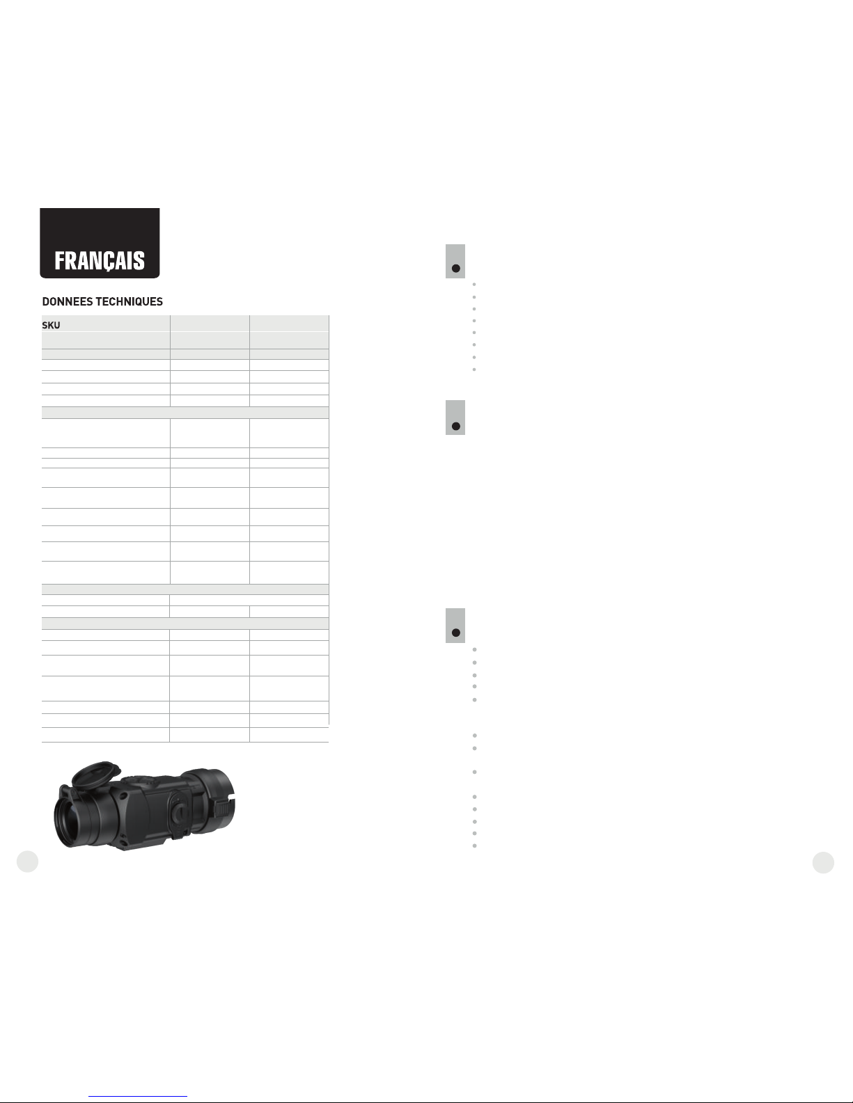
BESCHREIBUNG
CORE ist ein multifunktionales Wärmebildgerät, das entweder als
Monokular oder als Vorsatzgerät betrieben werden kann. Als Vorsatzgerät
wird das CORE auf das Taglichtgerät vorne montiert, um auf das
Tageslichtgerät bei Nacht und Tageslicht auch bei Schlechtwetter (Nebel,
Dunst, Regen) verwendet zu werden.
Als Monokular ermöglicht das CORE ein mehr als 1000 Meter entferntes
Objekt zu beobachten. Im Unterschied zu Nachtsichtgeräten mit
Restlichtröhren braucht das Wärmebildgerät CORE keine Lichtquelle und
ist gegen Seitenbelichtung geschützt. Der Anwendungsbereich des
Wärmebildgerätes umfasst Beobachtung und Geländeorientierung unter
begrenzten Sichtbedingungen, Jagd, Such- und Rettungsmaßnahmen.
MERKMALE
Leicht transformierbar vom Monokular ins Vorsatzgerät
Schnell montierbar
Mehr als 1 Kilometer Zielentdeckung
Kontrastreiches monochromes Display grüner Farbe
Verbesserte Objekterkennung dank der IRIS Technologie (extra
entwickelte Software für die Verbesserung der Bildqualität)
2-faches digitales Zoom des Monokulars
Drei Kalibrierungsmodi: manueller, automatischer,
halbautomatischer
Drei Betriebsmodi: “Felsen”, “Wald”, “Identifizierung”
Drahtlose Fernbedienung
Stabiler Betrieb bei -25…+50 °C
Schutzklasse IPX7 (absolut wasserdicht)
Kompakte Form
Geringes Gewicht
2
Microbolometer:
Type
Bildwechselfrequenz,Hz
Pixelgröße, µm
Auflösung, Pixel
Type
Bildschirm:
Vergrößerung, fach
- Monokular
- Vorsatzgerät
Digitales Zoom, fach
Austrittspupillenabstand des
Monokulars, mm
Austrittspupille des Monokulars, mm
Dioptrienausgleich, Dioptrien
Max. Beobachtungdistanz von einem
Tier 1,7m lang, m
Betriebsparameter:
Schutzklasse, Code IP (IEC 60529)
Abmessungen, mm
Betriebstemperatur, °C
Gewicht (ohne/mit Batterien), kg
Horizontaler Sehfeldwinkel,
m auf 100m
Modell
Betriebsspannung, V
Batterien
Optische Kenndaten:
-25 … +50
ungekühlter
2
384x288
+5/-5
1200
76456
Core FXD50
2,8
1
2
384x288
16
9
+5/-5
1200
IPX7
76454
Core FLD50
5
0,4 / 0,48
19,5
OLED (Green Sapphire)
ungekühlter
25
F50/1.2
Objektiv
LIEFERUMFANG
Änderung des Designs zwecks höherer Gebrauchseigenschaften vorbehalten.
.
Monokular
Okular des Vorsatzgerätes
Aufbewahrungstasche
Trageriemen
Fernbedienungspult
Betriebsanleitung
Putztuch
Garantieschein
1
25
50
2,8
1
F50/1.2
16
5
19,5
Naheinstellung, m
3
3
IPX7
-25 … +50
0,4 / 0,48
Effektive Auflösung, Pixel
12
31
30
640x480
640x480
5 - 7,2 V
5 - 7,2 V
2xCR123A
2xCR123A
190x65x60 190x65x60
Max. Betriebsdauer von einem
Batterie-set, Stunde
4 4

BESTANDTEILE UND STEUERORGANE
4
5
6
7
8
9
10
11
12
1
2
3
4
Objektivschutzdeckel
Objektiv
Rad der inneren Objektivfokussierung
Dioptrienring
Haltering des Okulars
Batteriebehälter
Bajonettring des Okulars des Vorsatzgerätes
Okular des Vorsatzgerätes
Taste “ON/OFF”
Navigationstaste “LEFT”
Navigationstaste “RIGHT”
Taste “MODE”
Taste “ON/OFF” (9)
Taste “LEFT” (10)
Taste “RIGHT” (11)
Taste “MODE” (12)
Steuerorgane:
4
5
1
2
3
6
7
8
9
10
12
11
Erster
Kurzdruck
Nächster
Kurzdruck
Langdruck
Arbeit mit Menü
Kurzdruck
Langdruck
Einschalten
des Gerätes
Kalibrierung
des Gerätes
Ausschalten
des Gerätes
Kalibrierung des Gerätes,
Bestätigung des
Löschens des defekten
Pixels im
entsprechenden
Untermenü
Ausschalten
des Gerätes
Steigerung
der Helligkeit
und des
Kontrasts*
Zoom x2
(nur für das
Monokular)
Navigation im Menü –
nach rechts und nach
oben
Steigerung
der Helligkeit
und des
Kontrasts
Reduzieren
der Helligkeit
und des
Kontrasts*
Abbildungsinversion
Navigation im Menü –
nach links und nach
unten
Aktivierung
der
Bildkontrastein
stellung
Auswahl bestätigen,
das Untermenü
verlassen
Menüeintritt
Auswahl bestätigen**,
das Haupt- und
Untermenü
verlassen
**in einigen Menüs (Uhrzeiteinstellung)
“ON/OFF”
“RIGHT”
“LEFT”
“MODE”
H
A
Halbautomatische Kalibrierung
Automatische Kalibrierung
Ladezustandsanzeige
Uhrzeiteinstellung
Digitales Zoom 2x
Löschen der schadhaften Pixel
Helligkeits- und Kontrasteinstellung
Modus der Abbildungsinversion: “White hot”/“Black hot”
Rückkehr zu Pixelablegen
Helligkeitseinstellung der Menüpiktogramme
5
PIKTOGRAMME DES MENÜS/STATUSZEILE
M
Betriebsmodus “Identifizierung”
Manuelle Kalibrierung
Betriebsmodus “Felsen”
Betriebsmodus “Wald”
Reduzieren
der Helligkeit
und des
Kontrasts*
* gewählt mit der Taste MODE
Aktivierung
der
Bildhelligkeits-
einstellung
12
33
32
Kreuz zum Löschen der schadhaften Pixel

BETRIEB
8
EINLEGEN DER BATTERIEN
7
Dr ehe n Si e den Gri ff d es D eck els des
Batteriefachs (6) gegen den Uhrzeigersinn
gegen den Anschlag. Den Deckel abnehmen.
Le gen Sie z wei B att erien CR1 23A der
Markierung auf dem Deckel des Batteriefachs
und innerhalb des Batteriefachs gemäß ein.
Drehen Sie den Griff des Batteriefachdeckels im
Uhrzeigersinn bis zum Anschlag – die Riegel
werden von den beiden Seiten ausfahren (siehe
Abbildung).
Setzen Sie den Deckel des Batteriefachs zurück
ein, drücken Sie den Deckel bis er einrastet - der
Benutzen Sie nur gleichartige Speiseelemente mit dem gleichen
Aufladeniveau.
8.2. CORE als Vorsatzgerät.
CORE als Vorsatzgerät ermöglicht den Betrieb des Tageslichger tes ä
sowohl am Tag, als auch in der Nacht, auch unter
Schlechtwetterbedingungen (Nebel, Dunst, Regen).
Für den Umbau des Monokulars in das Vorsatzgerät ist es folgende
Vorschriften zu erfüllen:
Schritt 1. Montage des Okulares des Vorsatzgerätes auf das
Wärmebildgerät CORE.
Drehen Sie den Haltering des Okulars (5) gegen Uhrzeigersinn bis ein
Klicken ertönt, nehmen Sie das Okular ab.
Bringen Sie an das Gerät auf folgende das Okular des Vorsatzgerätes
Weise an:
Vergewissern Sie sich, dass sich die Vorsprünge (A) über den unteren
Vorsprüngen befinden (Abb.2).
- Bringen Sie d so unter, dass die Klinkeas Okular des Vorsatzgerätes
(B) (L) dem Logo Pulsar auf dem Gehäuse des Gerätes parallel liegt
(Abb.3)
- Setzen d ins Gehäuse bis zum as Okular des Vorsatzgerätes
Anschlag ein, fixieren Sie ihn durch das Drehen des (7) im Bajonettring
Uhrzeigersinn.
Vor d em B etrie b ve rgewi ss ern Sie sic h, d ass das Gerät lau t
Betriebsanweisungen aus dem Kapitel 8 „Betrieb“ befestigt und eingestellt
wurde.
Lagern Sie das Gerät mit dem geschlossenen Lichtschutzdeckel in der
Aufbewahrungstasche.
Schalten Sie das Gerät nach der Anwendung aus!
Es ist verboten das Garantiegerät zu reparieren und zu demontieren!
Das Gerät kann im breiten Temperaturbereich verwendet werden.
Aber wenn das Gerät von der Kälte in einen warmen Raum gebracht wurde,
nehmen Sie es aus der Aufbewahrungstasche nicht heraus, schalten Sie es
im Laufe von 2-3 Stunden nicht ein. Das ermöglicht die Kondensatbildung auf
den optischen Außenelementen zu vermeiden.
Für ein langes korrektes Funktionieren, Vorbeugung und Beseitigung der
vorzeitigen Störungen und Verschleiß von Bauelementen und – einheiten
führen Sie technische Wartung rechtzeitig durch.
ACHTUNG! Richten Sie das Objektiv des Gerätes niemals direkt auf die
intensiven Lichtquellen, solche wie die Sonne, da die elektronischen
Komponenten beschädigt werden können. Im Rahmen der Garantie
wird für die Schäden nicht gehaftet, die durch falsche Anwendung
verursacht wurden.
BESONDERHEITEN DES BETRIEBS
6
Das Gerät ist für eine dauerhafte Anwendung bestimmt. Um die volle
Leistungsfähigkeit des Gerätes zu gewährleisten, soll man sich an folgende
Empfehlungen halten:
Abb.1
Abb.2
korrekt
falsch
ÖFFNEN:
SCHLIEßEN:
5
8.1. CORE als Monokular.
Die ausführliche Beschreibung des Core Monokulars befindet sich im
Kapitel 9 “EINSTELLUNG DES GERÄTES. KALIBRIERUNG“.
Das Wärmebildgerät kann als Monokular und auch als betrieben werden.
Die Neukonstruktion ermöglicht das Monokular in das Vorsatzgerät schnell
umzubauen.
12
35
34
А
Abb.3
7
Deckel schließt. Vergewissern Sie sich, dass der Deckel beidseitig
geschlossen wurde.
Batterieaufladungszustand wird unten in der Statuszeile ( )
abgebildet. Bei völliger Batterieentladung blinkt das Piktogramm in
der Statuszeile.
Achtung: verwenden Sie keine wieder aufladbaren Batterien – die
Ladezustandsanzeige funktioniert nicht korrekt, das Gerät kann sich
unerwartet abschalten.
B
L

Schritt 3. Montage des Wärmebildgerätes CORE auf das
Taglichtgerät
Setzen Sie das CORE mit dem eingelegten Übergangsring in den Adapter-
Deckel so ein, dass die Stifte im Gehäuse des Adapter-Deckels in die
Rasten des einspringen. Drehen Sie das Okulars des Vorsatzgerätes
Wärmebildgerät CORE entgegen dem Uhrzeigersinn bis ein Knacken
ertönt.
Mithilfe des Sechskantenschlüssels ziehen Sie die Schraube (2 ) an, damit 0
der Adapter mit dem Übergangsring beim Anziehen eng an das Objektiv
des anliegt.Taglichtgeräts
Vor der Montage des Okulars vergewissern Sie sich, dass die oberen
Vorsprünge (C) mit den unteren gelben Vorsprüngen zusammenfallen.
(Abb.5).
Setzen Sie das Okular ins Gehäuse des Gerätes, drehen Sie den Haltering
(5) des Okulars im Uhrzeigersinn.
Schritt 2. Montage des Deckel-Adapters auf das Taglichtgerät
(mithilfe der “Adapter-Deckel DN42/50/56 mm”
(SKU#79124/79125/79126)).
Dem Objektivlinsendurchmesser Ihres Tageslicht s entsprechend gerät
nehmen Sie den Adapter mit Übergangsringen (zusätzlich gekauft) mit
dem passenden Durchmesser.
Die Zeichen 42 mm, 50 mm, 56 mm im Adapternamen bezeichnen die
Größe des Objektivlinsendurchmessers des Tageslicht s.gerät
Messen Sie den Außendurchmesser des Objektivs Ihres Fernrohrs und
wählen Sie den passenden Übergangsring laut der Tabelle.
Beispiel. Wenn der Objektivlinsendurchmesser Ihres Tageslicht sgerät
42 mm beträgt und der ausgemessene Außendurchmesser des
Objektivs 47,2 mm ist, benutzen Sie den Übergangsring mit der
Markierung “Ø 47”.
Kompatibilität der Übergangsringe mit Tageslichtzielfernrohren
Den Deckel (13) entgegen dem Uhrzeigersinn drehend abnehmen.
Setzen Sie den Übergangsring (14) in den Adapter (15) bis zum
Anschlag ein (s. Abb.4)
Der Übergangsring soll mit dem geengten Teil nach vorne
eingelegt werden!
Bringen Sie den Adapter mit dem eingesetzten Übergangsring an das
Objektiv (17) des Tageslichtgerätes an (Abb.4).
Achtung! Vergewissern Sie sich, dass die Linie des Horizonts des
Tageslichtgerätes parallel zum unteren/oberen Rand des
Bildschirmes des Monokulars CORE liegt.
Bringen Sie den Hebel (18) von der Position “AUF” in die Position
„ZU“ (Abb.4).
Vergewissern Sie sich, dass der Adapter an das Objektiv eng anliegt.
Falls die Luft bleibt, sollen Sie folgende Anweisungen befolgen:
richtig
falsch
12
37
36
- Lockern Sie die Halteschraube (19) mithilfe des
Sechskantenschlüssels (S= 2 mm).
- Ziehen Sie die Schraube (20) mit dem Sechskantenschlüssel
(S= 4mm) an, mit einer Klemmkraft, die den Adapter fest auf dem
Objektiv sitzen lässt.
- Ziehen Sie die Halteschraube an (19).
Achtung! Vor der Montage soll das Gehäuse des Objektivs des
Taglichtgerätes und die innere Seite des bergang ringes Ü s
entfettet werden.
Montage des Okulars auf das Wärmebildgerät CORE
Abb.5
Kompatibilität der Übergangsringen für die Tageslichtgeräte
Objektivlinsendurchmesser, mm
Aufsteckdurchmesser des
optischen Geräts, mm
Innendurchmesser
der Übergangsring, mm
42
50
56
59,7-60,6
60,7-61,6
61,7-62,6
60
61
62
62,7-63,6
63
64
63,7-64,6
65
64,7-65,6
46,7-47,6
47,7-48,6
48,7-49,6
47
48
49
49,7-50,6
50
54,7-55,6
55,7-56,6
56,7-57,6
55
56
57
57,7-58,6
58
59
58,7-59,6
45,5
45,5
46
46
46,5
46,5
51,6
51,6
53,4
53,4
С
Fig.4

Anmerkung: das Kalibrierungsintervall hängt vom Heizniveau des
Sensors ab. Beim Einschalten des Gerätes kann das Wärmebildgerät öfter
kalibriert zu werden brauchen.
Öffnen Sie den Objektivschutzdeckel (1).
Dioptrienring (4) drehend, erreichen Sie eine scharfe Abbildung der
Piktogramme in der Statuszeile.
Um das Helligkeitsniveau des Bildschirmes zu optimieren, drücken Sie die
Tasten der Menüführung “LEFT” (10) (Herabsetzung) und “RIGHT” (11)
(Steigerung). Die entsprechende Kontraststufe (von 0 bis 20) wird neben
dem Helligkeitsanzeiger im oberen Teil des Bildschirms gezeigt.
Um das kontrastreiche Bild auf dem Bildschirm zu erreichen, drücken Sie
kurz die Taste “MODE” (12) (es erscheint ein Piktogramm . Drücken Sie
die Tasten der Menüführung “LEFT” (10) (Herabsetzung) und “RIGHT”
(11) (Steigerung). Die entsprechende Kontraststufe (von 0 bis 20) wird
neben dem Kontrastanzeiger im oberen Teil des Bildschirms gezeigt.
Wählen Sie ein unbewegliches warmes Beobachtungsobjekt, das 100
Meter entfernt ist.
Das Fokussierungsrad (3) drehend, erreichen Sie ein möglichst scharfes
Bild.
Nachdem alle Einstellungen durchgeführt wurden, brauchen Sie das
Dioptrienausgleichsrad nicht mehr zu drehen, unabhängig von Distanz und
anderen Bedingungen.
Im aut omatis c h en Regi me w ird das Wä r mebil d g erät de m
Programmalgorithmus nach kalibriert. Der Sensor wird automatisch mit der
Blende geschlossen. In diesem Betriebsmodus ist manuelle Kalibrierung
mittels “ON/OFF” (12) Taste möglich.
Schalten Sie das Gerät ein, öffnen Sie den Objektivschutzdeckel.
Drücken Sie die Taste “MODE” zwei Sekunden lang, um das Menü zu
aktivieren.
Wählen Sie den Menüpunkt Cal, indem Sie die Tasten der Menüführung
“LEFT” (10) und “RIGHT” (11) anwenden.
Wählen Sie den Modus “A”. Um die Auswahl zu bestätigen, drüсken Sie
die Taste “MODE”.
Bei der automatischen Kalibrierung erstarrt das Bild für eine oder zwei
Sekunden. Es ertönt ein Geräusch durch das Funktionieren der inneren
Blende.
EINSTELLUNG DES GERÄTES. KALIBRIERUNG.
9
Öffnen Sie den Objektivschuztdeckel (1).
Schalten Sie das Gerät ein, indem Sie die Taste “ON/OFF” (9) kurz
drücken. Halten Sie die Taste “MODE” (12) zwei Sekunden lang gedrückt,
um ins Menü zu übergehen.
Wählen Sie den Menüpunkt Cal, indem Sie die Tasten der Menüführung
“LEFT” (10) und “RIGHT” (11) anwenden. Wählen Sie den Modus “М”.
Um die Auswahl zu bestätigen, drüсken Sie die Taste “MODE”. Um das
Menü zu verlassen, halten Sie die Taste zwei Sekunden lang gedrückt,
oder warten Sie 10 Sekunden ab - das Menü wird automatisch deaktiviert.
Schließen den Objektivschutzdeckel (1). Um den Sensor zu kalibrieren,
drücken Sie die Taste “ON/OFF”. Das Bild erstarrt für eine oder zwei
Sekunden. Danach ist der Objektivschutzdeckel zu öffnen. Das Kalibrieren
verlief erfolgreich.
Falls auf dem Display Fehler auftreten (erstarrtes Bild, senkrechte Linien
u.ä.), soll die Kalibrierung wiederholt werden.
Schalten Sie das Gerät ein, öffnen Sie den Objektivschutzdeckel.
Halten Sie die Taste “MODE” (12) zwei Sekunden lang gedrückt, um das
Menü zu aktivieren.
Wählen Sie den Menüpunkt Cal, indem Sie die Tasten der Menüführung
“LEFT” (10) und “RIGHT” (11) anwenden.
Wählen Sie den Modus “H”. Um die Auswahl zu bestätigen, drüсken Sie
die Taste “MODE”.
Um den Sensor zu kalibrieren, drücken Sie die Taste “ON/OFF”. Das Bild
erstarrt für eine oder zwei Sekunden, dabei wird die innere Blende ein
Geräusch angeben. Das Gerät wurde erfolgreich kalibriert.
Schalten Sie das Gerät ein, indem Sie die Taste “ON/OFF” (9) drücken.
Wenn die Batterie entladen ist, leuchtet der Anzeiger rot und das
Piktogramm beginnt zu blinken.
Kalibrieren Sie das Bild. Das ermöglicht den Wärmegrad des
Mikrobolometers auszugleichen und Fehler der Abbildung zu beheben.
Das Gerät bietet drei Kalibrierungsmodi an:
Manuellen (M), halbautomatischen (H) und automatischen (A).
Betriebsmodus “Mode”
Kalibrierungsmodi
Helligkeitseinstellung
der Menüpiktogramme
Uhrzeiteinstellung
Aktivierung der Fernbedienung
Löschen der schadhaften Pixel
MENÜ
10
Das Menü besteht aus folgenden Punkten:
Statuszeile
In der Statuszeile wird folgende Information abgebildet:
Betriebsmodus (“Felsen”, “Wald”, “Identifizierung”)
Kalibrierungsmodus (manueller, automatischer, halbautomatischer)
Helligkeitseinstellung der Menüpiktogramme
Zweifache Vergrößerung eingeschaltet (“Zoom”)
“Abbildungsinversion” aktiviert
Gleitzeit
Batteriestand
Betriebsmodus
Das Wärmebildgerät bietet drei automatische Betriebsmodi an:
“Felsen” (hohes Kontrastniveau), “Wald” (niedriges Kontrastniveau)
und “Identifizierung” (erhöhte Detaillierung).
Jedes Regime hat optimales Verhältnis der Betriebsparameter (Helligkeit,
Kontrast, Intensität usw.), was die beste an die Beobachtungsbedingungen
angepasste Bildqualität garantiert.
12
39
38
Manuelle (geräuschlose) Kalibrierung
Halbautomatische Kalibrierung
Automatische Kalibrierung
Fokussierung und Einstellung des Bildes

Kalibrierungsmodi
S. Kapitel 8 “Betrieb”.
Halten Sie die Taste “MODE” (12) zwei Sekunden lang gedrückt, um das
Menü zu aktivieren.
Wählen Sie das Piktogramm mit den Tasten der Menüführung “LEFT”
(10) und “RIGHT” (11). Drücken Sie die Taste “MODE”.
Drücken Sie die Tasten der Menüführung, um das Helligkeitsniveau der
Piktogramme einzustellen (von 1 bis 10).
Um das Menü zu verlassen, halten Sie die Taste “MODE” zwei Sekunden
lang gedrückt, oder es ist 10 Sekunden abzuwarten, es erfolgt der Ausgang
aus dem Menü automatisch.
Drücken Sie die Taste “MODE” (12) zwei Sekunden lang, um das Menü zu
aktivieren.
Wählen Sie das Piktogramm mit den Tasten der Menüführung (10) und
(11). Drücken Sie die Taste “MODE”.
Bewegen Sie den Blinker mit den Tasten der Menüführung, um das
Uhrzeitformat zwischen “24” und “AM/PM” zu wählen.
Drücken Sie die Taste “MODE”, um den Stundenwert einzugeben. Benutzen
Sie dafür die Tasten der Menüführung. Drücken Sie die Taste “MODE”, um
den Minutenwert einzugeben. Benutzen Sie dafür die Tasten der
Menüführung.
Um das Menü zu verlassen, halten Sie die Taste “MODE” zwei Sekunden
lang gedrückt, oder es ist 10 Sekunden abzuwarten, so erfolgt der Ausgang
aus dem Menü automatisch.
Während des Betriebs können auf dem Sensor des Wärmebildgerätes
schadhafte Pixel (das Bild störende, stabil leuchtende helle oder dunkle
Punkte) erscheinen. Dabei ist es möglich, in den CORE Geräten die
schadhaften Pixel durch extra Programm zu löschen.
Drücken Sie die Taste “MODE” (12) zwei Sekunden lang, um das Menü zu
aktivieren.
Wählen Sie das Piktogramm mit den Tasten der Menüführung (10) und
“RIGHT” (11). Drücken Sie die Taste “MODE”.
Im Untermenü wählen Sie das Piktogramm . Drücken Sie die Taste
“MODE”.
Im Zentrum des Bildschirms erscheint ein Kreuz , wo die Bildsymbole
auftauchen, erscheinen relativ dem Kreuz des Displayzentrums
Koordinaten (X;Y) , die Piktogramme des Menüs verschwinden.
Das Kreuz soll mit den Tasten der Menüführung so bewegt werden, dass
das Zentrum des Kreuzes mit dem schadhaften Pixel verschmilzt (bei der
richtigen Verschmelzung der schadhafte Pixel erlischt). Ein kurzes
Dr ücken der Taste “MODE ” er mö glich t da s Umsc halte n der
Bewegungsrichtungen des Kreuzes von der senkrechten auf die
waagerechte.
Nachdem das Kreuzzentrum den schadhaften Pixel abgedeckt hat, wird
der gewählte Pixel durch das kurze Drücken der Taste “ON/OFF” (9)
gelöscht.
Wenn das Löschen erfolgreich gelaufen ist, erscheint an der Stelle, wo
Koordinaten waren, eine “OK” Mitteilung.
Drahtloses Fernbedienungspult wiederholt die Einschaltfunktion des
Gerätes, Bildinversion, und Kalibrierung.
Auf dem Fernbedienungspult gibt es drei Tasten:
Taste “ON” (22) – das Gerät ein-/ ausschalten
(einschalten – Kurzdruck/ ausschalten –
Dauerdrücken (2 Sekunden)).
Taste (23) - Farbinversion des Bildes
Taste “CAL” (24) – Kalibrierung.
Vor dem Gebrauch des Fernbedienungspultes
aktivieren Sie es auf folgende Weise:
Wählen Sie den Menüpunkt „Aktivieren des
Fernbedienungspultes“ (Piktogramm )
Drücken Sie die Taste “MODE” (12), es erscheint die Mitteilung “Wait”
(warten) und der Countdown fängt an, so soll im Laufe von dieser Zeit eine
von den Tasten des Fernbedienungspultes zwei Sekunden gedrückt gehalten
werden.
Die Mitteilung “Complete” erscheint neben dem Piktogramm wenn die
Aktivierung erfolgreich gelaufen ist.
X=50
Y=50
Drücken Sie kurz die Taste “MODE”, um die Auswahl zu bestätigen.
Das Piktogramm des gewählten Modus wird in der Statuszeile abgebildet.
12
41
40
Helligkeitseinstellung der Menüpiktogramme
Uhrzeiteinstellung
Aktivierung der Fernbedienung
Löschen der schadhaften Pixel
Drücken Sie die Taste “MODE” (12) zwei Sekunden lang, um das Menü zu
aktivieren,
Wählen Sie den Punkt “Betriebsmodi” mit den Tasten der Menüführung
“LEFT” (10) und “RIGHT” (11).
Wenn das Fernbedienungspult nicht funktioniert, setzen Sie eine neue
Batterie ein. Dafür schrauben Sie die Schrauben von der Rückwandplatte
des Fernbedienungspultes ab, nehmen Sie die abnehmbare Rückwand ab,
nehmen Sie die entladene Batterie heraus und legen Sie eine neue Batterie
CR2032 hinein.
Rückstellung zu „Pixelablegen“
Um „Pixelablegen“ zurückzubekommen (alle gelöschten schadhaften
Pixel in Ausgangszustand zu bringen), ist es das im Untermenü
aufgetauchte Piktogramm zu wählen und die Taste “MODE” (12)
drücken.
Rechts vom Piktogramm erscheinen Punkte “Yes” und “No”.
Wählen Sie “Yes” mit den Tasten der Menüführung und drücken Sie die
Taste “MODE”.
Falls Sie „Pixelablegen“ doch nicht brauchen, wählen Sie “No”, drücken
Sie die Taste “MODE”.
Um das Menü zu verlassen, halten Sie die Taste zwei Sekunden lang
gedrückt, oder es ist 10 Sekunden abzuwarten, so erfolgt der Ausgang
aus dem Menü automatisch.
Anmerkung! Auf dem Bildschirm des Wärmebildgerätes sind einer
oder zwei Pixel als weiße oder schwarze Punkte zulässig. Diese
können nicht entfernt werden, dabei stellen Sie kein Defekt dar.
Das Kreuz bewegend, kann man auch weitere schadhafte Pixel löschen.
Falls das Kreuz an die Stelle gebracht wird, wo die Koordinaten auf dem
Bildschirm abgebildet werden, werden die Koordinaten in den rechten
unteren Teil des Displays verschoben.
Um den Menüpunkt „Löschen der Schadenpixel“ zu verlassen, halten
Sie die Taste “MODE“ zwei Sekunden lang gedrückt.
24
23
22

WARTUNG UND LAGERUNG
11
Das Gerät hat Schutzklasse IPX7 (absolut wasserdicht – Schutz beim
Eintauchen einen Meter tief für 30 Minuten).
Es ist verboten das Gerät zu reparieren und zu demontieren!
Reinigen Sie die optischen Außenteile sehr vorsichtig und nur im Falle der
dringenden Notwendigkeit. Zuerst entfernen (wischen oder abstäuben) Sie
vorsichtig den Staub und Sand von der optischen Oberfläche, dann reinigen
Sie sie. Benutzen Sie ein sauberes Baumwolltuch (Watte mit Holzstab), die
speziellen Mittel für die Linsen mit den Vielfachschichten oder Spiritus.
Gießen die Flüssigkeit nie direkt auf die Linse!
Lagern Sie das Gerät immer nur in der Aufbewahrungstasche, in einem
trockenen, gut gelüfteten Raum. Bei der Dauerlagerung ziehen Sie
unbedingt die Batterien heraus.
12
FEHLERBESEITIGUNG
In der Tabelle ist die Liste der möglichen Probleme, die beim Betrieb des
Gerätes auftreten können, aufgeführt. Führen Sie die empfohlene Prüfung und
Korrektur auf Art und Weise, wie es in der Tabelle angeführt ist, durch. In der
Tabelle sind nicht alle Probleme, die entstehen können, erwähnt. Wenn in der
gegebenen Liste das Problem nicht genannt ist, oder die erwähnte Maßnahme
für die Beseitigung des Defektes kein Ergebnis hat, teilen Sie darüber dem
Hersteller mit.
Problem
Mögliche Ursache Beseitigung
Das Gerät kann nicht
eingeschaltet werden.
Da s Bild ist uns cha rf ,
mi t sen kre ch te n Lin ien
verzerrt und der Hintergrund
ist ungleichmäßig.
Batterien sind falsch
eingelegt.
Die Kontakte im Batteriebehälter
oder auf dem Deckel
sind oxidiert: die Batterie läuft oder
die Kontakte wurden durch
chemisch aktive Flüssigkeit
beschädigt.
Batterien sind leer.
Das Gerät soll kalibriert werden.
Legen Sie Batterien der Markierung
entsprechend ein.
Reinigen Sie die Kontakte im Innern
des Batteriebehälters oder auf
seinem Deckel.
Legen Sie neue Batterien ein.
Führen Sie das Kalibrieren der
Abteilung 9 entsprechend
durch.
Das Bild ist zu dunkel.
Die Helligkeit des Bildes ist auf
niedrigem Niveau.
Stellen Sie die Helligkeit des
Bildschirms ein.
12
43
42
Andere Funktionen
Um das 2-fache digitale Zoom zu aktivieren (nur bei der Handanwendung),
drücken Sie die Taste “RIGHT” (11) zwei Sekunden lang. In der Statuszeile
erschein das Piktogramm .
Um die Farbinversion des Bildes (Funktionen “White hot” und “Black hot”)
zu aktivieren, halten Sie die Taste “LEFT” (10) zwei Sekunden lang
gedrückt. Falls die Funktion “White hot” („Weiß heiß“) ein ist, werden
warme Objekte in helleren Farbtönen dargestellt; im Modus “Black hot”
(Schwarz heiß) werden warme Objekte in dunkleren Farbschattierungen
gezeigt.
Um das Gerät auszuschalten, halten Sie die Taste “ON/OFF” (9) zwei
Sekunden lang gedrückt.
Der Batteriefachdeckel ist locker
geschlossen.
Schließen Sie den Deckel fest.
Der Treffpunkt fällt mit dem
Zielpunkt nicht zusammen.
Das Display soll kalibriert werden.
Das Display soll laut Betriebsanleitung
kalibriert werden (s. unten).
Kalibrierung des Displays
Halten Sie zwei Sekunden lang die Tasten “LEFT” (10) und “MODE” (12)
oder (23) und (24) der Fernbedienung gleichzeitig gedrückt, um in das
zusätzliche Menü zu gehen. Mit den Tasten
“L EFT” (1 0) o der “RIGH T”(11) w äh len Sie den Men üp unk t
“Kalibrierung des Displays” . Zur Bestätigung drücken Sie “MODE”.
Auf dem Display erscheint ein Einschießkreuz im Begrenzungsrahmen
und Symbole .
Schieben Sie das Be grenzungsrahmen mit dem Einschießkreuz
waagerecht mit den Tasten “LEFT” oder “RIGHT” (oder (22), (24) auf
dem Fernbedienungspult). Die Verschiebung erfolgt sowohl beim kurzen,
als auch beim langen Drücken. Um die Richtung von der waagerechten
auf die senkrechte umzuschalten, “MODE” drücken.
Halten Sie die Taste “MODE” (oder die Taste (23) der Fernbedienung)
zwei Sekunden lang gedrückt. Neben dem Piktogramm erscheint die
Ziffer “2” und die Pfeile mit Koordinatenwerten X und Y .
Das Absehen im Zielpunkt haltend, bringen Sie das Einschießkreuz in die
Treffpunktlage. Benutzen Sie die Tasten “LEFT” und “RIGHT” (oder (22),
(24) auf d em Fe rnbed ie nungspu lt ). Um di e Richtun g von d er
waagerechten auf die senkrechte umzuschalten, wählen Sie die Taste
“MODE” oder die Taste (23) des Fernbedienungspultes.
Schieben Sie das Einschießkreuz waagerecht mit den Tasten “LEFT”
und “RIGHT” (oder (22), (24) auf dem Fernbedienungspult). Der Bereich
der Verschiebung relativ dem Begrenzungsrahmen beträgt waagerecht
und senkrecht +/-10.
Schließlich soll das Einschießkreuz mit dem Treffpunkt zusammenfallen,
dabei soll das Absehen im Zielpunkt gehalten werden.
Um die Einstellungen des Einschießens zu speichern, halten Sie die Taste
“MODE” oder die Taste (23) des Fernbedienungspultes zwei Sekunden
lang gedrückt. Auf dem Display erscheint die Mitteilung “OK”, und Sie
verlassen das Menü. Die Abbildung des Mittelpunktes des Absehens fällt
mit dem M ittel punkt de s Abseh en s des Tag eslic htzie lfern ro hrs
zusammen.
Um Werkeinstellungen wiederherzustellen, wählen Sie “Yes” im
gleichnamigen Menüpunkt .
Folgende Einstellungen werden zum Anfangszustand gebracht:
Betriebsmodus – “Wald” ;
Kalibrierungsmodus – automatisch;
Helligkeitseinstellung der Grafik - 5;
Kalibrierung des Displays - Koordinatenwerte X=0, Y=0;
Vergrößerung - x1;
Bildinversion – ausgeschaltet;
Helligkeitseinstellung – 10;
Kontrasteinstellung – 6.
Anmerkung. Der Zugang zum zusätzlichen Menü (Menüpunkte
„Kalibrierung des Displays“, „Werkeinstellungen wiederherstellen“)
ist nur während des Betriebes als Vorsatzgerät möglich.

CARACTERÍSTICAS TÉCNICAS
3
DESCRIPCIÓN
El CORE es un dispositivo térmico multifuncional que puede ser utilizado
como un monocular o como un visor acoplable. El CORE como visor
acoplable se utiliza con dispositivos diurnos tanto de noche como de día,
con condiciones atmosféricas complejas (nieble, smog, lluvia), así como
también cuando existen obstáculos que dificultan la detección del objetivo
(ramas, hierva alta, arbustos densos, etc.).
El CORE como monocular permite al usuario observar un objeto a una
distancia más de 1000 metros. A diferencia de los dispositivos de visión
nocturna sobre la base de convertidores electrónico-ópticos, los
dispositivos CORE no necesitan una fuente externa de luz y no les afecta
las las "sobreexposiciones" de luz. Los dispositivos CORE pueden
emplearse para la caza nocturna, la observación y orientación sobre el
terreno, y la realización de operaciones de rescate y salvamento.
PARTICULARIDADES DISTINTIVAS
Conversión rápida del monocular al visor acoplable (2 en 1)
Montaje y desmontaje rápido del visor acoplable
Distancia máxima de detección de más de 1km
Pantalla verde monocromo de elevado contraste
Software de alto reconocimiento y detección (tecnología IRIS)
(basado en algoritmo intelectual de la ecualización dinámica)
Zoom digital de 2x aumentos para el monocular
Tres regímenes de calibración - manual, automático, semiautomático
Tres regímenes de funcionamiento – “Rocas”, “Bosque”,
“Reconocimiento”
Mando control remoto
Rango de temperaturas de uso -25 °C a +50°C
Grado de protección IPX7 (totalmente hermético al agua)
Tamaño compacto
Peso ligero
2
Microbolómetro:
Tipo
Frecuencia de la renovación
de las imágenes, Hz
Tamaño del pixel, µm
Resolución, pixel
Tipo
La pantalla:
Aumentos, x
- monocular
- visor acoplable
Zoom digital, x
Alivio pupilar del monocular, mm
Diámetro de la pupila de salida
del monocular, mm
Ajuste dióptrico del ocular, dioptrias
Distancia máxima de observación
de un animal 1,7m de largo, m
Características de empleo:
Clase de protección, código IP
(IEC 60529)
Temperatura de trabajo, °C
Peso (sin/con baterías), kg
Ángulo horizontal del campo de
visión, m a 100m
Model
Alimentación
Tipo de baterias
Características ópticas:
-25 … +50
no refrigerado
2
384x288
+5/-5
1200
76456
Core FXD50
2,8
1
2
384x288
16
9
+5/-5
1200
IPX7
76454
Core FLD50
5
0,4 / 0,48
19,5
OLED (Green Sapphire)
no refrigerado
25
F50/1.2
Objetivo
CONTENIDO DEL EMBALAJE
Con el fin de mejorar el diseño del producto, este puede estar sujeto a cambios.
Monocular CORE
Ocular del visor acoplable
Funda
Correa para la mano
Control remoto inalámbrico
Manual de usuario
Paño de limpieza
Tarjeta de garantía
1
25
50
2,8
1
F50/1.2
16
5
19,5
Distancia mínima del enfoque, m
3
3
IPX7
-25 … +50
0,4 / 0,48
45
44
Resolución, pixel
640x480640x480
5 - 7,2 V
5 - 7,2 V
2xCR123A
2xCR123A
Dimensiones, mm
190x65x60 190x65x60
Tiempo operativo con juego
de baterías, h
4 4

ELEMENTOS Y ÓRGANOS DE MANDO
4
5
6
7
8
9
10
11
12
1
2
3
4
Tapa del objetivo
Objetivo
Manilla del enfoque interno del objetivo
Anilla del ajuste dióptrico del ocular
Anilla de bloqueo del ocular
Tapa del contenedor de las baterías
Anilla de tipo bayoneta del ocular del visor acoplable
Ocular del visor acoplable
Botón “ON/OFF”
Botón de navegación “LEFT”
Botón de navegación “RIGHT”
Botón “MODE”
Botón “ON/OFF” (9)
Botón “LEFT” (10)
Botón “RIGHT” (11)
Botón “MODE” (12)
Órganos de control:
4
5
1
2
3
6
7
8
9
10
12
11
Primera
presión breve
Siguiente
presión breve
La presión
larga
Operación en el menú
Presión Breve
Presión Larga
Encender
el dispositivo.
Calibración
del dispositivo.
Apagar
el dispositivo.
Calibración del
dispositivo,
confirmación
de la eliminación
de píxeles defectuosos
- en el submenú
correspondiente.
Apagar el dispositivo.
El aumento
de nivel de
luminosidad
y el contraste*.
Zoom digital
x2
(solamente
para el
monocular).
Navegación por el
menú – hacia arriba
y hacia la derecha
El aumento
de nivel de
luminosidad
y el contraste.
La reducción
de nivel de
luminosidad
y del contraste.
Inversión
de la imagen.
Navegación por el
menú – hacia abajo
y hacia la izquierda.
Activación
del modo
de control
de contraste.
Activación del
modo de
control de
luminosidad.
Confirmación
y salida del menu.
Acceso
al menu.
Confirmación
y salida del
submenú**, salida
del menú principal
y complementario.
**en ciertos submenús (ajuste del reloj).
“ON/OFF”
“RIGHT”
“LEFT”
“MODE”
H
A
Regímen de la calibración semi-automático
Regímen de la calibración automático
Indicación de la carga de las baterías
Régimen del ajuste del reloj
Zoom digital 2x
La función de eliminación de píxeles defectuosos
Ajuste del nivel de luminosidad y contraste
Regímen de inversión de imagen: “White hot”/“Black hot”
La cruz para eliminar píxeles defectuosos
Vuelta a la mapa de píxeles original
Ajuste de la luminosidad de los iconos del menú
5
ICONOS DE MENÚ/BARRA DE ESTADO
M
Regímen de funcionamiento “Reconocimiento”
Regímen de la calibración manual
Regímen de funcionamiento “Roscas”
Regímen de funcionamiento “Bosque”
La reducción
de nivel
de luminosidad
y del contraste.
47
46
* dependiendo del modo seleccionado
con el botón MODE

8.1. El CORE como monocular
La descripción detallada del monocular CORE se puede encontrar en la
sección 9 "EMPLEO. CALIBRACIÓN".
EMPLEO
8
INSTALACIÓN DE BATERÍAS
7
Gire la manilla de la tapa (6) del compartimiento
de pilas en el sentido de las agujas del reloj hacia
el tope y quite la tapa.
Instale dos baterías del tipo CR123A según la
indicación de fuera y dentro de la tapa del
compartimiento de pilas.
Gire la manilla de la tapa (6) del compartimiento
contra el tope – los linguetes de bloqueo aparecen
de ambos lados (ver la figura).
Coloque la tapa del compartimiento de pilas y
presione hasta un clic - asegúrese que la tapa
está cerrada de ambos lados.
El nivel de carga se muestra en la barra de
estado.
El CORE se puede utilizar como un monocular térmico o un visor acoplable
a un visor diurno. El diseño original le permite convertir rápidamente el
monocular en visor acoplable y viceversa.
Nota: no use las baterías de tipos diferentes o baterías con diferentes
niveles de carga.
8.2. El CORE como visor acoplable
El CORE está diseñado para usarlo con un tanto de dispositivo diurno
noche, como de día, incluso en condiciones atmosféricas complejas
(nieble, smog, lluvia).
Para convertir el monocular en un visor acoplable y montarlo en
dispositivo diurno siga, por favor, las instrucciones siguientes:
Etapa 1. Montaje del adaptador en el monocular CORE
Gire la anilla de bloqueo (5) del ocular en el sentido contrario a las
agujas del reloj hasta que oiga un clic y desmonte el ocular (Fig.1).
Monte en el monocular del modo el ocular del visor acoplable
siguiente:
- Asegúrese de que los salientes (A) del adaptador se encuentran por
encima de los salientes inferiores (Fig. 2).
- Coloque de modo que la cerradura (B) es el ocular del visor acoplable
paralela al logotipo Pulsar (L) en el cuerpo del monocular (Fig.3).
- Inserte en el cuerpo del monocular hasta el el ocular del visor acoplable
fin y fíjelo girando la a (7) en sentido de las agujas nilla de tipo bayoneta
del reloj.
Antes del uso del visor, asegurese de que el dispositivo fue ajustado y
instalado conforme a la sección 8 “Empleo”.
Siempre hay que conservar el dispositivo con la tapa del objetivo cerrada
solamente en la funda, en un local seco, con ventilación.
Apague el instrumento después de su uso.
Se prohibe reparar o desarmar el visor cuando está en periodo de
garantía!
El dispositivo se puede utilizar dentro de un amplio rango de temperaturas.
Sin embargo, si el dispositivo ha sido introducido desde el frío a un local
abrigado - no lo encienda en el curso de 2 a 3 horas.
Para garantizar un funciónamiento impecable, lleve a cabo una revisión
técnica y el mantenimiento del dispositivo.
GUÍAS DE OPERACIÓN
6
Para asegurar el uso prolongado del visor, tenga en cuenta las siguientes
recomendaciones:
L
B
Fig.1
Fig.2
Fig.3
CORRECTO
INCORRECTO
ABRIR:
CERRAR:
5
ADVERTENCIA! No dirija el dispositivo a fuentes de luz intensos, como el sol. Esto
puede deshabilitar los componentes electrónicos de la unidad. La garantía no cubre
los daños causados por el uso incorrecto o manipulación del aparato.
49
48
А
Si las baterías descargan completamente, el pictograma parpadea
en la barra de estado.
Atención: no use baterias recargables, su uso causa la indicación del
ni ve l de c ar go i nc or re ct a y el dispositivo puede apagarse
inesperadamente durante su funcionamiento.

Etapa 3. Instalar el CORE en el dispositivo diurno
Inserte firmemente el CORE con montado en el el ocular del visor acoplable
tapa-adaptador de tal manera que los dientes en el cuerpo del adaptador
entren en las ranuras del . Gire la unidad Core a la ocular del visor acoplable
izquierda hasta escuchar un clic.
Apriete el tornillo (2 ) con llave hexagonal, para asegurarse que al 0 una
girar la palanca, el adaptador con el casquillo encaja bien en el objetivo del
dispositivo diurno.
Para montar el ocular en el CORE, asegúrese de que los salientes
inferiores (C) del ocular coinciden con los salientes amarillas inferiores
(Fig. 5).
Inserte el ocular en el cuerpo del monocular y gire el anillo de bloqueo (5)
hacia la derecha (o en el sentido de las agujas del reloj).
Etapa 2. Instalar la Tapa-adaptador en dispositivo diurno (usando
las Tapas-adaptadores DN42/50/56 mm metálicos)
(SKU#79124/79125/79126)
Seleccione un adaptador con un casquillo (comprado por separado) del
diámetro necesario. Debe elegirlo en función de la medida del diámetro
exterior del objetivo de su . dispositivo diurno
Una inscripción - 42 mm, 50 mm o 56 mm - en el adaptador designa el
diámetro de luz del objetivo del . dispositivo diurno
Mida el diámetro exterior del cuerpo del objetivo de su dispositivo diurno
y elija el casquillo de acuerdo a la medida indicada en las tablas.
Ejemplo: si el diámetro de luz de su dispositivo es fuera de 42mm, y la
medida exterior del objetivo es fuera de 47,2 mm, utilice el casquillo
marcado con “Ø 47”.
Saque la tapa (13) del adaptador girándola en el sentido inverso a las
agujas del reloj.
Instale el casquillo (14) en el adaptador (15) hasta el final (ver. Fig.4).
Importante! El casquillo debe instalarse con la parte angosta hacia
adelante (ver el esquema).
Instale por completo el adaptador con el casquillo sobre el objetivo (17)
del visor diurno (ver. Fig.4).
Cambie la palanca (18) de la posición inicial “ABIERTO” a la posición
“CERRADO” (ver. Fig.4).
Verifique que el adaptador encaja bien sobre el objetivo. Si no fuese así
y tuviese alguna holgura, haga lo siguiente:
51
50
¡Atención! Antes de la instalación se recomienda engrasar el
cuerpo del dispositivo diurno y la superficie interna del casquillo.
- Afloje el tornillo de bloqueo (19) con la llave hexagonal (S=2 mm).
- Apriete el tornillo (20) con una llave para hexagonal (S=4 mm) con el
esfuerzo de apriete, necessario para asegurar que el adaptador esté
bien ajustado al objetivo.
Apriete el tornillo (19).
Instalar el ocular en el CORE
Diámetro de la lente
del dispositivo diurno, mm
El diámetro externo del
cuerpo del objetivo del
dispositivo diurno, mm
El diámetro interno
del casquillo, mm
La tabla de la compatibilidad de los casquillos y los dispositivos diurnos
42
50
56
59,7-60,6
60,7-61,6
61,7-62,6
60
61
62
62,7-63,6
63
64
63,7-64,6
65
64,7-65,6
46,7-47,6
47,7-48,6
48,7-49,6
47
48
49
49,7-50,6
50
54,7-55,6
55,7-56,6
56,7-57,6
55
56
57
57,7-58,6
58
59
58,7-59,6
45,5
45,5
46
46
46,5
46,5
51,6
51,6
53,4
53,4
CORRECTO
INCORRECTO
Fig.5
С
abierto
cerrado
Atención! Asegúrese que la línea de horizonte del dispositivo
diurno está paralelo al borde superior/inferior de la pantalla del
monocular CORE.
Fig.4

Enfoque y ajuste de la imagen
Abra la tapa (1) del objetivo.
Ajuste la nitidez de los pictogramas por medio de la rotación del anillo de
ajuste dióptrico del ocular (4).
Para ajustar la luminosidad de la pantalla, pulse brevemente botónes de
navegación - “LEFT” (10) (reducción) y “RIGHT” (11) (aumento). El grado
de luminosidad seleccionado (de 0 a 20) aparece junto con el pictograma
en la esquina superior derecha de la pantalla.
Para ajustar el contraste de la pantalla, pulse brevemente el botón
“MODE” (12) (aparece el pictograma ). Pulse brevemente los botónes
de navegación - “LEFT” (10) (reducción) y “RIGHT” (11) (aumento). Para
seleccionar el nivel del contraste level (de 0 a 20). El grado correspondiente
de contraste aparece junto con el pictograma de contraste en la esquina
superior derecha de la pantalla.
Elija un objeto cálido inmóvil para la observación que esté alejado a una
cierta distancia, por ejemplo, 100 m.
Girando la rueda del enfoque interno del objetivo (3), obtenga la mejor
calidad de la imagen.
Después de éste ajuste, independientemente de la distancia y de otras
condiciones, no hay necesidad de girar el anillo del ajuste dióptrico. Ajuste
la imagen solamente con la rueda del enfoque interno del objetivo.
En el regimen de calibración automática el dispositivo se calibra de forma
independiente de acuerdo con el algoritmo del programa. El sensor se
cierra por la compuerta interna automáticamente. En éste regímen se
permite la calibración manual usando el botón “ON/OFF”.
Encienda el dispositivo, abra la tapa del objetivo.
Mantenga pulsado el botón “MODE” (12) por dos segundos para entrar en
el menú.
Use los botónes de navegación “LEFT” (10) y “RIGHT” (11) para
seleccionar la opción Cal. Seleccione el modo A. Pulse el botón “MODE”
para confirmar.
En el momento de calibración automatica la imagen se hiela durante 1-2
segundos. Ud. va a oir el sonido de la compuerta interno.
Nota: el tiempo entre las calibraciones depende de calentamiento del
sensor. Al encender el dispositivo, la calibración puede tener lugar más
frecuentemente.
EMPLEO. CALIBRACIÓN
9
Abra la tapa del objetivo (1).
Pulse brevemente el botón “ON/OFF” (9) para encender el dispositivo,
mantenga pulsado el botón “MODE” (12) dos segundos para entrar en el
menú.
Use los botónes de navegación “LEFT” (10) y “RIGHT” (11) para
seleccionar el punto Cal. Seleccione el modo M. Pulse el botón MODE para
confirmar. Para salir del menú, mantenga pulsado el botón MODE dos
se gundo s o esper e unos 10 s egund os – la sa lida oc urrir á
automáticamente.
Cierre la tapa del objetivo. Pulse brevemente el botón “ON/OFF” para
calibrar. La imagen se congela durante 1-2 segundos. Luego abra la tapa
del objetivo. La calibración está terminada.
Si en la pantalla aparecen defectos de la imagen (imagen congelada, rayas
verticales etc.) vuelva a calibrar de nuevo con la tapa del objetivo cerrada.
Enciende el dispositivo, abra la tapa del objetivo.
Mantenga pulsado el botón “MODE” (12) por dos segundos para entrar en
el menú.
Use los botónes de navegación “LEFT” (10) y “RIGHT” (11) para
seleccionar la opción Cal. Seleccione el modo H. Pulse el botón MODE
para confirmar.
Pulse brevemente el botón “ON/OFF” para calibrar. La imagen se congela
durante 1-2 segundos. Ud. va a oir el sonido de la compuerta interna. La
calibración está terminada.
Pulse brevemente el botón “ON/OFF” (9) para encender el visor. En el
caso de una descarga completa de las baterías el pictograma parpadea
en la barra de estado.
Lleve a cabo la calibración de la imagen. La calibración permite equilibrar
el fondo de temperaturas del microbolómetro y eliminar los defectos de la
imagen.
Hay tres regímenes de calibración: manual (M), semi-automático (H) y
automático (А).
Régimenes de funcionamiento
Régimenes de calibración
Ajuste de luminosidad de
símbolos de pantalla
Reglaje de reloj
Activación del control
remoto inalámbrico
Eliminación de píxeles defectuosos
MENÚ
10
El menú contiene las opciones siguientes:
La barra de estado
En la barra de estado se muestra la siguiente información:
Regímen de funcionamiento – “Rocas”, “Bosque”, “Reconocimiento”
Regímen de la calibración - manual, automático, semi-automático
Zoom digital x2 activado
Inversión de la imagen activado
Reglaje de reloj
Estado de la batería
53
52
Regímen de calibración manual (silencioso)
Regímen de calibración semi-automático
Regímen de calibración automática
Mantenga pulsado el botón “RIGHT” (11) durante dos segundos para
activar el zoom digital de 2x (disponible solamente si el dispositivo está
usado como monocular). El pictograma aparece en la barra de
estado.
Mantenga pulsado el botón “LEFT” (10) dos segundos para activar la
inversión del color de la imagen (funciones “White hot” y “Black hot”). Al
utilizar la función “White hot” (blanco cálido) los objetos cálientes se
representan con matices más claros; “Black hot” (negro cálido) – los
objetos cálientes se representan con matices más oscuros.
Funciones adicionales

Si el control remoto no funciona, reemplace la batería. Para hacerlo, afloje
los tornillos en la parte posterior del control remoto, extraiga la tapa trasera,
extraiga la batería antigua y coloque una batería nueva CR2032.
Regímenes de la calibración
Para mayor informacion, ver el capítulo 8 “Empleo”.
Mantenga pulsado el botón “MODE” (12) dos segundos para entrar en el
menú.
Pulse brevemente botónes de navegación - “LEFT” (10) y “RIGHT” (11)
para seleccionar el pictograma .
Seleccione el nivel de la luminosidad (de 1 a 10) con los botónes de
navegación.
Para salir del menú, mantenga presionado el botón “MODE” dos segundos.
O bien espere unos 10 segundos – la salida ocurrirá automáticamente.
Mantenga pulsado el botón “MODE” (12) dos segundos para entrar en el
menú.
Pulse brevemente botónes de navegación - “LEFT” (10) y “RIGHT” (11)
para seleccionar el pictograma . Presione el botón “MODE”.
Elija el formato del tiempo “24” o “AM/PM” con los botónes de navegación.
Pulse brevemente el botón “MODE” pasar al ajustar el valor de horas. Ajuste
con los botónes de navegación.
Pulse brevemente el botón “MODE” de nuevo para pasar al ajuste del valor
de minutos. Set with navigation buttons. Ajuste con los botónes de
navegación.
Para salir del menú, mantenga presionado el botón “MODE” por dos
segundos. O bien espere unos 10 segundos – la salida ocurrirá
automáticamente.
Activación del control remoto inalámbrico
El control remoto inalámbrico duplica las funciónes de conexión del
dispositivo, inversión de imagen y la calibración.
It has three buttons:
Durante el uso del dispositivo térmico sobre el sensor pueden aparecer
pixeles defectuosos (“muertos”), i.e. puntos vivos o oscuros con el brillo
constante, que son visibles en la imagen. Los dispositivos térmicos CORE
permiten la reparación de estos píxeles defectuosos en el sensor
mediante un software.
Mantenga pulsado el botón “MODE” (12) durante dos segundos para
entrar en el menú.
Pulse brevemente los botónes de navegación - “LEFT” (10) y “RIGHT”
(11) para seleccionar el pictograma , pulse “MODE”.
En el submenú que aparece elije el pictograma y pulse “MODE”.
El centro de la pantalla aparece una cruz, en el lugar de los pictogramas
emergentes aparecen las coordenadas (X; Y) de la cruz relativamente
al centro de la pantalla, los pictogramas desaparecen de la pantalla.
Usando los botónes de navegación alinee el centro de la cruz con un pixel
defectuoso (el pixel defectuoso deberia desaparecer). La breve pulsación
de “MODE” le permite cambiar la dirección de la cruz de horizontal a
vertical.
Al alinear el centro de la cruz con el pixel defectuoso, pulse el botón
“ON/OFF” (9) para repararlo.
En caso de exito, en el lugar de las coordenadas aparece un mensaje
breve “OK”.
Luego Ud puede continuar moviendo la cruz a otro pixel defectuoso. Al
mover la cruz en el campo de las coordenadas, estas se mueven en la
parte inferior derecha de la pantalla.
Para salir de esta función, mantenga presionado el botón “MODE”.
En el control remoto hay tres botónes:
Botón “ON” (22) – encender / apagar el visor
(encender – pulsar brevemente/apagar –
mantener pulsado 2 seg)).
Botón (23) - inversión de imagen.
Botón “CAL” (24) – calibración de imagen.
Antes de comenzar el funciónamiento con
el control remoto, hay que activarlo:
Encienda el dispositivo y seleccione la opción
“RC activation”(pictograma ).
Presione brevemente el botón “MODE” (12), aparecerá el mensaje “Wait”
(Esperar) y comenzará la cuenta inversa de tiempo, en el curso del cual
presione y mantenga durante dos segundos cualquier botón del control
remoto.
En el caso de una activación exitosa, al lado del ícono aparecerá el
mensaje “Complete”(Completado). El control remoto está activado y
preparado para su funciónamiento.
Si no se ha completado el proceso aparecera el mensaje “Error”, repite el
procedimiento.
Si Ud quiere volver al mapa de píxeles original (i.e. restaurar todos los
píxeles defectuosos previamente reparados), elija en el submenú
emergente el pictograma y pulse el botón “MODE”.
Vuelta a la mapa de píxeles original
X=50
Y=50
55
54
Mantenga pulsado el botón “MODE” (12) por dos segundos para entrar en el
menú.
Elija un régimen y pulse brevemente “MODE” para confirmar.
El pictograma del régimen elejido se muestra en la barra de estado.
Ajuste de la luminosidad de los iconos del menú
Reglaje de reloj
Eliminación de píxeles defectuosos
A la derecha del pictograma aparecen las opciones "Sí" y "No".
Pulse los botónes de navegación para elegir “Yes” y pulse el “MODE”.
Si Ud ha cambiado de opinión y ha decidido no volver a la mapa de pixeles
original, elije “No” y pulse el “MODE”.
Para salir del menú, mantenga presionado el “MODE” durante dos
segundos. O bien espere unos 10 segundos – la salida ocurrirá
automáticamente.
¡Atención! En la pantalla del dispositivo térmico se admite la
presencia de 1-2 píxeles en concepto de puntos blancos o brillantes
que no se eliminan y no son un defecto.
Régimenes de funcionamiento
Hay tres régimenes automáticos del funcionamiento del dispositivo
térmico:
“Rocas” (contraste elevado), “Bosque” (contraste reducido) y
“Identificación” (más detalles).
Cada régimen incluye una combinación optima de los parametros (tales
como luminosidad, contraste, amplificación etc.) para segurar la mejor
calidad de la imagen en condiciones particulares.
24
23
22

MANTENIMIENTO Y ALMACENAMIENTO
11
El termovisor tiene el grado de protección de IPX7 (totalmente hermético
ante el agua, inmersión al agua a 1 metro por 30 minutos).
¡Se prohibe reparar o desarmar el visor durante el periodo de garantía!
Hay que llevar a cabo con mucho cuidado y solamente en caso de
necesidad evidente la limpieza exterior de las piezas ópticas. Para
comenzar, con cuidado elimine (quite o sople) el polvo y la arena de la
superficie óptica, después realice la limpieza. Utilice una servilleta limpia de
algodón (algodón o un palito de madera), con medios especiales para los
lentes con cubiertas poliestratificadas o con alcohol. ¡No vierta el liquido
directamente sobre los lentes!
Siempre hay que conservar el visor solamente en la funda, en un local seco,
con ventilación. Durante un almacenamiento prolongado, extraiga las
baterías de alimentación.
Las baterías no deben someterse a un calentamiento excesivo bajo la
acción de los rayos solares, del fuego o de fuentes semejantes.
12
LOCALIZACIÓN DE PROBLEMAS
En la tabla se exponen los posibles problemas que pueden surgir durante el
uso del visor. Lleve a cabo la comprobación y la corrección recomendadas
de acuerdo al procedimiento indicado en la tabla. Si en la lista indicada no
estuviera expuesto un problema o la acción indicada para la eliminación del
desperfecto no da resultado, comuniquelo al fabricante.
Falla
Posible causa Reparación
El dispositivo no se
enciende.
La imagen no es nítida, con
bandas verticales y con un
fondo irregular.
Las baterías están colocadas
incorrectamente.
Están oxidados los contactos en
el contenedor de las baterías o su
tapa - por fuga de liquido en las
baterías o sobre los contactos
cayó un líquido químico activo.
Las baterías están completamente
descargadas o uno o más baterías
son defectuosas.
Es necesaria la calibración.
Coloque las baterías
correctamente según su polaridad.
(o atendiendo a su polaridad)
Limpie los contactos en el contenedor
de baterias o en su tapa.
Reponga por baterías con carga.
Lleve a cabo la calibración de la
imagen de acuerdo con las
instrucciones del capítulo
9 “Empleo”.
La imagen es demasiado
oscura.
Está colocado el nivel inferior de
luminosidad.
Ajuste la luminosidad.
57
56
Para desconectar el dispositivo, presione el botón “ON/OFF” (9) durante
dos segundos.
El punto de punteria no
coincide con el punto de
impacto.
Hay que calibrar la pantalla. Haga la calibración según las
instrucciones (véase más abajo).
La tapa del contenedor de baterias
no esta bien cerrada.
Cierre bein la tapa del contenedor
de baterias.
Calibración de la pantalla
Presione simultáneamente y mantenga los botónes “LEFT” (10) y “MODE” (12) o
los botones (23) y (24) del control remoto inalámbrico por dos segundos para pasar al
menu auxiliar. Con los botónes “LEFT” (10) o “RIGHT”(11) seleccione la opción
“Calibración de la pantalla” . Presione “MODE” para confirmar.
En la pantalla aparece una cruz auxiliar en el cuadro delimitador los simbolos
Primeramente haga coincidir la cruz auxiliar con el centro de la retícula.
Para desplazar el cuadro con la cruz horizontalmente, presione los botónes “LEFT” o
“RIGHT” (o botónes (22),(24) del control remoto). El desplazamiento se realiza
durante la presión de botónes breve tanto como larga. Para intercambiar la dirección
de movimiento de horizontal a vertical, presione brevemente “MODE”.
Presione simultáneamente y mantenga “MODE” (o (23) del control remoto) por dos
segundos. Al lado de pictograma aparece la cifra “2" y las flechas con valores de
coordenadas “X” y “Y” .
Manteniendo la retícula en el punto de punteria, desplace la cruz auxiliar al punto de
impacto con botónes “LEFT” y “RIGHT“ (o botónes (22);(24) del control remoto).
Para intercambiar la dirección de movimiento de horizontal a vertical, presione
brevemente “MODE” o el boton (23) del control remoto. Para desplazar la cruz auxiliar
a lo largo de las coordenadas “X” y “Y” presione botones “LEFT” y “RIGHT“ o
botones (22) y (24) del control remoto. El rango de desplazamiento de la cruz auxiliar
relativo al cuadro limitador horizontalmente y verticalmente es +/-10.
Finalmente, la cruz auxiliar debe coincidir con el punto de impacto, con la reticula del
visor quedando en el punto de punteria.
Para guardar los ajustes de reglaje de tiro mantenga “MODE” o el botón (23) del
control remoto por dos segundos - en la pantalla aparirá el mensaje «OK» y ocurrirá la
salida desde el menú; la imagen del centro del blanco coincidira con el centro de la
retícula del visor diurno.
Para volver a los ajustes de fábrica, seleccione “Yes” en la opcion de menu “Vuelta a
los ajustes de fabrica”. Los siguientes ajustes serán devueltos a su estado original:
Regímen de funcionamiento - “Bosque”;
Regímen de calibración – automático;
Calibración de pantalla - coordenadas X=0, Y=0;
Brillo de símbolos de menu– 5;
Aumentos – x1;
Inversión de la imagen – desactivado;
Nivel de brillo – 10;
Nivel de contraste – 6.
Nota. El acceso al menu auxiliar (opciones “Calibración de pantalla” y “Vuelta a los
ajustes de fabrica”) es posible si el dispositivo se usa como visor acoplable.
2
X=-02
Y=06
1

SPECIFICHE TECNICHE
58
59
3
DESCRIZIONE
Il CORE è un dispositivo multifunzionale per visione termica che può
essere utilizzato sia come monoculare che posto anteriormente su altri
dispositivi. I CORE possono essere usati sia di notte che di giorno in
situazioni climatiche difficili (nebbia, smog, pioggia) e anche se ci sono
degli ostacoli che impediscono di individuare l'obiettivo (rami, erba alta,
cespugli folti).
Il CORE come un monoculare permette di osservare un oggetto ad una
distanza di più di 1000 metri.
CORE unit non hanno bisogno di fonti esterne luminose e non temono
esposizioni alla luce, a differenza degli altri apparecchi di visione notturna;
CORE unit possono essere usati per la caccia notturna, osservazione ed
orientamento e per operazioni di salvataggio.
ELEMENTI DISTINTIVI
Attacco rapido per conversione (2 in 1)
Attacco rapido per montaggio
Visione di più di 1km
Display ad alto contrasto verde monocromatico
Tecnologia IRIS per incrementare le capacità ricognitive ed
identificative
Zoom Digitale del monocolo 2x
Tre possibilità di calibratura: manuale, semiautomatica e
automatica
Tre modalità di funzionamento – “Rocce”, “Bosco”,
“Identificazione”
Controllo remote senza fili
Operatività in un’ampia gamma di temperature da -25 °C a +50 °C
Grado di protezione IPX7 (completamente resistente all’acqua)
Dimensioni compatte
Peso leggero
2
Microbolometro:
Tipo
Frequenza di rinnovo di
immagine, Hz
Dimensioni dei pixel, µm
Risoluzione, pixel
Tipo
Il display:
Ingrandimento, x
- monoculare
- visore applicabile anteriormente
Zoom digitale, x
Estensione del campo visivo
posteriore dell'oculare del
monoculare, mm
Diametro di pupilla d'uscita del
monoculare, mm
Regolazione diottrica dell'oculare, D
Distanza massima di osservazione
di un animale 1,7m di lunghezza, m
,
Caratteristiche di uso:
Grado di protezione, codice
IP (IEC 60529)
Temperature di utilizzo, °C
Peso (senza/con batterie), kg
Angolo di campo visivo orizzontale,
m@100m
Modello
Alimentazione
Batterie
Le caratteristiche ottiche:
-25 … +50
non raffreddato
2
384x288
+5/-5
1200
76456
Core FXD50
2,8
1
2
384x288
16
9
+5/-5
1200
IPX7
76454
Core FLD50
5
0,4 / 0,48
19,5
OLED (Green Sapphire)
non raffreddato
25
F50/1.2
Obiettivo
CONTENUTO DELLA CONFEZIONE
Design e contenuti sono soggetti a variazioni migliorative.
Monoc COREolo
Oculare per il visore applicabile
Custodia
Bretella
Comando remoto
Istruzioni d'uso
Panno di pulizia
Garanzia
1
25
50
2,8
1
F50/1.2
16
5
19,5
Distanza minima di messa a
fuoco ravvicinata, m
3
3
IPX7
-25 … +50
0,4 / 0,48
Risoluzione, pixel
640x480640x480
5 - 7,2 V
5 - 7,2 V
2xCR123A
2xCR123A
Dimensioni, mm
190x65x60 190x65x60
Durata max. di funzionamento con
batterie completamente cariche, ora
4 4

COMPONENTI ED ELEMENTI DI CONTROLLO
4
5
6
7
8
9
10
11
12
1
2
3
4
Tappo dell'obiettivo
Obiettivo
Ruota di focalizzazione interna dell'obiettivo
Oculare regolabile per diottrie
Anello di blocco dell’oculare
Tappo vano delle batterie
Anello per attacco a baionetta del visore applicabile
Oculare per il visore applicabile
Pulsante “ON/OFF”
Pulsante di navigazione “LEFT”
Pulsante di navigazione “RIGHT”
Pulsante “MODE”
Pulsante “ON/OFF” (9)
Pulsante “LEFT” (10)
Pulsante “RIGHT” (11)
Pulsante “MODE” (12)
COMANDI:
4
5
1
2
3
6
7
8
9
10
12
11
Prima
pressione
breve
Sucessiva
pressione
breve
Pressione
lunga
Menu
Pressione breve
Pressione lunga
Si accende
il dispositivo
Si calibra
Si spegne
il dispositivo
Calibratura del visore,
eliminazione
di pixel rovinati
in corrispondenza
del sub menu
Spegnimento del
dispositivo
Incremento
della luminosità
e del contrasto*
Zoom digitale
x2 (solo per
i monocoli)
Menu di navigazione –
verso l’alto e verso
destra
Incremento
della luminosità
e del contrasto*
Decremento
della luminosità
e del contrasto*
Inversione
di colore
Menu di navigazione –
verso basso e verso
sinistra
Attivazione
modalità di
controllo
contrasto
Attivazione
modalità
di controllo
luminosità
Conferma ed
uscita dal sub menu
Si entra
nel menu
principale
Conferma ed uscita
dal sub menu**,
uscita dal menu
principale, ausiliario.
**In qualche sub menu controllo dell’ora
“ON/OFF”
“RIGHT”
“LEFT”
“MODE”
H
A
Modalità di calibratura semiautomatica
Modalità di calibratura automatica
Indicazione di carica delle batterie
Orologio
Zoom digitale 2x
Opzione di riparazione del pixel
Regolazione del livello di luminosità e di contrasto
Modalità di inversione immagine: “caldo bianco” e “caldo nero”
Incrocio pixel per riparazione
Ritorno alla modalita' predefinita di pixel
Regolazione di luminosità delle icone dei menu
5
ICONOS DE MENÚ/BARRA DE ESTADO
M
Stato di funzionamento “Identification”
Modalità di calibratura manuale
Stato di funzionamento “Rocks”
Stato di funzionamento “Forest”
Decremento
della luminosità
e del contrasto*
*in base a ciò che si è selezionato con MODE.
61
60

8.1. CORE come monocolo.
La descrizione dettagliata del monocolo Core può essere trovato nella
sezione .9 “Operatività. Calibratura”
OPERATIVITA’
8
INSERIMENTO DELLE BATTERIE
7
Girare la manopola del vano batteria (6) in senso
antiorario a fondo e rimuoverlo.
Inserire due batterie CR123A secondo la
marcatura sul у all'interno del coperchio del vano
batteria.
Girare la manopola del vano batteria in senso
orario fino al blocco –Il coperchio si libererà dai
fermi e uscirà (vedere la figura).
Rimettere il coperchio della batteria alla sua
posizione, premere fino a un click – il coperchio
sarà chiuso.
Assicurarsi che il coperchio sia inserito da
entrambi i lati.
Il Core può essere usato come monocolo o posto anteriormente ad un
cannocchiale diurno. Il design originale permette di convertirlo velocemente
da monocolo a termocamera anteriore di un cannocchiale diurno e viceversa.
Nota bene: non utilizzare batterie di diverso tipo o con diversi livelli di
carica.
Attenzione: non utilizzare batterie ricaricabili in quanto il loro uso provoca un'
imprecisa indicazione del livello di carica e possono causare una brusca
interruzione del funzionamento.
8.2. CORE come attacco frontale.
CORE come termocamera anteriore è progettato per essere utilizzato
con , sia in notturna che diurna, in caso di maltempo dispositivi diurni
(nebbia, smog, pioggia, ecc).
Per convertire il visore termico Core da monocolo a termocamera e
montarlo su un diurno, si prega di seguire le istruzioni dispositivo
seguenti:
Fase 1. Adattatore sull'unità Core: montaggio.
Ruotare l'anello di bloccaggio dell'oculare (5) in senso antiorario fino a
sentire un clic e rimuovere l'oculare (Fig. 1).
Montare come segue:il o il visore applicabileculare per
- Assicurarsi che i grani (A) dell si trovino ’o il visore applicabileculare per
sopra i loro incastri inferiori (vedi Fig.2).
- Individuare in modo che il blocco (B) sia il o il visore applicabileculare per
parallelo al logo Pulsar (L) sul corpo dell'apparecchio (Fig.3).
- Inserire nel corpo dell'apparecchio fino il o il visore applicabileculare per
all'arresto e bloccarlo ruotando ( ) in senso anello per attacco a baionetta 7
orario.
Prima dell’uso assicurarsi di aver montato e regolato il visore secondo il
paragrafo 8 “Operatività” delle istruzioni.
Conservare l'obiettivo nell'astuccio coperto.
Spegnere l’ apparecchio dopo l'uso.
La garanzia si perde se lo strumento viene riparato oppure smontato.
Il сannocchiale funziona nell'ampia scala di temperatura. Se però il
сannocchiale è stato esposto al freddo, non accenderlo per 2 o 3 ore.
Per assicurare il funzionamento corretto e per eliminare guasti che provocano
l'usura anticipata o la rottura, è obbligatoria la manutenzione ordinaria.
LINEE GUIDA PER L’USO
6
Il CORE è progettato per un uso a lungo termine. Per assicurare performance
costanti seguire i seguenti punti:
Fig.1
Fig.2
CORRETTO
SBAGLIATO
APRIRE:
CHIUDERE:
5
ATTENZIONE! Non puntare le lenti su fonti luminose intense, ad es. il sole.
Ciò potrebbe danneggiare le componenti elettroniche del visore. La
garanzia non copre danni dovuti ad uso improprio.
Fig.3
63
62
А
L
B
7
Il livello di carica viene indicato nel basso del display nella barra di
stato.
In caso di batteria scarica, un'icona lampeggia nella barra di stato e
nel centro del display.

Fase 3. Montaggio del Core su un dispositivo diurno
Inserire sul Core il oculare per il visore applicabile in modo che i perni
corrispondano ai relativi interstizi. Girare il Core in senso antiorario fino a
sentire un click.
Stringere la vite (20) con la chiave esagonale per garantire che quando si
gira la leva, l’attacco si adatta perfettamente alla campana del dispositivo
diurno.
Per montare l'oculare sull'unità, assicurarsi che i perni inferiori (C)
dell'oculare corrispondano agli interstizi inferiori (Fig. 5). Inserire l'oculare
nel corpo dell'unità e ruotare l'anello di bloccaggio (5) in senso orario.
Fase 2. Installazione del Core su un dispositivo diurno (con
attacchi metallici-adattatori DN42/50/56 mm)
(SKU # 79124/79125/79126)
Scegliere l’adattatore (comprati separatamente) in funzione della
campana del dispositivo . diurno
Il nome dell’adattatore (42mm, 50mm, 56mm) indica le dimensioni delle
lenti del su cui applicare il CORE. dispositivo diurno
La tabella sottostante riporta le misure delle campane e l’adattatore
corrispondente.
Esempio: lenti del 42mm, misura del diametro dispositivo diurno
esterno della campana e 47,2mm bisogna aggiungere l’inserto
marchiato “Ø 47”.
Togliere il tappo (13): ruotare in senso antiorario.
Posizionare l'inserto (14) nell'adattatore (15) a fondo (vedi fig.4).
Attenzione! L’inserto deve essere installato con la parte ristretta
rivolta verso il basso (vedi lo schema).
Installare saldamente l'adattatore con l'inserto sulla lente dell'obiettivo
(17) del cannocchiale diurno (fig 4).
Far scattare la leva (18) dalla posizione iniziale “APERTO” di apertura
alla posizione “CHIUSO” (fig. 4). Verificare che l'adattatore sia inserito
saldamente sulla lente dell'obiettivo.
Se c'è gioco:
- Allentare la vite di bloccaggio (19) con la chiave esagonale
(S = 2 mm).
- Serrare la vite (20) con chiave (S=4 mm) con la forza di chiusura
necessaria per garantire che l'adattatore si adatti strettamente alla
lente obiettivo.
Serrare la vite di bloccaggio (19).
Attenzione! Prima dell'installazione si consiglia di sgrassare la
campana del dispositivo diurno, e l'interno dell'adattatore.
65
64
Montaggio dell’oculare sul Core
Fig.5
SBAGLIATOCORRETTO
Diametro lenti dispositivo diurno, mm
Diametro esterno della
campana, mm
Diametro
dell'inserto, mm
Tabella di compatibilità con le lenti del cannocchiale
42
50
56
59,7-60,6
60,7-61,6
61,7-62,6
60
61
62
62,7-63,6
63
64
63,7-64,6
65
64,7-65,6
46,7-47,6
47,7-48,6
48,7-49,6
47
48
49
49,7-50,6
50
54,7-55,6
55,7-56,6
56,7-57,6
55
56
57
57,7-58,6
58
59
58,7-59,6
45,5
45,5
46
46
46,5
46,5
51,6
51,6
53,4
53,4
С
CHIUSO
APERTO
Attenzione! Assicurarsi che linea dell'orizzonte del dispositivo
diurno del monocolo è parallela al bordo superiore/inferiore
CORE.
Fig.4

Focalizzazione e regolazione dell'immagine
Accendere l'unità e aprire il copriobiettivo (1).
Girare l'anello di sintonizzazione diottrica dell’oculare (4), quindi regolare
l'incisività.
Per regolare la luminosità del display, premere brevemente il tasto di
navigazione - "LEFT" (10) (diminuzione) e "RIGHT" (11) (aumento).Il
livello adeguato della luminosità (da 0 a 20) verrà indicato vicino
all'indicatore della luminosità nella parte superiore del display.
Per regolare il contrasto del display, premere brevemente il tasto “MODE”
(12) (apparirà il pittogramma ). Il livello adeguato del contrasto (da 0 a 20)
sarà segnato vicino all'indicatore di contrasto nella parte superiore del
display.
Scegliere a distanza di circa 100 m l'oggetto caldo fisso per l'osservazione.
Girando la ghiera di focalizzazione interna dell'obiettivo (3), cercate di
ottenere la qualità migliore dell'immagine.
Dopo questa regolazione, indipendentemente dalla distanza ed altre
condizioni, non bisogna girare l'anello di sintonizzazione diottrica. Regolare
l'immagine solo con la ghiera di focalizzazione interna dell'obiettivo.
Con la modalità di calibratura automatica la termocamera si calibra da sé, in
base al software. Il detector (microbolometrico) è chiuso con l’otturatore
automaticamente. La calibratura assistita con il bottone “ON/OFF” può
essere fatta in questa modalità dall’utente.
Accendere l'unità e aprire il copriobiettivo.
Tenere premuto il pulsante “MODE” (12) per due secondi per entrare nel
menu.
Utilizzare i pulsanti di navigazione “LEFT” (10) e “RIGHT” (11) per
selezionare Cal. Selezionare modalità A. Premere MODE per confermare.
Al momento della calibratura automatica l'immagine si blocca per 1-2 secondi
e si sente il suono dell'otturatore interno.
Nota bene: gli intervalli di tempo per la calibratura dipendono dal calore del
rilevatore. L'unità può richiedere tarature frequenti nella modalità automatica.
OPERATIVITA’. CALIBRATURA.
9
Aprire il copriobiettivo (1).
Premere brevemente il pulsante "ON/OFF" (9) per accendere l'unità, tenere
premuto il pulsante “MODE” (12) per due secondi per entrare nel menu.
Utilizzare i pulsanti di navigazione “LEFT” (10) e “RIGHT” (11) per
selezionare Cal. Selezionare modalità M. Premere “MODE” per confermare.
Per uscire dal menu tenere premuto il pulsante “MODE” per 2 secondi, o
aspettare 10 secondi per l'uscita automatica.
Chiudere il copriobiettivo. Premere il pulsante “ON/OFF” per calibrare.
L'immagine si bloccherà per 1-2 secondi; quindi aprire il copriobiettivo. La
calibratura è completata.
Nel caso in cui si vedano difetti di immagine (come immagine congelata,
strisce verticali, ecc) ricalibrare l'unità.
Accendere l'unità e aprire il copriobiettivo (1).
Tenere premuto il pulsante “MODE” (12) per due secondi per entrare nel
menu.
Utilizzare i pulsanti di navigazione “LEFT” (10) e “RIGHT” (11) per
selezionare Cal. Selezionare modalità H. Premere “MODE” per confermare.
Premere il pulsante “ON/OFF” (9) per calibrare. L'immagine si blocca per 1-2
secondi e si sente il suono dell'otturatore interno. La calibratura è completata.
Per mettere in funzione l'apparecchio premere il pulsante “ON/OFF” (9). In
caso di batteria scarica, un'icona lampeggia nella barra di stato e nel
centro del display.
Fare la calibratura dell'immagine. La calibratura permette di equalizzare il
fondo termico ed eliminare i difetti dell'immagine.
Tre possibilità di calibratura: manuale (M), semiautomatica (H) e automatica
(A).
Modalità di funzionamento
Modalità di calibratura
Regolazione di luminosità delle icone
dei menu
Impostazione dell'orologio
Attivazione del quadro di
telecomando
Riparazione del pixel
MENU
10
Menu include funzioni seguenti:
Barra Di Stato
Nella barra di stato vengono raffigurate le seguenti informazioni:
Modalità di funzionamento (“Rocce”, “Bosco”, “Identificazione”)
Modalità di calibratura (manuale, semiautomatica, automatica)
Zoom digitale x2 attivato
L'inversione del colore dell’immagine attivata
Orologio
Stato della batteria
Modalità di funzionamento
Ci sono tre modalità di funzionamento automatico: "Rocce" (migliore
contrasto), “Bosco” (basso contrasto) e “Identificazione” (migliore
resa dei dettagli).
Ogni modalità prevede la combinazione ottimale dei parametri (luminosità,
contrasto, guadagno, ecc.) per offrire la migliore immagine possibile, in
condizioni di visualizzazione specifiche.
Tenere premuto il pulsante “MODE” (12) per due secondi per entrare nel
menu.
Confermare la scelta premendo brevemente il pulsante “MODE”.
Il pittogramma della modalità scelta e` indicata nella barra di stato.
67
66
Calibratura semiautomatica
Calibratura manuale (silenzioso)
Calibratura automatica

Modalità di calibratura
Si prega di consultare la sezione 8 "Operatività" per i dettagli.
Tenere premuto il pulsante “MODE” (12) per due secondi per entrare nel
menu.
Premere brevemente il tasto di navigazione - “LEFT” (10) e “RIGHT” (11) e
selezionare l’icona .
Selezionare il livello di luminosità (da 1 a 10), con i tasti di navigazione.
Per uscire dal menu tenere premuto il pulsante “MODE” per 2 secondi, o
aspettare 10 secondi per l'uscita automatica.
Tenere premuto il pulsante “MODE” (12) per due secondi per entrare nel
menu.
Premere brevemente il tasto di navigazione - “LEFT” (10) e “RIGHT” (11) e
selezionare l’icona . premere brevemente il tasto “MODE”.
Selezionare il formato dell'ora "24" o "AM / PM" con i tasti di navigazione.
Per passare alla configurazione delle ore premere il pulsante “MODE”.
Configurare con il tasti di navigazione
Per passare alla configurazione dei minuti premere il pulsante “MODE” di
nuovo. Configurare con il tasti di navigazione
Per uscire dal menu tenere premuto il pulsante “MODE” per 2 secondi, o
aspettare 10 secondi per l'uscita automatica.
Attivazione del quadro di telecomando
Il quadro del telecomando duplica le funzioni dell'inserimento dello strumento,
inversione immagine e calibratura. Ci sono tre pulsanti sul quadro:
It has three buttons:
L'utilizzo del Core potrebbe danneggiare alcuni pixel, evidenziando punti
luminosi o scuri, con luminosità costante sul monitor, rendendo meno
nitida l'immagine. Il CORE può riparare i pixel difettosi utilizzando il
software.
Tenere premuto il pulsante “MODE” (12) per due secondi per entrare nel
menu.
Premere brevemente il tasto di navigazione - “LEFT” (10) e “RIGHT” (11)
e selezionare l’icona premere “MODE”.
Selezionare l'icona nel menu di scelta rapida e premere “MODE”.
Una croce rossa appare al centro della schermo, le coordinate (X; Y)
della relativa croce, al centro del display, non vengono visualizzate.
Usare il tasto di navigazione per allineare la croce su un pixel difettoso (in
caso di allineamento di successo il pixel difettoso deve spegnersi). Per
passare dal movimento orizzontale a quello verticale della croce, basta
una breve pressione sul tasto “MODE”.
Una volta allineato il centro della croce col pixel difettoso, premere il
pulsante “ON/OFF” (9) per ripararlo.
A operazione completata viene visualizzato un breve messaggio "OK" al
posto delle coordinate.
Spostare ulteriormente la croce per riparare un altro pixel difettoso.
Quando si sposta la croce sull'area delle coordinate, questa appare nella
parte inferiore destra del display.
Per uscire dal menu “Ripristino dei pixel di default” tenere premuto il
pulsante per 2 secondi.
Pulsante “ON” (22) – Accensione /Spegnimento
(Accensione – breve pressione /spegnimento –
lunga pressione (2 sec)).
Pulsante (23) - inversione immagine.
Pulsante “CAL” (24) – calibratura.
Prima di cominciare il lavoro con il quadro
di telecomando è necessario attivarlo, per fare questo:
Accendere l'unità e selezionare l'opzione di menu
“Attivazione del quadro di telecomando” (pittogramma ).
Premere “MODE” (12), appare la scritta “Wait” e comincia il conto alla
rovescia, durante il quale bisogna premere tenendo premuto per due secondi
un qualsiasi pulsante del quadro di telecomando.
In caso di avvenuta attivazione accanto al pittogramma appare la scritta
“Complete”. Se appare la scritta Error (Errore) ripetere la procedura.
Se il telecomando non funziona, bisogna cambiare la batteria. Svitare le viti
sulla piastra posteriore del remoto, spostare il coperchio posteriore, estrarre
la batteria vecchia, inserire la batteria nuova CR2032.
Se si desidera tornare ai pixel di default, selezionare l'icona nel menu di
scelta rapida e premere “MODE”.
Opzioni "Sì" e "No" appariranno sulla destra dell'icona.
Usare il tasto di navigazione per selezionare “Yes” e premere “MODE”.
Se si sceglie di non tornare ai pixel di default, selezionare "No" e premere
“MODE”.
Per uscire dal menu tenere premuto il pulsante “MODE” (12) per 2
secondi, o aspettare 10 secondi per l'uscita automatica.
Attenzione! Uno o due pixel bianchi sono ammessi sul display del
cannocchiale. Questi non possono essere riparati e non sono un difetto.
X=50
Y=50
69
68
Regolazione di luminosità del menu
Impostazione dell'orologio
Riparazione automatica del pixel
Ripristino dei pixel di default.
Girare il controller e scegliere il punto “Impostazioni di default”.
Premere il pulsante del controller.
Per ritornare alle regolazioni di default girare il controller selezionare il
punto “Yes” e premere il pulsante del controller.
Per attivare lo zoom digitale (disponibile solo per le unità usate col
monocolo), tenere premuto il pulsante “RIGHT” (11) per 2 secondi.
Per attivare l'inversione del colore dell’immagine (funzioni “White hot” e
“Black hot”) tenere premuto il pulsante “LEFT” (10) per 2 secondi. La
funzione “White hot” (caldo bianco) permette di riprodurre gli oggetti
caldi con la sfumatura più chiara, invece la funzione “Black hot” (caldo
nero) permette di riprodurre gli oggetti caldi con la sfumatura più scura.
Per disattivare l'apparecchio premere il pulsante “ON/OFF” (9) per 2
secondi.
Ritorno alle impostazioni di default
Funzioni aggiuntive
24
23
22

MANUTENZIONE E CONSERVAZIONE
11
Il termo visore ha un grado di protezione IPX7 (completamente
impermeabile, affondabile 1 metro, 30 minuti).
La garanzia si perde se lo strumento viene riparato oppure smontato!
Pulizia dei parti ottici esterni si fa con cautela e nel caso di necessità
evidenziale. Si rimuove (togliere oppure soffiare via) la sabbia e la polvere.
Si usa la stoffa di cotone o bastoncino di legno nonchè soluzioni o alcool
adatto alle pulizie di lenti. Non porre liquido sulla lente!
Si conserva lo strumento nell'astuccio; l'ambiente è secco, ben ventilato.
Non lasciare le batterie inserite se l'unità non deve essere usata per un
lungo periodo.
Non esporre le batterie al riscaldamento eccessivo della luce solare, fuoco o
altro del genere.
12
RILEVAMENTO DI DIFETTI
La tabella sotto elenca eventuali guasti durante l'uso del cannocchiale. Si
raccomanda di seguire esattamente la procedura di controllo e di
eliminazione dei problemi come nella tabella indicata. Le verifiche nella
tabella sono obbligatorie per rivelare le cause dei guasti durante l'uso dello
strumento; le azioni indicate sono per eliminare i problemi. Se il problema
persistesse, si raccommanda di rivolgersi al centro di assistenza.
Difetto (guasto)
Causa possibile Riparazione
L'apparecchio non si
accende.
L'immagine non è chiara, con
le righe verticali e il fondo
irregolare.
Le batterie sono installate nel
modo sbagliato.
Nel contenitore delle batterie o
del copechio i contatti sono
ossidati o sui contatti
c'è un liquido attivo chimicamente.
Le batterie sono scariche
completamente o una
o più batterie sono difettose.
E' necesario fare la calibratura.
Mettere le batterie secondo la
marcatura.
Pulire I contatti nel vano batterie
o del coperchio.
Mettere le batterie cariche.
Usare il contenitore delle batterie
di riserva.
Fare la calibratura dell'immagine
secondo le istruzioni del paragrafo
9 “Operatività”.
L'immagine è troppo scura.
Il livello di luminosità è basso.
Regolare la luminosità.
71
70
Il coperchio del vano batterie
non è chiuso.
Chiudere il coperchio del
vano batterie.
Il punto d'impatto non
coincide col punto di mira.
Bisogna calibrare il display.
Calibrare il display secondo le
seguenti indicazioni.
Calibratura del Display
Premere contemporaneamente e tenere premuto per due secondi i tasti "LEFT" (10)
e "MODE" (12) o i pulsanti RC (23) e (24) per accedere al menu ausiliario. Premere i
pulsanti "LEFT" (10) o "RIGHT" (11) per selezionare la voce di menu "Calibratura
del Display" . Premere il tasto "MODE" per confermare.
Per spostare la croce ausiliaria orizzontalmente e verticalmente premere i pulsanti
"LEFT" o "RIGHT" (tasti RC 22, 24). Lo spostamento si effettua sia con una pressione
lunga che breve . Per passare dal movimento orizzontale a verticale, premere il
pulsante "MODE" o il tasto (23) RC.
Tenendo premuto il pulsante "MODE" (o 23 RC) per due secondi, figura "2", i valori
delle coordinate X, Y verranno visualizzati accanto all'icona
Tenendo il reticolo sul punto mirato , spostare la croce ausiliaria sul punto colpito
,usando i pulsanti “LEFT” e “RIGHT” per il movimento orizzontale e premendo
“MODE” o il pulsante RC (23) per passare al movimento verticale. Lo spostamento
verticale od orizzontale della croce ausiliaria ha una gamma limitata da +/- 10.
Assicurarsi che la croce ausiliaria si sovrapponga al punto di impatto.
Salvare l'impostazione premendo “MODE” o RC (23) per 2 secondi, sul display
comparirà “OK”; ora il centro del bersaglio coinciderà col centro del reticolo.
Per ritornare alle impostazioni predisposte dal produttore, selezionare “YES” in
“DEFAULT SETTINGS” . I parametri di fabbrica ripristinati sono i seguenti:
Operatività in modo - “Bosco”;
Modalità di calibratura - automatica;
Luminosità della grafica del menu - 5;
Calibratura del display – coordinate X=0; Y=0;
Ingrandimento –x1;
Inversione immagine – disinserito;
Il valore di luminosita`-10;
Il valore di contrasto - 6.
Nota. Voci di menu ulteriori ("Calibrazione Display" e "Impostazioni predefinite")
sono disponibili solo quando l'unità è usata come ausiliaria di un'ottica diurna.

72
73
3
ОПИСАНИЕ
CORE – это многофункциональный тепловизионный прибор,
который может использоваться либо в качестве монокуляра, либо
насадки. CORE в роли насадки предназначен для установки на
дневной прибор и использования как ночью, так и днем в сложных
погодных условиях (туман, смог, дождь).
CORE в р оли монокуляра позволяет наблюдать о бъект на
расстоянии свыше 1000 метров. В отличие от приборов на базе
электронно-оптических преобразователей, тепловизионный прибор
CORE не нуждается во внешнем источнике света и не боится
“засветок”. Сферы применения приборов CORE: наблюдение и
ориентирование в условиях ограниченной видимости, охота, поиск,
спасение.
ОТЛИЧИТЕЛЬНЫЕ ОСОБЕННОСТИ
Простая трансформация монокуляра в насадку
Быстрая установка и снятие насадки
Обнаружение цели на дистанции свыше 1 км
Высококонтрастный монохромный дисплей зеленого цвета
Улучшенное распознавание объектов на основе технологии
IRIS (программное обеспечение на основе интеллектуального
алгоритма динамической эквализации)
Цифровой зум монокуляра 2x
Три режима калибровки - ручной, автоматический,
полуавтоматический
Три режима работы – “скалы”, “лес”, “распознавание”.
Беспроводной пульт дистанционного управления
Стабильная работа при температуре от -25 до +50 °C
Класс защиты IPX7 (водонепроницаемый)
Компактный размер
Малый вес
2
Микроболометр:
Тип
Частота обновления кадров, Гц
Размер пикселя, мкм
Разрешение, пикселей
Разрешение, пикселей
Тип
Дисплей:
Оптическое увеличение, крат
- монокуляра
- насадки
Цифровой зум, крат
Удаление выходного зрачка окуляра, мм
Диаметр выходного зрачка окуляра, мм
Диапазон фокусировки
окуляра, дптр
Макс. дистанция наблюдения
животного длиной 1,7 м, м
Эксплуатационные
характеристики:
Степень защиты, код IP (IEC60529)
Рабочая температура, °C
Габаритные размеры, мм
Масса (без/c батареями), кг
Горизонтальный угол поля зрения,
м на 100 м
МОДЕЛЬ
Напряжение питания, В
Тип батарей
Оптические характеристики:
-25 … +50
неохлаждаемый
2
384x288
640x480
+5/-5
1200
76456
Core FXD50
2,8
1
5-7,2
2
384x288
640x480
16
9
+5/-5
1200
IPX7
76454
Core FLD50
5
5-7,2
0,4 / 0,48
190x65x60
19,5
OLED (Green Sapphire)
неохлаждаемый
25
F50/1.2
2xCR123A 2xCR123A
Объектив
КОМПЛЕКТ ПОСТАВКИ
Для улучшения потребительских свойств изделия в его конструкцию могут вноситься
усовершенствования.
Монокуляр
Окуляр насадки
Чехол
Ремешок на руку
Пульт дистанционного управления
Инструкция по эксплуатации
Салфетка для чистки оптики
Гарантийный талон
1
25
50
2,8
1
F50/1.2
16
5
19,5
Минимальная дистанция
фокусировки, м
3
3
Макс. время работы от комплекта
батарей, час
IPX7
-25 … +50
0,4 / 0,48
190x65x60
4 4

ЭЛЕМЕНТЫ ПРИБОРА И ОРГАНЫ УПРАВЛЕНИЯ
4
5
6
7
8
9
10
11
12
1
2
3
4
Крышка объектива
Объектив
Кольцо фокусировки объектива
Кольцо диоптрийной настройки окуляра
Стопорное кольцо окуляра
Крышка контейнера батарей
Байонетное кольцо крепления окуляра насадки
Окуляр насадки
Кнопка “ON/OFF”
Кнопка навигации “LEFT”
Кнопка навигации “RIGHT”
Кнопка “MODE”
Кнопка “ON/OFF” (9)
Кнопка “LEFT” (10)
Кнопка “RIGHT” (11)
Кнопка “MODE” (12)
Органы управления:
4
5
1
2
3
6
7
8
9
10
12
11
Первое
короткое
нажатие
Следующее
короткое
нажатие
Длительное
нажатие
Работа в меню
Короткое
нажатие
Длительное
нажатие
Включение
прибора
Калибровка
прибора
Выключение
прибора
Калибровка
прибора, подтверждение
удаления дефектного
пикселя в
соответствующем
пункте меню
Выключение
прибора
Увеличение
яркости
и контраста*
Zoom x2
(только для
монокуляра)
Навигация в меню –
вправо и вверх
Увеличение
яркости
и контраста*
Уменьшение
яркости
и контраста*
Уменьшение
яркости
и контраста*
Инверсия
Навигация в меню –
влево и вниз
Активация
режима
регулировки
контраста
Активация
режима
регулировки
яркости
Подтверждение и
выход из подменю
Вход в меню
Подтверждение
и выход из пункта
меню**,
выход из основного
и доп. меню
**в некоторых пунктах меню (настройка часов)
“ON/OFF”
“RIGHT”
“LEFT”
“MODE”
H
A
Полуавтоматический режим калибровки
Автоматический режим калибровки
Индикатор разряда батарей
Режим настройки часов
Цифровой зум x2
Режим удаления дефектных пикселей
Регулировка уровня яркости / контраста
Режим инверсии изображения: “White hot”/“Black hot”
Крест для удаления дефектных пикселей
Возврат к заводской карте пикселей
Регулировка яркости пиктограмм меню
5
ПИКТОГРАММЫ МЕНЮ / СТРОКИ СТАТУСА:
M
Режим работы “Распознавание”
Ручной режим калибровки
Режим работы “Скалы”
Режим работы “Лес”
75
74
* в зависимости от выбора кнопкой MODE.

Подробное описание использования монокуляра CORE находится
в разделе 9 “РАБОТА С ПРИБОРОМ. КАЛИБРОВКА”.
ЭКСПЛУАТАЦИЯ
8
УСТАНОВКА БАТАРЕЙ
7
Поверните ручку крышки контейнера
батарей (6) против часовой стрелки до упора
и снимите ее.
Установите две батареи типа CR123A в
соответствии с маркировкой на крышке
контейнера батарей и внутри контейнера.
Поверните ручку крышки контейнера батарей
по часовой стрелке до упора – с двух сторон
крышки выдвинутся защелки (см. схему).
Установите крышку контейнера батарей на
место и надавите на нее до щелчка.
Убедитесь в том, что крышка закрылась
с обеих сторон.
Уровень заряда отображается
в строке статуса ( ).
При полном разряде батарей
в строке статуса мигает пиктограмма .
Прибор CORE может использоваться в качестве монокуляра или
насадки на дневной прибор. Оригинальная конструкция позволяет
быстро трансформировать монокуляр в насадку и обратно.
Примечание: не используйте разнотипные элементы питания
или батареи с разным уровнем заряда.
8.2. CORE в качестве насадки.
8.1. CORE в качестве монокуляра.
CORE в качестве насадки предназначен для использования
дневного прибора как ночью, так и днем в сложных погодных
условиях (туман, смог, дождь).
Для трансформации монокуляра в насадку и установки на дневной
прибор необходимо выполнить описанные ниже инструкции:
Этап 1. Установка окуляра насадки на прибор CORE.
Поверните стопорное кольцо (5) окуляра против часовой стрелки
до щелчка и снимите окуляр (рис. 1).
Установите окуляр насадки на прибор, для этого:
- Убедитесь в том, что выступы (A) окуляра насадки находятся над
нижними выступами (рис. 2).
- Позиционируйте окуляр насадки таким образом, чтобы защелка
(B) находилась параллельно логотипу Pulsar (L) на корпусе
монокуляра (рис.3).
- Вставьте окуляр насадки в корпус прибора до упора и
зафиксируйте его, повернув стопорное байонетное кольцо (7) по
часовой стрелке.
Перед началом эксплуатации прибора убедитесь, что Вы установили и
настроили прибор согласно инструкциям раздела 8 “Эксплуатация”.
Храните прибор с закрытой крышкой объектива и в чехле.
Выключите прибор после использования.
Самостоятельно ремонтировать и разбирать гарантийный прибор
запрещается!
Прибор может эксплуатироваться в широком диапазоне температур.
Если прибор эксплуатировался на холоде и был внесен в теплое
помещение, не вынимайте его из чехла в течение не менее 2-3 часов,
это позволит предотвратить появление конденсата на внешних
оптических элементах.
Для обеспечения безотказной работы, предупреждения и устранения
причин, вызывающих преждевременный износ или выход из строя узлов
и деталей, необходимо своевременно проводить технический осмотр и
обслуживание прибора.
ВНИМАНИЕ! Запрещается направлять объектив прибора на
интенсивные источники тепла, такие как солнце. Это может
вывести элект ронные компо ненты п рибора из строя. На
повреждения, вызванные несоблюдением правил эксплуатации,
гарантия не распространяется.
ОСОБЕННОСТИ ЭКСПЛУАТАЦИИ
6
Прибор предназначен для длительного использования. Для обеспечения
долговечности и полной работоспособности необходимо придерживаться
следующих рекомендаций:
рис.1
рис.2
рис.3
правильно
неправильно
Открыть:
Закрыть:
5
77
76
L
B
7
А
Внимание: не используйте перезаряжаемые аккумуляторы, т.к. при их
использовании индикация заряда отображается неверно и возможно
внезапное отключение прибора во время работы.

Этап 3. Установка прибора CORE на дневной прибор
Плотно вставьте прибор CORE с установленным окуляром насадки в
крышку-адаптер таким образом, чтобы штифты в корпусе адаптера
вошли в пазы окуляра насадки. Поверните прибор CORE против
часовой стрелки до щелчка.
C помощью шестигранного ключа подожмите винт (20), чтобы при
повороте рычага адаптер с вкладышем плотно прилегали к объективу
дневного прибора.
Установка окуляра на прибор CORE
Для установки окуляра на монокуляр убедитесь в том, что верхние
выступы (С) окуляра совмещены с нижними выступами желтого цвета,
(рис. 5).
Вставьте окуляр в корпус прибора и поверните стопорное кольцо (5)
окуляра по часовой стрелке.
Этап 2. Установка крышки-адаптера на дневной прибор
(с использованием металлических “Крышек-адаптеров
DN42/50/56 мм” (SKU#79124/79125/79126)
Подберите крышку-адаптер с вкладышем (приобретается
отдельно) нужного диаметра в зависимости от наружного диаметра
объектива Вашего дневного прибора.
Обозначение 42 мм / 50 мм / 56 мм в наименовании адаптера
означают световой диаметр объектива дневного прибора.
Измерьте внешний диаметр корпуса объектива Вашего дневного
прибора и выберите вкладыш, руководствуясь данными в
таблицах.
Пример. Если световой диаметр Вашего дневного прибора
составляет 42 мм, а измеренный внешний диаметр объектива 47,2
мм, Вам необходимо использовать вкладыш, на котором нанесена
маркировка “Ø 47”
Таблица подбора вкладышей для дневных приборов
Перед установкой крышки-адаптера рекомендуется обезжирить корпус
объектива дневного прибора и внутреннюю поверхность вкладыша.
80
79
рис.5
правильно
неправильно
- Затяните стопорный винт (19).
- Ослабьте шестигранным ключом (S=2mm) стопорный винт (19).
- Затяните винт (20) шестигранным ключом (S=4mm) с усилием,
необходимым для обеспечения плотной посадки адаптера на
объективе.
Световой диаметр
объектива дневного
прибора, мм
Внешний диаметр
корпуса объектива
дневного прибора, мм
Внутренний диаметр
вкладыша, мм
42
50
56
59,7-60,6
60,7-61,6
61,7-62,6
60
61
62
62,7-63,6
63
64
63,7-64,6
65
64,7-65,6
46,7-47,6
47,7-48,6
48,7-49,6
47
48
49
49,7-50,6
50
54,7-55,6
55,7-56,6
56,7-57,6
55
56
57
57,7-58,6
58
59
58,7-59,6
45,5
45,5
46
46
46,5
46,5
51,6
51,6
53,4
53,4
С
рис.4
открыто
закрыто
Снимите крышку (13) с адаптера, повернув ее против часовой
стрелки.
Установите вкладыш (14) в адаптер (15) до упора (рис.4)
Вкладыш должен устанавливаться суженной частью вперед!
Установите до упора адаптер с вкладышем на объектив (17)
дневного прибора (рис.4).
Переведите рычаг (18) из первоначального положения “открыто”
в положение “закрыто” (рис.4). Проверьте, плотно ли адаптер
прилегает к объективу.
В случае наличия люфта сделайте следующее:
Убедитесь в том, что линия горизонта дневного прибора
находится параллельно нижнему/верхнему краю дисплея
монокуляра CORE.
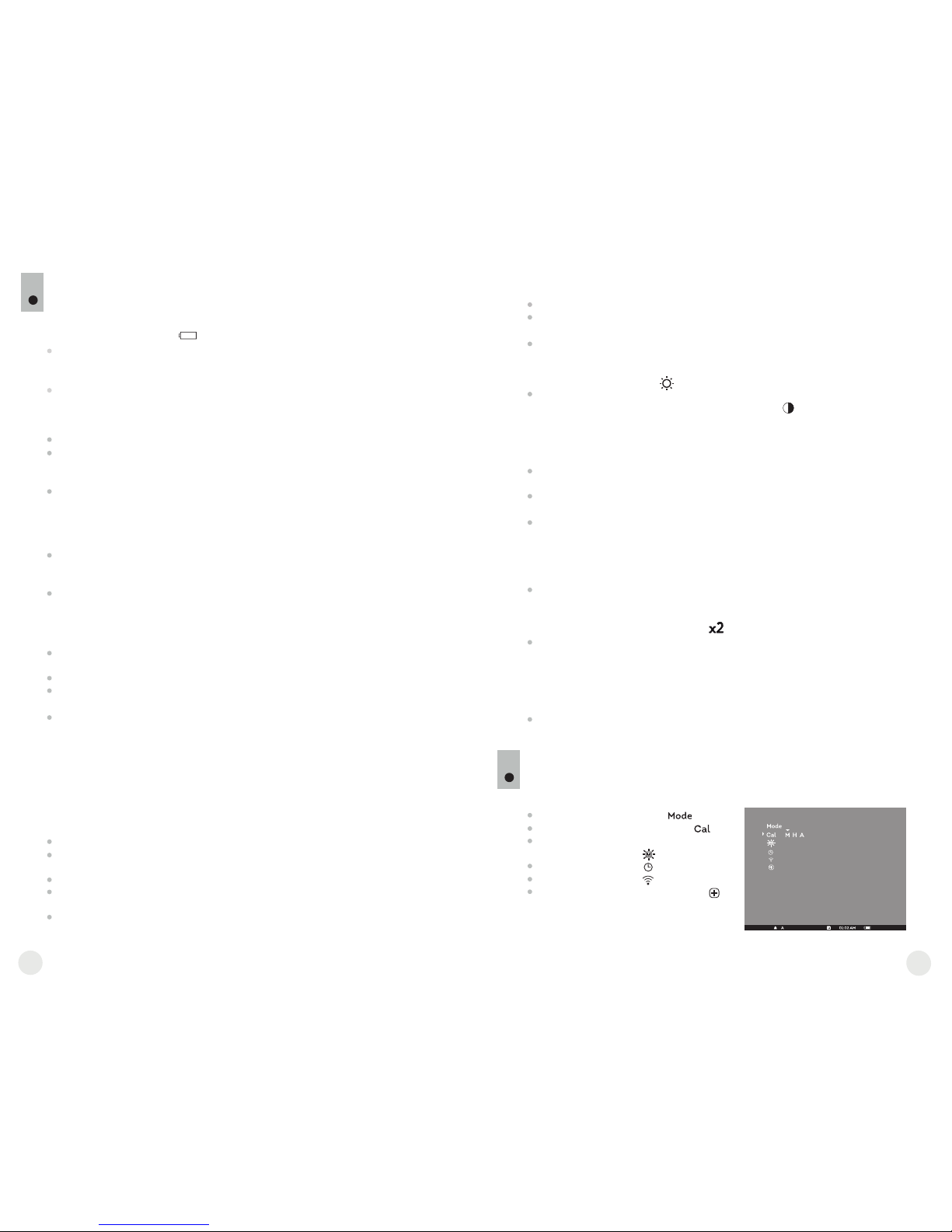
59
Примечание: время между калибровками зависит от нагрева сенсора.
При включении прибора калибровка может происходить чаще.
Откройте крышку объектива (1).
Настройте резкое изображение пиктограмм в строке статуса
вращением кольца диоптрийной настройки окуляра (4).
Для регулировки яркости дисплея кратко нажимайте кнопки навигации
“L EFT ” (10) (у меньш ени е) и “R IGHT” ( 11 ) (увелич ение) .
Соответствующая степень яркости (от 0 до 20) отобразится рядом с
пиктограммой яркости в правой верхней части дисплея.
Для перехода к регулировке контраста дисплея коротко нажмите
кнопку “MODE” (12) (появится пиктограмма ). Нажимайте кнопки
навигации “LEFT” (10) (уменьшение) и “RIGHT” (11) (увеличение) для
выбора степени контраста (от 0 до 20). Соответствующая степень
контраста отобразится рядом с пиктограммой контраста в правой
верхней части дисплея.
Выберите теплый неподвижный объект наблюдения, удаленный на
некотором расстоянии, например, 100 м.
Вращая кольцо фокусировки объектива (3), добейтесь наилучшего
качества изображения.
После данной настройки, независимо от дистанции и других условий,
вращать кольцо диоптрийной подстройки окуляра не требуется.
Настраивайте изображение только кольцом фокусировки объектива.
РАБОТА С ПРИБОРОМ. КАЛИБРОВКА.
9
Включите прибор нажатием кнопки “ON/OFF” (9). В случае разряда
батарей пиктограмма в строке статуса начнет мигать.
Откройте крышку (1) объектива.
Включите прибор кратким нажатием кнопки “ON/OFF” (9), нажмите и
удерживайте кнопку “MODE” (12) в течение двух секунд для входа в
меню.
Кнопками навигации “LEFT” (10) и “RIGHT” (11) выберите пункт Cal.
Кнопками навигации выберите режим “М”. Нажмите кнопку “MODE” для
подтверждения. Для выхода из меню нажмите и удерживайте кнопку
“MODE” в течение двух секунд или подождите 10 секунд для
автоматического выхода.
Закройте крышку объектива. Для калибровки кратко нажмите кнопку
“ON/OFF”. Изображение застынет на 1-2 секунды. Затем откройте
крышку объектива. Калибровка произведена.
В случае появления на дисплее артефактов (застывшего изображения,
вертикальных полос и т.п.) повторно произведите калибровку.
Включите прибор, откройте крышку объектива.
Нажмите и удерживайте кнопку “MODE” (12) в течение двух секунд для
входа в меню.
Кнопками навигации “LEFT” (10) и “RIGHT” (11) выберите пункт Cal.
Кнопками навигации выберите режим “H”. Нажмите кнопку “MODE” для
подтверждения.
Для калибровки кратко нажмите кнопку “ON/OFF”. Изображение
застынет на 1-2 секунды, и Вы услышите звук внутренней шторки.
Калибровка произведена.
При использовании автоматического режима прибор калибруется
са мо стоятель но с огла сно программн ом у алго ритму. Се нсор
закрывается внутренней шторкой автоматически. В данном режиме
допускается калибровка прибора пользователем с помощью кнопки
“ON/OFF”.
Включите прибор, откройте крышку объектива.
Нажмите и удерживайте кнопку “MODE” в течение двух секунд для
входа в меню.
Кнопками навигации “LEFT” (10) и “RIGHT” (11) выберите пункт Cal.
Кнопками навигации выберите режим “A”. Нажмите кнопку “MODE” для
подтверждения.
В момент автоматической калибровки изображение застынет на 1-2
секунды, и Вы услышите звук внутренней шторки.
Ручной (бесшумный) режим калибровки
Произведите калибровку изображения. Калибровка позволяет
выровнять температурный фон микроболометра и устранить
недостатки изображения.
Доступны три режима калибровки: ручной (M), полуавтоматический (H)
и автоматический (А).
Режим работы “Mode”
Выбор режима калибровки
Регулировка яркости
пиктограмм меню
Настройка часов
Авторизация ПДУ
Удаление дефектных пикселей
МЕНЮ
10
Функционал меню включает в себя следующие пункты:
82
81
Полуавтоматический режим калибровки
Автоматический режим калибровки
Дл я актив аци и ци фро во го з ум а 2x ( дос туп ен т ол ько при
использовании прибора в к ачестве монокуляра) нажмите и
удерживайте кнопку “RIGHT” (11) в течение двух секунд. В строке
статуса появится пиктограмма .
Для активации инверсии цвета изображения (функции “White hot” и
“Black hot”) нажмите и удерживайте кнопку “LEFT” (10) в течение
двух секунд. При использовании функции “White hot” (белый
горячий) теплые объекты отображаются более светлыми оттенками;
“Black hot” (черный горячий) - теплые объекты отображаются более
темными оттенками.
Для выключения прибора нажмите и удерживайте кнопку “ON/OFF”
(9) в течение двух секунд.
Дополнительные функции

Строка статуса
В строке статуса отображается следующая информация:
Режим работы (“Скалы”, ”Лес”, ”Распознавание”)
Режим калибровки (ручной, полуавтоматический, автоматический)
Включено увеличение x2 (“Zoom”)
Включена функция “Инверсия”
Текущее время
Текущий заряд батарей
Режимы работы
Имеется три автоматических режима работы тепловизора – “Скалы”
(высокий контраст), “Лес” (низкий контраст) и “Распознавание”
(улучшенная детализация).
Каждый из режимов включает в себя оптимальное сочетание
параметров (яркость, контраст, усиление сигнала и т.д.) для обеспечения
наилучшего качества изображения в конкретных условиях наблюдения.
Нажмите и удерживайте кнопку “MODE” (12) в течение двух секунд,
выберите режим кнопками навигации “LEFT” (10) и “RIGHT” (11).
Подтвердите выбор коротким нажатием кнопки “MODE”.
Пиктограмма выбранного режима отображается в строке статуса.
Выбор режима калибровки
См. раздел 8 “Эксплуатация”.
Нажмите и удерживайте кнопку “MODE” (12) в течение двух секунд для
входа в меню.
Кнопками навигации “LEFT” (10) и “RIGHT” (11) выберите
пиктограмму . Нажмите кнопку “MODE”.
Кнопками навигации выберите уровень яркости пиктограмм меню от
1 до 10.
Для выхода из меню нажмите и удерживайте кнопку “MODE” в течение
двух секунд или подождите 10 секунд для автоматического выхода.
Нажмите и удерживайте кнопку “MODE” (12) в течение двух секунд для
входа в меню.
Кнопками навигации “LEFT” (10) и “RIGHT” (11) выберите пиктограмму
. Нажмите кнопку “MODE”.
Кнопками навигации перемещайте курсор для выбора формата
времени “24” либо “AM/PM”.
Нажмите кнопку “MODE” для перехода к настройке значения часа.
Настройте кнопками навигации. Нажмите кнопку “MODE” для перехода
к настройке значения минут. Настройте кнопками навигации.
Для выхода из меню нажмите и удерживайте кнопку “MODE” в течение
двух секунд или подождите 10 секунд для автоматического выхода.
Авторизация пульта дистанционного управления
Беспроводной пульт дистанционного управления дублирует функции
включения прибора, инверсии изображения и калибровки.
На пульте имеется три кнопки:
Кнопка “ON” (22) - включение/выключение прибора
(включения – краткое нажатие/выключение –
долгое нажатие (2 сек)).
Кнопка (23) - инверсия изображения.
Кнопка “CAL” (24) – калибровка.
Перед началом работы с ПДУ его
необходимо активировать, для этого:
Включите прибор и выберите пункт
меню “Активация ПДУ” (пиктограмма ).
Нажмите кнопку “MODE” (12), появится сообщение “Wait” и начнется
обратный отсчет времени, в течение которого нажмите и удерживайте
в течение двух секунд любую кнопку ПДУ.
В случае успешной активации возле пиктограммы появится
сообщение “Complete”. Пульт активирован и готов к работе.
Если ПДУ не работает, замените батарею. Для этого открутите винты
на тыльной панели ПДУ, снимите заднюю крышку, извлеките старую и
вставьте новую батарею CR2032.
Удаление дефектных пикселей
Во время эксплуатации прибора на сенсоре возможно появление
дефектных (т.н. “битых”) пикселей, т.е. ярких либо темных точек с
постоянной яркостью, видимых на изображении. Приборы CORE
предоставляют возможность удалить дефектные пиксели на сенсоре
(микроболометре) программным способом.
Нажмите и удерживайте кнопку “MODE” (12) в течение двух секунд
для входа в меню.
Кнопк ами н авигации “LEFT” (10) и “ RIGHT” (11) выберите
пиктограмму и нажмите кнопку “MODE”.
В появившемся подменю выберите пиктограмму и нажмите кнопку
“MODE”.
84
83
Регулировка яркости пиктограмм
Настройка часов
В центре дисплея появится крест , на месте всплывающих иконок
появятся координаты (X;Y) креста относительно центра дисплея,
пиктограммы меню пропадут с дисплея.
Кнопками навигации перемещайте крест таким образом, чтобы
совместить центр креста с дефектным пикселем (дефектный
пиксель должен погаснуть). Кратковременное нажатие кнопки
“MODE” позволяет переключать направление движения креста с
горизонтального на вертикальное.
После совмещения центра креста с дефектным пикселем кратко
нажмите кнопку “ON/OFF” (9) для удаления дефектного пикселя.
В случае успешного выполнения удаления рядом с координатами
появится кратковременное сообщение “OK”.
Далее, перемещая крест, можно удалить следующий дефектный
пиксель. При перемещении креста-курсора в область вывода на
дисплей координат, последние перемещаются в правую нижнюю
часть дисплея.
Для выхода из пункта “Удаление дефектных пикселей” нажмите и
удерживайте кнопку “MODE” в течение двух секунд.
X=50
Y=50
24
23
22

Если Вы желаете вернуться к заводской “карте пикселей” (т.е. вернуть
все ранее удаленные дефектные пиксели в исходное состояние),
выберите в появившемся подменю пиктограмму и нажмите кнопку
“MODE” (12).
Справа от пиктограммы появятся пункты “Yes” и “No”.
Кнопками навигации выберите “Yes” и нажмите кнопку “MODE”.
Если Вы решили не возвращаться к заводской “карте пикселей”,
выберите “No” и нажмите кнопку “MODE”.
Для выхода из меню нажмите и удерживайте кнопку “MODE” в течение
двух секунд или подождите 10 секунд для автоматического выхода.
Внимание! На дисплее прибора допускается наличие 1-2 пикселей в
виде ярких белых или черных точек, которые не удаляются и
дефектом не являются.
УХОД И ХРАНЕНИЕ
11
Прибор имеет степень защиты IPX7 (защита от проникновения воды –
погружение в воду на глубину до 1 метра в течение 30 минут).
Самос тоятель но р е монтиро ва ть и р а збирать пр иб ор
запрещается!
Наружную чистку оптических деталей производите очень аккуратно и
только в случае необходимости. Вначале осторожно удалите (смахните
или сдуйте) с оптической поверх ности п ыль и п ес ок, после
осуществляйте чистк у. Пользуйтесь чистой хл опчатобумажной
салфеткой (ватой и деревянной палочкой), специальными средствами
для линз с многослойными покрытиями.
Храните прибор только в чехле, в сухом, хорошо вентилируемом
помещении. При длительном хранении извлеките батареи. Батареи не
должны подвергаться чрезмерному нагреву от солнечного света, огня
или подобных источников.
12
ВЫЯВЛЕНИЕ НЕИСПРАВНОСТЕЙ
В таблице приведен перечень проблем, которые могут возникнуть при
эксплуатации прибора. Произведите рекомендуемую проверку и
исправление в порядке, указанном в таблице. При наличии дефектов, не
перечисленных в таблице, или при невозможности самостоятельно
устранить дефект, прибор следует вернуть для ремонта.
неисправность
неисправность
возможная причина
возможная причина
исправление
исправление
Тепловизор
не включается.
Из обра жени е н ече тко е,
c вертикальными полосами
и неравномерным фоном.
Батареи установлены
неправильно.
Окислены контакты в контейнере
батарей или на крышке контейнера
батарей - "потекли" батареи
или на контакты попала
химически активная жидкость.
Батареи полностью разряжены
или одна из батарей вышла
из строя.
Необходима калибровка
изображение.
Установите батареи
в соответствии с маркировкой.
Очистите контакты внутри
контейнера батарей или на крышке
контейнера батарей.
Установите новые батареи.
Проведите калибровку изображения
согласно инструкциям раздела
8 “Эксплуатация”.
Изображение слишком
темное.
Установлен низкий уровень
яркости.
Отрегулируйте яркость кнопками
навигации.
Возврат к заводской “карте пикселей”.
86
85
Точка попадания не
совпадает с точкой
прицеливания.
Требуется калибровка дисплея. Произведите калибровку дисплея
в соответствии с инструкцией
(см. ниже).
Калибровка дисплея
Нажмите одновременно и удерживайте в течение двух секунд кнопки “LEFT” (10)
и “MODE” (12) либо кнопки (23) и (24) ПДУ для перехода в дополнительное меню.
Кнопками “LEFT” (10) или “RIGHT”(11) выберите пункт “Калибровка”
Нажмите “MODE” для подтверждения.
На дисплее появится вспомогательное перекрестие в ограничительной
рамке и символы .
Совместите пристрелочное перекрестие с центром метки прицела.
Для перемещения рамки с перекрестием по горизонтали используйте кнопки
“LEFT” или “RIGHT” (либо (22),(24) на ПДУ). Перемещение осуществляется как
при кратков ременном, так и при длительном нажатии на кнопки. Для
переключения направления движения с горизонтального на вертикальный
нажмите кнопку “MODE”.
Удерживайте кнопку “MODE” (или кнопку (23) ПДУ) нажатой в течение двух
секунд. Возле пиктограммы появится “2” и стрелки со значениями координат X и
Y
Удерживая метку прицела в точке прицеливания, переместите пристрелочное
перекрестие в точку попадания кнопками “LEFT” или “RIGHT” (или кнопками
(22);(24) ПДУ). Для переключения направления движения с горизонтального на
вертикальный нажмите кно пку “MODE” либо кнопку ( 23) ПДУ. Для
перемещения пристрелочного перекрестия по координатам X и Y нажимайте
кнопки “ LEFT” или “RIGHT” либ о кнопки ПДУ (22) и (24). Диапазон
перемещения пристрелочного креста относительно ограничительной рамки
по горизонтали и вертикали: +/-10.
В результате пристрелочное перекрестие должно совместиться с точкой
попадания, при этом метка прицела должна удерживаться в точке
прицеливания.
Для сохранения настроек пристрелки удерживайте кнопку “MODE” либо кнопку
(23) ПДУ в течение двух секунд - на дисплее появится сообщение “OK” и
произойдет выход из меню; изображение центра мишени совместится с центром
перекрестия дневного прицела.
Для возврата к заводским настройкам выберите “Yes” в пункте меню “Сброс к
заводским настройкам”. Сбрасываются следующие настройки:
Режим работы – “Лес”;
Режим калибровки – автоматический;
Яркость графики меню – 5;
Калибровка дисплея – координаты X=0, Y=0;
Увеличение – x1;
Инверсия – выключена;
Регулировка яркости – 10;
Регулировка контраста – 6.
Примечание. Доступ к дополнительному меню (пункты “Калибровка дисплея” и
“Сброс к заводским настройкам”) возможен только при использовании прибора в
режиме насадки.
2
X=-02
Y=06
1
Неплотно закрыта крышка
контейнера батарей.
Плотно закройте крышку
контейнера батарей.
 Loading...