

Page 1

Observatory base requirements
PAGE 2-4
Observatory installation guide
PAGE 5-10
Installing your protective rubber flooring
PAGE 11-12
Accessory bay installation guide
PAGE 13
Motor drive installation guide
PAGE 14-24
Additional notes
PAGE 25
Pulsar Observatories
OBSERVATORY INSTALLATION / USER GUIDES
CONTENTS:
FOR TECHNICAL SUPPORT CALL +44(0)1353 315006
Useful links:
http://www.pulsarobservatories.com/video-guides.php
http://www.pulsarobservatories.com/downloads.php
http://www.pulsarobservatories.com/driver-downloads.php
[Type text] Page 1
Page 2

OBSERVATORY BASE REQUIREMENTS
For best results your observatory should be bolted to a concrete hard standing. This can be prepared by
yourself or you can employ a local builder / tradesman to do the work for you.
We always recommend using one of our Rigel steel piers for mounting your
telescope. This will not only give you a rock solid permanent alignment for
your telescope mount, but also will allow you to dispense with the tripod,
which takes up valuable floor space, and prevents you from accidentally
kicking one of the legs!
Your concrete base will need a substantial central block of concrete to take
the weight of your telescope setup, to provide a really solid footing.
This block needs to be 1000mm x 1000mm square, with a minimum depth of
600mm, positioned in the centre of your base. This will allow ample
movement for offsetting the pier if required. In an ideal situation it can be
isolated from the surrounding floor, although this not entirely necessary for a
solid foundation.
The dimensions and specifications for concrete hard standing base are as follows:
2.2M OBSERVATORY – 2400mm square or circular.
2.7M OBSERVATORY – 3000mm square or circular.
The base is best raised above ground level by at least 50mm to assist drainage, and needs to be as flat and
level as possible to ensure good dome performance. Also, as stated above, it can be square or circular in
shape.
Obviously, the square base is easier to produce, using straight lengths of timber shuttering.
The overall depth of the base should be a minimum depth of 150mm.
[Type text] Page 2
Page 3
BUYING CONCRETE
Concrete is bought by metric volume. To calculate the required amount, simply multiply length in metres by width
in metres by depth in metres to calculate a volume in cubic metres. Ready mixed concrete companies usually
deliver in multiples of half-cubic metres, so "round-up" your calculated quantity accordingly. There is often an
excess haulage charge on part-loads, so check with the supplier.
The concrete should be reasonably wet to make handling and leveling as easy as possible. Use at least strength
C20 mixture (20N/mm² cured strength after 28 days) with a 50mm slump (a measure of 'sloppiness'). This is
roughly equivalent to the old 4:2:1 mix. The ready mixed concrete supplier will understand these references, and
the delivery wagon usually carries extra water that can be mixed into the concrete before pouring, if the mixture is
too stiff. However, bear in mind that adding further water to the prepared mix can affect the cured strength of the
finished concrete and may invalidate the strength guarantee of the supplier, leaving the contractor responsible for
any remedial work.
SOURCES
There are two sources of ready mixed concrete. Firstly, the national
concrete companies with local depots that deliver and discharge, these
companies will supply a given quantity of concrete of guaranteed
strength, and leave you to do the hard work. They will deliver any
quantity you require, from 1m³ upwards, in multiples of half cubic
metres. Many will offer free, technical advice - look in Yellow Pages for
local companies.
Note that ready-mixed concrete is sold by volume (m³) and not by weight. The concrete wagons usually carry
6m³, or sometimes 8m³, and you may be charged £15-£20 for each cubic metre not carried.
There are also 'mix and move' contractors, who mix the quantity of concrete you require on their specially
adapted wagons, and then barrow, or pump, the concrete to exactly where you require it. This concrete may
not meet the quality standards required of the larger national contractors, but it is usually adequate for
domestic use. Expect to pay more per m³ than the delivered ready-mix, but then, they are doing a lot of the
hard work for you! These contractors can also be found in Yellow Pages or the Thomson Local.
WORKING THE CONCRETE
A shovel or a strong rake is used to roughly level out the wet concrete,
and then a straight-edged timber can be used to tamp down the
concrete to the correct level. Tamping helps eliminate air pockets
being trapped in the body of the concrete and also helps to push the
hard aggregate into the concrete, bringing sufficient of the matrix to
the surface to make smoothing (floating) easier.
Tamper made from straight-edge timber
[Type text] Page 3
Page 4
FINISHING THE CONCRETE
A reasonably smooth surface can be obtained by repeatedly tamping wet concrete, but for a finer finish, the
surface should be smoothed using a steel float trowel. This is best done when the concrete has started to stiffen as
part of the hardening process, as the float trowel leaves fewer trowel marks. Hand floats, also known as Bull
Floats, are fine for small areas where a near-perfect finish is not essential.
Judging exactly when to commence floating, either with hand tools or with a power float, is an art in itself, and is
gauged from years of experience; too soon and the trowel marks will never disappear, too late and the concrete
might not 'rub-up' to a close finish.
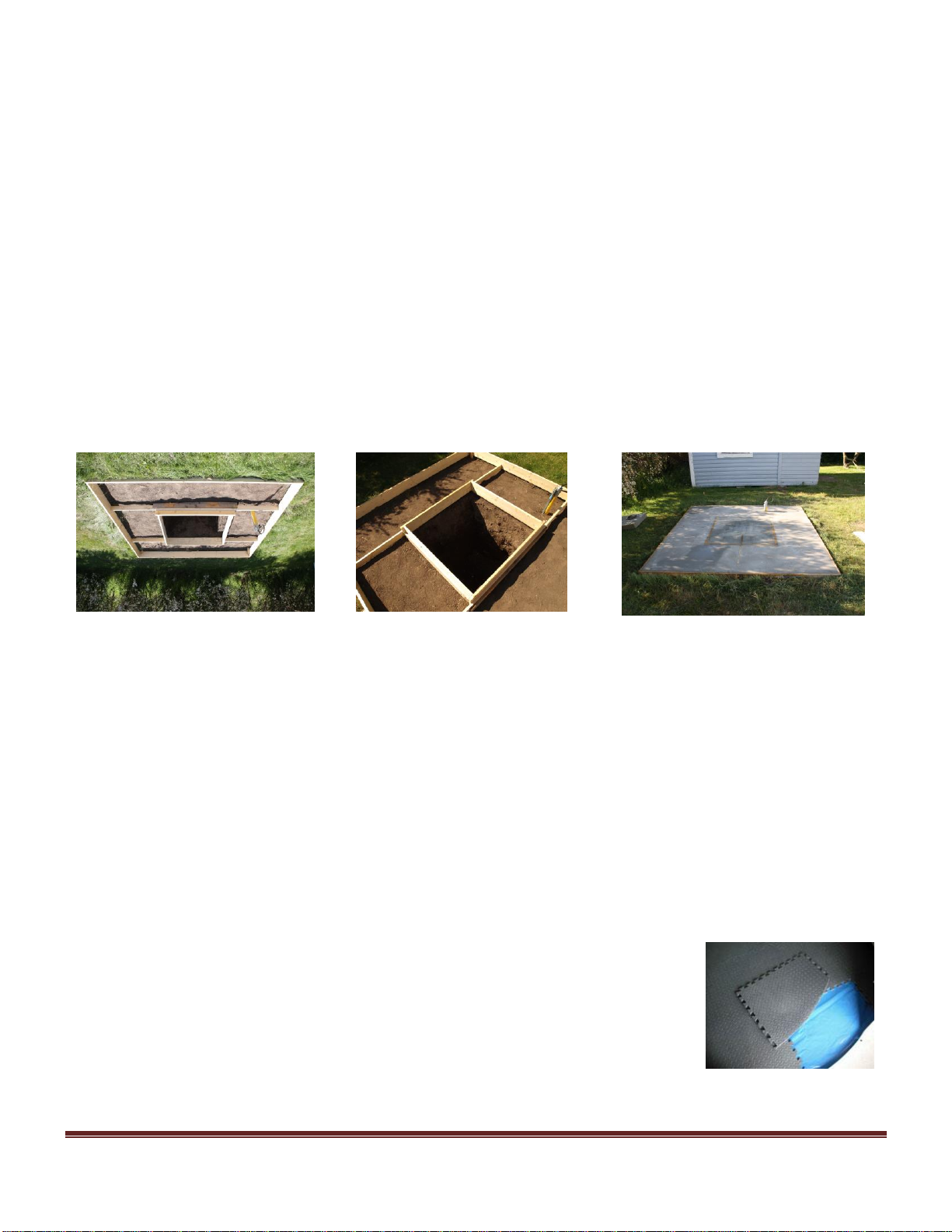
TIMBER SHUTTERING
The picture here shows an example of the timber shuttering in place, showing the hole for the pier block.
The shuttering should be checked for being square and level. In this example, ready mixed concrete was
poured into the pier hole first, and then levelled off, being pouring the remaining concrete into the base.
ELECTRICAL SUPPLY
If you wish to run power into the observatory, it may be an idea to run a conduit into the base to allow
cables to be pulled through. A simple calculation will give you the position where the conduit needs to lay in
the concrete (see above pictures). We recommend a power socket be mounted to the inside of the observatory
wall. This should be done a qualified electrician. Also, you may need to run additional cables for PC
networking, etc. Another conduit from the main feed to the pier area may also be useful.
ADDITIONAL NOTES
As an alternative, you can attach your observatory to a wooden decking base, but you will still require the
central concrete block to provide the stability for your telescope set up.
Your concrete base will be almost fully cured around a month after laying, however, after 1 week; the base
will be strong enough to allow observatory installation, and drilling to take place.
We recommend purchasing one of our high quality impact resistant interlocking
rubber tiled flooring systems. The tiles, in conjunction with the supplied plastic
membrane, provide a flooring surface that is not only waterproof, but also shock
resistant, protects falling eyepieces etc.! Also reduces noise and vibration, and
provides good insulation from the concrete.
[Type text] Page 4
Page 5

OBSERVATORY INSTALLATION / USER GUIDE
PREPARING THE BASE FOR A FULL HEIGHT INSTALLATION
Your base needs to be as flat and level as possible to ensure a good installation and smooth operation of the
dome.
It may be useful to mark the centre of your base and, using a compass, mark a North / South line through the
centre point. This will allow you to easily position your pier, which may need to be offset towards the South,
if you are using a wedge or German equatorial type mount. The pier should be installed after you have
secured the base wall sections.
PREPARING THE ROOF FOR A SHORT HEIGHT INSTALLATION
If you are installing a roof-mounted dome, place the assembled short wall, making sure that it is in the
correct position. Check the diameter of the wall assembly to ensure it is perfectly round, Mark the inside of
the dome track wall then proceed to cut the hole in your roof.
APERTURE LID ASSEMBLY
There are 4 PTFE guides to the aperture lid on the 2.2m dome and 6 PTFE guides to the aperture lid on the
2.7m dome, install using the M6x30mm countersink bolts, securing the guides with an M6 nut and washer on
the outside of the lid. There are no washers between the roller and lid on the 2.2m dome, but 3 washers
between each roller and lid on the 2.7m dome. Fit the latch brackets to the front of the dome lid using the M8
x 10mm button head bolts supplied. The holes may be pre-drilled, if not, the latch bracket fixing holes are
55mm from the front edge of the aperture lid and 178mm apart, see below. Never drill from inside as this
will damage the gel coat. The front of the aperture lid has the PTFE guides
closer to it.
[Type text] Page 5
Page 6
ASSEMBLY OF THE DOME TOP
Place the 2 rear dome sections onto a flat surface (preferably your observatory base), ready to be
assembled. Apply silicone sealant along the center of the flange of one dome quadrants and bolt together,
starting at the bottom bolt hole and working up to the top, ensuring that the panels are perfectly aligned on
the OUTSIDE of the dome, especially at the base where the wheels will be in contact. Any unevenness in
the seams will cause the observatory to bump over the wheels. File any edges down where necessary to
ensure the panels fit perfectly together. NOTE: It may be necessary to run an 8mm drill through some
holes that may not be perfectly aligned. Excess silicone sealant should be wiped off immediately with white
spirit or left to dry, and trimmed off with a sharp blade.
The aperture lid can be installed next by offering it up to the assembled dome sections and sliding the PTFE
guides into the grooves on the dome, carefully allow the aperture lid to sit in the fully open position on the
rear dome quadrants.
Now is a good time to fit the pulley assembly whilst the dome is at a convenient level.
Fit the pulley assembly to the very top hole on the back of the dome with the supplied 8mm x 25mm hexbolts
and nuts. Drill through and fit the second bolt provided with the pulley kit. Make sure that the wheel spins
freely, if not, file the flange as required.
Assemble the 2 remaining dome quadrants again paying attention to ensuring that the panels are perfectly
aligned on the OUTSIDE of the dome, especially at the base where the wheel will be in contact. File any
edges down where necessary to ensure the panels fit perfectly together.
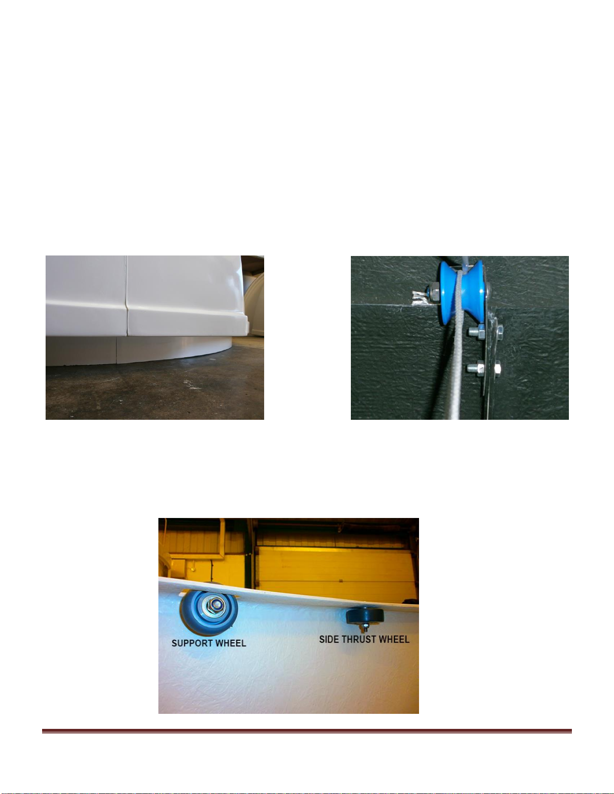
INSTALLING THE WALL PANEL WHEELS
There are 2 sets of wheels to be installed to the wall panels; 8 side thrust wheels and 8 support wheels as
shown here
[Type text] Page 6
Page 7

The holes are already drilled at 6mm to take the side thrust rollers. Place an M6 x 30mm button head bolt
through the hole in the top of the wall and secure the bolt underneath with a standard 6mm nut. Then, fit the
wheel and secure in place with a 6mm nyloc nut. DO NOT over tighten the nyloc and ensure that all wheels
turn freely. Complete this procedure for the remaining side thrust wheels.
Drill the 8mm holes for the support wheels as shown. Place an M8 x 40mm button head bolt through the hole
in the wall and secure the bolt with a standard 8mm nut, while fitting the wheel onto the bolt at the same
time. Then, secure the wheel in place with an 8mm nyloc nut. DO NOT over tighten the nyloc and ensure that
all wheels turn freely. Complete this procedure for the remaining support wheels.
ASSEMBLY OF WALL PANELS (FOR A FULL HEIGHT OBSERVATORY)
Place the wall panels on to the base. Apply A bead of silicone sealant to one surface only, down the length of
the flange, approximately15mm in from the outer edges, and bring the 2 panels together. Use M8 bolts and
washers supplied (1 either side), and bolt together the panels, starting with one at the top, then one at the
bottom, making sure that the outside wall surfaces are perfectly aligned. This is important to allow smooth
rotation of the dome top. NOTE: It may be necessary to run an 8mm drill through some holes that may not
be perfectly aligned. Insert and then immediately fix the remaining bolts. Wipe off excess sealant if
necessary, with white spirit. Complete the assembly of the wall panels.
Position the assembled wall section onto your concrete hard standing, making sure that you have aligned the
door opening to your preferred position. Also, to ensure the walls are perfectly circular, mark the diameter
of the observatory onto the base by finding the centre of the base and, using a timber batten, scribe a circle ;
2100mm diameter for the 2.2m observatory, 2600mm diameter for the 2.7m observatory.
Then bolt the base to the concrete using the supplied fixings. A silicone seal can be applied around the
outside of the base wall when the installation is complete provided the concrete is dry. Do not apply if wet or
damp, as the silicon will not adhere to the concrete.
FINAL ASSEMBLY
With assistance, lift the dome top into position on the base wall, ensuring that the structure is centered in
position over the base before lowering down.
Fit the rubber strip along the front opening edge of the hinged aperture lid. This will need to be cut to size
with a hacksaw to fit around the flange of the dome, and cut accurately to the correct length. Close the
aperture lid, and from the inside, position the 2 latches in place on the dome wall so that they are engaged
with the brackets, in the closed position. Carefully mark and drill the latch fixing holes and secure with the
supplied 5mm bolts.
[Type text] Page 7
Page 8

Thread the rope through the pulleys as displayed in the picture and attach each end of the rope to front and
rear of the sliding aperture lid, at the centre, as shown.
The holes may already be pre-drilled in the front and rear of the aperture lid, if not, follow the instruction
below:
With the sliding aperture lid fully open, mark the front hole 25mm from the edge, directly in line with the
center of the pulley wheel. Attach the rope as shown, using the M8 x 10mm button head bolt on the inside of
the lid, nut on the outside, placing the rope under the M8 flat washer, making sure that when tightened, the
rope is in line with the pulley. Mark the position for the rear rope fixing with the sliding lid fully closed. The
sliding lid will need to be fully open so that the hole can be drilled and rope attached from the back of the
dome. For the rear rope fixing, place the button head bolt again to the inside of the sliding lid, nut on the
outside.
The cleat is used to locate the rope when not being used to operate the pulley.
The cleat should be positioned at the lower part down the back wall, at a convenient height for you. Drill a
10mm hole close to the edge of the flange and fit the cleat, see picture below.
To give a pleasing finish to the observatory interior, use matt black aerosol paint and carefully spray over
the dome top joins and bolts, and any other interior marks.
[Type text] Page 8
Page 9
Attach the rubber sealing strip all around the underside edge of the dome top as shown above. It should be
positioned 5 mm in from the outside edge of the wall. This strip will act as a drip to prevent water from
running under the dome into the observatory, see picture above.
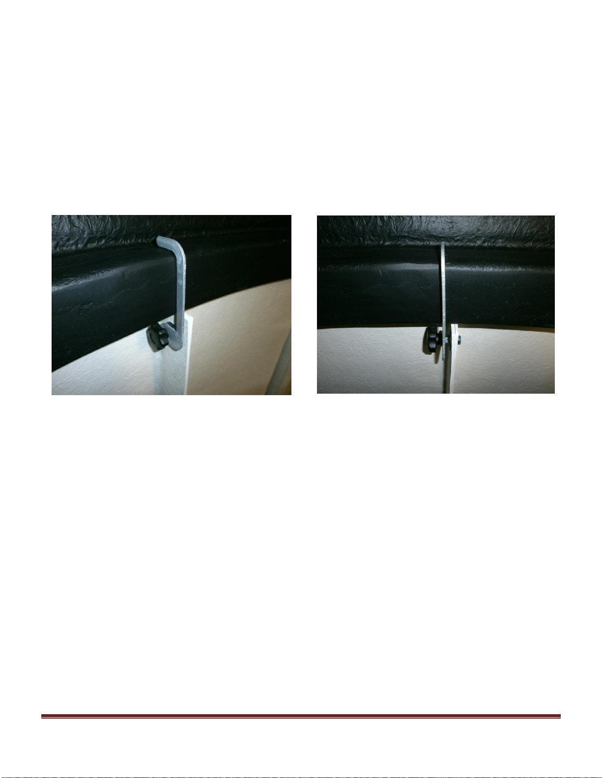
SECURITY CLAMPS
The observatory security clamps are not totally necessary in a secure garden but can provide added security for those
who require it. They also provide peace of mind when high winds occur, although we do not know of a case where a
dome top has been lifted off in high winds.
Position a clamp against the dome flange as shown in the picture, and mark the hole against the flange. Swing the
clamp in the full open position, against the dome wall and mark the hole against the flange again. Drill an 8mm hole
where the 2 marks cross. Insert the M8 hexbolt and secure with nut provided, then place the clamp on the bolt and
secure using the black scallop knob.
USING YOUR OBSERVATORY…
The door lock has an internal handle; do not leave keys in the outside door lock when inside the observatory.
Shutting the door on the inside could result in the key turning in the lock and locking the door!
The sliding aperture lid is easily opened and closed by pulling on the ropes. Hold the ropes with each hand
to control the lid, preventing it from crashing down with force.
Make sure that the clamps are swung up away from the wall before rotating the dome top at all times.
The observatory is easily rotated by hand to place the aperture in the correct position.
Always rotate the dome slowly to the next subject for safety reasons.
To give a pleasing finish to the observatory interior, use matt black aerosol paint and carefully spray over
the dome top joins and bolts, and any other interior marks. The only maintenance required for your
observatory is an occasional wash down of the exterior gel coat with a mild detergent.
Your observatory will give you many years of good service, treat it with respect and look after it!
[Type text] Page 9
Page 10

All domes can be used in conjunction with the ‘Dome Tracker’ for complete remote operation of your
observatory, see website for details: http://www.pulsar-observatories.com/
YOU ARE NOW READY TO INSTALL YOUR EQUIPMENT!
FOR TECHNICAL SUPPORT CALL +44(0)1366 315006
Visit us at www.pulsarobservatories.com or call 01366-315006
Installation of a Pulsar Observatory takes approximately 4 hours for 2 persons.
Extreme care should be taken when aligning the dome panels, as once they have been
joined with silicone sealant; it is very difficult to separate them. The door, with lock, is
pre-installed in the wall panel.
[Type text] Page 10
Page 11

OBSERVATORY FLOORING INSTALLATION GUIDE
NOTE: Your floor tiles will be wrapped inside your plastic membrane so do not cut or discard this!!
Thank you for purchasing protective flooring for your new observatory. Your observatory is watertight, and
should be sealed round its base with silicone sealant at the time of installation, or at the first opportunity the
base has dried out. However, you may experience condensation or under floor dampness owing to the nature
of your concrete base which will act like a sponge, absorbing water every time it rains. By laying a damp
proof membrane you can eliminate up to 85 - 90% of all moisture inside your dome. Fitting anti-fatigue
rubber flooring will further enhance the look of your observatory, providing additional insulation, and a
protective rubber surface which will help minimise damage to your equipment should you accidentally drop
something on the floor.
The plastic membrane is cut from 1000 gauge/250 micron waterproof polythene. The flooring, which comes
in 61cm x 61 cm interlocking rubber tiles, protects your floor, is shock absorbing, water resistant, and
reduces noise and vibration. It has a diamond plate finish.
TOOLS YOU WILL NEED
Your membrane, and flooring tiles are pre-cut to size, but you will need to trim both to fit around the flanges
of your observatory, and fit round your pier base. You will require a large pair of sharp scissors, such as
those used to cut wall paper, or a sharp Stanley knife to do this.
INSTALLING THE MEMBRANE
It is important to get the floor surface perfectly clean, preferably with a vacuum cleaner, before you lay any
floor covering. Any small stones will eventually wear holes in your floor covering. You may also wish to
seal the concrete base with a water resistant product such as Unibond.
Measure the position of the pier relative to the floor (your pier may be offset within the dome) and cut a
cross on the membrane to allow it to pass over the pier, then trim to fit. Please note that the rubber floor tiles
are NOT laid under the pier.
The membrane and the floor tiles are laid over the fibreglass flange on the inside of the observatory, within
10mm from the wall (the 10mm gap will allow for expansion of the rubber tiles in warmer weather). If the
flooring is fitted too tightly it may not lay flat in places.
[Type text] Page 11
Page 12

INSTALLING THE FLOOR TILES
It is advisable to lay your floor tiles out on a flat surface before installing them in your observatory. You
will find that the tiles have all been numbered on the reverse side, so lay the tiles face down and construct
your circle before fitting them inside the dome.
PLEASE NOTE: It is recommended that you
fit the outer tiles around the observatory wall
first, leaving the centre tiles until last. A
sharp pair of scissors will suit this task.
Make sure the tiles are not too tight a fit to
the inside edge, as already mentioned above,
or you will get a bulge in the middle.
Next fit the centre tiles one at a time ensuring
you get them in the correct number order.
Using a sharp Stanley knife and cut the tiles
to fit round the base of your pier. Also trim
the outside tiles to fit round any power
supplies or cables coming into the
observatory. Once you have fitted all the floor tiles ensure there are no bulges in the centre of the floor, and
gently tread down the tiles. You will find the edges and joints will fit better together once the floor has had
time to settle.
FOR TECHNICAL SUPPORT CALL +44(0) 01366 315006
[Type text] Page 12
Page 13

OBSERVATORY ACCESSORY BAY INSTALLATION
The accessory bay is easily installed in approx. 1 hour.
Tools required are a jigsaw with a diamond cutting blade, as used for cutting ceramic tile, 13mm spanner, socket key
set and applicator gun for applying the silicone sealant, electric drill with 8mm and 10mm drill bit.
Cover or remove telescope and equipment to protect from dust particles.
Mark the appropriate wall where the bay is to be installed using a felt tip pen on the inner edge of the wall profile as
shown in the image below.
Drill 4 10mm holes in the 4 corners to allow the jigsaw blade to make the cuts.
Cut out the glassfibre panel, the smooth the cut edges using a course glass paper on a wooden block.
This will also help to straighten an irregular cut.
Apply a bead of silicone sealant to the wall recess on the outside.
With assistance, position the bay to the wall and drill through the pre drilled holes in the bay and secure with the bolts
supplied, nuts to be on the inside of the observatory.
FOR TECHNICAL SUPPORT CALL +44(0) 1366 315006
[Type text] Page 13
Page 14

PULSAR OBSERVATORIES MOTOR DRIVE INSTALLATION
DOME ROTATION DRIVE INSTALLATION
The new style Rigel rotation drive unit allows you to control the dome rotation and shutter open / close using
either the LCD control unit or through a computer using the supplied software. The unit is powered from the
supplied 12 volt adaptor. The unit will need to be powered up, with the USB cable connected to a PC before
operation. The software will need to be installed on the PC and the observatory dome will require
calibration before using the drive unit for the first time.
The drive unit uses 3 drive motors driven by high torque 12V motors, powered by mains adaptor (supplied)
or battery pack.
INSTALLING THE DRIVE UNIT.
Install the rear drive motor unit to the dome wall first. Position the drive unit to the right side of one of the
wall flanges, as shown in diagram below, please note that the encoder is now installed to the motor unit, and
is spring loaded off the dome wall.
Position the drive unit up under the dome wall so that the encoder wheel is within 2 mm clearance from the
underside of the wall. Mark and carefully drill the 4 fixing holes, as shown below. It is advisable to drill a
small pilot hole from the inside first, then drill 8mm from the outside. This helps prevent the white gel coat
from breaking out. Bolt the drive unit in position using the M8x30mm bolts and washers provided, secure
with the standard M8 nuts supplied.
[Type text] Page 14
Page 15

FIXING THE ENCODER MAGNET.
Align the dome top to face the shutter towards the south (the recommended home position to allow the solar
panel to recharge the shutter battery), then mark and drill the position for the encoder magnet on the dome
flange, NOTE: the pickup sensor is to the right hand side of the encoder housing. Using a 10mm drill as
shown below. Push the magnet into the hole so that it is flush with the wall, and then cover the magnet with
the square adhesive pad.
Attach the wires from the control box onto the rear drive motors, taking care to ensure that the wires are
installed correctly to avoid damage to the motors, and to ensure that each motor rotates in the required
direction (both rear motors clockwise, front motor anti-clockwise; change wires over if necessary).
The number on each wire corresponds to a number below each motor terminal. This concludes the
installation.
USING THE ROTATION DRIVE
The 2 black knobs on the drive unit allow for adjusting the pressure against the drive rail. The top knob will
increase the pressure against the rail but the lower knob has to be slackened off first and must never be more
than lightly finger tight.
Switch on the power on the control unit.
The rotation drive can be operated with either the LCD onboard display menu or with the supplied software.
LCD display Software main screen
Operation using LCD display:
Before using the LCD display, the software will need to be installed as outlined below.
The observatory must be calibrated first, and the Home and Park position angle is entered in the software.
[Type text] Page 15
Page 16
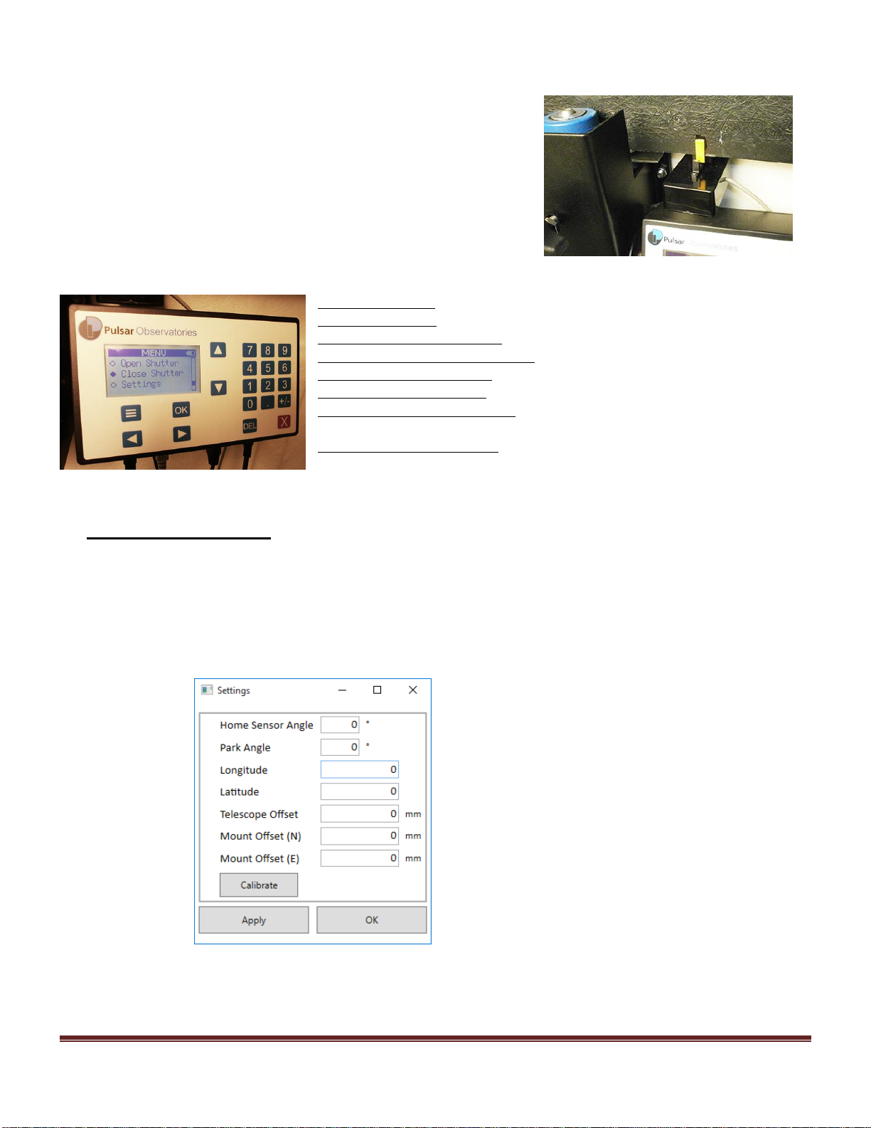
Home and Park can be the same angle reading, we recommend this angle to be 180 or due south, this will place the
solar charging panel south (facing midday Sun) and the shutter aperture in the correct position for observing.
Once the observatory shutter has been rotated to face south, install the
encoder position tag to the dome wall as shown, ensuring that it is below
the drive wheel and does not foul the wall flanges.
The LCD display is self-explanatory, the up / down arrows will scroll
through the menu, left / right arrows to slew dome left or right, the
number keypad is to set an angle to go to. The OK button will operate
each command.
OPEN SHUTTER: scroll through the menu to Open Shutter, press OK
CLOSE SHUTTER: scroll through the menu to Close Shutter, press OK
SLEW DOME CLOCKWISE: press right-hand arrow
SLEW DOME ANTI CLOCKWISE: press left-hand arrow
GO TO HOME POSITION: scroll through menu to Home, press OK
GO TO PARK POSITION: scroll through menu to Park, press OK
CHANGE SIDEREAL SPEED: scroll through menu to Sidereal, enter speed
on keypad, press OK
SEND DOME TO ANGLE: scroll through menu to Angle, enter angle on
keypad, press OK
Operation using software:
The CD provided will have the Pulsar remote dome software, along with an ASCOM driver for third party
software. Open the CD and follow the instructions, when complete, plug in the USB cable from the rotation
motor control box and connect the power supply. When using the software for the first time, go to the
settings icon and click ‘CALIBRATION’, this action will calibrate the observatory dome to allow accurate
alignment in the future. Once calibration is completed, the remote dome is ready for use.
Enter the Park and Home position angle (180 recommended).
[Type text] Page 16
Page 17
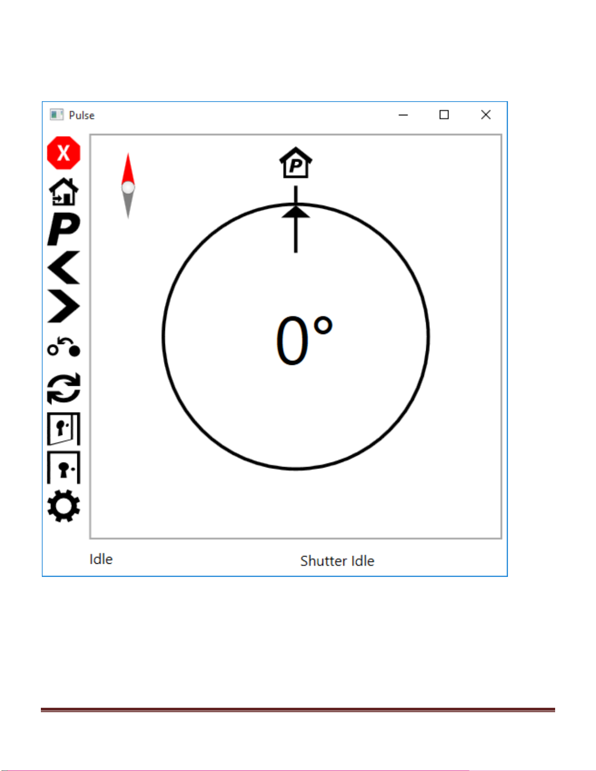
SOFTWARE CONTROLS
The diagram below shows screenshots with explanations for the related icons.
Main Screen
[Type text] Page 17
Page 18

Stop
Home
Park
Rotate Left
Rotate Right
[Type text] Page 18
Page 19
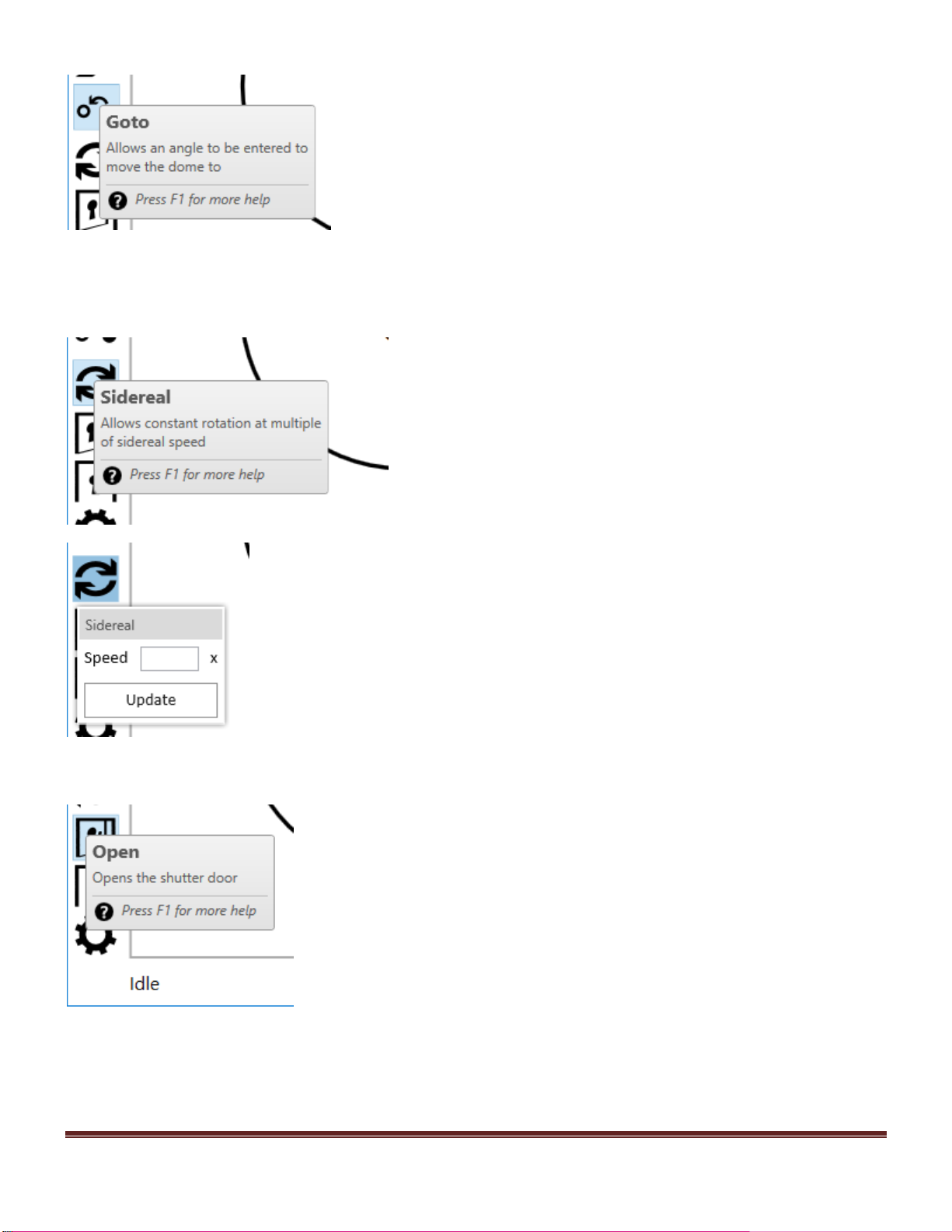
Goto
Sidereal
Open
[Type text] Page 19
Page 20

Close
Settings
Future planned features (available as software upgrade)
· RAC/DEC tracking
· Planet tracking
· Battery level and charging status of shutter
· Backlight timeout
PC connected to dome acts as a server so other PCs on the same network can use the same software.
iOS (will release before android) and Android app
USEFUL HINTS
If security clamps fitted to the observatory wall, PLEASE ENSURE THAT THEY ARE RELEASED BEFORE
ATTEMPTING TO ROTATE THE OBSERVATORY DOME.
FOR SAFETY REASONS IT IS ADVISABLE TO REPLACE THE SECURITY CLAMPS IF THE
DOME IS UNUSED FOR A LONG PERIOD OR HIGH WINDS ARE EXPECTED.
FOR TECHNICAL SUPPORT CALL +44(0)1366 315006
Or email: sales@pulsar-observatories.com
Visit us at www.pulsarobservatories.com
[Type text] Page 20
Page 21
SHUTTER DRIVE INSTALLATION / USER GUIDE
The new style Rigel shutter drive is powered by an in built lithium battery and is permanently powered on.
The battery is re-charged by the supplied solar panel. The red button on the front of the unit will open or
close the shutter; there is also a Bluetooth connection to the rotation unit to allow the shutter to be open or
closed from the rotation unit LCD display, or by using a PC and the supplied software.
PREPARING FOR THE INSTALL
It is advisable to install the chain brackets to the dome quadrants prior to installing the aperture lid, whilst
the dome top is partially assembled on the ground.
Also, the pulley system and latches will not need to be installed. Familiarize yourself with the different
components, and study the images to see how the shutter system operates.
INSTALLING THE CHAIN BRACKETS
It can be seen from the picture below that there are 3 side chain brackets on a 2.2m dome or 4 chain
brackets if on a 2.7m dome, and one top bracket to be installed on the right hand rear dome quadrant, as
viewed from the front. Position the brackets as shown, so that they are approximately equal distances apart
from each other, and also from the top bracket and drive unit position. The position of the chain brackets is
calculated by measuring the curvature of the shutter opening and spacing them equally apart.
Once the position of the chain brackets are marked, offer the brackets over the dome edge, if they are too
tight you will need to file the edge of the glassfibre where the bracket needs to fit. When the bracket neatly
slips over the dome edge, mark and drill the fixing holes for the chain brackets. Drill from the outside using
a 6mm drill bit. With the brackets in position, bolt the brackets in place, from the outside and through the top
roller, and secure with the 6mm nut supplied. Look at their alignment with each other, making sure that they
are perpendicular and in line with each other. This is easier if the chain is partly installed over the rollers.
Remove the lower bolt on the chain bracket and pack with washers if necessary, to achieve the desired
result. Position and mark the top bracket, paying attention to the position of the bracket as shown in the
picture, making sure that it lines up with the other brackets, this is important to ensure that the drive chain
moves smoothly. Also, make sure that the bracket is at the correct angle, by using additional washers as
packing. Again, drill the fixing holes with a 6mm drill bit and secure the bracket with the 6mm bolts
supplied. The hole nearest the outer edge will need to be drilled from outside, as it will not be accessible
from below.
[Type text] Page 21
Page 22
Rear bracket shown with shutter fully open
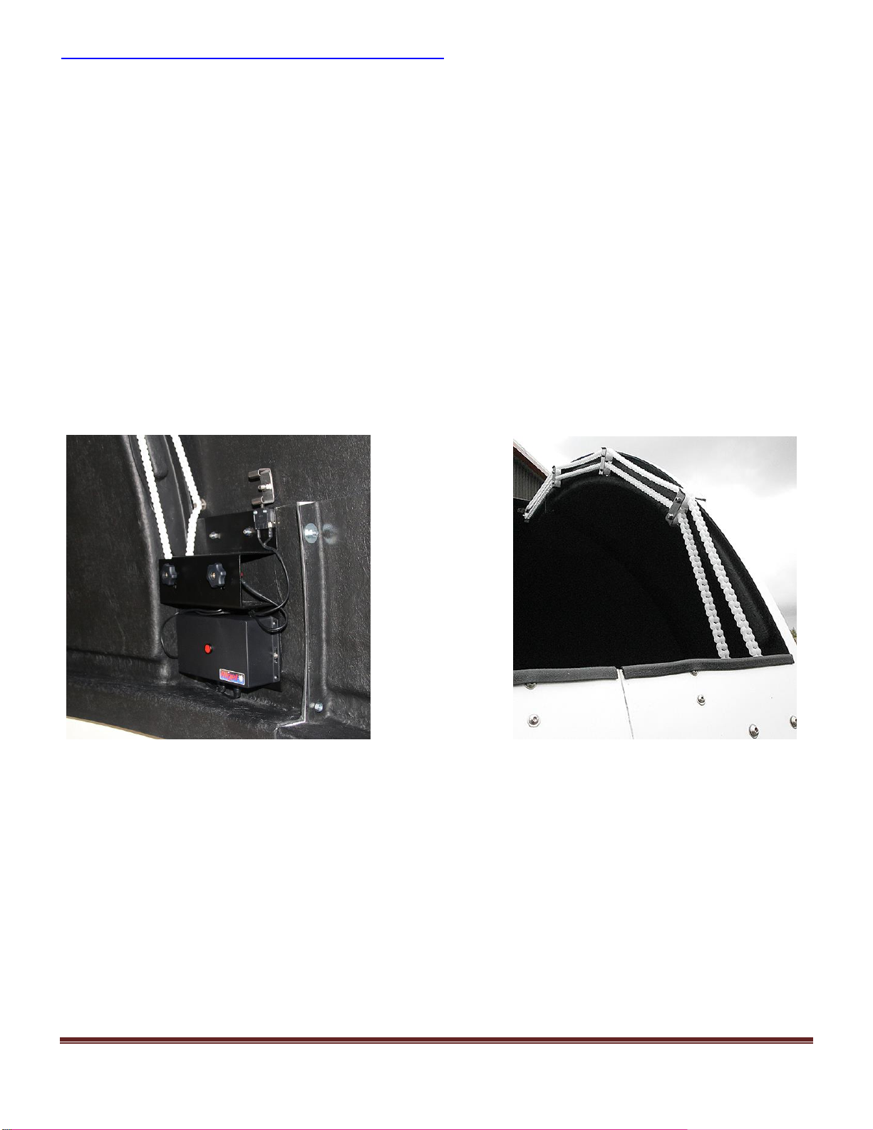
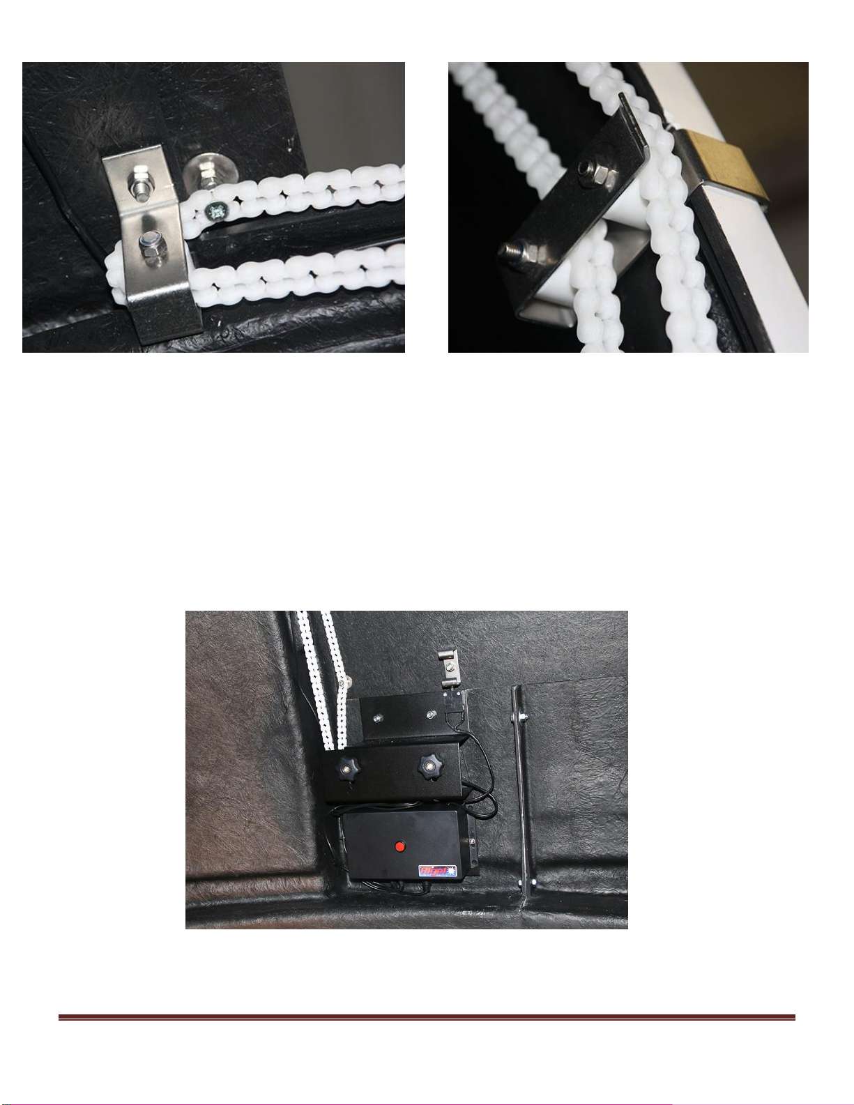
INSTALLING THE SHUTTER DRIVE UNIT
Install the chain through the rollers and rear bracket as shown in the pictures. Position the drive unit to the
dome wall as shown; level with the top of the aperture opening, ensuring that the drive sprocket is perfectly
in line with the chain, then mark the hole positions for attaching the drive casing. Drill a small pilot hole
first, then drill from the OUTSIDE using an 8mm drill. Fix the drive unit in position with the 8mm button
head bolts supplied. Connect up the chain but do not fix it to the shutter at this stage.
Take the chain around the motor sprocket and remove necessary links to keep the chain as tight as possible.
The links are easily snapped apart with a small flat screwdriver. An additional link may need to be removed
once the motor has been tested. The chain can be tensioned further by loosening the tensioning knobs and
pulling the motor down, please ensure that the sprocket remains square to the chain.
It is important that the chain is correctly in line through all the brackets, and with the drive sprocket, to
ensure smooth operation.
[Type text] Page 22
Page 23
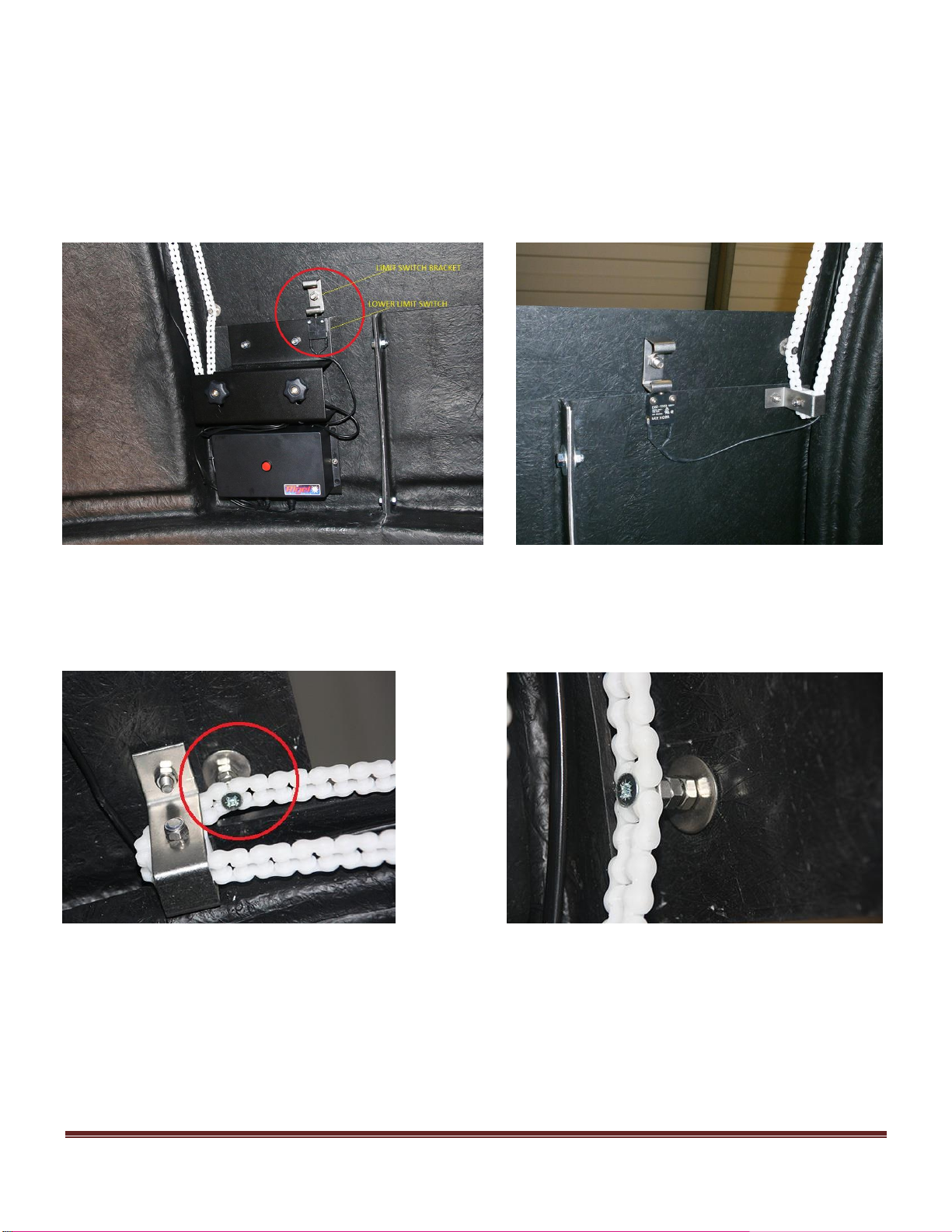
INSTALLING THE LIMIT SWITCHES
The limit switches are used to stop the shutter at the correct open and closed positions. You will need to use
the bracket supplied to operate the limit switches. It is important that the limit switches and bracket operate
correctly to prevent the shutter from over running. The lower limit switch is already installed to the shutter
motor unit, as shown in the picture. Position the bracket up to the lower limit switch so that it operates the
switch, then mark the hole position and fix the bracket using the bolt provided. Fully open the shutter and
install the upper limit switch, making sure that the switch is operated against the bracket before marking the
hole positions.
With the shutter closed, overlapping the front of the dome by approx. 25mm, position the chain against the
shutter, mark and drill the 6mm hole, and then attach the chain to the shutter with the 6mm bolt provided.
The chain is spaced away from the shutter using the 6mm nuts supplied, ensure that the shutter does not bind
on the brackets when opening and closing, by adding or removing a spacer nut (see picture below):
With the motor unit now in position, loosen the 2 black tensioning knobs on the motor casing and slide the
motor up to the top of the slots and re tighten the knobs. Run the cable to the top limit switch by feeding it
behind the chain brackets, and through a small hole that can be drilled to pass it through the dome flanges,
taking care that it cannot be in contact with the chain. Be careful to insure that the limit switches operate in
time to prevent the shutter from over running! After operating for the first time, the chain may need to be
shortened again by removing a link from one side, or adjusting the motor further. The chain can be
lubricated with a silicon spray; this will loosen the links and make operation smoother.
[Type text] Page 23
Page 24
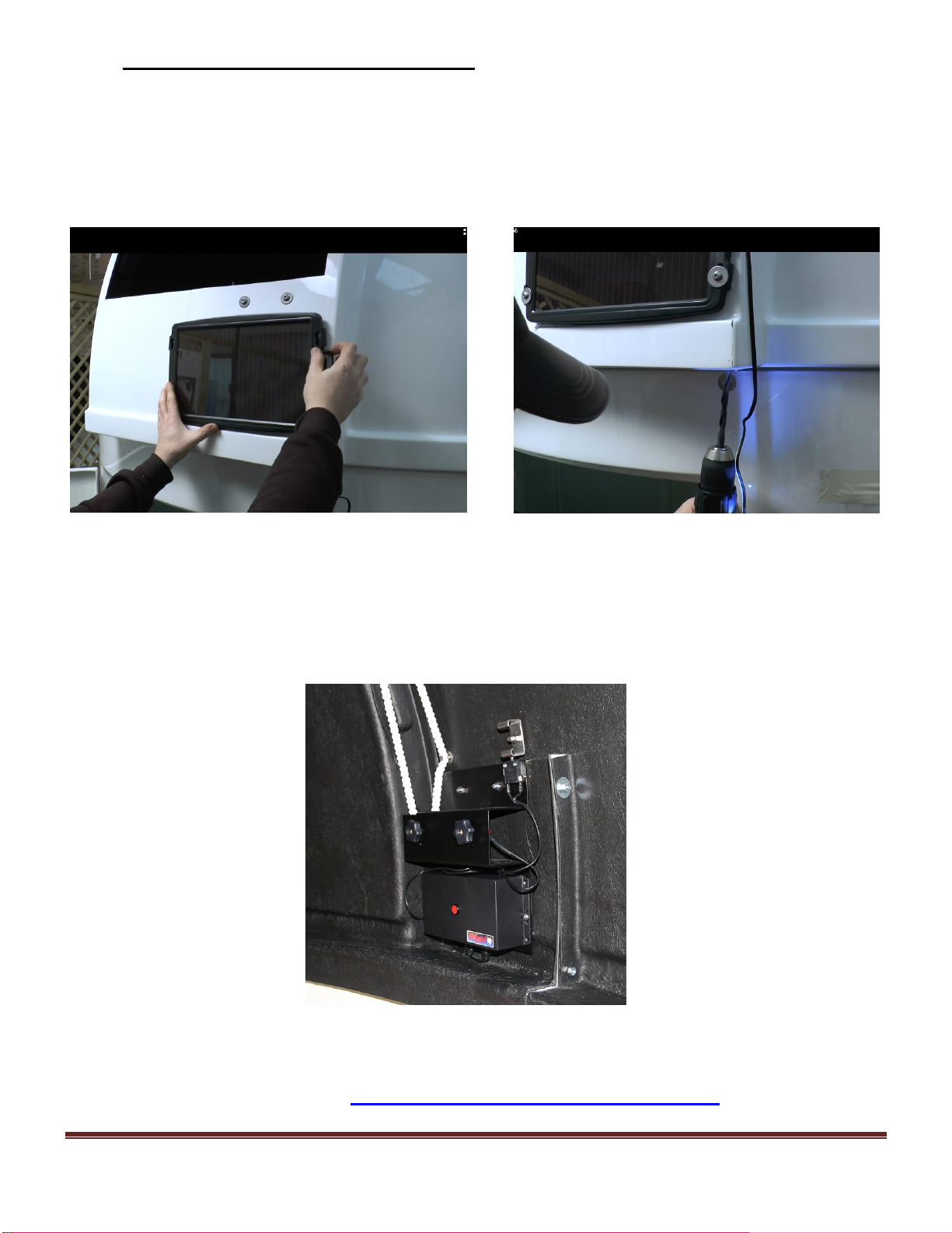
INSTALLATION OF SOLAR PANEL
The shutter drive unit is powered by the onboard lithium battery. This can be recharged using a power tank
battery charger or by the supplied solar panel accessory. (The solar panel may differ from the one shown in
the picture below).
Install the solar panel where shown on the picture below, using the bolts provided. Drill a hole under the rim
of the dome wall, pass the cable through, and then plug the adaptor into the 12v socket on the shutter control
unit.
OPERATING THE SHUTTER DRIVE MOTOR
The shutter drive unit is powered by a pre-installed lithium battery. The battery is recharged by the supplied
solar panel or by using a power tank battery charger. The shutter drive is permanently powered on and the
shutter can be opened or closed using the red button on the drive casing. Alternatively, the shutter can be
opened or closed using the LCD display on the rotation drive unit, via a Bluetooth connection with the
rotation drive, or remotely using the installed software on a computer.
FOR TECHNICAL SUPPORT CALL +44(0)1366 315006
Or email: sales@pulsar-observatories.com
[Type text] Page 24
Page 25

ADDITIONAL NOTES
VIDEO GUIDES
There are video installation guides available to view on our website; we strongly recommend viewing these
guides before attempting assembly of our observatory. Please follow the link below:
http://www.pulsarobservatories.com/video-guides.php more video guides will be added in due course.
If you are considering adding rotation or shutter drives to you observatory, to watch the video on dome
control, please follow the link below:
http://www.pulsarobservatories.com/video-guides.php
If security clamps fitted to the observatory wall, PLEASE ENSURE THAT THEY ARE RELEASED BEFORE
ATTEMPTING TO ROTATE THE OBSERVATORY DOME.
FOR SAFETY REASONS IT IS ADVISABLE TO REPLACE THE SECURITY CLAMPS IF THE
DOME IS UNUSED FOR A LONG PERIOD OR HIGH WINDS ARE EXPECTED.
Pulsar Observatories are market leaders in the supply of glassfibre observatories and we have invested
heavily over the years to ensure our products are of the highest quality. Our new unique, innovative remote
drive systems are by far the most technically advanced products, value for money.
We are constantly looking at new ways to improve our products and encourage suggestions and customer
feedback to help us stay ahead of the game. We also welcome pictures of your observatory setup to use in
our website gallery.
[Type text] Page 25
 Loading...