

Page 1

N
CHROMAFLOOD
CHROMABATTE
SPECIFICATION SPECIFICATION
CFLD100
CFLD200
CBAT100
CBAT200
CBAT300
The ChromaFlood and ChromaBatten contain state of the art, high
brightness, high efficiency Red, Green and Blue LEDs. These three
primary colours can be mixed together to make an incredible palette
of 16.7 million colours.
They are IP65 rated fixtures and therefore suitable for outdoor or
indoor use. They are powered directly from 100-240 Volts AC and
have full remote DMX control of RGB levels or can function in Stand
Alone Mode. Numerous chases and sequences are built in, enabling
superb lighting effects without complicated programming.
These impressive fixtures are ideal for the architectural and
entertainment markets to give an unlimited colour palette that can
enhance building facades, water features and focal displays or to
providing stunning dynamic colour in shows, conferences, concerts
and themed environments.
Like the ChromaBank, the ChromaFlood and ChromaBatten
contain a PULSAR ChromaZone controller and can therefore also
operate in 3, 6, 9, 10, 36, 42 or 46 Channel Modes.
It is useful to consider the ChromaFlood as being 1 of the 12
fixtures, and the ChromaBatten as being, either 1 or 3, of the 12
fixtures, within a ChromaBank.
Please see the Channel Assignments Tables sheet for details of
the different modes.
The ChromaFlood and ChromaBatten have numerous chases and
effects built in, making it possible to achieve fantastic effects without
programming. These internal effects can be selected via the User
Interface Module (UIM) on the rear of the units whilst in Stand Alone
mode, or from a controller using a digital PMX (Pulsar MultipleX) or
DMX (Digital MultipleX) signal.
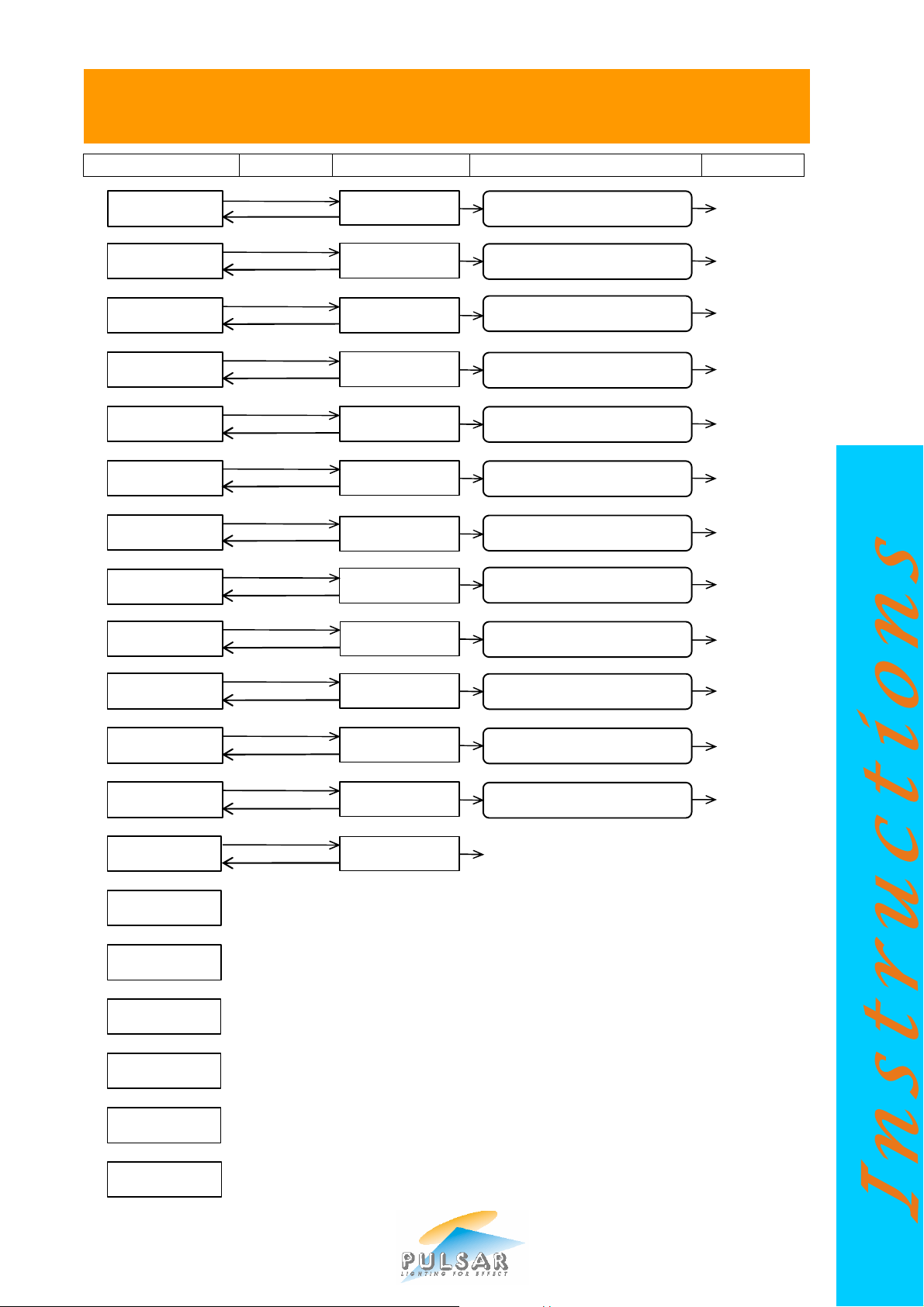
Please see the Menu Selection Overview sheet for a pictorial
representation of the menu functions.
The ChromaFlood and ChromaBatten have mounting brackets
making them ideal for floor, wall, ceiling or rig mounting.
The ChromaFlood picture at the top of this page shows the
mounting brackets arranged for floor mounting.
ChromaFlood and ChromaBatten have a colour code letter. This
signifies the finished colour of the fixture (B = Black, S = Silver). Other
colours may become available - please check with Pulsar if required.
The ChromaFlood and ChromaBatten have a thermal
management system. This progressively reduces the power to the
LEDs if the internal temperature exceeds limits set by the software.
-
ChromaFlood100 – 5,8,25,45,12x25,10x90
-
ChromaFlood200 – 8,25,45,12x25,10x90 lenses
-
ChromaBatten100 – 10, 25 and 45 degree lenses
-
ChromaBatten200 – 10, 25 and 45 degree lenses
-
ChromaBatten300 – 10, 25 and 45 degree lenses
lenses
Excess temperature will occur if the units are exposed to high
ambient temperatures or inadvertently covered. It is therefore
important for maximum performance that they have good ventilation
on all sides.
The lenses shipped with the ChromaFlood and ChromaBatten
may be easily changed. Currently 5 (ChromaFlood100 only), 8, 25,
45, 12x25 (elliptical) and 10x90 (elliptical) lens plates are available for
the ChromaFlood with 10, 25 and 45 degree lenses available for the
ChromaBatten.
Other lenses may become available, please contact Pulsar or see
www.pulsarlight.com
NB - Patents applied for
Mains Supply - The ChromaFlood and ChromaBatten work
correctly on any mains voltage from 100-240 VAC, 50-60Hz, (self
adjusting). Power consumption is 200 Watts max.
A 5m, bare ended, mains cable is provided. The bare end of the
cable should be fitted with a suitably approved and rated mains plug.
Note: in some countries it is a requirement that such a plug be fitted
by a qualified electrician.
WARNING - THIS APPLIANCE MUST BE EARTHED
For safety we recommend the use of a Residual Current Circuit
Breaker. An RCCB MUST be used when powering a
ChromaFlood or ChromaBatten in wet environments.
PMX/DMX In/Thru 5 Pin XLR Connectors
Digital Control Signals: Two 5 pin XLR connectors on 5m cables
(in/thru) are provided. The pin connections of the sockets are:
PMX (RS232/423) SIGNAL DMX SIGNAL
Pin 1 = Screen / Chassis Earth Pin 1 = Screen / Chassis Earth
Pin 2 = Signal (Blue) Pin 2 = Signal Pin 3 = Signal Earth (White) Pin 3 = Signal +
Pin 4 = no connection (Green) Pin 4 = no connection
Pin 5 = LVS (male only) (Red) Pin 5 = LVS (male only)
Wet / Damp Environment Use – these products are IP65
rated. However, the cable connections must also be
contained in a dry, low humidity, environment as water and
vapour will travel inside the cables from the connection joints into the
fixture. A waterproof connection box, or properly fitted IP68 rated
connectors, are essential for cable connections in such
environments. Suitable connectors are available from Pulsar.
Failure to take these precautions invalidates the guarantee.
for details
CONNECTIONS
CABLE COLOURS
Green/Yellow = Earth / Ground
Blue =
Live / Phase / Hot
Neutral
Brown =
Pulsar Light of Cambridge Limited ● 3 Coldhams Business Park ● Norman Way ● Cambridge ● CB1 3LH ● England ● Tel: 44 (0)1223 403500 ● Fax: 44 (0)1223 403501 ● Email: sales@pulsarlight.com ● Web: www.pulsarlight.com
Instructions
Page 2
U
SER INTERFACE MODULE A
N
D FUNCTIONS
LCD DISPLAY A 2 line, 16 character per line, LCD display is
DMX Address: n
used to set up, and indicate the status of, the ChromaFlood and
ChromaBatten.
At switch on, the display shows:
(where n=1 to 512)
Receiving:NO SIGNAL or DMX or PMX or ERROR
Press the ñ (Up) or ò (Down) keys to cycle through the Menu
Options (see LCD Display Sheet).
Press the X key on the UIM to change the settings.
Note: Program Mode self cancels after ~30 seconds if no keys have
been pressed.
Note: if, at any time, the display shows Receiving: ERROR, then
there is a problem with the DMX signal. It could be wiring,
termination or poorly implemented DMX.
? DMX Address – depending on the operating mode, a block
of 3, 6, 9, 10, 36, 42 or 46 channels is received from the DMX signal
– see Channel Assignments Tables. The DMX Address is the
number of the first channel in the block.
To set the required DMX Address, press the ñ or ò keys on the
UIM until the display shows DMX Address:
Press the X (change) key on the UIM, then set the start address
using the ñ or ò keys. These keys repeat if held down.
When the required DMX Address number shows in the display,
press the ü (Yes) key to save changes or X (Back) key to restore
the previous settings.
Note: the Receiving: text (NO SIGNAL / PMX / DMX / ERROR) in
the display is for information only.
? ChromaZone Mode - the unit can be run in similar modes
to the ChromaZone. The options are 3, 6, 9, 10, 36, 42 and 46
channel modes – see Channel Assignments Tables.
To set the required Mode, press the ñ or ò keys on the UIM until
the display shows ChromaZone Mode:
Press the X (change) key on the UIM, then select the required mode
using theñ or ò keys.
When the required ChromaZone Mode shows in the display, press
the ü (Yes) key to save changes or X (Back) key to restore the
previous settings.
? Channels per Fixture – the CFLD and CBAT can be run
in 3 channels per fixture or 6(CFLD) / 9(CBAT) channels per fixture
modes. The 6/9 channel modes allow a chase to be run across the
fixture. This is particularly effective in the CBAT where the Batten is
divided into 3 fixtures, each of RGB.
To set the required number of Channels per Fixture, press the ñ or
ò keys on the UIM until the display shows Channels per Fixture :
Press the X (change) key on the UIM, then select the required
number using the ñ or ò keys.
When the required number of Channels per Fixture shows in the
display, press the ü (Yes) key to save changes or X (Back) key to
restore the previous settings.
? Fixture number: the 36 RGB outputs from the built in
ChromaZone are divided into fixture groups. 36 divided by the
channels per fixture (set above) gives the number of fixtures available
from the data block.
For example, if you set the channels per fixture on a CBAT to 9, the
maximum number of fixtures available will be 4. See the Channel
Assignments Table for channel and fixture number colour details.
To set the required fixture number, press the ñ or ò keys on the
UIM until the display shows Fixture number:
Press the X (change) key on the UIM, then select the required
number using the ñ or ò keys.
When the required Fixture number shows in the display, press the
ü (Yes) key to save changes or X (Back) key to restore the previous
settings.
? Chase patterns: may be 6 or 12 way. E.g. two CBATs set
for 9 Channels per Fixture (3 x RGB) will run a 6 way chase.
To set the required chase patterns, press the ñ or ò keys on the
UIM until the display shows Chase patterns:
Press the X (change) key on the UIM, then select 6 or 12 way using
the ñ or ò keys.
When the required chase pattern way number shows in the
display, press the ü (Yes) key to save changes or X (Back) key to
restore the previous settings.
? Channel 10: may be set as a Grand Master for the 36 RGB
channels only, OR as a Global Grand Master for the 36 RGB
channels, the ALL Red ,Green and Blue, and the Chase Levels
To set the required Ch.10 mode of operation, press the ñ or ò keys
on the UIM until the display shows Ch.10…:
Press the X (change) key on the UIM, then select the required
number using the ñ or ò keys.
When the required Ch.10 operation shows in the display, press the
ü (Yes) key to save changes or X (Back) key to restore the previous
settings.
? Input Smoothing - ON or OFF. To disable the input
smoothing, e.g. for fast response to video graphics signals, set to
OFF
To turn the Input Smoothing ON/OFF, press the ñ or ò keys on
the UIM until the display shows Input Smoothing:
Press the X (change) key on the UIM, then select the required state
using theñ or ò keys.
When the required state shows in the display, press the ü (Yes) key
to save changes or X (Back) key to restore the previous settings.
? Low Voltage Supply - ON or OFF. To connect the LVS to
pin 5 of the MALE XLR, set to ON.
The LVS is used to power some PULSAR controllers, e.g. Outstation
OS1. 24V at up to 250mA d.c. is available.
To turn the Low Voltage Supply ON/OFF, press the ñ or ò keys
on the UIM until the display shows Low Voltage Supply is:
Press the X (change) key on the UIM, then select the required state
using theñ or ò keys.
When the required state shows in the display, press the ü (Yes) key
to save changes or X (Back) key to restore the previous settings.
? DMX Line Termination – ON or OFF, set the last unit in
the DMX cable run to ON, all others to OFF. Errors can often occur if
the DMX line is not terminated. DMX errors are shown in the display
as:
DMX Address: n
Receiving: ERROR
To turn the DMX Line Termination ON/OFF, press the ñ or ò keys
on the UIM until the display shows DMX Line Termination:
Press the X (change) key on the UIM, then select the required state
using the ñ or ò keys.
When the required state shows in the display, press the ü (Yes) key
to save changes or X (Back) key to restore the previous settings.
? If NoSignal use: In the event the CFLD or CBAT is not
receiving a DMX signal (e.g. controller no longer present), the unit
may either use the user-programmable Stand Alone Settings (see
Stand Alone Settings View/Change below) OR continue to use the
Last DMX Packet received.
To select the If NoSignal use: requirement, press the ñ or ò keys
on the UIM until the display shows If NoSignal use
Press the X (change) key on the UIM, then select the requirement
using the ñ or ò keys.
When your requirement is showing in the display, press the ü (Yes)
key to save changes or X (Back) key to restore the previous settings.
? Stand Alone Settings View/Change
There are three possibilities depending on:
a) whether there is an input signal and
b) whether "If NoSignal use:" is set to "Stand Alone Mode" or set to
"Last DMX Packet".
1. No Signal + Use Stand Alone Mode:
The current Stand Alone Settings may be viewed, changed and
saved as the new Stand Alone Settings.
2. No Signal + Use Last DMX Packet:
The channel levels of the Last DMX Packet (if any) may be viewed,
changed and saved as the new Stand Alone Settings.
3. Signal present:
The incoming signal overwrites any changes made but these
incoming channel levels may be set at the controller, viewed and
saved as the new Stand Alone Settings.
Page 3
USER INTERFACE MODULE A
N
D FUNCTIONS
OTHER INFORMATION
CHROMAFLOOD
CHROMABATTEN
Stand Alone Settings View/Change (continued)
To View/Change the Stand Alone Settings, press the ñ or ò keys
on the UIM until the display shows Stand Alone Settings
View/Change.
Press the X (change) key on the UIM, then select the channel to
view/change using the ï or ð keys. These keys repeat if held
down. When the channel to be viewed/changed is showing in the
display, press the ñ or ò keys to change the value. These keys
repeat if held down. The display shows both the bit number (0-255)
and percentage (0-100%).
Please see the Chase Select Table when modifying chases.
To modify further channels, select the channel to view/change using
the ï or ð repeat keys, pressing the ñ or ò repeat keys to
change the value.
When you have finished modifying channels, press the ü (Yes) key
to save changes or X (Back) key to restore the previous settings.
? VIEW(Sig)/SET(NoSig) Chan Levels
To View the Channel Levels/Change the Stand Alone Settings, press
the ñ or ò keys on the UIM until the display shows
VIEW(Sig)/SET(NoSig) Chan Levels
Press the X (change) key on the UIM, then select the channel to
change/view using the ï or ð keys. These keys repeat if held
down.
When the channel to be changed/viewed is showing in the display,
press the ñ or ò keys to change the value. These keys repeat if
held down. The display shows both percentage (0-100%) and bit
number (0-255), and for channels 4 (Chase 1 Select) and 7 (Chase 2
Select) the chases selected.
Please see the Chase Select Table when modifying chases.
Notes:
• this menu item is for this session use only, data is never saved.
• the values can only be changed if the unit is not receiving data.
• pressing the X or ü keys returns to the main menu.
? Restore Factory Default Settings
To restore the factory default settings, press the ñ or ò keys on the
UIM until the display shows Restore Factory Default Settings.
Press the X (change) key on the UIM, then press the ü (Yes) key to
restore defaults or X (Back) key to exit.
The factory default settings are
DMX Address 1
ChromaZone Mode 46 Channel
Channels per Fixture 3 (CFLD) / 9(CBAT)
Fixture number 1
Chase patterns 12 Way
Channel 10 Grand Master for the 36 RGBs only
Input Smoothing ON
Low Voltage Supply ON
DMX Line Termination OFF
If NoSignal use: Stand Alone Mode
Stand Alone Settings Ch.1 – 3 = 0 bits / 0%
Ch.4 = Chase 1 Select = Auto Chase
Ch.5 = Chase 1 Speed = 128 bits / 50%
Ch.6 = Chase 1 Level = 255 bits / 100%
Ch.7 – 46 = 0 bits / 0%
Failure of the internal ChromaFlood or ChromaBatten 5 Amp,
5x20mm Power Supply Fuse, usually indicates an internal fault
requiring servicing by a qualified engineer.
If the front glass becomes cracked or broken, disconnect from the
mains immediately and have the unit repaired. Replacement glasses
are available from Pulsar.
The PMX/DMX connections (input and thru) are protected against
inadvertent shorts to 240Vac and static damage.
PORTABLE APPLIANCE TESTING - The Pulsar
ChromaFlood and ChromaBatten may be safely Earth Bond and
Insulation Tested.
STANDARDS - The Pulsar ChromaFlood and ChromaBatten
comply with the following International and National Standards:
Electrical Safety - IEC65, EN60065, BS415
EMC - EN50081-1, EN55022, EN50082-1
Index of Protection – IP65
Marking Directive 93/68/EEC - The Pulsar
ChromaFlood and ChromaBatten both meet the
EMC Directive 89/336/EEC and the Low Voltage
Directive 73/23/EEC.
Conforms to: ANSI/UL Standard 6500
Certified to: CAN/CSA-E60065-00
GUARANTEE - 12 months from the date of original purchase. The
guarantee is limited to parts and labour. The guarantee is void if the
unit is misused, the cable connections are not in a dry environment or
made using an IP68 rated connector, or unauthorised persons
perform repairs. In the unlikely event of a fault occurring, do not use
without repair. Return the unit to your supplier with a description of
the fault, or direct to Pulsar for immediate attention
DIMENSIONS AND WEIGHTS
Code Unit Width Height Depth Weight
mm mm mm kg
CFLD200
CBAT200 ChromaBatten200 1198.0 132.0 132.0 12.4
Pulsar Light of Cambridge Limited ? 3 Coldhams Business Park ? Norman Way ? Cambridge ? CB1 3LH ? England ? Tel: 44 (0)1223 403500 ? Fax: 44 (0)1223 403501 ? Email: sales@pulsarlight.com ? Web: www.pulsarlight.com
ChromaFlood200
365.0 373.0 118.0 8.0
Page 4
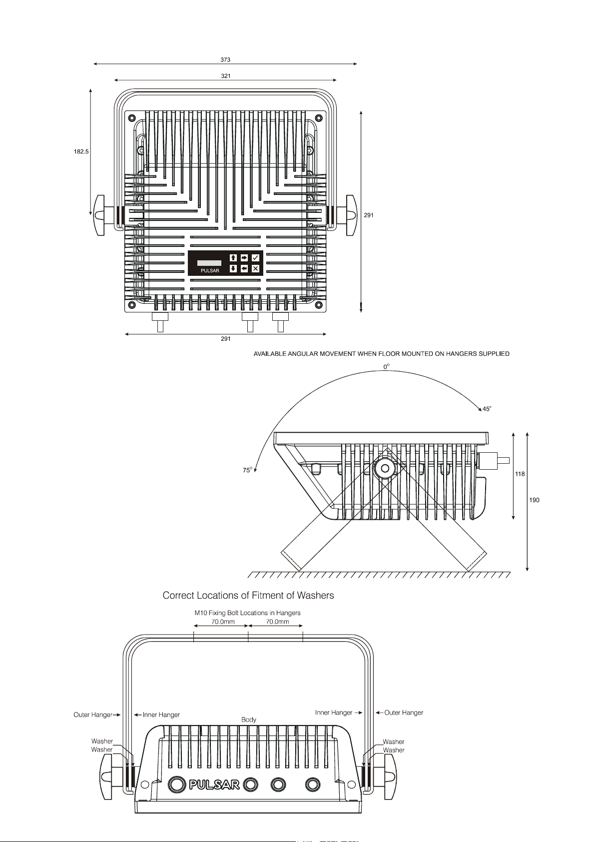
ChromaFlood100 and ChromaFlood200 Mechanical Details
Page 5
36 Channel Mode
3 Ch
annels
/ Fixture
6 Channels
/ Fixture
9 Channels
/ Fixture
42 Channel Mode
3 Channels /
Fixture
6 Channels
/ Fixture
9 Ch
annels
/ Fixture
46 Channel Mode
3 Ch
annels
/ Fixture
6 Channels
/ Fixture
9 Channels
/ Fixture
3
Channel Mode
6 Channel Mode
9
Channel Mod
e
10 Channel Mod
e
CHROMAFLOOD AND CHROMABATTEN
CHANNEL ASSIGNMENTS TABLES
1 All Red
2 All Green
3 All Blue
1 All Red
2 All Green
3 All Blue
4 Chase1 Select (see Chase Table)
5 Chase1 Speed
6 Chase1 Level
7 Chase2 Select (see Chase Table)
8 Chase2 Speed
9 Chase2 Level
1 Fixture 1 Red 1 Fixture 1 Red 1 1 Fixture 1 Red 1
2 Fixture 1 Green 2 Fixture 1 Green 1 2 Fixture 1 Green 1
3 Fixture 1 Blue 3 Fixture 1 Blue 1 3 Fixture 1 Blue 1
4 Fixture 2 Red 4 Fixture 1 Red 2 4 Fixture 1 Red 2
5 Fixture 2 Green 5 Fixture 1 Green 2 5 Fixture 1 Green 2
6 Fixture 2 Blue 6 Fixture 1 Blue 2 6 Fixture 1 Blue 2
36 Fixture 12 Blue 36 Fixture 6 Blue 2 36 Fixture 4 Blue 3
1 All Red
2 All Green
3 All Blue
4 Chase Select (see Chase Table)
5 Chase Speed
6 Chase Level
1 All Red
2 All Green
3 All Blue
4 Chase1 Select (see Chase Table)
5 Chase1 Speed
6 Chase1 Level
7 Chase2 Select (see Chase Table)
8 Chase2 Speed
9 Chase2 Level
10 Global Grand Master
1-6 as 6 Channel Mode 1-6 as 6 Channel Mode 1-6 as 6 Channel Mode
7 Fixture 1 Red 7 Fixture 1 Red 1 7 Fixture 1 Red 1
8 Fixture 1 Green 8 Fixture 1 Green 1 8 Fixture 1 Green1
9 Fixture 1 Blue 9 Fixture 1 Blue 1 9 Fixture 1 Blue 1
10 Fixture 2 Red 10 Fixture 1 Red 2 10 Fixture 1 Red 2
11 Fixture 2 Green 11 Fixture 1 Green 2 11 Fixture 1 Green 2
12 Fixture 2 Blue 12 Fixture 1 Blue 2 12 Fixture 1 Blue 2
42 Fixture 12 Blue 42 Fixture 6 Blue 2 42 Fixture 4 Blue 3
1-9 as 9 Channel Mode 1-9 as 9 Channel Mode 1-9 as 9 Channel Mode
10 36xRGBGrand Master 10 36xRGB Grand Master 10 36xRGB Grand Master
OR OR OR
10 Global Grand Master 10 Global Grand Master 10 Global Grand Master
11 Fixture 1 Red 11 Fixture 1 Red 1 11 Fixture 1 Red 1
12 Fixture 1 Green 12 Fixture 1 Green 1 12 Fixture 1 Green 1
13 Fixture 1 Blue 13 Fixture 1 Blue 1 13 Fixture 1 Blue 1
14 Fixture 2 Red 14 Fixture 2 Red 2 14 Fixture 1 Red 2
15 Fixture 2 Green 15 Fixture 2 Green 2 15 Fixture 1 Green 2
16 Fixture 2 Blue 16 Fixture 2 Blue 2 16 Fixture 1 Blue 2
46 Fixture 12 Blue 46 Fixture 6 Blue 2 46 Fixture 4 Blue 3
Pulsar Light of Cambridge Limited ? 3 Coldhams Business Park ? Norman Way ? Cambridge ? CB1 3LH ? England ? Tel: 44 (0)1223 403500 ? Fax: 44 (0)1223 403501 ? Email: sales@pulsarlight.com ? Web: www.pulsarlight.com
Page 6

ChromaZone
All 3 at 100%
=
Auto Colour Change
Pulsar ChromaZone / ChromaBank / ChromaFlood / ChromaBatten Software Version No. 4.0 (MAIN micro 4.0
09-09-05 or later + UIM micro 1.0 07-03-05 or later ) has many exciting features.• Two built in Chases – allowing
superimposition of effects and crossfading between chases. Chase 1 and 2 use the same table of 31 chases but
there are differences to give you more choice - Chase 1 uses the ALL Red, Green and Blue Channels, 1, 2 & 3, to
change the colour of some chases (see table) while Chase 2 stays white and uses them to give a background colour.
The chases have a very wide range of speeds.
• 7 operating modes: 3, 6, 9, 10, 36, 42 and 46 Channel Modes.
• A Master Dimmer Channel (Ch.10) for the 36 individual RGB channels, which may become a Global Grand Master
for the All R/G/B and Chases Levels too.
• Input Smoothing may be disabled for fast display of video graphics and video frame rate capability.
• Please see the Channel Assignments Table page for details of the Operating Modes and how to select them,
Channel Listings, and further information.
Chase % Bit Chase Notes
No. Input No. Description
15 100 255 Auto Chase
95 244 Green Yellow Red Bar Graph Reverse Use Channel1
92 236 Green Yellow Red Bar Graph Forward Use Channel1
14 89 228 Rainbow Strobe
13 86 220 White / Any Colour Strobe Channels 1, 2 & 3 set colour
83 212 White / Any Colour Crossover Channels 1, 2 & 3 set colour
Software Version 4.0
TM
12 80 204 Blue-Yellow Wave Reverse
77 196 Blue-Yellow Wave Forward
73 188 Green-Magenta Wave Reverse
11 70 180 Green-Magenta Wave Forward
67 172 Red-Cyan / AnyCol/Op.Col Wave Forward
10 64 164 Red-Cyan / AnyCol/Op.Col Wave Reverse
9 61 156 Black-White/AnyColour Wave Forward
58 148 Black-White/AnyColour Wave Reverse
8 55 140 Random Cols. Chase1 Crossfade, Chase2 Snap
52 132 Rainbow 2 Crossfade Forward
48 124 Rainbow 2 Crossfade Reverse
7 45 116 Rainbow Crossfade Forward
6 42 108 Rainbow Crossfade Reverse
39 100 “Follow 3” 18 Contrasting Colours Reverse
5 36 92 “Follow 3” 18 Contrasting Colours Forward
33 84 18 Crossfading Colours Reverse
4 30 76 18 Crossfading Colours Forward
27 68 White/AnyColour/AutoColour Cascade Reverse
23 60 White/AnyColour/AutoColour Cascade Forward
Channels 1, 2 & 3 set colour
All 3 at 0% = Red-Cyan
Channels 1, 2 & 3 set colour
All 3 at 0% = White.
Wider primary colours to
compensate for extra diffusion
Equal width primary &
secondary colours
Channels 1, 2 & 3 set colour.
All 3 at 0% = White.
3 20 52 6 Crossfading Pastel Colours
17 44 Colour Wipes
2 14 36 6 Crossfading Colours
1 11 28 6 Separate Colours
8 20 Red Green Blue Bar Graphs Reverse Use Channels 1, 2 & 3
5 12 Red Green Blue Bar Graphs Forward Use Channels 1, 2 & 3
0 0 0 No Chase
Page 7
Display
Operation
Display
Choices
Operation
t
N.n
N.n
Ch.10
X
3
6
(FLOOD)/9(BAT
TEN)
1-12 of
12
1-6
of 6(FLD)/1
-
4 of 4(BAT)
6
Way
12
Way
CH10 = 36xRGB GM
CH10 = Global GM
ON
OFF
=Fast,Video
ON
OFF
ON
OFF
Stand Alone Mode
Last DMX Packet
Channel Assignment
s
Table
s
Channel Assignments Tables
n
1 to
512
t
=
DMX /
PMX
/
NO SIG
/ ERROR
X
X
X
X
X
X
X
X
X
X
X
ü
= Back
ñò ñò
ñò
ñò ñò
ñò
ñò ñò ñò ñò
ñò
ñò ñò
ñò
ñò ñò
ñò
ñò
X
CHROMAFLOOD AND CHROMABATTEN
MENU SELECTION OVERVIEW
DMX Address: n
Receiving: t
ChromaZone Mode:
nn Channels
Channels per
Fixture: n
Fixture number:
n of x
Chase patterns:
n Way
Input Smoothing:
t
Low Voltage
Supply is: t
DMX Line
Termination: t
If NoSignal use:
t
Stand Alone Sett
ings View/Change
VIEW(Sig)/SET(No
Sig) Chan Levels
Restore Factory
Default Settings
=Change
X=Restore
=Change
X=Restore
=Change
X=Restore
=Change
X=Restore
=Change
X=Restore
=Change
X=Restore
=Change
X=Restore
=Change
X=Restore
=Change
X=Restore
=Change
X=Restore
=Change
X=Restore
=View
X=Back
=View
X=Back
DMX Address n
ñò X=Back ü=Yes
CZ Mode nn Chan.
ñò X=Back ü=Yes
Chs/Fixture: n
ñò X=Back ü=Yes
Fixture n of x
ñò X=Back ü=Yes
n Way Patterns
ñò X=Back ü=Yes
ñò X=Back ü=Yes
IP Smoothing t
ñò X=Back ü=Yes
LV Supply is t
ñò X=Back ü=Yes
Line Term is t
ñò X=Back ü=Yes
ñò X=Back ü=Yes
Bits: %
Bits: %
Restore Defaults
X=Back ü=Yes
=
3 6 9 10 36 42 46
=Gentle,Smooth
and Chase Select Table
and Chase Select Table
ü=Restore
ü =Save
ü =Save
ü =Save
ü =Save
ü =Save
ü =Save
ü =Save
ü =Save
ü =Save
ü =Save
ü =Save
X = Back
Pulsar Light of
Cambridge Ltd UK
www.
pulsarlight.com
MainSoftware
(C)Pulsar ddmmyy
UIM Software
(C)Pulsar ddmmyy
Inside air units
now xxx was yyy
ñò to view
X to change
Pulsar Light of Cambridge Limited ? 3 Coldhams Business Park ? Norman Way ? Cambridge ? CB1 3LH ? England ? Tel: 44 (0)1223 403500 ? Fax: 44 (0)1223 403501 ? Email: sales@pulsarlight.com ? Web: www.pulsarlight.com
Information only
Information only
Information only
Information only
Information only
Used by software
Information only
Page 8
Green/Yellow
= Earth / Ground
Brown
=
Live / Phase / Hot
Blue
=
Neutral
/ Grounded Conductor
IMPORTANT SAFETY INSTRUCTIONS
Read the Product Instruction Leaflet and this Safety Instructions Leaflet before attempting
to install or operate this apparatus.
Keep this leaflet and the Product Instruction Leaflet for future reference.
Observe ALL warnings indicated by the symbol, both in the Product Instruction
Leaflet and on the apparatus.
Follow ALL instructions given in the Product Instruction and this Safety Leaflet. Failure to
do so may result in serious injury or death.
Protect the power cord from being walked on or pinched, particularly at plugs, auxiliary
outputs, and the point where they exit from the apparatus.
Only use attachments/accessories specified by the manufacturer (Pulsar Light of
Cambridge Ltd. UK).
Use only with the stand/bracket or other mounting arrangement specified in the Product
Instruction Leaflet. In case of doubt, consult with the manufacturer (Pulsar Light of
Cambridge Ltd. UK).
Unplug this apparatus before lightning storms or when unused for long periods.
Refer all servicing to suitably qualified service personnel. Servicing is required when the
apparatus has been damaged in any way, such as power supply cord or plug damaged,
liquid has been spilled or objects have fallen into the apparatus, the apparatus has been
exposed to rain or moisture, does not operate normally, or has been dropped.
DO NOT block any of the ventilation openings. Install the apparatus as specified in the
Instruction Leaflet.
DO NOT defeat the safety purpose of the polarized or grounding-type plug. A polarized plug
has two blades with one wider than the other. A grounding-type plug has two blades and a
third grounding prong. The wide blade or the third prong is for YOUR safety. If the
provided plug does not fit into your outlet, consult an electrician for replacement of the
obsolete unit.
UNLESS THIS APPARATUS HAS AN IP RATING OF 65 OR GREATER
Clean only with a DRY cloth.
Protect the apparatus from dripping and splashing.
DO NOT place objects containing liquids on the apparatus.
DO NOT use this apparatus near water or in a condensing atmosphere.
Mains Supply Cable colours
Pulsar Light of Cambridge Limited ? 3 Coldhams Business Park ? Norman Way ? Cambridge ? CB1 3LH ? England ? Tel: 44 (0)1223 403500 ? Fax: 44 (0)1223 403501 ? Email: sales@pulsarlight.com ? Web: www.pulsarlight.com
Page 9

CHROMABATTEN300
ESSENTIAL MOUNTING PRECAUTIONS
THIS WAY UP
The ChromaBatten300 contains temperature
sensing circuitry which scales back the current to
the LEDS if the internal temperature exceeds
predefined limits.
When mounting the ChromaBatten300 at an
angle other than horizontal, it is essential that
the cable end is at the lowest point and the
display at the top (as shown in the picture to
the left).
This mounting arrangement locates the internal
temperature sensor at the hottest point – the top.
Failure to observe these essential mounting
arrangements may results in damage to the LEDs.
Pulsar Light of Cambridge Limited ? 3 Coldhams Business Park ? Norman Way ? Cambridge ? CB1 3LH ? England ? Tel: 44 (0)1223 403500 ? Fax: 44 (0)1223 403501 ? Email: sales@pulsarlight.com ? Web: www.pulsarlight.com
 Loading...