

Page 1
blackbox 130 (UL)
INSTRUCTION MANUAL
Page 2

Page 3

BLACK BOX LEVEL 130 UL (SECOND EDITION)
June 2017
Part Number M-130-0-002-0U
COPYRIGHT
© Pulsar Process Measurement Limited, 2003 -17. All rights reserved. No part of this publication may be
reproduced, transmitted, transcribed, stored in a retrieval system, or translated into any language in any
form without the written permission of Pulsar Process Measurement Limited.
WARRANTY AND LIABILITY
Pulsar Process Measurement Limited guarantee for a period of 2 years from the date of delivery that it will
either exchange or repair any part of this product returned to Pulsar Process Measurement Limited if it is
found to be defective in material or workmanship, subject to the defect not being due to unfair wear and
tear, misuse, modification or alteration, accident, misapplication or negligence.
DISCLAIMER
Pulsar Process Measurement Limited gives nor implies any process guarantee for this product, and shall
have no liability in respect of any loss, injury or damage whatsoever arising out of the application or use of
any product or circuit described herein.
Every effort has been made to ensure accuracy of this documentation, but Pulsar Process Measurement
Limited cannot be held liable for any errors.
Pulsar Process Measurement Limited operates a policy of constant development and improvement and
reserves the right to amend technical details as necessary.
The blackbox shown on the cover of this manual is used for illustrative purposes only and may not be
representative of the actual blackbox supplied.
TECHNICAL ENQUIRIES
Please contact Pulsar Process Measurement for technical support.
COMMENTS AND SUGGESTIONS
If you have any comments or suggestions about this product, then please contact:
Pulsar Process Measurement Limited
Pulsar Process Measurement Inc.
Cardinal Building
Enigma Business Centre
Sandy’s Road
Malvern
Worcestershire
WR14 1JJ
United Kingdom
PO Box 5177
Niceville
FL 32578 - 5177
USA
Tel: + 44 (0) 1684 891371
Fax: + 44 (0) 1684 575985
Tel: + 1 850 279 4882
Fax: + 1 850 279 4886
Web Site: http://www.pulsar-pm.com
e-mail: info@pulsar-pm.com (general
information)
e-mail: support@ pulsar-pm.com (product
support)
Web Site: http://www.pulsar-pm.com
e-mail: info.usa@pulsar-pm.com (general
information)
e-mail: support.usa@ pulsar-pm.com (product
support)
Page 4

Page 5

Contents
Chapter 1 Start Here… ......................................................................................................................................... 1
About this Manual ........................................................................................................................................... 1
About the blackbox range ............................................................................................................................... 2
Functional Description .................................................................................................................................... 3
Product Specification....................................................................................................................................... 4
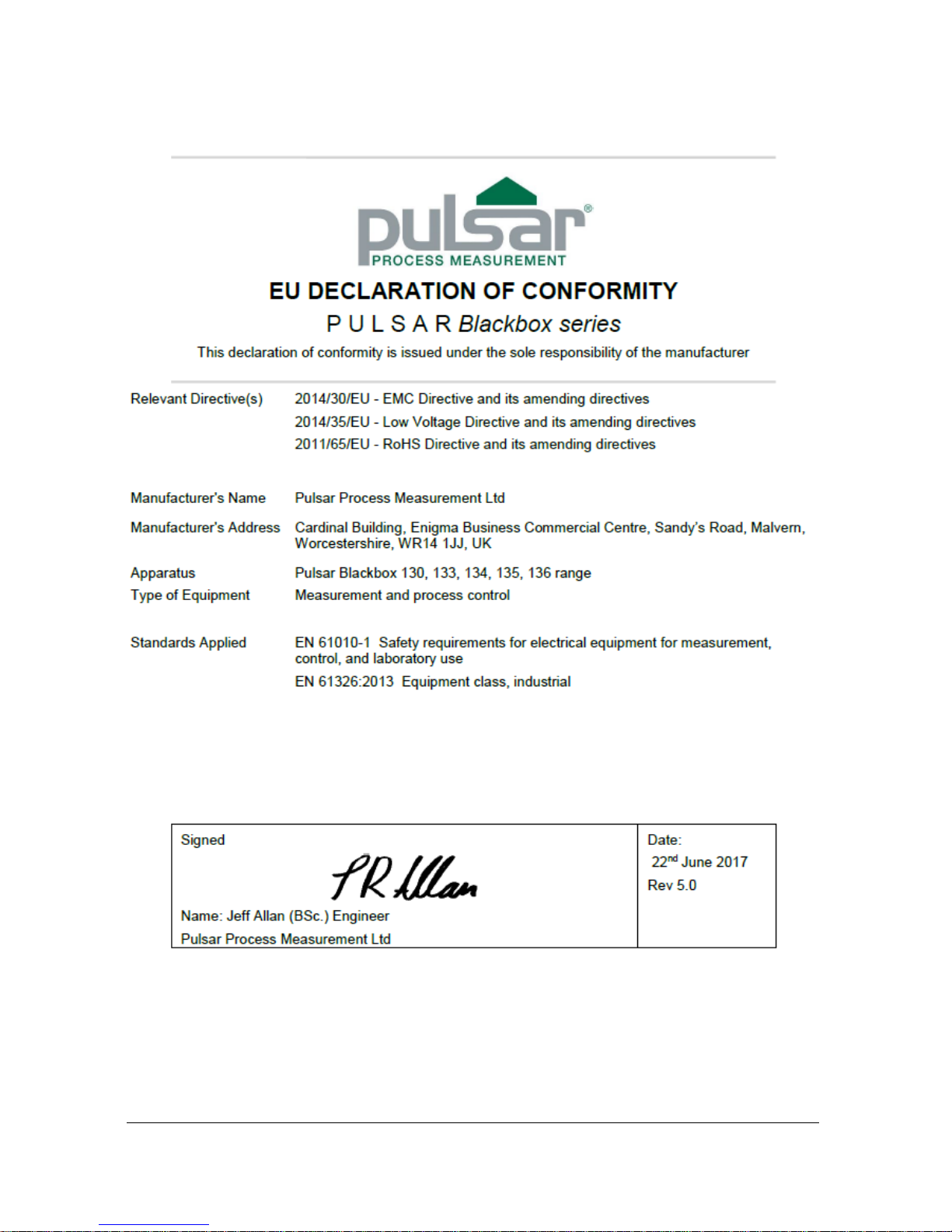
EC Declaration of Conformity ........................................................................................................................ 6
Chapter 2 Installation............................................................................................................................................ 7
Power Supply Requirements ........................................................................................................................... 7
Location ........................................................................................................................................................... 8
Dimensions ...................................................................................................................................................... 9
Standard Enclosure .................................................................................................................................. 9
Large Enclosure (optional) .................................................................................................................... 12
Terminal Connection Details ........................................................................................................................ 14
Power ..................................................................................................................................................... 15
Transducer.............................................................................................................................................. 15
Relay Outputs ........................................................................................................................................ 17
Current Output ....................................................................................................................................... 17
RS232 Serial Interface ........................................................................................................................... 17
Fuse Location ................................................................................................................................................ 17
Preparation for Operation .............................................................................................................................. 18
Maintenance ................................................................................................................................................... 19
Chapter 3 How To Use Your blackbox Level System .................................................................................... 20
PC Handheld Programmer (Standard).......................................................................................................... 20
Communication Port Configuration ..................................................................................................... 21
Handheld Communicator (Optional) ............................................................................................................ 21
On board integral Keypad and Display (Optional) ...................................................................................... 22
Operating the Controls .................................................................................................................................. 23
Display ................................................................................................................................................... 23
Keypad ................................................................................................................................................... 24
Run Mode ...................................................................................................................................................... 26
LED’s ..................................................................................................................................................... 27
Program Mode ............................................................................................................................................... 27
How to Access Program Mode ............................................................................................................. 28
Test Mode ...................................................................................................................................................... 30
LED’s ..................................................................................................................................................... 31
Using the RS232 Serial Interface .................................................................................................................. 31
Parameter Defaults ........................................................................................................................................ 32
Factory Defaults ..................................................................................................................................... 32
Chapter 4 Programming Guide .......................................................................................................................... 34
Level ............................................................................................................................................................... 34
Example 1 Level Measurement ............................................................................................................ 34
Example 2 Alternating Control (pump down) ..................................................................................... 36
Volume (Optional) ........................................................................................................................................ 38
Example 3 Volume Application ........................................................................................................... 38
Chapter 5 Parameter Guide ................................................................................................................................ 40
Menu System Diagrams ................................................................................................................................ 40
Top Level Menu .................................................................................................................................... 40
Application Menu .................................................................................................................................. 40
Relays Menu .......................................................................................................................................... 41
Page 6

Data Logs Menu .................................................................................................................................... 41
Volume Menu ........................................................................................................................................ 42
Display Menu ........................................................................................................................................ 43
Output Menu .......................................................................................................................................... 43
Compensation Menu ............................................................................................................................. 43
Stability Menu........................................................................................................................................ 44
Echo Processing Menu .......................................................................................................................... 44
System Menu ......................................................................................................................................... 45
Test Menu .............................................................................................................................................. 46
Parameter Listing ........................................................................................................................................... 47
Application Parameters ................................................................................................................................. 47
Operation ................................................................................................................................................ 47
Dimensions ............................................................................................................................................ 48
Remote Alarm........................................................................................................................................ 50
SMS Time .............................................................................................................................................. 51
Relay Parameters ........................................................................................................................................... 53
Relay Type ............................................................................................................................................. 53
Alarms .................................................................................................................................................... 54
Control.................................................................................................................................................... 57
Common Parameters ............................................................................................................................. 59
Data Log Parameters ..................................................................................................................................... 60
Temperature ........................................................................................................................................... 60
Volume (Optional) ........................................................................................................................................ 61
Conversion ............................................................................................................................................. 61
Breakpoints ............................................................................................................................................ 64
Tables ..................................................................................................................................................... 66
Display Parameters ........................................................................................................................................ 66
Options ................................................................................................................................................... 66
Failsafe ................................................................................................................................................... 67
Output Parameters ......................................................................................................................................... 68
Range ..................................................................................................................................................... 68
Operation ................................................................................................................................................ 68
Setpoint .................................................................................................................................................. 69
Limits ..................................................................................................................................................... 69
Trim ........................................................................................................................................................ 70
Failsafe ................................................................................................................................................... 70
Compensation Parameters ............................................................................................................................. 70
Offset ...................................................................................................................................................... 71
Temperature ........................................................................................................................................... 71
Stability Parameters ....................................................................................................................................... 72
Damping................................................................................................................................................. 72
Filters ...................................................................................................................................................... 72
Echo Processing Parameters ......................................................................................................................... 73
Transducer Status................................................................................................................................... 73
System Parameters ........................................................................................................................................ 74
Passcode ................................................................................................................................................. 74
System Information ............................................................................................................................... 74
Date & Time .......................................................................................................................................... 75
Daylight Saving Time ........................................................................................................................... 76
Test Parameters .............................................................................................................................................. 79
Simulation .............................................................................................................................................. 79
Hardware ................................................................................................................................................ 80
Chapter 6 Troubleshooting ................................................................................................................................ 82
Parameter Record .................................................................................................................................................. 83
Page 7

Page 1
Chapter 1 Start Here…
Congratulations on your purchase of a Pulsar blackbox 130 Level System.
This quality system has been developed over many years and represents the
latest in high technology ultrasonic level measurement and control.
It has been designed to give you years of trouble free performance, and a few
minutes spent reading this operating manual will ensure that your installation
is as simple as possible.
About this Manual
It is important that this manual is referred to for correct installation and
operation.
There are various parts of the manual that offer additional help or information
as shown.
Tips
At various parts of this
manual you will find tips to
help you.
Additional Information
Additional Information
At various parts of the manual, you will find
sections like this that explain specific things in
more detail.
References
See Also
References to other parts of the manual
Page 8
Page 2
About the blackbox range
The Pulsar blackbox is a non-contact Level Control System. It has been
designed to provide a new concept in low cost maintenance-free fit and forget
level measurement without any compromise on performance.
The blackbox is ideally suited to applications where level monitoring,
reporting, control or logging is required, with or without the need for a local
display.
The blackbox level system is available in a variety of different versions
offering a wide choice of output options.
The blackbox is very easy to use and may be calibrated quickly and simply
via a laptop, using the software supplied with the unit, or alternatively by
using the optional hand held calibrator, which connects to the unit via the
RS232 interface, and provides an on-board LCD display. Certain models are
also available with an optional LCD display and integral keypad fitted.
All models of the blackbox range can be used with any of the extensive range
of Pulsar dB transducers for distances up to 131ft (40m).
The blackbox range is designed to provide you with highly reliable
measurement in a robust and functional package that is easy to use and low in
cost.
Page 9

Page 3
Functional Description
The blackbox ultrasonic Level System sends a transmit pulse to the
transducer, which emits an ultrasonic pulse perpendicular to the transducer
face, and the returned echo is sent back to the blackbox. The time taken to
receive the echo is measured and the distance from the transducer face to the
surface being monitored is calculated.
The blackbox utilises the unique DATEM software (Digital Adaptive
Tracking of Echo Movement). This is a unique digital mapping technique
developed especially for Pulsar’s range of ultrasonic level and control
systems. It gives the system edge when identifying the “true target level” in
the face of competing echoes from pipes, pumps or other obstructions.
The blackbox can measure from 0.41ft (0.125m) to 131 feet (40m) from the
transducer to the surface being monitored, dependent on the application and
transducer used.
The blackbox can measure level, space or distance and provide a
representative output. When fitted with the optional display and keyboard
it can also measure and provide an output representative of volume. There are
two user definable relays, with individual setpoints, which can be
programmed to activate alarms or control functions, a mA output that can be
used for remote indication purposes and a RS232 port, so that the blackbox
can be programmed or monitored remotely by a PC or other equipment.
The blackbox can be programmed either by PC, via the RS 232 Serial
Interface, using the supplied software (standard) or by hand held calibrator
(optional) which is connected to the blackbox via the RS 232 interface.
Those units fitted with the optional on board display can be programmed via
the integral keyboard.
All the parameters are stored in non-volatile memory, so are retained in the
event of power interruption.
Page 10

Page 4
Product Specification
Physical
Standard Wall Mount Enclosure
Outside dimensions 5.12 x 5.12 x 2.36 inches
(130 x 130 x 60 mm)
Weight Nominal 1.4lbs (0.65 kg)
Cable entry detail underside fitted with 3 x M20, nylon cable
glands
Large Wall Mount Enclosure (optional)
Outside dimensions 5.12 x 7.09 x 3.35 inches
(130 x 180 x 85 mm)
Weight Nominal 1.65lbs (0.75 kg)
Cable entry detail underside fitted with 5 x M20, nylon cable
glands
Enclosure material/description Polycarbonate base with Polycarbonate lid,
flammability rating UL94-5V
Separation
Transducer cable extensions 3 conductor 20AWG screened
Nominal separation 3,280 ft. (1000m). For greater separation
distances please consult Pulsar
Environmental
Mounting Indoor/Outdoor
Relative Humidity (IP Rating) IP66 (NEMA 4X enclosure)
<35oC (95oF) at 93% relative humidity
Pollution Degree 2
Altitude 2000m maximum
Max. & min. temperature (electronics) -4ºF to 120ºF (-20 ºC to +50 ºC)
Flammable atmosphere approval Safe area: compatible with approved dB
transducers (see transducer spec' sheet)
Approvals
UL Certificate Number E257330
CE approval See EU Declaration of Conformity
Performance
Accuracy 0.25% of the measured range or
0.24" (6 mm) (whichever is greater)
Resolution 0.1% of the measured range or 0.08" (2 mm)
(whichever is greater)
Max. range Dependant on transducer (maximum 131ft
(40m) dB40)
Min. range Dependent upon transducer (minimum 0.41ft
(0.125m) dB 3)
Rate response fully adjustable
Echo Processing
Description DATEM (Digital Adaptive Tracking of Echo
Movement)
Page 11

Page 5
Outputs
Analogue output Isolated (floating) or non-isolated output of
4-20 mA or 0-20 mA into 1K (user
programmable and adjustable) 0.1%
resolution
Serial Port (Digital output) Full Duplex RS232 for programming and
data extraction
Volt free contacts, number and rating 2 form "C" (SPDT) rated at 2A at 115V AC
Display (optional) 2 x 12 alpha numeric
Programming
PC programming (standard) via RS232 using supplied software
Remote programming (optional) via RS232 using optional hand held
calibrator
On board programming (optional) via integral keypad
Programming security via passcode (user selectable and
adjustable)
Programmed data integrity via non-volatile RAM
Supply
Power supply 115 VAC +5% / -10% 50/60 Hz,
dc 10 - 28V
10W maximum power (typically 5W)
Overvoltage Category II
Fuses
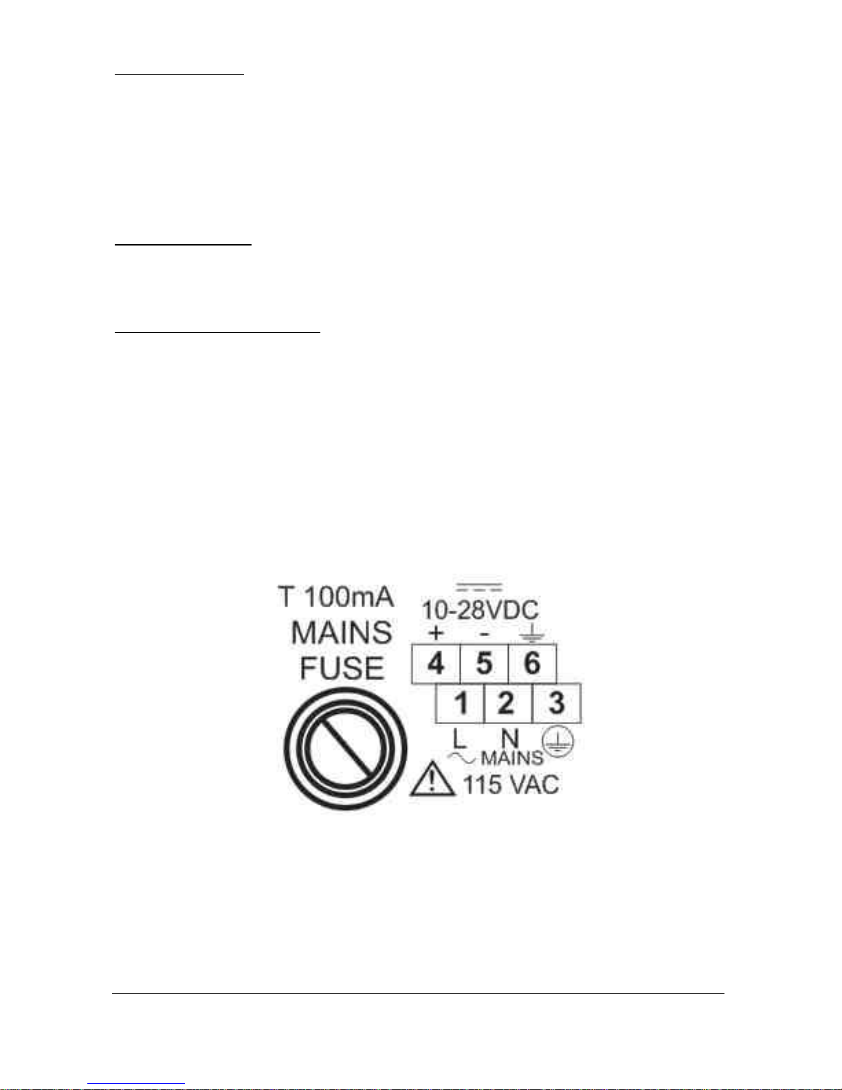
Mains (F1) 100 mA T at 115 VAC
DC (Battery) (F2) 1A Thermal (self resetting after power
removed). Not user replaceable
Transducer (F3, F5) Littelfuse 242 series 100mA Part No.
0242.100. This fuse is not user replaceable
and has a 4000A breaking capability to
comply with certification of the Exm version
of dB series transducers.
Remote Communicator
Power Supply Power supplied via blackbox RS232
interface.
Pulsar Process Measurement Limited operates a policy of constant development and
improvement and reserve the right to amend technical details as necessary.
Page 12
Page 6
EU Declaration of Conformity
Page 13
Page 7
Chapter 2 Installation
Power Supply Requirements
The blackbox can operate from AC supply or from a DC battery and is
designed for use in temperatures between -4oF to +140oF (-20oC to +50oC).
The AC is 115V +5%/-10%. The DC is 10-28V. In all cases the blackbox
will typically consume 5W of power, with a maximum of 10W. If the
blackbox has both an AC and DC supply available then the AC supply source
will be automatically sensed and used, should the AC supply be removed for
any reason then the DC supply will take over.
The AC and DC wiring should be completed using either 16 – 14AWG (1.5–
2.5mm2) stranded or 16 – 14AWG (1.5–4mm2) solid wire, with all terminals
being tightened to 4.5in. lbs. (0.5Nm).
An external supply isolator/circuit breaker (AC or DC) must be fitted and
labelled to identify the instrument to which it refers.
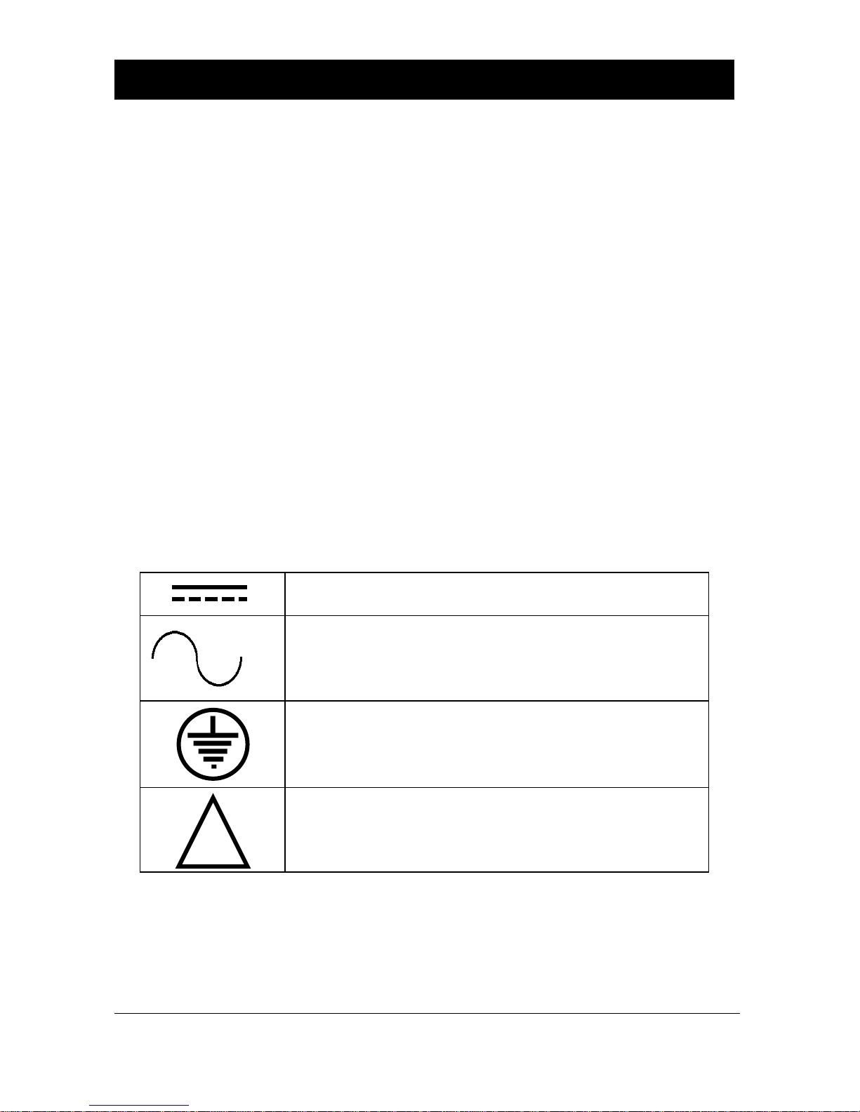
Safety Symbols
Detailed below are descriptions and meanings of safety/warning symbols that
are used on the blackbox 130 and in this manual.
Direct Current
Alternating Current
Protective Conductor Terminal
Caution (Refer to accompanying Documents)
!
Page 14
Page 8
Location
All electronic products are susceptible to electrostatic
shock, so follow proper grounding procedures during
installation.
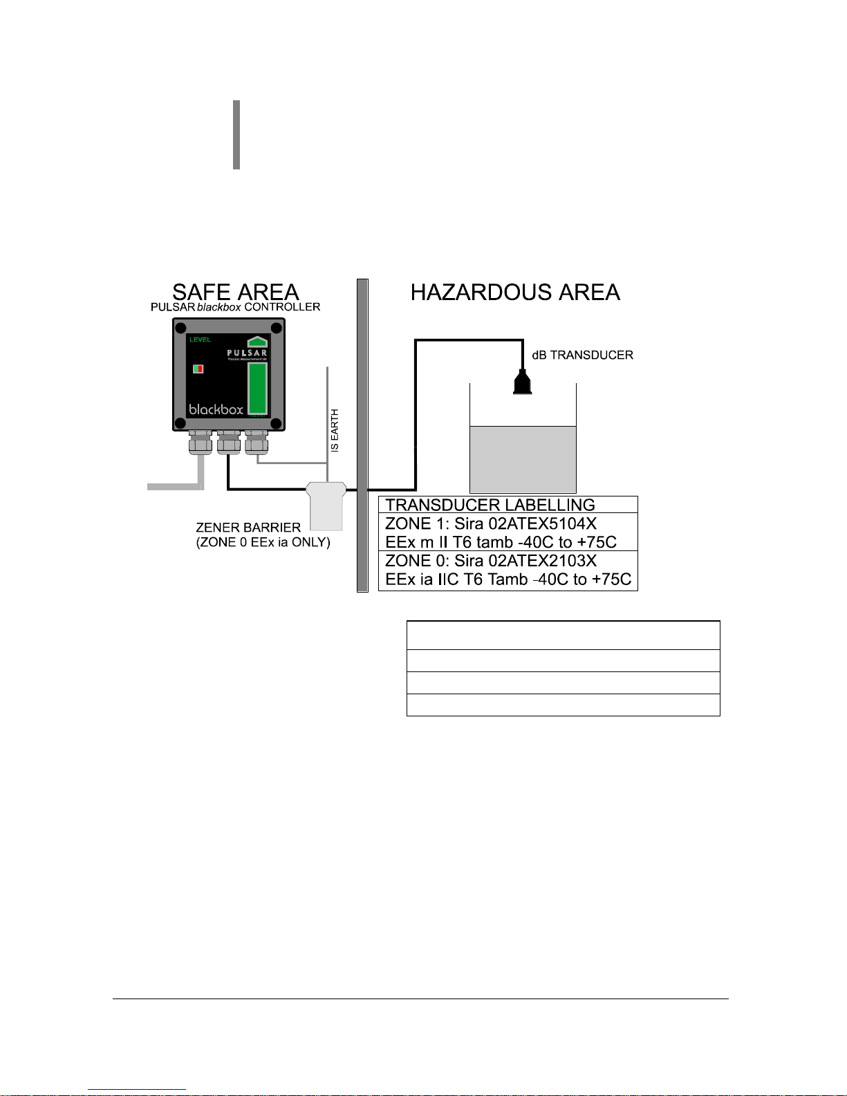
The blackbox level controller must be mounted in a non-hazardous (safe)
Area, and the transducer fitted in the hazardous area.
Note: the blackbox shown in the
above diagram is for illustrative
purposes only and may not be
representative of the actual blackbox
supplied.
FM APPROVED TRANSDUCERS
Class I, Div. 1, Group A, B, C & D
Class II, Div. 1, Group E, F & G
Class III
Page 15
Page 9
When choosing a location to mount the enclosure, bear in mind the following:
• Ensure that the blackbox is installed in a “Safe”, non-hazardous,
area.
• Easy access to the enclosure is maintained.
• The mounting surface is vibration-free.
• The ambient temperature is between -4ºF and 120ºF (-20ºC and
50ºC)
• There should be no high voltage cables or inverters close by.
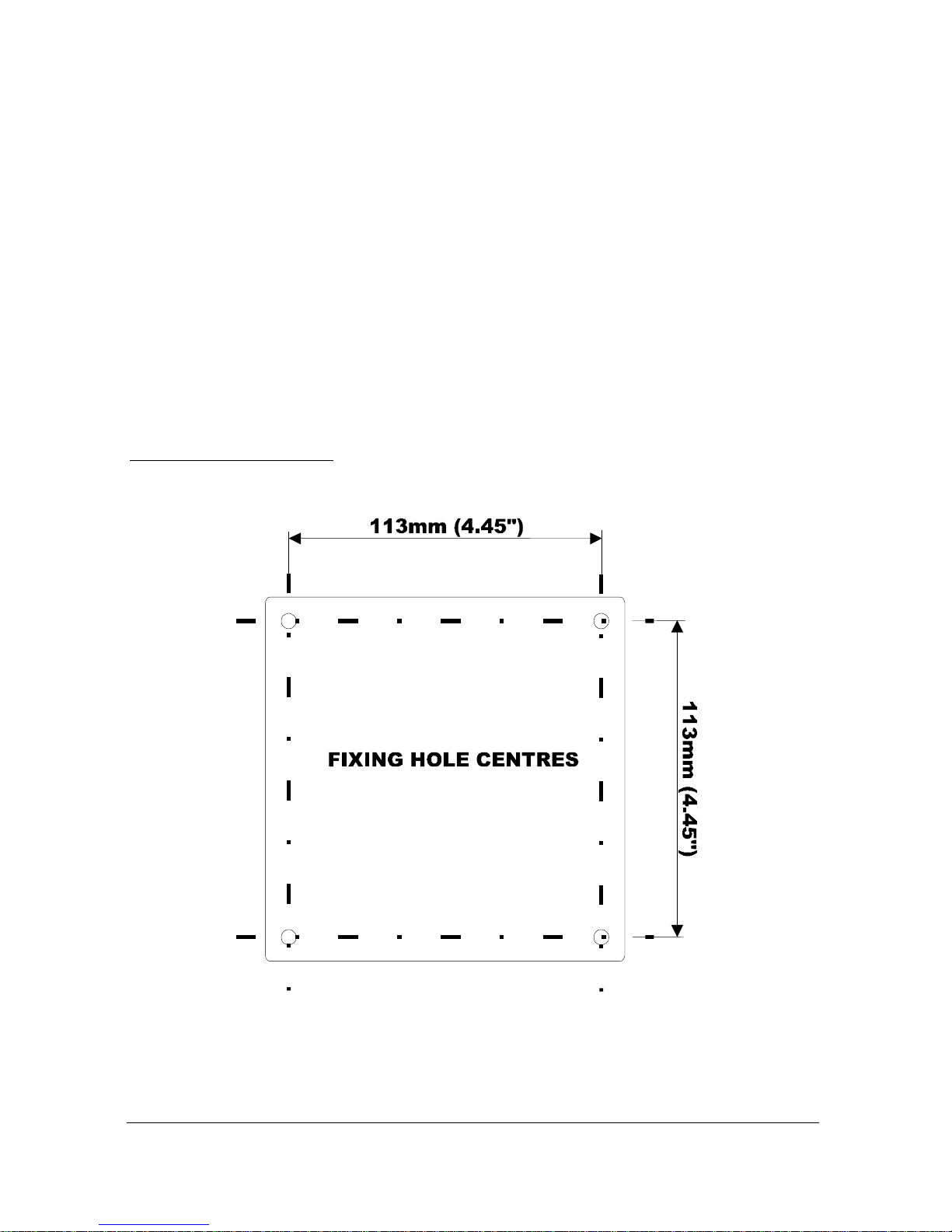
Dimensions
Standard Enclosure
The dimensions of the mounting holes are as shown below.
Page 16

Page 10
The blackbox should be mounted by drilling four holes suitable for size 8
pan or round headed screws. The screw length will be dependent on the wall
to which the blackbox is to be mounted to, if it is unclad use 1.5" long
screws with suitable wall fixings, if the wall is clad add the cladding
thickness to the 1.5" screw length.
Fit all four screws by removing the top cover to access the pre-moulded
mounting holes which are located in the corners of the base of the enclosure,
under the lid retaining screws.
Important Information
The enclosure lid screws should be tightened to 10in.lbs (1.1Nm).
Care should be taken not to over tighten the screws.
Page 17
Page 11
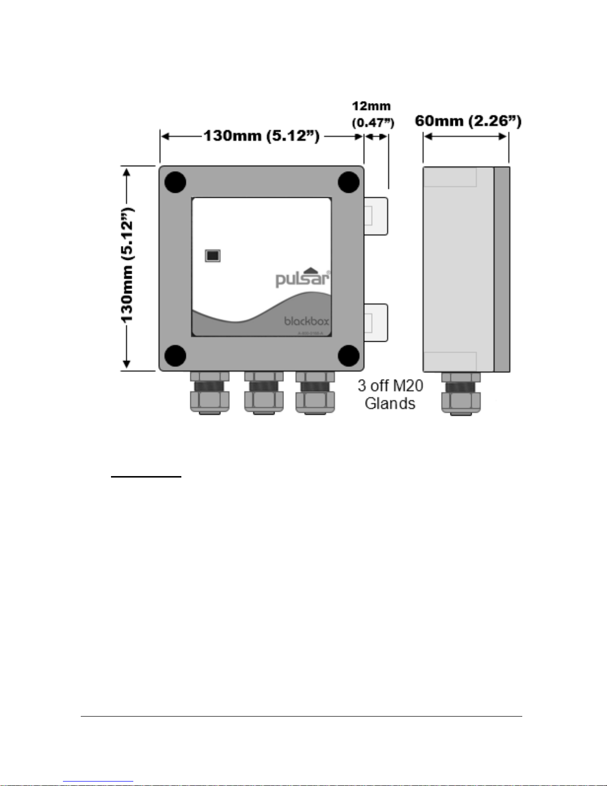
The full dimensions of the enclosure are as shown below.
Cable Entry
There are 3 x 20mm (0.79") cable glands, suitable for 6 – 12mm (0.24" –
0.63") cables, fitted to the base of the blackbox enclosure.
Page 18

Page 12
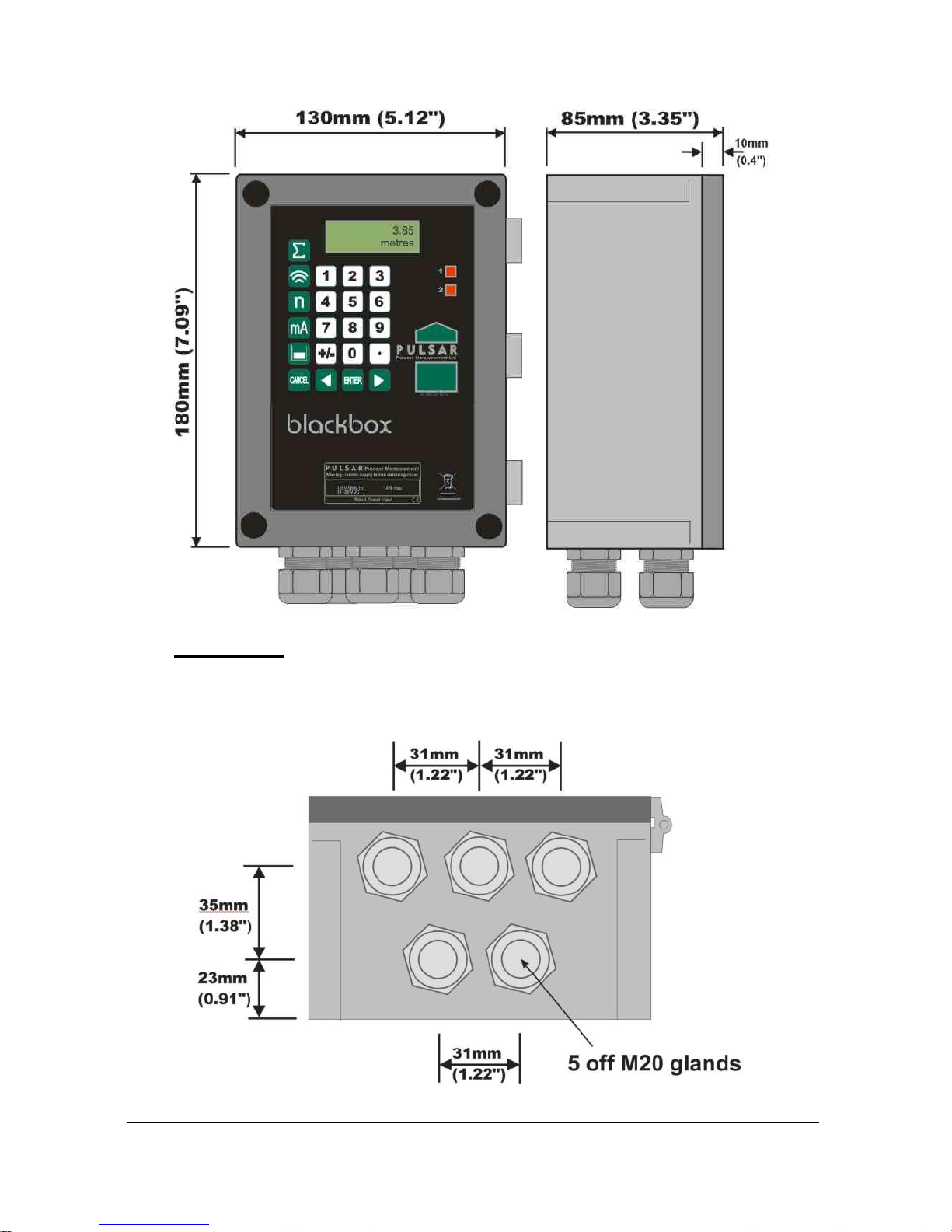
Large Enclosure (optional)
The dimensions of the mounting holes are as shown below.
Page 19
Page 13
The full dimensions of the enclosure are as shown below.
Cable Entry
There are 5 x 20mm (0.79") cable glands, suitable for 6 – 12mm (0.24" – 0.63")
cables, fitted to the base of the fitted to the base of the blackbox enclosure.
Page 20

Page 14
Terminal Connection Details
The terminal strip is as detailed below. There is also a wiring diagram attached
to the board directly underneath the terminal strip.
Important Information
All terminal connection screws should be tightened to 4.5in.lbs.
(0.5Nm).
Care should be taken not to over tighten the screws.
Page 21

Page 15
Terminal Connections
Power
The blackbox can operate from mains AC and automatically from a DC power
source or battery backup, in the event of power failure, or can be operated
permanently from DC or batteries.
The AC and DC wiring should be completed using either 16 – 14AWG (1.5–
2.5mm2) stranded or 16 – 14AWG (1.5–4mm2) solid wire.
An external supply isolator/circuit breaker (AC or DC) must be fitted and
labelled to identify the instrument to which it refers.
Transducer
The transducer should be installed, and connected, in accordance with the
installation instructions contained in the Transducer User Guide.
The entire range of, standard dB transducers are certified for use in hazardous
areas and different models, for each, are available for use in EEx m (Zone 1)
or EEx ia (Zone 0).
Wire the transducer to the blackbox transducer terminals as detailed below:
Red = Power (Terminal 19)
White = Signal (Terminal 20)
Black = 0 volts (Terminal 18)
Green (screen) = SCR (Terminal 17)
If splicing, it is recommended using a junction box with standard twisted,
shielded pair at 20 AWG.
When using 2 core screened extension cable, the Black and Green wires of
the transducer should be connected to the screen of the extension cable and
connected to the 0 volts’ terminal (Terminal 18).
Page 22

Page 16
When installing a transducer in a hazardous area use an approved transducer
suitable for the proposed application as detailed below:
FM
For EEx m (Zone 1) applications a transducer certified to FM Class I Div 1
Group A, B, C & D, ClassII Div 1 Group E, F & G, Class III is used, and
must be supplied via a 1500A breaking fuse, which is fitted as standard to
the blackbox level controller.
Restrictions do not use in the presence of these groups of Chemicals,
Aliphatic Hydro Carbons, Ketones or Esters
For EEx ia (I.S.) a transducer certified to FM Class I Div 1 Group A, B, C
& D, ClassII Div 1 Group E, F & G is used, which must be connected to the
blackbox via an external Zener barrier.
ATEX
For EEx m (Zone 1) applications a transducer certified to Sira
02ATEX5104X is used, and must be supplied via a 4000A breaking fuse,
which is fitted as standard to the blackbox level controller.
For EEx ia (Zone 0) a transducer certified to Sira 02ATEX2103X is used,
which must be connected to the blackbox via an external Zener barrier.
See transducer label for certification details.
Important Information
Please note that if the output of the ultrasonic transducers used with
blackbox are capable of emitting sound pressure levels in excess of
85dBA (above a reference sound pressure level of 20µPA), then the
blackbox must be located remote from the transducer such that a sound
pressure level of 85dBA is not exceeded when standing at the blackbox
in the operator’s position.
Page 23
Page 17
Relay Outputs
The two relays can be programmed to a variety of alarm and control functions.
The relay contacts are all rated at 2A at 115V AC. Wiring should be
completed by using suitable cable, to meet the specified 115V AC 2A contact
rating, up to maximum size of 14AWG. All connections should be such that
the short circuit capacity of the circuit to which they are connected, is limited
by fuses rated so that they do not exceed the relay rating.
Current Output
This is an isolated mA output of 4 - 20mA or 0 - 20mA, and the load should
not exceed 1K.
RS232 Serial Interface
The serial interface is used to programme the blackbox either via a PC
(standard) using the software supplied or alternatively using the hand-held
calibrator (optional).
Fuse Location
The mains fuse is located, on the bottom board, to the left of the mains
terminals, as illustrated below.
Page 24

Page 18
Important Information
Before applying AC power (mains), make sure the supply is 115 VAC
+5% / -10%
Never operate the blackbox with terminal access exposed.
An external switch or circuit breaker should be installed near to the
blackbox to allow the supply to be removed during installation and
maintenance. In addition, the relay contacts should also have a means
of isolating them from the blackbox.
Interconnecting cables must be adequately insulated in accordance
with local regulations. Strip back 30 mm of the outer insulation of the
cable. Strip 5 mm of insulation from the end of each conductor. Twist
all exposed strands of the conductor together. Insert the stripped
conductor into the terminal block as far as it will go and tighten the
terminal block screw. Ensure that all strands are firmly clamped in the
terminal block and that there is no excess bare conductor showing,
and no stray strands.
Important Information
If the equipment is installed or used in a manner not specified in this
manual, then the protection provided by the equipment may be
impaired.
Preparation for Operation
Before switching on, check the following:
✓ The blackbox is mounted correctly and is in a ‘safe’ area.
✓ The power supply is correctly installed.
✓ The relays are connected correctly.
Page 25

Page 19
Maintenance
There are no user serviceable parts inside your blackbox, except the mains
power fuse. If you experience any problems with the equipment, then please
contact Pulsar Process Measurement for advice.
Important Information
Please note that the on-board Lithium battery, mounted to the
processor PCB, is not user serviceable.
To clean the equipment, wipe with a damp cloth. Do not use any solvents on
the enclosure or transducer.
Important Information
The unique DATEM software comes into operation as soon as
power is applied, and is designed to monitor a moving level or
target with the transducer in a fixed position.
If, after any period of use, it should become necessary to move the
transducer, for any reason, from its original operating position,
switch off the blackbox, before proceeding, to prevent any
undesirable updates to the DATEM trace. If after moving the
transducer the reading is not as expected, please refer to Chapter 6
Troubleshooting.
Page 26
Page 20
Chapter 3 How To Use Your blackbox Level System
In order to view or change parameter values one of the following methods
must be used:
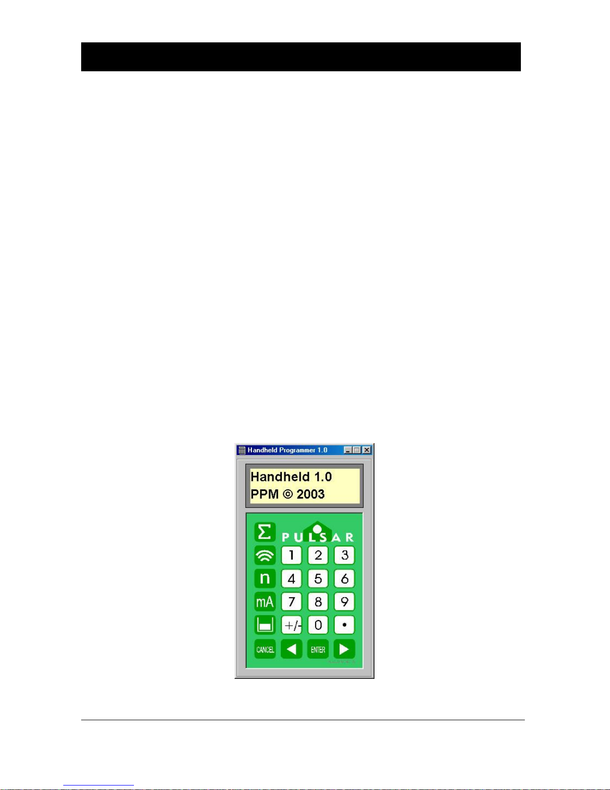
PC Handheld Programmer (Standard)
Your blackbox 130 comes complete with the PC Handheld Programmer
software, contained on CD. Insert the CD into the CD drive of the PC intended
to be used to carry out the programming of the blackbox and install the
software, following the on-screen instructions. Once the software is installed
connect the computer via its serial port to the blackbox RS232 serial interface
RJ11 connector, located on the terminal connector strip, inside the blackbox
enclosure. Double click the ‘Handheld Programmer’ icon, installed on your
desktop and the PC will automatically connect to the blackbox. Once
connected you will briefly see the message illustrated on the display below
which, after connecting successfully, will then change to display the current
measurement, dependent on mode and measurement unit's chosen. When
using the PC Handheld Programmer software, keypad input can be achieved
by using a ‘mouse’ or similar device to place the cursor over the relevant key
followed by a ‘left’ click, alternatively numeric detail can be entered directly
from the PC keyboard as can ‘ENTER’ and ‘CANCEL’ (Esc. Key).
Page 27
Page 21
Communication Port Configuration
If the PC Handheld Programmer fails to connect to the blackbox unit you
may need to change the communications port that is being used, to do this
‘right click’ on the PC Handheld Programmer keypad and a ‘pop up’ menu
will appear allowing you to select the appropriate communications port.
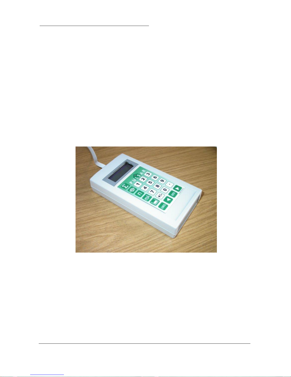
Handheld Communicator (Optional)
The optional Handheld communicator can be used to programme any number
of blackbox units and works in a similar way to the PC Software. Connect the
Handheld Communicator, with the cable supplied, to the RS232 interface via
the RJ11 connector located on the terminal connector, inside the blackbox
enclosure. Once connected you will briefly see a message, similar to that as
seen when using the PC Software which, after connecting successfully, will
then change to display the current measurement, dependent on mode and
measurement unit's chosen.
Page 28
Page 22
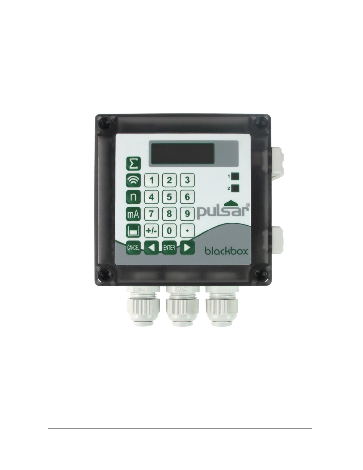
On board integral Keypad and Display (Optional)
When fitted, the blackbox can be programmed directly via the integral
keypad.
Page 29

Page 23
Operating the Controls
Display
The display in all cases is identical, the only difference being is that both the
PC Programming Software (standard) and the Hand-Held Calibrator
(optional) need to be connected to the blackbox via the RS232 interface,
whereas the on-board keypad and display (optional) are permanently
connected to the blackbox provides information on the current mode of
operation.
When in the Run Mode it will display the current level reading and its units
of measure, along with status messages with regards to the Transducer, Echo
reception and Fail Safe Mode. When in the Program mode the display is used
to read information on the Menu System, Parameter Number and parameter
details and values, which can be entered. During Test Mode, the display is
used to monitor the simulated level.
1234.56
mm
1) Main Display, 6-digit numeric display:
Run Mode, current measurement displayed, dependent on mode and
measurement unit's chosen, and value of Hot Key function selected.
Program Mode, displays parameter number and values entered for
parameters.
Test Mode, displays simulated level.
2) Auxiliary Display, scrolling twelve-digit alpha numeric display
Run Mode, displays measurement units (P104), status messages on
signal and transducer, detail of Hot Key function selected.
Program Mode, displays Menu and Sub Menu headings, parameter
3) details and options.
1
2
Page 30

Page 24
Keypad
Hot Keys
There are five hot keys on the keypad, which can be used to quickly access
common parameters for viewing only, while in Run Mode. Pressing the hot
key once will display the first parameter, then repeated pressing will display
subsequent parameters, as available, then the blackbox reverts to Run Mode.
In program mode, they have different functions, the functions are shown
below.
Hot
Key
Run Mode
Program Mode
Not used with blackbox 130.
Not used with blackbox
130.
Displays echo confidence, echo
strength, H.A.L.L., average
noise, peak noise or temperature.
Not used with blackbox
130.
Not used with blackbox 130.
Reset parameter to default
setting.
Instantaneous mA output.
Not used with blackbox
130.
Dependant on application
displays Distance, Level, Space
or Volume (optional) in units of
measurement.
Not used with blackbox
130.
Not used with blackbox 130.
Takes you to the last
parameter edited, when you
first enter program mode.
Gives details of unit type,
software revision and serial
number.
Enter Decimal Point.
Page 31

Page 25
Menu Keys
The menu keys are used to navigate around the built-in menu system and have
the following functions:
Menu Key
Function
1) Arrow keys for moving left and right around the menu
system.
2) Used in test mode to simulate the level moving up and
down.
1) Used to confirm each action (for example select a menu
option) or when entering a parameter number or value.
2) Used to confirm questions asked by your blackbox such
as before restoring factory defaults.
Used to navigate up a level in the menu system, and back
to run mode.
Used to cancel a value entered in error.
Numeric Keys
These keys are used for entering numerical information during programming.
Page 32

Page 26
There are two main operating modes for your blackbox, Run Mode and
Program Mode. There is also a Test Mode, used for checking the set-up. All
modes are now described.
Run Mode
This mode is used once the blackbox has been set up in program mode. It is
also the default mode that the unit reverts to when it resumes operation after
a power failure.
When the blackbox is switched on for the first time, it will provide an output
proportional to the distance from the transducer to the target, in feet. All relays
by default are switched off.
If either the PC Programming Software (standard) or the Hand-Held
Calibrator (optional), are connected to the blackbox, via the RS232 interface,
while the blackbox is in the RUN mode then the current measurement will be
displayed, dependent on mode and measurement unit's chosen. Models fitted
with the optional LCD display and integral keypad will also display the
current measurement, dependent on mode and measurement unit's chosen.
After programming is complete, any relays that are set will operate when the
measurement reaches the relevant setpoint.
Page 33

Page 27
LED’s
There are two LED’s which can be seen through the lid, of the blackbox
enclosure, which will indicate the operational status of the unit when in RUN
mode, as follows:
blackbox without on board display (standard).
LED 1
Green
LED 2
Red
Run Mode
Off
Off
No power to unit
Constant
On
Constant
On
Internal Error
Slow
Flashing
Slow
Flashing
Transducer fault
Off
Slow
Flashing
Failed Safe /Loss of Echo
Slow
Flashing
Off
Healthy signal unit working
normally.
blackbox with on board display (optional).
LED 1
LED 2
Run Mode
Off
Off
Relays are in there OFF state.
Constant
On
Off
Relay 1 in its ON state
Off
Constant
On
Relay 2 in its ON state
Program Mode
This mode is used to set up the blackbox or change information already set.
You must use either the PC Software supplied (standard) or alternatively the
unit can be set up with a Hand-Held Calibrator (optional), both of which must
be connected to the blackbox via the RS 232 Serial Interface.
Those models fitted with the optional display can be set up by using the
integral keypad on the unit.
Entering a value for each of the parameters that are relevant to your
application provides all the programming information.
Page 34

Page 28
How to Access Program Mode
To enter program mode, you simply enter the passcode, via the keypad on
the PC Programming Software (standard), Hand Held Calibrator (optional) or
integral keypad (optional), followed by the ENTER key. The default passcode
is 1997, so you would press the following:
Note
There is a time-out period of 15 minutes when in program mode,
after which time run mode will be resumed if you do not press any
keys.
There are two means of editing parameters, directly or using the menu system.
Each is now described.
Using the Menu System
The menu system has been designed to make the changing of parameters very
simple. There are two levels of menu: Main Menu and Sub Menu.
On the display, there is a line of text that shows the menu system. Pressing
the arrow keys scrolls the display between the top-level menu items, (as
shown below, starting at Application).
As you press the cursor keys to scroll left and right between these, you can
press ENTER at any time to select it and take you to the sub-menu.
Each of these options, along with their sub-menus are described in Chapter 5,
Parameter Guide. When you move down into the sub-menu, you can scroll
round using the arrow keys, press ENTER to go to the required section of
parameters.
Application
Relays
Data Logs
Volume
(optional)
Display
System
Echo
Process
Stability
Compensation
Test
Output
Page 35

Page 29
Once you have reached the relevant section, scroll through the parameters,
and enter the necessary information. To enter the information, use the numeric
keys and press ENTER and you will see the message “Saved!”, if you press
CANCEL, then no change will be made, and the message “Unchanged!!”
will be displayed.
When you have finished, press CANCEL to go back to the previous level.
When you have reached the top level, then the blackbox will ask for
confirmation before allowing you to go back into run mode. This is done by
pressing ENTER at the display prompt.
Directly Editing Parameters
If you already know the number of the parameter, that you wish to look at or
edit, simply type the number in at any time while you are in the menu system.
Thus, if you are in either the menu or sub-menu level by pressing a numeric
key, you can enter the parameter number directly and jump straight there. You
cannot type a parameter number while at parameter level, only at one of the
two menu levels.
When you are at a parameter, the text line rotates automatically displaying the
parameter name, number, the applicable units and the maximum and
minimum figure you can enter. The top line shows the value you are setting.
Once you have accessed a parameter, you can either just look at it, or change
it.
Once a parameter has been changed, press ENTER and you will see the
message “Saved!” If you press CANCEL, then no change will be made, and
the message “Unchanged!!” will be displayed.
TIP
You can jump straight to the last
parameter you edited, by pressing
‘+/-’ when you first enter program
mode.
Page 36

Page 30
Test Mode
Test mode is used to simulate the application and confirm that all parameters
and relay setpoints have been entered as expected. During simulation, there is
a choice of whether the relays will physically change state (hard simulation)
or not (soft simulation), the LED’s will always change state to indicate that
the relay setpoints have been activated, and the output will change in
accordance to the chosen mode of operation. If you wish to test the logic of
the system that the relays are connected to then select hard simulation, but
if you don’t want to change the relay state, then select a soft simulation.
There are two simulation modes, automatic and manual. Automatic
simulation will move the level up and down between empty level and
maximum span, whereas manual simulation will allow you to move the level
up and down using the arrow keys.
To enter simulation, first go to program mode. Then, using the menu system,
select menu item ‘Test’ then sub-menu item ‘Simulation’. Simply change the
value of the parameter P980 to one of the following:
1= Manual soft simulation
2= Automatic soft simulation
3= Manual hard simulation
4= Automatic hard simulation
To return to program mode, press CANCEL and test mode will end.
When in manual simulation, by default test mode will move the level by
0.25m steps. Altering the increment (P981) will change this value.
In automatic mode, the rate at which the level moves up and down is set by
the increment (P981) in feet and the rate (P982) in minutes, which can be
changed to make the level move up and down faster. E.g. if increment (P981)
is set for 0.25ft and rate (P982) is set to 1 min then the level will increase or
decrease at a rate of 0.25ft/min. To make the simulated level move slower,
decrease the value in increment (P981) or increase the value in rate (P982).
To make the simulated level move faster, increase the value in increment
(P981) or decrease the value in rate (P982).
Page 37

Page 31
LED’s
There are two LED’s which can be seen through the lid, of the blackbox
enclosure, which will indicate the status of the relays when in simulation as
follows:
blackbox without on board display (standard).
Green
Red
Run Mode
Off
Off
Relays are in their OFF state.
Off
Constant
On
Relay 1 in its ON state
Constant
On
Off
Relay 2 in its ON state
Constant
On
Constant
On
Relay 1 and 2 in their ON state
blackbox with on board display (optional).
LED 1
LED 2
Run Mode
Off
Off
Relays are in their OFF state.
Constant
On
Off
Relay 1 in its ON state
Off
Constant
On
Relay 2 in its ON state
Constant
On
Constant
On
Relay 1 and 2 in their ON state
Using the RS232 Serial Interface
The RS232 serial interface is used to program the blackbox, and communicate
between the blackbox and a PC using the optional blackbox PC and other
associated Pulsar software packages, to obtain information such as data
logging and view echo traces upload, download and save parameter files. In
addition, it can also be used to control or obtain information using a standard
PC or other computer based equipment. To do so, the settings for control are
as follows: baud rate 19,200, 8 data bits, no parity, 1 stop bits.
The device should be connected to the RS232 Interface via the RJ11
connector as shown in Chapter 2 Installation.
Page 38

Page 32
Parameter Defaults
Factory Defaults
Factory Defaults
When first installing the blackbox, or subsequently moving or using
the unit on a new application, before proceeding to program the unit
for its intended application it is recommended that you ensure that
all parameters are at their default values by completing a Factory
Defaults P930, as described in Chapter 5 Parameter Guide.
When you first switch the blackbox on it will provide an output proportional
to the distance from the face of the transducer to the surface. All relays are
set OFF.
The date (P931) and time (P932) in the blackbox were set at the factory, but
may need checking, and amending if, for example the application is in a time
zone other than GMT, see Chapter 5 Parameter Guide for full details.
TIP
In some applications, it is simplest to empty
the vessel, take a reading from the blackbox
for distance and then setup the empty level
to this figure.
Once you are satisfied with the installation, and the blackbox is reading what
you would expect in terms of distance from the face of the transducer to the
material level, then you can proceed with programming, for the intended
application. It is sensible to program all the required parameters at the same
time. The system will be then set-up.
Note that the span is automatically calculated from the empty level, so the
empty level should be entered first.
Page 39

Page 33
This page is left blank intentionally
Page 40

Page 34
Chapter 4 Programming Guide
Level
Example 1 Level Measurement
empty distance (P105), 11.0 feet
100%, span (P106), 10.0 feet
(output = 20mA)
high alarm on (P213), 8.5 feet
high alarm off (P214), 8.0 feet
low alarm off (P224),1.5 feet
low alarm on (P223),1.0 feet
0% , empty level (output = 4mA)
In this example, the blackbox and dB6 is being used to monitor a moving
level within a vessel and is required to provide a 4 to 20mA output
proportional to the level, over a range of 10.0 feet. In addition, when the level
rises to 8.5 feet, Relay ‘1’ is required to give a high alarm and rest when the
level falls to 8.0 feet. In the event that the level should fall to 1.0 feet then
Relay ‘2’ is to give a low alarm and reset once the level rises to 1.5 feet.
Page 41

Page 35
To program the blackbox for this Example, proceed as follows.
Access the Program Mode
Key in the passcode 1997 and press ENTER
Using the menu system access the parameters, as detailed below, and select
the relevant options and ENTER.
Top Level
Menu
Sub Menu
Parameter Detail
Selected
Value
Application
Operation
P100 Mode
2 = Level
P101 Xducer
2 = dB6
Distances
P104 Measnt Units
4 = feet
P105 Empty Level
11.0
P106 Span
10.0
Relays
Relay 1
P210 Relay 1 Type
1 = Alarm
P211 R1Function
1 = Level
P212 R1 ID
2 = High
P213 R1 Set 1
8.5
P214 R1 Set 2
8.0 Relay 2
P220 Relay 1 Type
1 = Alarm
P221 R1Function
1 = Level
P222 R1 ID
4 = Low
P223 R1 Set 1
1.0
P224 R1 Set 2
1.5
Programming is now complete and the unit can be returned to the run mode,
press CANCEL until Run Mode? Is displayed on the display press ENTER,
and the blackbox will return to the Run Mode.
Note
The 4 to 20mA output will be automatically set to the value of P106
Span, with 4mA being representative of 0% of Span (zero level) and
20mA 100% of Span (Full level).
Page 42

Page 36
Example 2 Alternating Control (pump down)
A sump is typically used to temporarily hold water or effluent, and when the
level reaches a specific point, the sump is pumped down, with the fluid being
transferred to another process.
empty distance (P105), 15.0 feet
100%, span (P106), 13.5 feet
(output = 20mA)
pump 1+2 off (P214, 224), 1.5 feet
0% , empty level (output = 4mA)
pump 2 on (P 223), 6.0 feet
pump 1 on (P 213), 4.0 feet
In this example a blackbox with dB6 is being used to control pumps on a
pump down application, there are two pumps, and the duty pump is to be
alternated between the pumps.
This will operate as follows. During normal operation, pump 1 will come on
at 4.0 feet, and pump down to 1.5 feet. The setpoints are then shifted to pump
2, which will come on first next time.
During peak periods, when pump 1 cannot cope, pump 1 will come on at 4.0
feet, pump 2 will come on at 6.0 feet, and pump down to 1.5 feet. The
setpoints are then shifted to pump 2, which will come on first next time.
The 4 to 20mA output will be representative of level.
Page 43

Page 37
To program the blackbox for this Example, proceed as follows.
Access the Program Mode
Key in the passcode 1997 and press ENTER
Using the menu system access the parameters, as detailed below, and select
the relevant options and ENTER.
Top Level
Menu
Sub Menu
Parameter Detail
Selected
Value
Application
Operation
P100 Mode
2 = Level
P101 Xducer
2 = dB6
Distances
P104 Measnt Units
4 = feet
P105 Empty Level
15.0
P106 Span
13.5
Relays
Relay 1
P210 Relay 1 Type
2 = Control
P211 R1Function
1 = General
P212 R1 ID
2 = Alternate
P213 R1 Set 1
4.0
P214 R1 Set 2
1.5 Relay 2
P220 Relay 1 Type
2 = Control
P221 R1Function
1 = General
P222 R1 ID
2 = Alternate
P223 R1 Set 1
6.0
P224 R1 Set 2
1.5
Programming is now complete and the unit can be returned to the run mode,
press CANCEL until Run Mode? Is displayed on the display press ENTER,
and the blackbox will return to the Run Mode.
Note
The mA output will be automatically set to the value of P106 Span,
with 0 or 4 mA being representative of 0% of Span (zero level) and
20mA 100% of Span (Full level).
Page 44

Page 38
Volume (Optional)
Example 3 Volume Application
Only available on blackbox 130D, fitted with optional LCD display and
integral keypad.
A cylindrical tank with a diameter of 2m and a flat base that is typically used
to temporarily hold liquid, and you wish to know the volume of liquid. You
also require a high and low alarm.
empty distance (P105), 13.5 feet
100%, span (P106), 11.5 feet
high alarm on (P213), 10.0 feet
high alarm off (P214), 9.0 feet
low alarm off (P234), 2.0 feet
low alarm on (P233), 1.0 feet
0%, empty level
In this example, if the level rises to 10.0 feet, then the high-level alarm (relay
1) will come on until the level drops to 9.0 feet. If the level falls to 1.0 feet,
then the low-level alarm (relay 2) will come on until the level rises to 2.0 feet.
The display will show the volume of fluid in the tank and the mA output will
be representative of Volume where 4mA = empty (0%) and 20mA = Max
Volume (100%).
Page 45

Page 39
To program the blackbox for this Example, proceed as follows.
Access the Program Mode
Key in the passcode 1997 and press ENTER
Using the menu system access the parameters, as detailed below, and select
the relevant options and ENTER.
Top Level
Menu
Sub Menu
Parameter Detail
Selected Value
Application
Operation
P100 Mode
5 = Volume
P101 Xducer
2 = dB6
Distances
P104 Measnt Units
4 = feet
P105 Empty Level
13.5
P106 Span
11.5
Relays
Relay 1
P210 Relay 1 Type
1 = Alarm
P211 R1Function
1 = Level
P212 R1 ID
2 = High
P213 R1 Set 1
10.0
P214 R1 Set 2
9.0
Relay 2
P220 Relay 1 Type
1 = Alarm
P221 R1Function
1 = Level
P222 R1 ID
4 = Low
P223 R1 Set 1
1.0
P224 R1 Set 2
2.0
Volume
Conversion
P600 Vessel Shape
0 = Cyl.Flat Base
P601 – P603
Vessel Dimensions
Enter dimensions as
required
P604 Calc. Volume
Shows the volume
as calculated by the
blackbox
P605 Volume Units
Select as required
P606 Correction
Factor
Enter value of any
correction factor
e.g. specific gravity
of material
P607 Max. Volume
Displays the Max.
Vol. as calculated
by the blackbox
Programming is now complete and the unit can be returned to the run mode,
press CANCEL until Run Mode? Is displayed on the display press ENTER,
and the blackbox will return to the Run Mode.
Page 46

Page 40
Chapter 5 Parameter Guide
This chapter describes all of the parameters contained in your blackbox.
Menu System Diagrams
Shown below is a set of charts to show you how all the various parts can be
found using the menu system.
Top Level Menu
Application Menu
Application
Relays
Data Logs
Volume
(optional)
Display
System
Echo
Process
Stability
Compensation
Test
Output
Operation
Distances
P100
Mode
P101
Transducer
P104
Measurement
Units
P105
Empty Level
P106
Span
P107
Near Blanking
P108
Far Blanking
Remote Alarm
P985 Tel. No 1
SMS Time
P986 Tel. No 2
P987 Tel. No 3
P988 Call Type
P995 Interval
P996 SMS Start
P997 SMS Stop
P998 SMS Days
P102
Material
Page 47

Page 41
Relays Menu
Data Logs Menu
Relay 1
P210 R1 Type
P211 R1 Function
P212 R1 ID
P213 R1 Set 1
P214 R1 Set 2
P217 R1 Closures
P218 R1 Failsafe
Relay 2
P220 R2 Type
P221 R2 Function
P222 R2 ID
P223 R2 Set 1
P224 R2 Set 2
P227 R2 Closures
P228 R2 Failsafe
Temperature
P580 Min. Temp
P581 Min. Temp. Date
P582 Min. Temp. Time
P583 Max. Temp.
P584 Max. Temp. Date
P585 Max. Temp. Time
P586 Current Temperature
Page 48

Page 42
Volume Menu
Only available on blackbox 130D, fitted with optional LCD display and
integral keypad.
Conversion
P600
Vessel Shape
P601
As Required
Vol. Dimension 1
P602
As Required
Vol. Dimension 2
P603
As Required
Vol. Dimension 3
P604
Calculated
Volume
P605
Volume Units
P606
Correct. Factor
P607
Max. Volume
P612, 614, 616, 618,
620, 622, 624, 626,
628, 630, 632, 634,
636, 638, 640, 642,
644, 646, 648, 650,
652, 654, 656, 658,
660, 662, 664, 666,
668, 670
Level Bkpts. 2 to 31
Breakpoints
P610
Level Bkpt. 1
P611
Vol. Bkpt. 1
P613, 615, 617, 619,
621, 623, 625, 627,
629, 631, 633, 635,
637, 639, 641, 643,
645, 647, 649, 651,
653, 655, 657, 659,
661, 663, 665, 667,
669, 671
Vol. Bkpts. 2 to 31
P672
Level Bkpt. 32
P673
Vol. Bkpt. 32
Tables
P696
Reset
Bkpts.
Page 49

Page 43
Display Menu
Output Menu
Compensation Menu
Range
Operation
Setpoint
Limits
Trim
Fail Safe
P830
Out
Range
P831
Out Mode
P834
Low
Value
P836
Low
Limit
P835
High
Value
P837
High
Limit
P838
Low
Trim
P839
High
Trim
P840
Fail
Mode
Offset
Temperature
P851
Measurement
Offset
P852
Temperature
Source
P854
Fixed
Temperature
P800
Display Units
P801
Decimal Places
P802
Display Offset
P804
Display Conversion
Options
P808
Fail Mode
P809
Fail Time
Fail Safe
Page 50

Page 44
Stability Menu
Echo Processing Menu
Damping
Filters
P870
Fill Damping
P871
Empty Damping
P881
Fixed Distance
P882
Process Filter
Transducer
(Xdr.)
Status
P900
Xdr. 1 Status
P901
Echo
Confidence
P902
Echo Strength
P903
Average Noise
P904
Peak Noise
P905
Sensitivity
P906
Side Clearance
Page 51

Page 45
System Menu
Passcode
System
Info
Date
&
Time
Daylight
Saving
P921
Enable
Code
P926
Software
Revision
P931
Date
P970
DST
Enable
P922
Passcode
P927
Hardware
Revision
P928
Serial
Number
P929
Site
Ident.
P930
Factory
Default
P932
Time
P933
Date
Format
P971
DST
Difference
P972
DST
Start Time
P973
Start Day
P974
Start Week
P975
Start
Month
P976
DST
End Time
P977
End Day
P978
End Week
P979
End Month
Page 52

Page 46
Test Menu
Simulation
Hardware
P980
Simulate
P981
Increment
P982
Rate
P990
Self Test
P991
Hard Test
P992
Out Test
P993
Relay Test
P994
Transducer Test
Page 53

Page 47
Parameter Listing
This section describes all of the parameters. Any parameter can be reset to its
default, by pressing the hot key, while in program mode.
Application Parameters
Operation
P100 Mode of Operation
This parameter sets the mode of operation, when in run mode, and can be set
to one of the following:
Option
Description
1 = Distance
(Default)
Display and Output relative to the distance from the
transducer to the surface.
2 = Level
Display and Output relative to how full the vessel is.
3 = Space
Display and Output relative to how empty a vessel is.
When fitted with optional display and integral keypad
5 = Volume
Display and Output relative to volume of material in the
vessel.
P101 Transducer
This parameter should be set to the transducer being used with the unit, and
can be set to one of the following:
Option
Description
1 = dB3
Transducer is a dB3. Range 0.410 to 9.843 feet
2 = dB6 (Default)
Transducer is a dB6. Range 0.984 to 19.685 feet
3= dB10
Transducer is a dB10. Range 0.984 to 32.808 feet
4= dB15
Transducer is a dB15. Range 1.640 to 49.213 feet
5= dB25
Transducer is a dB25. Range 1.969 to 82.021 feet
6 = dB40
Transducer is a dB40. Range 3.937 to 131.234 feet
7 = dBS6
Transducer is a dBS6. Range 0.656 to 19.685 feet
P102 Material
This parameter should be set to the type of material being monitored
Option
Description
1 = Liquid
Use for liquids and flat solids
2 = Solid
Solid material that is heaped at an angle
3 = Closed Tank
Use for applications within a closed vessel or where a
secondary echo response may become focussed to
create a larger echo than the first.
Page 54

Page 48
Dimensions
P104 Measurement Units
This parameter sets the units you want to use for programming and display
Option
Description
1 = metres
All units of measure are METRES
2 = cm
All units of measure are CENTIMETRES
3 = mm
All units of measure are MILLIMETRES
4 = feet (Default)
All units of measure are FEET
5 = inches
All units of measure are INCHES
P105 Empty Level
This parameter is to be set to the maximum distance from the face of the
transducer to the empty point, in P104 Measurement Units. Note this value
affects span as well, (see important information below), so should be set
before span.
Important Information
When changing the Empty Distance (P105) you can also recalculate the
values for the Span so that it equals the empty distance (P105) minus Near
Blanking (P107) and the Relay Setpoints, so that they remain at the same
percentage values of the empty distance as they were before you changed
the empty distance (P105). You will be asked the question “Recalculate
Span?” if you choose yes (enter 1), then the span will be recalculated. Any
other answer will leave the span at its original value. You will then be asked
if you want to “Recalculate Setpoints?”, if you choose Yes (enter 1), then all
Relay Setpoints will be recalculated as a percentage of the new empty
distance. Any other answer will leave the setpoints at their original values.
P106 Span
This parameter should be set to the maximum distance from the Empty Level
(P105) to the maximum material level. It is automatically set to be equal to
the Empty Level (P105) less the Near Blanking distance (P107), when you
set the empty level.
Page 55

Page 49
P107 Near Blanking Distance
This parameter is the distance from the face of the transducer that is not
measurable, and is pre-set to the minimum value dependant on the Xducer
(P101) selected. It should not be set to less than this figure, but can be
increased, typical to ignore close in obstructions.
Transducer
Near Blanking Distance
P101 = 1 Xducer is a dB3
Default Blanking Distance = 0.410 feet
P101 = 2 Xducer is a dB6
Default Blanking Distance = 0.984 feet
P101 = 3 Xducer is a dB10
Default Blanking Distance = 0.984 feet
P101 = 4 Xducer is a dB15
Default Blanking Distance = 1.640 feet
P101 = 5 Xducer is a dB25
Default Blanking Distance = 1.969 feet
P101 = 6 Xducer is a dB40
Default Blanking Distance = 3.937 feet
P101 = 7 Xducer is a dBS6
Default Blanking Distance = 0.656 feet
P108 Far Blanking Distance
This is the distance (as a percentage of empty level P105) beyond the empty
point that the unit will be able to measure, and by default is pre-set to 20%
of the empty level.
If the surface being monitored can extend beyond the Empty Level (P105)
then the far blanking distance can be increased to a maximum of 100% of
empty level.
This parameter is always entered as a % of empty level.
Page 56

Page 50
Remote Alarm
When a Modem is connected to the blackbox, via the RS232 port, (Consult
Pulsar or your local distributor for further details), the following parameters
are used to set up the blackbox so that when the level reaches a specific alarm
point, as determined by the setting of the relay(s) the unit will dial and connect
to a remote telephone number to provide details of the event.
P985 Tel. No.1
This parameter is used to enter the number of ‘0’s that appear at the beginning
of the telephone number to be dialled that is to receive the message.
Option
Description
0= None
No ‘0’s present at the beginning of the
telephone number to be dialled.
1 = Add 0 (Default)
1 ‘0’ present at the beginning of the
telephone number to be dialled.
2= Add 00
2 ‘0’s present at the beginning of the
telephone number to be dialled.
P986 Tel. No2
This parameter is used to enter to enter the next 6 digits, following the ‘0’s,
of the telephone number to be dialled. If there are less than 6 digits following
the ‘0’s then just enter the digits required, if there are more than 6 digits
following the ‘0’s then enter the first 6 digits and then proceed to P987 and
enter the remaining digits.
P987 Tel. No3
This parameter is used to enter any remaining digits of the telephone number
to be dialled after completion of P985 and P986 above.
Example
Telephone number to be dialled is: 0 1234 123456
P985 Tel. No. 1 = 1(One ‘0’ at the beginning of the telephone number)
P986 Tel. No. 2 = 123412 (The next 6 digits following the ‘0’s).
P987 Tel. No. 3 = 3456 (Remaining digits of telephone number).
Page 57

Page 51
P988 Call Type
This parameter determines what type of connection is made via the modem.
Option
Description
0= Off (Default)
Remote alarm function is disabled
1 = Ring
This option initiates a connection to a remote
modem/computer which will then allow
remote communication with the unit. Please
consult Pulsar or your local distributor for
further details.
2= SMS
This option initiates a predetermined
message which is sent to the remote
telephone number detailing date and time the
alarm was initiated, the site ID, alarm
condition and level at the time the alarm was
initiated.
SMS Time
The following parameters determine when and how often a SMS message is
to be sent.
P995 SMS Interval
This parameter determines how often a SMS message will be sent. If the time
interval is set at ‘0.00 mins.’ then a SMS message will only be sent when an
alarm condition occurs, when the time interval is set to anything other than
zero then a SMS message will be sent at the relevant interval detailing the
current level and/or any alarm condition present at that time.
Entered in minutes. Min = 0.000, Max = 1440mins. Default = 0.00 mins.
P996 Start Time
Sets the time at which the SMS Interval is to Start.
Entered as time. Min = 00:00, Max = 23:59 Default = 00:00
P997 Stop Time
Sets the time at which the SMS Interval is to Stop.
Entered as time. Min = 00:00, Max = 23:59 Default = 23:59
Page 58

Page 52
P998 SMS Days
This parameter will determine on which days the SMS message is active and
is entered as a Boolean value equating to the total of the days that the SMS
message is required to be active.
Mon
Tue
Wed
Thu
Fri
Sat
Sun
1 2 4 8 16
32
64
Add together any combination up to a maximum of 127 (every day).
Examples:
21 = Mon, Wed, Fri.,
31 = Mon to Fri.,
10 = Tue and Thu.
Page 59

Page 53
Relay Parameters
All relay related parameters are prefixed with a 2**.
The second digit of the three-figure parameter number denotes the relay
number as follows:
21* parameters for Relay 1
22* parameters for Relay 2
The third digit selects specific parameters for the setting up of the relays,
which can be selected individually and results in the following parameter
numbers for each relay.
Relay 1 210 to 218
Relay 2 220 to 228
Relay Type
P210, P220 - Relay Type
This parameter defines what type each relay should be, see the table below or
available options.
Option
Description
0= Not In Use (Default)
Relay not in use or programmed.
1= Alarm
Relay is programmed as an alarm relay,
which will de-energise ON, and energise
OFF. This will ensure an alarm is raised if
the power fails to the unit.
2= Control
Relay is programmed as a control relay,
which will energise ON, and de-energise
OFF.
Page 60

Page 54
Alarms
P210, P220 =1 (Alarm)
The second parameter for each relay determines the function of the alarm.
P211, P221 - Relay Function
This parameter defines what function the alarm will respond to as follows.
Option
Description
0= Off (Default)
Relay will not operate.
1= Level
Alarm is based on the level in the vessel, and the
type of level alarm (P212, 222) and two setpoints
must be set (P213, 223 & P214, 224). Setpoints are
entered in Display Units as referenced to Empty
Level.
2= Temperature
Alarm is based on the temperature, and the type of
temperature alarm (P212, 222) and two setpoints
must be set (P213, 223 & P214, 224). The
temperature used depends on the temperature
source selected (P852). Setpoints are entered in oC.
3= Loss of Echo
Alarm is raised if the Failsafe Timer (P809)
expires. No setpoints are required.
4= Loss of Clock
Alarm is raised if the real-time clock fails. No
setpoints are required.
Note that the loss of echo and loss of clock will also be shown on the display
as “LOST ECHO” and “LOST CLOCK” respectively.
Page 61

Page 55
The third parameter for each relay determines the alarm ID for the relay
you wish to set.
P212, 222 - Relay Alarm ID
When P211, P221 = 3 (Loss of Echo) or 4 (Loss of Clock)
This parameter has no function and will not be displayed.
When P211, P221 = 1 (Level) or 2 (Temperature)
This parameter defines which alarm type, the relay should respond to, as
follows.
Alarm ID
Description
Setpoints
1=General (Default)
Relay goes “ON” when
the value reaches the ON
setpoint and goes “OFF”
when the value reaches
the OFF setpoint.
P213, 223 is ON
Setpoint;
P214, 224 is OFF
Setpoint
2= High
Relay goes “ON” when
the value rises to the ON
setpoint and goes “OFF”
when the value lowers to
the OFF setpoint.
ON> OFF
Relay Setpoints
P213, 223 and
P214, 224
Setpoints, can be
set in any order as
the unit ‘knows’
that you are setting
a high-level alarm.
3= Hi-Hi
Same as 2 = High, but
different identifier.
4= Low
Relay goes “ON” when
the value lowers to the
ON setpoint and goes
“OFF” when the value
rises to the OFF setpoint.
ON<OFF Relay
Setpoints
P213, 223 and
P214, 224.
Setpoints, can be
set in any order as
the unit ‘knows’
that you are setting
a low-level alarm.
5= LoLo
Same as 4=Lo, but
different identifier.
Page 62

Page 56
Alarm ID
Description
Setpoints
6= In bounds
Relay goes “ON” if
value is inside the zone
between the two
setpoints.
Relay Setpoints,
P213, 223 and
P214, 224 can be
set in any order as
the unit ‘knows’
that you are setting
an inbounds alarm.
7= Out of bounds
Relay goes “ON” if
value is outside the zone
between the two
setpoints.
Relay Setpoints
P213, 223 and
P214, 224 can be
set in any order as
the unit ‘knows’
that you are setting
an out of bounds
alarm.
The fourth parameter and the fifth parameter for each relay set the Alarm
“ON” and “OFF” points. For a high alarm the “ON” is set higher than
“OFF”. For low alarm, then “ON” is set lower than “OFF”. See the
appropriate alarm ID, table (P212, 222) for further information.
When P211, P221 = 3 (Loss of Echo) or 4 (Loss of Clock)
This parameter has no function and will not be displayed.
When P211, P221 = 1 (Level) or 2 (Temperature)
P213, P223 - Relay Setpoint 1
Determines the “ON” or “OFF” point for the alarm according to the ID selected.
P214, P224 - Relay Setpoint 2
Determines the “ON” or “OFF” point for the alarm according to the ID selected.
Page 63

Page 57
Important Information
Setpoints are entered in values according to the function selected.
Level - entered in Display Units as referenced to Empty Level.
Temperature - entered in ºC.
See the appropriate alarm function, table (P211, 221) for further
information.
Control
P210, P220 = 2 (Control)
When a relay is being set up as a control relay, the second parameter that
will be displayed in the menu determines its function.
P211, P221 - Relay Function,
This function is used, where it is required to energise the relay to switch a
device, such as a pump, ON and de-energise the relay to switch the device
OFF.
Options
Description
0 = Off
Relay is always de-energised
1 = General
Relay will energise “ON” as set in Relay
Setpoint 1 (P213, 223). And turns “OFF”,
de-energises, as set in Relay Setpoint 2
(P214, 224).
Important Information
A control relay is started and stopped at the “ON” and “OFF”
setpoints. To control down (reduce level) then set “ON” higher than
“OFF”. To control up (increase level) then set “ON” lower than
“OFF”. For relay 1 “ON” is P213, “OFF” is P214 and for relay 2
“ON” is P223, “OFF” is P224
Page 64

Page 58
The third parameter determines if the control is fixed or alternating.
P212, 222 Relay Control ID
P210, 220 = 2 (Control)
P211, 221 = 1 (General)
ID
Description
1= Fixed
All control devices are used to
assist each other (run at the same
time) and each device has its own
setpoints. (‘ON’ P213, 223 &
‘OFF’ P214, 224).
3= Alternate
All control devices are used to
assist each other (run at the same
time). With each device having its
own setpoints, (‘ON’ P213, 223
& ‘OFF’ P214, 224) but each
time all devices have stopped,
then the setpoints are sequentially
rotated between the devices to
ensure equal usage.
The fourth parameter, and fifth parameter, are set to determine the switch
points, “ON” and “OFF” for the relay. See control function, table (P211,
221, 231) for further information.
P213, P223 - Relay Setpoint 1
This parameter determines the “ON” point for the control relay.
Relay Setpoints are entered in values of Measurement Units (P104).
P214, P224 - Relay Setpoint 2
This parameter determines the “OFF” point for the control relay.
Relay Setpoints are entered in values of Measurement Units (P104).
Page 65

Page 59
Common Parameters
P217, P227 - Relay Closures
The blackbox will record how many times each relay is operated, this
parameter displays the number of times the relay has activated since the relay
has been in use. It can be reset with any value.
P218, P228 - Relay Fail Safe
Your blackbox has a general fail-safe parameter P808. However, this can be
overridden so that each individual relay has its own independent fail safe
mode.
This parameter determines what the relay will do in the event of the Failsafe
Time (P809) expiring.
Option
Description
0 = Default
Relay assumes system default mode P808
1 = Hold
Relay remains in its current state
2 = De-Energise
Relay will De-Energise
3 = Energise
Relay will Energise
Page 66

Page 60
Data Log Parameters
The data log parameters contain the following information.
Temperature
The following parameters give information on temperature conditions seen
by the Temperature source (P852) in ºC. These parameters are read only
and cannot be changed, though if P852 is changed they will be reset.
P580 Minimum Temperature
This parameter displays the minimum temperature recorded.
P581 Minimum Temperature Date
This parameter displays the date when the minimum temperature was
recorded.
P582 Minimum Temperature Time
This parameter displays the time when the minimum temperature was
recorded.
P583 Maximum Temperature
This parameter displays the maximum temperature recorded.
P584 Maximum Temperature Date
This parameter displays the date when the maximum temperature was
recorded.
P585 Maximum Temperature Time
This parameter displays the time when the maximum temperature was
recorded.
P586 Current Temperature
This parameter displays the current temperature.
Page 67

Page 61
Volume (Optional)
Only available on blackbox 130D, fitted with optional LCD display and
integral keypad and provides a variety of volume calculation features, with
11 pre-programmed vessel shapes. See Vessel Shape (P600) for more
information. For each vessel, you will need to know the dimensions (P601-
603) in Measurement Units (P104) which are required to calculate the
volume (P604) which will be displayed in the selected Volume Units (P605).
If your vessel shape does not correspond with any of the pre-programmed
vessel shapes, then you can use the universal calculations. For this you will
need a level/volume graph or chart provided by the vessel manufacturer or
you can create one based on the dimensions of the vessel. You can enter up
to 32 pairs of breakpoints, and the more you enter, the greater accuracy of the
volume calculation will be.
Conversion
P600 Vessel Shape
This parameter determines which vessel shape is used when utilising
“Volume Conversion”.
The choices are as shown in the table below, along with the dimensions that
are required to be entered (P601-P603).
Vessel Shape
P600 Value
Dimensions
P600=0 Cylindrical
Flat base (Default)
Cylinder diameter
P600=1=Rectangular
Flat base
Width and Breadth
P600=2 Cylindrical
Cone base
Cylinder diameter
and height of
bottom
P600=3 Rectangular
Pyramid base
Width and Breadth
of rectangular
section and height
of bottom
Page 68

Page 62
Vessel Shape
P600 Value
Dimensions
P600=4 Cylindrical
Parabola base
Cylinder diameter
and height of
bottom
P600=5 Cylindrical
Half-sphere base
Cylinder Diameter
P600=6 Cylindrical
Flat sloped base
Cylinder diameter
and height of
bottom
P600=7 Rectangular
Flat sloped base
Width and Breadth
of rectangular
section and height
of bottom
P600=8 Horizontal
cylinder with flat ends
Cylinder diameter
and tank length
P600=9 Horizontal
cylinder with
parabolic ends
Cylinder diameter,
length of one end
section, and tank
length
P600=10 Sphere
Sphere diameter
P600=11 Universal
Linear
No dimensions
required, level and
volume breakpoints
used.
P600=12 Universal
Curved
No dimensions
required, level and
volume breakpoints
used.
Page 69

Page 63
P601-P603 Vessel Dimensions
These three parameters are used to enter the dimension required to calculate
the volume. The dimensions required are as shown below and are entered
Measurements Units (P104).
Vessel Shape
P601
P602
P603
P600=0
Cylindrical Flat base
Cylinder
Diameter
P600=1
Rectangular Flat base
Width of
rectangle
Breadth of
rectangle
P600=2
Cylindrical Cone base
Height of
base
Cylinder
Diameter
P600=3
Rectangular Pyramid base
Height of
base
Width of
rectangle
Breadth of
rectangle
P600=4
Cylindrical Parabola base
Height of
base
Cylinder
Diameter
P600=5
Cylindrical Half-sphere base
Cylinder
Diameter
P600=6
Cylindrical Flat sloped base
Height of
base
Cylinder
Diameter
P600=7
Rectangular Flat sloped base
Height of
base
Width of
rectangle
Breadth of
rectangle
P600=8
Horizontal cylinder flat ends
Length of
Cylinder
Cylinder
Diameter
P600=9
Horiz. Cyl. parabolic ends
Length of
Cylinder
Cylinder
Diameter
Length of
one end
P600=10
Sphere
Sphere
Diameter
P604 Calculated Volume
This parameter displays the maximum volume that has been calculated by the
blackbox and is a Read Only parameter. The volume displayed will be shown
in Volume Units (P605) and is the total volume available between empty
level (P105) and 100% of span (P106).
Page 70

Page 64
P605 Volume Units
This parameter determines the units that you wish to display, for volume
conversion. It is used in conjunction with P607 (maximum volume), and the
units are shown on the display (subject to P810). The choices are:
Option
Description
0 = No Units
Volume will be totalised with no units
1 = Tons
Volume will be totalised in Tons
2 = Tonnes
Volume will be totalised in Tonnes
3 = Cubic metres
Volume will be totalised in cubic metres
4 = Litres
Volume will be totalised in litres
5 = UK Gallons
Volume will be totalised in UK Gallons
6 = US Gallons
Volume will be totalised in US Gallons
7 = Cubic feet (Default)
Volume will be totalised in cubic feet
8 = Barrels
Volume will be totalised in barrels
9 = lbs (pounds)
Volume will be totalised in lbs (pounds)
P606 Correction Factor
This parameter is used to enter a correction factor, when required, such as the
specific gravity of the material so that the volume calculated is relative to the
actual amount of material that can be contained between empty level (P105)
and 100% of span (P106). Default = 1
P607 Max Volume
This parameter displays the actual maximum volume that has been calculated
by the blackbox, i.e. P604 Calculated Volume x P606 Correction Factor,
and is a Read-Only parameter. The volume displayed will be shown in P605
Volume Units and is the total volume available between empty level (P105)
and 100% of span (P106).
Breakpoints
P610-P673 Level/Volume Breakpoints
These parameters are used to create a profile of the vessel when P600=11
(universal linear) or P600=12 (universal curved). You should enter
breakpoints in pairs, a reading for level and its corresponding volume. The
more pairs you enter, the more accurate the profile will be. In the case of
universal linear, then enter the level/volume at each of the points where the
vessel changes shape. In the case of the universal curved, enter values around
each arc tangent, as well as at the top and bottom.
You must enter at least two pairs, and you can enter up to 32 pairs.
Page 71

Page 65
Universal Linear (P600=11)
This volume calculation creates a linear approximation of the level/volume
relationship, and works best if the vessel has sharp angles between each
section.
Level
Volume
You should enter a level/volume breakpoint for each place where the vessel
changes direction, and numerous where the section is slightly curved (mostly
linear, but has got a small arc). You can enter any number of pairs between 2
and 32.
Universal Curved (P600=12)
This volume calculation creates a curved approximation of the level/volume
relationship, and works best if the vessel is non-linear, and there are no sharp
angles.
Level
Volume
You should enter 2 level/volume breakpoints at the minimum and maximum
levels, and several for each place where the vessel has got an arc. You can
enter any number of pairs between 2 and 32.
Page 72

Page 66
Tables
P696 Reset Breakpoints
This parameter allows the resetting, to the default value, of all previously set
breakpoints (P610-673), without having to access them individually. When it
is necessary to reset or amend particular breakpoints this can be achieved by
directly accessing the desired parameter (P610-673) and changing as required.
Display Parameters
Options
P800 Display Units
This parameter determines whether the reading displayed is in Measurement
Units (P104), or as a percentage of span.
Option
Description
1 = Measured (Default)
Display is in selected unit’s dependant on
Mode (P100)
2 = Percentage
Display is in Percentage of Span
dependant in Mode (P100)
P801 Decimal Places
This parameter determines the number of decimal places shown on the
display of the PC Programming Software (standard), Hand Held Calibrator
(optional) when connected, or on the on-board display (optional), while the
blackbox is in the run mode.
Minimum = 0 (No decimal places), Maximum 3 = (3 decimal Places)
Default = 2 (2 decimal Places).
P802 Display Offset
The value of this parameter is added to the reading before it is displayed, in
Measurement Units (P104). It does not affect the relay setpoints or the mA
output, only the reading on the display itself.
You could use this feature if for example you wanted to reference the
reading to sea level, where you would enter the distance between Empty
level (P105) and sea level. If the empty level point is below sea level, then
enter a negative value.
P804 Display Conversion
The reading is multiplied by the value of the parameter before being
displayed. The default is 1.0, and will be applied when P802 Display
Offset is set to a different value other than its default value of ‘0’.
Page 73

Page 67
Failsafe
P808 Fail-safe Mode
By default, if a fail-safe condition occurs, then the display and the output are
held at their last known values until a valid reading is obtained.
If required, then you can change this so that the unit goes to high (100% of
span), or low (empty) as follows:
Option
Description
1 = Known (Default)
Remain at the last known value
2 = High
Will fail to the high value (100% of Span).
3= Low
Will fail to the low value (empty)
See Also P218 (RL1), P228 (RL2) - Relay Fail-safe and P840 Output Fail-safe
Important Information
In the event of a fail-safe condition occurring, when the PC
Handheld Communicator or the optional Handheld Communicator,
are connected to the unit, or the optional on board display is fitted
the Display and Output can be configured to fail to a condition
which is independent of each other. To set independent Output
Failsafe see P840.
P809 Fail-safe Time
In the event of a fail-safe condition the failsafe timer determines the time
before fail-safe mode is activated. Default = 1min.
If the timer activates, the unit goes into fail-safe, as determined by P808
(Display), P218, 228 (Relays) and P840 (Output). When this happens, if the
PC Handheld Communicator or the optional Handheld Communicator, are
connected to the unit, or the optional on board display is fitted, you will see
the message “Failed Safe!” on the display, along with a message explaining
why (lost echo or transducer fault, for example)
When a valid measurement is obtained then the display and output will be
restored and the timer is reset.
Page 74

Page 68
Output Parameters
Range
P830 Out Range
This parameter determines the range of the mA output, from the following.
Option
Description
0= Off
mA output disabled.
1= 0 to 20 mA
mA output directly proportional to the out mode
(P831), so if the reading is 0% the output is 0 mA. If the
reading is 100% the output is 20 mA.
2= 4 to 20 mA
(Default)
mA output directly proportional to the out mode
(P831), so if the reading is 0% the output is 4 mA. If the
reading is 100% the output is 20 mA.
3= 20 to 0 mA
mA output inversely proportional to the out mode
(P831), so if the reading is 0% the output is 20 mA. If
the reading is 100% the output is 0 mA.
4= 20 to 4 mA
mA output inversely proportional to the out mode
(P831), so if the reading is 0% the output is 20 mA. If
the reading is 100% the output is 4 mA.
Operation
P831Out Mode
This parameter determines how the mA output relates to what is measured.
By default, it operates exactly the same as the display (P100), but it can be
set to operate as follows:
Option
Description
0 = Default
mA output relative to Mode P100
1 = Distance
mA output relative to distance.
2 = Level
mA output relative to level.
3 = Space
mA output is relative to space.
When fitted with optional display and integral keypad
5 = Volume
mA output is relative to volume.
Page 75

Page 69
Setpoint
By default, the mA output will represent the empty (0 or 4mA dependant on
(P830) Out Range) and 100% of the operational span (20mA), but you may
wish to have the output represent a section of the operational span. For
example, the application has an operational span of 20 feet but output is to
represent empty (0 or 4mA dependant on (P830) Out Range) to a level of
15 feet (20mA). If so P834 (Low Level) should be set to 0.00 feet and P835
(High Level) should be set to 15 feet.
P834 Out Low Value
This parameter sets, in Measurement Units (P104), the value of ‘level’,
‘distance’ or ‘space’, depending on the selected Out Mode (P831) at which
the low mA output will occur (0 or 4mA dependant on (P830) Out Range
Default = 0.000 feet
P835 Out High Value
This parameter sets, in Measurement Units (P104), the value of ‘level’,
‘distance’ or ‘space’, depending on the selected Out Mode (P831) at which
the high mA output will occur (20mA).
Default = 19.685 feet
Limits
P836 Out Low Limit
This parameter sets the lowest value that the mA output will drop to, the
default is 0mA, but you can override this if the device you connect to cannot
for example accept less than 2mA, yet you want to use the 0-20mA range.
Default = 0.00mA
P837 Out High Limit
This parameter sets the highest value that the mA output will rise to, the
default is 20 mA, but you can override this if the device you connect to
cannot for example accept more than 18 mA, yet you want to use the 0-20
mA range.
Default = 20.00mA
Page 76

Page 70
Trim
P838 Out Low Trim
If the remote device you are connected to is not calibrated, and not showing
the correct low value (reading), then you can trim it using this parameter. You
can either type in the offset directly, or use the arrow keys to move the output
up and down until you get the expected result (reading) on the remote device
that is connected.
P839 Out High Trim
If the remote device you are connected to is not calibrated, and not showing
the correct high value (reading), then you can trim it using this parameter.
You can either type in the offset directly, or use the arrow keys to move the
output up and down until you get the expected result (reading) on the remote
device that is connected.
Failsafe
P840 Out Fail Mode
This parameter determines what happens to the output in the event of the unit
going into fail-safe mode. The default is to do the same as the system fail-
safe (P808), but this can be overridden to force the output to an independent
fail-safe mode as follows:
Option
Description
0 = Default
output will fail as per P808.
1 = Hold
output will retain its last known value.
2 = Low
output will fail to its low condition.
3 = High
output will fail to its high condition (20mA
maximum).
4 = Very Low
output will fail to its lowest or fault
condition:
2mA when Range is 4 to 20mA.
0mA when Range is 0 to 20mA.
5 = Very High
output will fail to its highest or fault
condition of greater than 20mA (22mA
maximum).
Compensation Parameters
Page 77

Page 71
Offset
P851 Measurement Offset
The value of this parameter is added to the measured distance, in
Measurement Units (P104).
This Offset will be added to the level, as derived from the transducer, and will
affect everything including the reading on any display in use, relay setpoints
and the output.
Temperature
P852 Temperature Source
This parameter determines the source of the temperature measurement. By
default, it is set to automatic (P852=1), which will automatically detect if a
temperature sensor is available from the transducer. If for any reason, no
temperature input is received, then the Fixed Temp value is used, as set by
P854.
The temperature source can be specifically set as follows:
Option
Description
1 = Automatic (Default)
Will automatically select transducer
temperature sensor, if available, or fixed
temperature (P854) if no temperature
sensor found.
2 = Fixed
Always uses fixed temperature (P854)
P854 Fixed Temperature
This parameter sets the temperature, in degrees centigrade to be used if P852
(Temperature Source) =2. Default = 20oC
Page 78

Page 72
Stability Parameters
Damping
Damping is used to damp the display, to enable it to keep up with the process
but ignore minor surface fluctuations.
P870 Fill Damping
This parameter determines the maximum rate at which the unit will respond
to an increase in level. It should be set slightly higher than the maximum
vessel fill rate. Default = 32.8084 feet/minute
P871 Empty Damping
This parameter determines the maximum rate at which the unit will respond
to a decrease in level. It should be set slightly higher than the maximum vessel
empty rate. Default = 32.8084 feet/minute
Filters
The following two parameters can be used to filter out unwanted changes of
level caused by a ‘rippled’ or agitated surface.
P881Fixed Distance
This parameter determines the width of gate to be used in tracking an echo
and under normal circumstances will not require changing, but it can be
increased in the cases where the surface is moving extremely fast (in excess
of 32.8084 feet/min) to ensure smooth processing of the changing level.
P882 Process Filter
This parameter determines the number of ‘cycles’ that will be taken before a
change in level is processed and the display updated.
Option
Description
1 = Fast
level will be updated every cycle
2 = Medium
level will be updated every 8 cycles
3 = Slow (Default)
level will be updated every 16 cycles
Page 79

Page 73
Echo Processing Parameters
Transducer Status
P900 Transducer Status
This parameter shows the current state of the transducer. The value means the
following.
Option
Description
0= OK (Default)
Transducer working correctly.
1= Disabled
Transducer is not being used
2= Stuck High
Indicates that the power and signal lines on the
transducer terminals are crossed over, or the signal
line is shorted to earth.
3= Not Found
No transducer is detected.
P901 Echo Confidence
This parameter displays the most recent echo confidence from the transducer.
It is useful to help find the best mounting location for the transducer, where
you should aim to get the highest figure. It is a percentage of confidence that
the echo reporting the level is the correct one.
P902 Echo Strength
This parameter shows the most recent echo strength figure for the transducer,
where a higher figure indicates a better returned echo.
P903 Average Noise
This is the mean noise reading for the transducer. It is measured while the
transducer is not firing, and gives an indication of the average amount of
electrical noise present on the cabling.
P904 Peak Noise
This is the peak noise reading for the transducer. It is measured while the
transducer is not firing, and gives an indication of the maximum amount of
electrical noise present on the cabling.
P905 Sensitivity
This parameter determines the sensitivity of the unit. Please consult Pulsar for
further information and assistance on changing the value of this parameter.
Page 80

Page 74
P906 Side Clearance
This parameter is used to set the distance by which the DATEM trace will
“stand-off” from around unwanted echoes such as obstructions. Please consult
Pulsar for further information and assistance on changing the value of this
parameter.
System Parameters
Passcode
P921 Enable Code
Enables the passcode (P922), which means the passcode must be entered to
go into program mode. If disabled (set to 0), then no passcode is required,
and ENTER is used to enter program mode. Default = 1 (Enabled)
P922 Passcode
This is the passcode that must be used to enter program mode. The default is
1997, but this can be changed to another value from 0 to 9999.
System Information
The following three parameters do not affect how the unit performs, but details,
contained in them, may be required, by Pulsar, when making technical enquiries.
P926 Software Revision
This parameter will display the current software revision. It is read only, and
cannot be changed. The software revision can also be viewed, while in RUN
mode, by pressing the decimal point key when using any of the display
options.
P927 Hardware Revision
This parameter will show details of the current hardware revision. It is read
only and cannot be changed.
P928 Serial Number
This parameter will display the unit’s serial number . It is read only, and
cannot be changed. The serial number can also be viewed, while in RUN
mode, by pressing the decimal point key when using any of the display
options.
Page 81

Page 75
P929 Site Identification
This parameter allows you to give each unit an individual reference number,
for identification purposes. You can set any number between 1 and 99999.
P930 Factory Defaults
This parameter resets all parameter values to the original Factory Set values
that were installed when the unit was tested, before despatch to you.
To reset parameters, enter 1 (Yes), and press ENTER, then you will see a
message “Entr if sure”, you should press ENTER again. If you press any other
key at this point, the parameters will not be reset, and you will see a message
confirming this.
Once you have done this, program the unit, to the desired application.
Date & Time
The date and time is used, to control specific relay functions and date stamp
certain events that are contained in the Data Logs.
P931 Date
This parameter shows the current date, in the format as set by P933 (Date
Format), and can be reset if required.
P932 Time
This parameter shows the current time and can be reset if required, in the
format HH: MM (24-hour format). This is set initially at the factory for UK
time.
P933 Date Format
This parameter allows you to alter the format that the date is displayed to your
choice of DD: MM: YY, MM: DD: YY or YY: MM: DD. The default is MM:
DD: YY.
Page 82

Page 76
Daylight Saving Time
Important Information
In order to ensure the correct operation of Daylight Saving Time
P932 Time should be checked, and adjusted if necessary, to ensure
that it is set for the current valid time.
P970 DST Enable
When Enabled (set to 1) the internal clock will be automatically adjusted to
compensate for the difference between standard time and Daylight Saving
Time. Default = 0 (Off)
P971 DST Difference
This parameter sets the time difference between standard time and Daylight
Saving Time. The time difference is entered in HH: MM. Default = 01:00
P972 DST Start Time
This parameter is used to set the time of day at which Daylight Saving Time
will start, the time is entered in the format HH: MM (24-hour format).
Default = 02:00
P973 Start Day
Use this parameter to enter the day of the week (P974) that Daylight Saving
Time is to start.
Option
Description
2= Monday
DST will start on a Monday
3= Tuesday
DST will start on a Tuesday
4= Wednesday
DST will start on a Wednesday
5= Thursday
DST will start on a Thursday
6= Friday
DST will start on a Friday
7= Saturday
DST will start on a Saturday
8= Sunday (Default)
DST will start on a Sunday
Page 83

Page 77
P974 Start Week
This parameter will determine the week of the month (P975) in which
Daylight Saving Time is to start.
Option
Description
1= Week 1
DST will start on day (P973) in the first week
(P974) of the month (P975).
2= Week 2
DST will start on day (P973) in the second
week (P974) of the month (P975).
3= Week 3
DST will start on day (P973) in the third week
(P974) of the month (P975).
4= Week 4
DST will start on day (P973) in the fourth
week (P974) of the month (P975).
5= Last (Default)
DST will start on day (P973) in the last week
(P974) of the month (P975).
P975 Start Month
This parameter is used to select the month, in which Daylight Saving Time
will start.
Option
Description
1= January
DST will start during the month of January
2= February
DST will start during the month of February
3= March (Default)
DST will start during the month of March
4= April
DST will start during the month of April
5= May
DST will start during the month of May
6= June
DST will start during the month of June
7= July
DST will start during the month of July
8= August
DST will start during the month of August
9= September
DST will start during the month of September
10= October
DST will start during the month of October
11= November
DST will start during the month of November
12= December
DST will start during the month of December
P976 DST End Time
This parameter is used to set the time of day at which Daylight Saving Time
will end, the time is entered in the format HH: MM (24-hour format). Default
= 02:00
Page 84

Page 78
P977 End Day
Use this parameter to enter the day of the week (P974) that Daylight Saving
Time is to end.
Option
Description
2= Monday
DST will end on a Monday
3= Tuesday
DST will end on a Tuesday
4= Wednesday
DST will end on a Wednesday
5= Thursday
DST will end on a Thursday
6= Friday
DST will end on a Friday
7= Saturday
DST will end on a Saturday
8= Sunday (Default)
DST will end on a Sunday
P978 End Week
This parameter will determine the week of the month (P975) in which
Daylight Saving Time is to end.
Option
Description
1= Week 1
DST will end on day (P977) in the first week
(P978) of the month (P979).
2= Week 2
DST will end on day (P977) in the second week
(P978) of the month (P979).
3= Week 3
DST will end on day (P977) in the third week
(P978) of the month (P979).
4= Week 4
DST will end on day (P977) in the fourth week
(P978) of the month (P979).
5= Last (Default)
DST will end on day (P977) in the last week
(P978) of the month (P979).
Page 85

Page 79
P979 End Month
This parameter is used to select the month, in which Daylight Saving Time
will end.
Option
Description
1= January
DST will end during the month of January
2= February
DST will end during the month of February
3= March
DST will end during the month of March
4= April
DST will end during the month of April
5= May
DST will end during the month of May
6= June
DST will end during the month of June
7= July
DST will end during the month of July
8= August
DST will end during the month of August
9= September
DST will end during the month of September
10= October (Default)
DST will end during the month of October
11= November
DST will end during the month of November
12= December
DST will end during the month of December
Test Parameters
Simulation
P980 Simulate
Test mode is used to simulate the application and confirm that all parameters
and relay setpoints have been entered as expected. During simulation, there is
a choice of whether the relays will change state (hard simulation) or not (soft
simulation), but the LED’s will always switch according to how the relays
have been programmed, and the output will change accordingly. If you want
to test the logic of the system that the relays are connected to then select a
hard simulation, but if you don’t want to change the relay state, then select a
soft simulation.
There are two simulation modes, automatic and manual. Automatic
simulation will move the level up and down between empty and full level and
activate the relay and/or corresponding LED at the switch points
programmed, if you wish to change the direction of the level movement at
any time this can be done by using the arrow keys. In manual simulation,
using the arrow keys will allow you to move the level up and down as
required.
Page 86

Page 80
The choices for you to enter are as follows.
1= Manual soft simulation
2= Automatic soft simulation
3= Manual hard simulation
4= Automatic hard simulation
To return to program mode, press CANCEL and test mode will end.
P981 Increment
By default, simulation mode will move by 0.328 feet steps in manual
simulation and by 0.328 feet/min in automatic simulation. Altering the
increment can change this value.
P982 Rate
In automatic mode, the rate at which the level will move up and down is
determined by distance, P981 Increment and the time, P982 Rate which can
be changed as required. To increase the rate at which the level moves increase
the Increment (P981) or decrease the Rate (P982). To decrease the rate at
which the level moves decrease the Increment (P981) or increase the Rate
(P982).
Hardware
P990 Self Test
If you enter 1 for this parameter, then the unit will perform a self-test. This
will confirm that the various parts of the circuitry are working correctly. You
will see confirmation messages that the clock and the EEPROM are working
correctly, and error messages for any parts that fail.
P991 Hard Test
Dependant on model type, when this parameter is selected, the unit will test
the following in turn.
* LED’s. Watch them change colour as shown on the display, and
press, ENTER, if they operated as shown.
* Relays. Press a numeric key corresponding to the number of the
relay you wish to test, and the relay will change state each time the
key is pressed. If you press any other key, other than a valid relay
number, then the test will end.
* Segments. All the segments on the LCD are lit up, so you can see if
they all work. Press, ENTER, to end the test. The LED’s all go green
at the same time.
Page 87

Page 81
* Keys. You should press each key, to confirm it works, with a counter
showing how many more keys you have to press. Be sure to press
the CANCEL key last, as this will show if all keys were pressed or
not. If they were not, then an error message is displayed.
P992 Output Test
This parameter will allow you to force a specified current on to the output to
test any equipment that it is connected to. The figure you enter will be
generated by the output.
P993 Relay Test
Press a numeric key corresponding to the number of the relay you wish to test,
and the relay will change state each time the key is pressed. If you press any
other key, other than a valid relay number, then the test will end.
P994 Transducer Test
Press any key on the keypad, other than 0, and the transducer will continually
fire for 5 seconds, pressing 0 will terminate the test.
Page 88

Page 82
Chapter 6 Troubleshooting
This section describes many common symptoms, with suggestions as to what
to do.
Symptom
What to Do
No reading being obtained,
transducer not firing.
Check power supply. Check
wiring to transducer.
Incorrect reading being obtained for
current level.
Measure actual distance from
transducer head to surface of
material. Enter Program Mode
and directly access P21 (Set
Distance) type in the measured
distance, press ENTER, when
prompted press ENTER again,
wait until SET displayed. Return
to Run Mode, display should now
update to correct reading.
Material level is consistently
incorrect by the same amount.
Check empty level (P105),
display offset (P802), and
measurement offset (P851).
LED’s change colour at relevant
relay switch points but relays do not
change state.
Check supply to unit and ensure
voltage selector set to correct
position.
Page 89

Page 83
Parameter Record
APPLICATION
Operation
Parameter Details
Entered Values
No.
Description
Default
1 2 3 4 5
P100
Mode
1 = Dist.
P101
Xducer
2 = dB6
P102
Material
1=Level
Distances
Parameter Details
Entered Values
No.
Description
Default
1 2 3 4 5
P104
Measurement Units
4 - feet
P105
Empty Level
19.685 feet
P106
Span
18.701 feet
P107
Near Blanking
0.984 feet
P108
Far Blanking
20.0%
Remote Alarm
Parameter Details
Entered Values
No.
Description
Default
1 2 3 4 5
P985
Tel. No. 1
1 = Add 0
P986
Tel. No. 2
0 P987
Tel. No. 2
0 P988
Call Type
0 = Off
SMS Time
Parameter Details
Entered Values
No.
Description
Default
1 2 3 4 5
P995
Interval
0.00 mins.
P996
SMS Start
00:00 P997
SMS Stop
23:59 P998
SMS Days
0
Page 90

Page 84
RELAYS Relay
1
Parameter Details
Entered Values
No.
Description
Default
1 2 3 4 5
P210
R1 Type
0 = Off
P211
R1 Function
0 = Off
P212
R1 Alarm/Control ID
1 = Off
P213
R1 Set 1
0.000 feet
P214
R1 Set 2
0.000 feet
P217
R1 Closures
0 P218
R1 Fail Safe
0
Relay 2
Parameter Details
Entered Values
No.
Description
Default
1 2 3 4 5
P220
R2 Type
0 = Off
P221
R2 Function
0 = Off
P222
R2 Alarm/Control ID
1 = Off
P223
R2 Set 1
0.000 feet
P224
R2 Set 2
0.000 feet
P227
R2 Closures
0
P228
R2 Fail Safe
0
DATA LOGS
Temperature
Parameter Details
Entered Values
No.
Description
Default
1 2 3 4 5
P580
Minimum Temperature
Read Only
P581
Min Temperature Date
Read Only
P582
Min Temperature Time
Read Only
P583
Maximum Temperature
Read Only
P584
Max Temperature Date
Read Only
P585
Max Temperature Time
Read Only
P586
Current Temperature
Read Only
Page 91

Page 85
VOLUME (OPTIONAL)
Conversion
Parameter Details
Entered Values
No.
Description
Default
1 2 3 4 5
P600
Vessel Shape
0 P601
Vessel Dimension 1
0.00 P602
Vessel Dimension 2
0.00 P603
Vessel Dimension 3
0.00
P604
Calculated Volume
Read Only
P605
Volume Units
7 = Cubic feet
P606
Correction Factor
1.000
P607
Maximum Volume
Read Only
Breakpoints
Parameter Details
Entered Values
No.
Description
Default
1 2 3 4 5
P610
Level Breakpoint 1
0.00
P611
Volume Breakpoint 1
0.00
P612
Level Breakpoint 2
0.00
P613
Volume Breakpoint 2
0.00 P614
Level Breakpoint 3
0.00 P615
Volume Breakpoint 3
0.00 P616
Level Breakpoint 4
0.00
P617
Volume Breakpoint 4
0.00
P618
Level Breakpoint 5
0.00
P619
Volume Breakpoint 5
0.00
P620
Level Breakpoint 6
0.00 P621
Volume Breakpoint 6
0.00
P622
Level Breakpoint 7
0.00
P623
Volume Breakpoint 7
0.00
P624
Level Breakpoint 8
0.00
P625
Volume Breakpoint 8
0.00 P626
Level Breakpoint 9
0.00
P627
Volume Breakpoint 9
0.00
P628
Level Breakpoint 10
0.00
P629
Volume Breakpoint 10
0.00
P630
Level Breakpoint 11
0.00 P631
Volume Breakpoint 11
0.00 P632
Level Breakpoint 12
0.00 P633
Volume Breakpoint 12
0.00
P634
Level Breakpoint 13
0.00
P635
Volume Breakpoint 13
0.00
P636
Level Breakpoint 14
0.00
Page 92

Page 86
Parameter Details
Entered Values
P637
Volume Breakpoint 14
0.00 P638
Level Breakpoint 15
0.00
P639
Volume Breakpoint 15
0.00
P640
Level Breakpoint 16
0.00
P641
Volume Breakpoint 16
0.00
P642
Level Breakpoint 17
0.00 P643
Volume Breakpoint 17
0.00
P644
Level Breakpoint 18
0.00
P645
Volume Breakpoint 18
0.00
P646
Level Breakpoint 19
0.00
P647
Volume Breakpoint 19
0.00 P648
Level Breakpoint 20
0.00 P649
Volume Breakpoint 20
0.00 P650
Level Breakpoint 21
0.00
P651
Volume Breakpoint 21
0.00
P652
Level Breakpoint 22
0.00
P653
Volume Breakpoint 22
0.00
P654
Level Breakpoint 23
0.00 P655
Volume Breakpoint 23
0.00
P656
Level Breakpoint 24
0.00
P657
Volume Breakpoint 24
0.00
P658
Level Breakpoint 25
0.00
P659
Volume Breakpoint 25
0.00
P660
Level Breakpoint 26
0.00 P661
Volume Breakpoint 26
0.00 P662
Level Breakpoint 27
0.00
P663
Volume Breakpoint 27
0.00
P664
Level Breakpoint 28
0.00
P665
Volume Breakpoint 28
0.00
P666
Level Breakpoint 29
0.00 P667
Volume Breakpoint 29
0.00
P688
Level Breakpoint 30
0.00
P669
Volume Breakpoint 30
0.00
P670
Level Breakpoint 31
0.00
P671
Volume Breakpoint 31
0.00 P672
Level Breakpoint 32
0.00 P673
Volume Breakpoint 32
0.00
Tables
Parameter Details
Entered Values
No.
Description
Default
1 2 3 4 5
P696
Reset Breakpoints
0
Page 93

Page 87
DISPLAY
Options
Parameter Details
Entered Values
No.
Description
Default
1 2 3 4 5
P800
Display Units
1 = Measured
P801
Decimal Places
2 P802
Display Offset
0.000 P804
Display Conversion
1.00
Fail Safe
Parameter Details
Entered Values
No.
Description
Default
1 2 3 4 5
P808
Fail Mode
1 = Known
P809
Fail Time
2.0 mins
OUTPUT
Range
Parameter Details
Entered Values
No.
Description
Default
1 2 3 4 5
P830
Output Range
2 = 4 – 20mA
Operation
Parameter Details
Entered Values
No.
Description
Default
1 2 3 4 5
P831
Output Mode
0 = Default
Set Point
Parameter Details
Entered Values
No.
Description
Default
1 2 3 4 5
P834
Out Low Level
0.000 feet
P835
Out High Level
19.685 feet
Limits
Parameter Details
Entered Values
No.
Description
Default
1 2 3 4 5
P836
Out Low Limit
0.00 mA
P837
Out High Limit
20.00 mA
Page 94

Page 88
Trim
Parameter Details
Entered Values
No.
Description
Default
1 2 3 4 5
P838
Out Low Trim
0.00 P839
Out High Trim
0.00
Fail Safe
Parameter Details
Entered Values
No.
Description
Default
1 2 3 4 5
P840
Out Fail Mode
0 = Default
COMPENSATION
Offset
Parameter Details
Entered Values
No.
Description
Default
1 2 3 4 5
P851
Measurement Offset
0.000 feet
Temperature
Parameter Details
Entered Values
No.
Description
Default
1 2 3 4 5
P852
Temperature Source
1 = Automatic
P854
Fixed Temperature
20.00 Deg. C
STABILITY
Damping
Parameter Details
Entered Values
No.
Description
Default
1 2 3 4 5
P870
Fill Damping
32.8084
P871
Empty Damping
32.8084
Filters
Parameter Details
Entered Values
No.
Description
Default
1 2 3 4 5
P881
Fixed Dist.
0.66 feet
P882
Process Filter
3 = Slow
Page 95

Page 89
ECHO PROCESS
Xducer Status
Parameter Details
Entered Values
No.
Description
Default
1 2 3 4 5
P900
Xducer Status
Read Only
P901
Echo Confidence
Read Only
P902
Echo Strength
Read Only
P903
Average Noise
Read Only
P904
Peak Noise
Read Only
SYSTEM
Passcode
Parameter Details
Entered Values
No.
Description
Default
1 2 3 4 5
P921
Enable Code
1 = Yes
P922
Passcode
1997
System Information
Parameter Details
Entered Values
No.
Description
Default
1 2 3 4 5
P926
Software Revision
Read Only
P927
Hardware Revision
Read Only
P928
Serial Number
Read Only
P929
Site Ident.
1
Date & Time
Parameter Details
Entered Values
No.
Description
Default
1 2 3 4 5
P931
Date
Current Date
P932
Time
Current Time
P933
Date Format
2=MM:DD:YY
Page 96

Page 90
Daylight Save
Parameter Details
Entered Values
No.
Description
Default
1 2 3 4 5
P970
DST Enable
0 P971
DST Difference
01:00 P972
DST Start Time
02:00 P973
Start Day
8 P974
Start Week
1 P975
Start Month
3 P976
DST End Time
02:00 P977
End Day
8
P978
End Week
5
P979
End Month
10
 Loading...