

Page 1
Pulsar Quick Start Manual - Blackbox Series
Congratulations on your purchase of a
Pulsar Blackbox!
This quality system has been developed with the
latest digital ultrasonic technology for liquids,
slurries, and solids. No more noise and beam
angle issues.
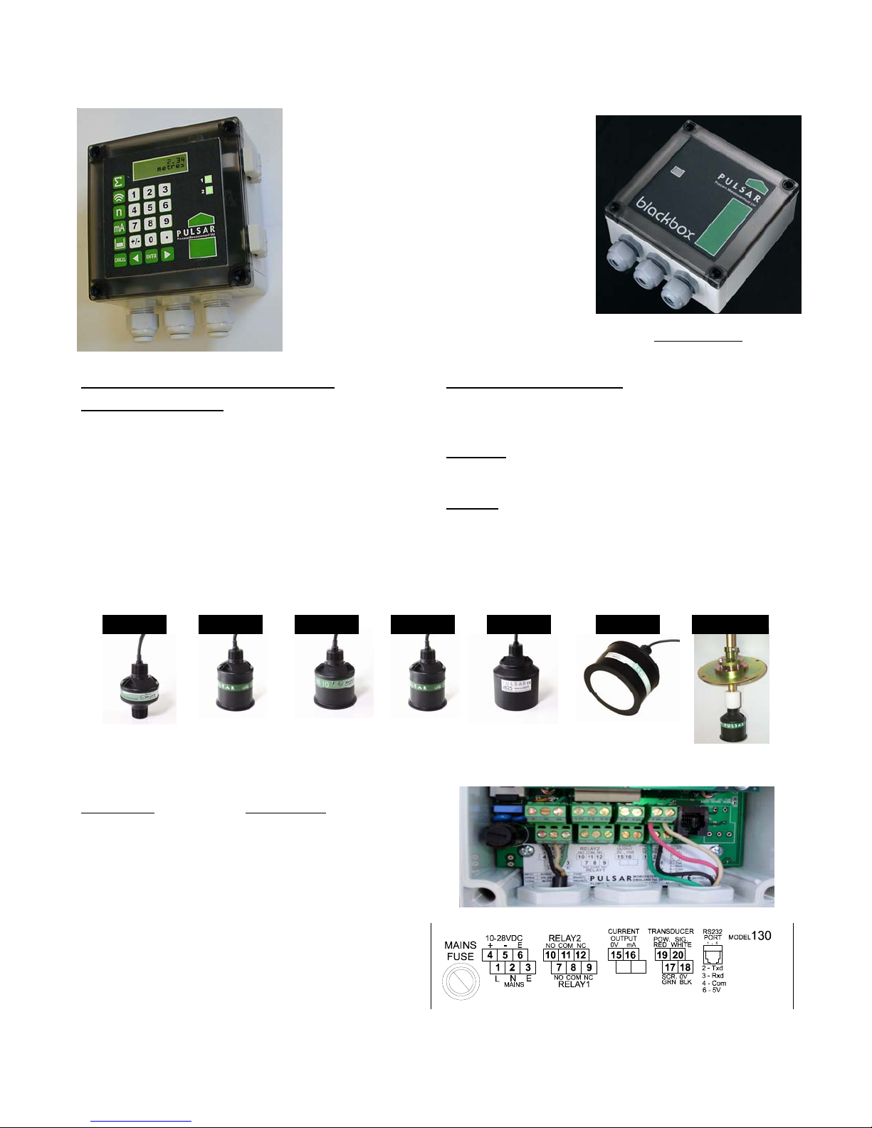
It provides non-contacting level (volume included with the keypad/display version) with 2
user-defined relays. Comes standard with
110VAC, 12VDC and 24VDC power. Options :
4-20mA, 0-5VAC, Modbus RTU, Profibus dP,
and Ethernet output versions are available.
TRANSDUCER INSTALLATION TROUBLESHOOTING
LIQUIDS and SOLIDS
• Mount the transducer away from any obstructions, falling water/solids, rough walls, pumps, switches, etc…
• Visualize looking down the echo path of the transducer
and seeing a nice clear shot (2’+ dia.) to the very bottom during fill and empty cycles.
• Ensure the maximum level does not come within the
minimum dB blanking distance.
• Confirm the inside of the standpipe is smooth and does
not have any protrusions at the weld.
• Do not hang the transducer by the cable.
• Typically, mount the dB transducer 1/2 the tank radius.
(Call Pulsar Technical Support for Special Service
Passcode and Instructions 850-609-1777.)
LIQUIDS
• Dome top tanks will require Gain & Algorithm change.
• If reading false level, use P21 and set true distance
SOLIDS
• Consult factory if the silo is extremely dusty—we can
• DATEM may map-out the true echo. Use P21 to set
• If acoustically noisy, change Algorithm to Largest.
increase the return signal strength (even during fill).
true distance and turn “Update Datem” off!
Blind Version
dB 3 dB 6 dB 10 dB 15 dB 25 dB 40 Aiming Kit
.5-10 ft 1-20 ft 1-33 ft 1.7-50 ft 2-82 ft 3-132 ft
TRANSDUCER WIRING
TERMINAL IF SPLICING
RED = POWER RED = BLACK
WHITE = SIGNAL WHITE = WHITE
BLACK & GREEN = 0V BLACK & GREEN = SHIELD
• Use any standard, 2 conductor/shielded pair for splicing (recommend 18 AWG gauge, UV protected)
• Use 16 AWG gauge if going 500 - 3,000 ft cable run.
• Transducer shield is required - do not cut or float!
• Confirm Mains Voltage Selector is set to 115VAC.
Pulsar, Inc., PO Box 799, Shalimar, FL 32579 Phone: (850) 609-1777 Fax: (850) 651-4777 support@pulsar-us.com
Page 2
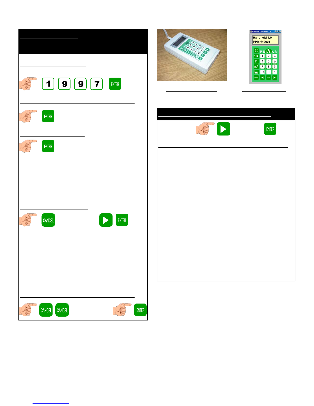
PROGRAMMING
(using either Keypad, Handheld Programmer, Handheld
Software, or Blackbox PC Software)
1. Enter Program Mode
( press and hold each button until the dash appears)
1.
Handheld Programmer Handheld Software
2. Choose “Application” (pg. 41 in manual)
3a. Choose “Operation”
“Press “ENTER” after choosing each value and confirm by
seeing “SAVED”)
Choose “Mode of Operation (P100)”
1=Distance 2=Level 3=Space
Choose “Transducer (P101)”
1=dB3 2=dB6 3=dB10 4=dB15 5=dB25 6=dB40
3b. Choose “Dimensions”
(go up a level)
Choose “Measurement Units (P104)”
1=meters 2=cm 3=mm 4=feet 5=inches
Choose “Empty Level (P105)”
(distance from face of transducer to empty level (bottom of
vessel/pump station) - automatically sets 4mA)
Choose “Span (P106)”
(distance from empty level (bottom of vessel) to 100% level
- automatically sets 20mA)
To Program a Relay (pg. 44 of the manual)
“Application” “Relays”
Choose to program Relay 1 or scroll right to Relay 2 and Enter
Choose “Relay Type” (P210, 220)
0=Not in Use 1=Alarm (will de-energize ON, de-energize OFF)
Choose “Relay Function” (P211, 221)
0=Off 1=Level 2=Temp. 3=Loss of Echo 4=Loss of Clock
Choose “Relay Alarm ID” (P212, 222)
1=General 2=High 3=HiHi 4=Low 5=LoLo 6=In Bounds
7=Out of Bounds
Choose “Relay Setpoint 1” (P213, 223)
This is the ON setpoint.
Choose “Relay Setpoint 2” (P214, 224)
This is the OFF setpoint.
Read Only “Relay Closures” (P217, 227)
This tells you how many times the relay has activated.
Choose “Relay Fail Safe” (P218, 228)
0=Default 1=Hold 2=De-Energize 3=Energize
To program Relay 2, hit “Cancel” until you see “Relay 1”. Now
scroll to the right until you see “Relay 2”. Hit Enter and start
again from the top.
To go to Run Mode, follow Step 4.
4. Calibration is done, go into Run Mode!!!
“Run Mode?”
הקינורטקלא
עב הרקבו''מ
04-8410705
Email:
ןורטגמ
1719, הפיח31016
.
ת.ד
,
ינוקרמ12
סקפ
,
sales@megatron.co.il
04-8410704
~~~~~~~~~~~~~~~~~~~~~~~~~~~~
חר'
לט.
~~~~~~~~~~~~~~~~~~~~~~~~~~~~
 Loading...