

Pulsar AWZ 710 PN-K Instruction Manual
AWZ 710
PN-K
v.1.0
Foot-operated emergency button.
EN
Edition: 3 from the 9th September 2010
Supercedes edition: 2 from the 10th July 2009
1. Technical description.
1.1 General description.
The foot-operated button is used for transmitting signal indicating alarm situation occurrence, calling help (e.g. to
the alarm central, monitoring transmitter, controller). The foot-operated button converts the signal of pressed button into a
change of the alarm status. The PN-K foot-operated button is equipped with numerous programming functions which
enable the flexible adjustment to requirements of a particular installation. The pushbutton detector is made according to
the optical technology. The output signal is presented in a form of shorting/opening contacts of reed relay switch
(noiselessly). The atni-sabotage contact is based on a microswitch with gold-covered contacts the PCB surface has been
covered with lacquer to provide protection against damp and dust. The button has got a compact casing and is equipped
with rubber anti-slip feet.
Information about types:
Model Description
AWZ 700
PN
AWZ 710
PN-K
Foot-operated emergency button.
Foot-operated emergency button, programmable.
Table 1.
Table 2.
1.2 Description of elements and connectors on PCB.
Nr
[rys.1]
[1]
[2]
[3] PROG/RESET button
[4]
[5] LED (red) operations signaling (programming)
[1] [4] Connectors descriptions
TAMP
12V
GND
RST
C
NO
Anti-sabotage switch connector
Wire holder
Supply connector and button output
NC anti-sabotage switch output
Supply output DC (12V= +U, GND)
Button reset output
NC alarm transmitter output
Element description
1
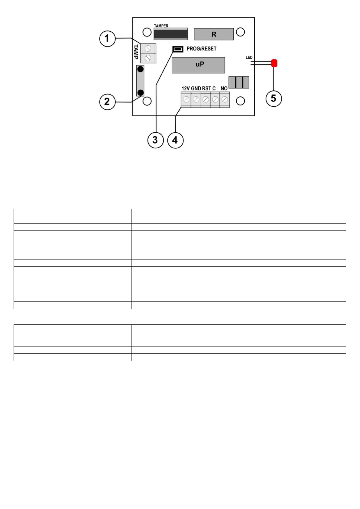
Fig. 1. The view of PCB.
1.3 Technical parameters:
- electric al parameters (tab.3)
- mechanical parameters (tab.4)
Table 3.
Supply voltage
Current consumption
ALARM transmitter
ALARM transmitter contacts
ALARM transmitter operations mode
RST output (RESET)
TMP output
Optical indication
- LED (red)
Operation conditions
Table 4.
Casing
Dimensions
Fixation
Connectors
Net/Gross weight
2. Installation.
2.1 Requirements.
The foot-operated button shall be mounted by the qualified installer having appropriate (required and necessary
for a given country) permissions and qualifications for connecting (operating) low-voltage installations. The device shall
be mounted in closed rooms, according to the environment class II, of the normal air humidity (RH=30%-90% max.
without condensation) and the temperature within the range from -10°C to +40°C.
2.2 Installation procedure.
1. Perform complete installation wiring and choose button location.
2. Open the button unscrewing two side screws (that are a button hinge).
3. Connect wire to the button through a rubber hole and block in the holder (fig.1).
4. Connect DC supply to 12V, GND holders, maintaining polarization.
5. Connect wires to ALARM (C/NO), TAMP outputs and RTS button inputs.
11V÷14V/DC (-/+5%)
17mA/30mA (R=NO/R=NC)
0,5A@30Vdc/50Vac max.
C/NC
monostable (210s max.), bistable or latch
programming function
control 0V (GND), impulse time min 1s.
C/NC, 1A@30Vdc/50Vac max.
- alarm status: permanently illuminated,
- countdown of abort time or supply restart: flashes
- programming: go to programming procedure
II environment class, -10°C ÷40°C,
metal, RAL 9003, IP20
120 x 75 x 36 (WxLxH)
No fixation
Ф0,41÷1,63 (AWG 26-14)
0,18kg/0,22kg
2
 Loading...