

Page 1

AWZ 502
v.1.2
AWZ 13,8V/5A/17Ah/LM
Linear, Buffer Power Supply Unit
EN
Edition: III (14th Feb 2012)
Supercedes the II (3rd Nov 2011) edition
Page 2

www.pulsar.pl AWZ502
2
Features:
• 13,8VDC/5A uninterruptible supply
• fitting battery: 17Ah/12V
• mains supply 230VAC
• linear voltage regulator
• battery charge and maintenance control
• battery over-discharge protection (UVP)
• battery output full protection against short-circuit
and reverse polarity connection
• jumper selectable battery charging current
0,6A/1,2A/1,8A/2,4A
• START facility for manual battery connection
• status control of the AUX1, AUX2 output fuses
• LED indication
• acoustic indication (buzzer)
• control panel - LED
• BS technical output – indicating 230V power
failure
• AW technical output of the PSU failure, tripped by:
• output short-circuit (SCP)
• output overload (OLP)
• battery disconnection <10V (UVP)
• PSU failure
• output over voltage >16,5V (OVP)
• protections:
• short-circuit SCP
• overload OLP
• overheat OHP
• over voltage OVP
• against sabotage
CONTENTS:
1. Technical description.
1.1 General description
1.2 Block diagram
1.3 Description of PSU components and connectors.
1.4 Specifications
2. Installation.
2.1 Requirements
2.2 Installation procedure
3. Operating status indication.
3.1 Control panel operation
3.2 Acoustic indication
3.3 Technical outputs
4. Operation and use.
4.1 Overload or short circuit of the PSU output
4.2 DC output over voltage protection (OVP)
4.3 Battery-assisted operation
4.4 Battery-assisted operation – standby time
4.5 Dynamic battery test
4.6 Maintenance
1. Technical description.
A buffer PSU is intended for an uninterrupted supply to alarm system devices requiring stabilized voltage of
12V/DC (+/-15%). The PSU provides voltage of 13,8V DC with current capacity:
1. Output current 5A + 0,6A battery charge
2. Output current 4,4A + 1,2A battery charge
3. Output current 3,8A + 1,8A battery charge
4. Output current 3,2A + 2,4A battery charge
Total current of the receivers + battery: 5,6A max.
In case of power decay, a battery back-up is activated immediately. The PSU is housed in a metal
enclosure (colour: RAL 9003) which can accommodate a 17Ah/12V battery. It features a micro switch that indicates
door opening (front cover) and detaching from the mounting surface.
Page 3
www.pulsar.pl AWZ502
3
OPTIONAL CONFIGURATIONS OF THE PSU:
(visualisation available at www.pulsar.pl)
1. Buffer Power Supply AWZ 13,8V/5x1A/17Ah
- AWZ502 + LB8 5x1A (AWZ579 or AWZ580) + 17Ah
2. Buffer Power Supply AWZ 13,8V/10x0,5A/17Ah
- AWZ502 + 2xLB8 10x0,5A (AWZ578 or AWZ580) + 17Ah
3. Buffer Power Supply AWZ 13,8V/16x0,3A/17Ah
- AWZ502 + 2xLB8 16x0,3A (AWZ577 or AWZ580) + 17Ah
4. Buffer Power Supply AWZ 13,8V/2x5÷7,4V/2x2A/17Ah
- AWZ502 + 2xDCDC20 (2x5÷7,4V/2x2A) + 17Ah
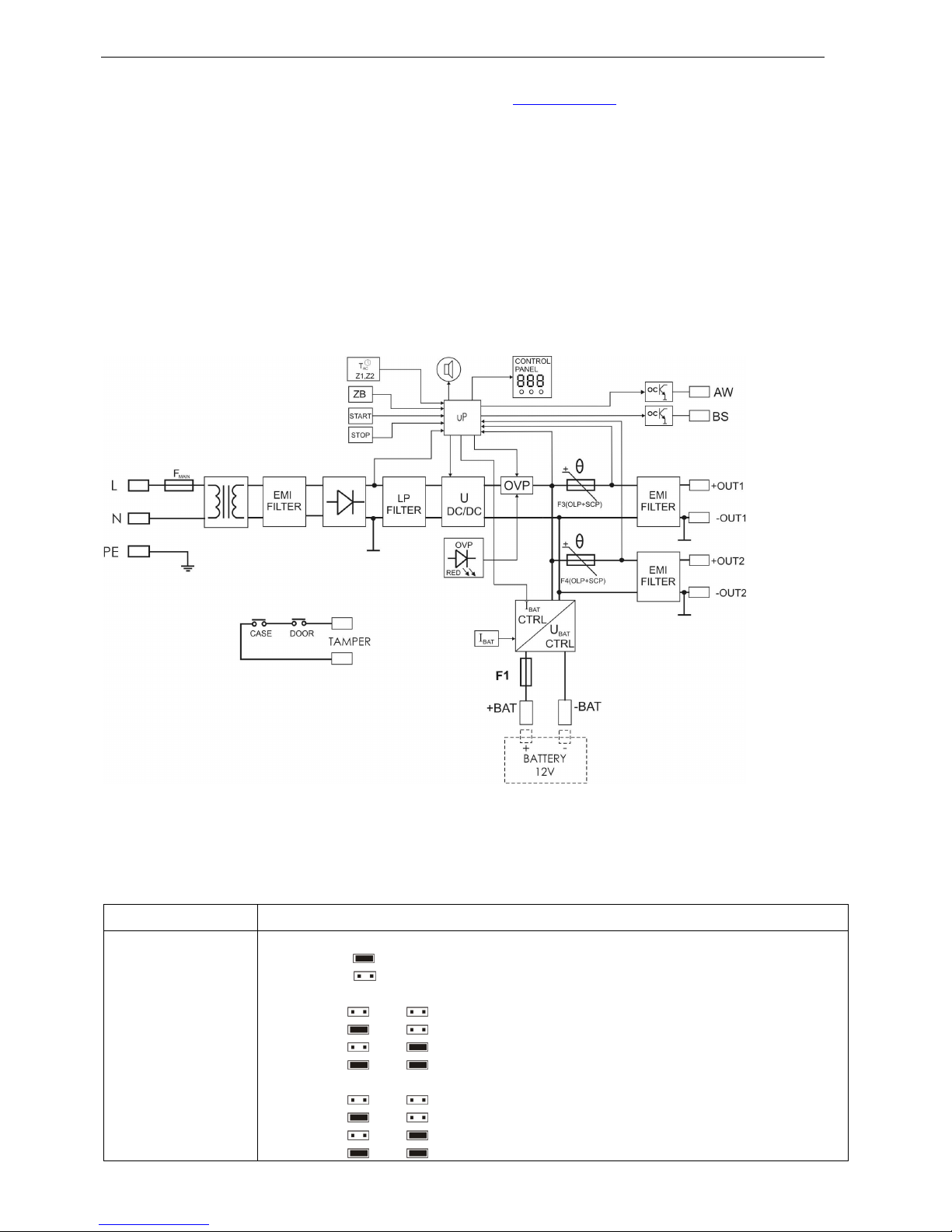
1.2 Block diagram.
Fig. 1. Block diagram of the PSU.
1.3 Description of PSU components and connectors.
Table 1. Elements of the PSU pcb (see Fig. 2).
Element nr Opis
[1]
ZB; pin acoustic indication:
• ZB = acoustic indication on
• ZB = acoustic indication off
• AKU; pins Z3;Z4 - adjustment of battery protection function UVP
• Z3= , Z4= protection on, battery disconnection time lag: 20s
• Z3= , Z4= protection on, battery disconnection time lag: 15 min
• Z3= , Z4= protection on, battery disconnection time lag: 60 min
• Z3= , Z4= protection off
AC; pins Z1, Z2 - adjustable time lag of AC power failure indication
• Z1=
, Z2= time lag T= 0s
• Z1= , Z2= time lag T= 5 min
• Z1= , Z2= time lag T= 1 h
• Z1= , Z2= time lag T= 6 h
Page 4
www.pulsar.pl AWZ502
4
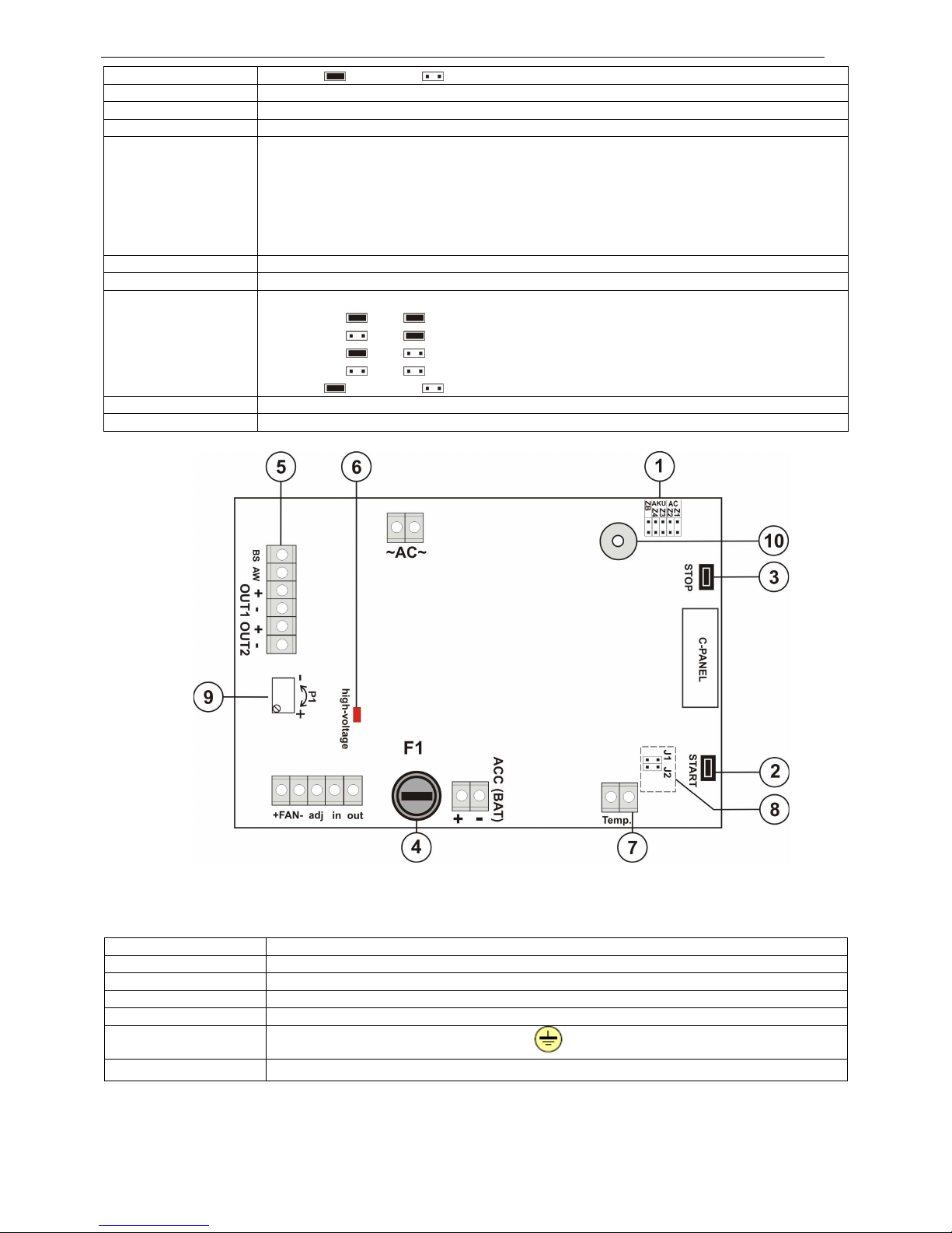
Caption: jumper on, jumper off
[2] START button (launching the PSU from a battery)
[3] STOP button (disconnection of the PSU, starting/finishing the battery test)
[4] F1 fuse in the battery circuit
[5]
Connectors:
BS - AC absence technical output – OC type (open collector)
hi-Z level = status: failure
L level = status: correct operation
AW- technical output of the PSU operation status – OC type (open collector)
hi-Z level = status: correct operation
L level = status: failure
[6]
LED indicating over voltage protection (UVP) - on
[7]
Connector of the temperature detector
[8]
J1,J2 pins- battery charging current selection
• J1= J2= Ibat =0,6 A
• J1= J2= Ibat =1,2 A
• J1= J2= Ibat =1,8 A
• J1= J2= Ibat =2,4 A
Caption: jumper on, jumper off
[9] P1 output voltage adjustment
[10]
Acoustic indicator
Fig. 2. The view of the PSU pcb.
Table 2. Elements of the PSU (see Fig. 3.)
Element no. Description
[1]
Isolation transformer
[2]
Pcb of the PSU (Tab. 1, Fig. 2)
[3] TAMPER x2 micro switches (contacts) of the sabotaże protection (NC)
[4] F
MAIN
fuse in the battery circuit (230V/AC)
[5]
L-N 230V/AC power supply connector, PE protection connector
[6]
Battery connectors +BAT = red, -BAT = black
Fig. 3. The view of the PSU.
Page 5

www.pulsar.pl AWZ502
5
Page 6

www.pulsar.pl AWZ502
6
1.4 Specifications:
- electrical specifications (tab.3)
- mechanical specifications (tab.4)
- operation safety (tab.5)
- operating specifications (tab.6)
Electrical specifications (tab. 3)
Mains supply 230V/AC (-15%/+10%)
Current consumption up to 0,55A
Power frequency 50Hz
PSU power 78W max.
Output voltage 11,0V÷13,8Vdc – buffer operation
10,0V÷13,8Vdc – battery-assisted operation
Output current
5A+ 0,6A battery charge
4,4A+ 1,2A battery charge
3,8A+ 1,8A battery charge
3,2A+ 2,4A battery charge
Output voltage setting, escalation and keeping time 500ms/150ms/110ms
Voltage adjustment range 11,0 V÷15,0 V
Ripple 20mV p-p
Current consumption by PSU systems 77 mA max.
Battery charging current 0,6A/1,2A/1,8A/2,4A przełączany za pomocą zworek J1, J2
Short-circuit protection SCP
Step I = 200% ÷ 250% of PSU power - current limitation and/or fuse
damage in the battery circuit
Step II = 110% ÷ 150% of PSU power – PCT fuse, manual restart
(disconnection of the DC output circuit)
Overload protection OLP
110% ÷ 150% @25ºC÷55ºC of PSU power – current limitation by
the PTC resettable fuse, manual restart (the fault requires
disconnection of the DC output circuit)
Over voltage protection OVP
U>16,5V disconnetion of the output voltage, automatic return
U> 14,5V fault indication
Battery circuit protection SCP and reverse polarity
connection
6,3A - current limitation, T 6,3A fuse (fuse-element replacement
required)
Over-discharge protection UVP
U<10,0 V (± 5%) – disconnection (- BAT) of the battery,
adjustment by the Z3,Z4 jumpers, time lag adjustment:
20s/15min/1h/OFF
- TAMPER - indicates enclosure opening or detaching
from the mounting surface
- 2 micro switches, NC contacts (enclosure closed),
0,5A@50V DC (max.)
Technical outputs:
- AW output indicates PSU fault:
output (SCP, OCP, OVP status);
battery (UVP, SCP status, test: negative, exceeding
the max. temperature
- BS output indicates AC power failure
- OC type, 50mA max.
normal status: level L (0V), failure: level hi-Z
- OC type, 50mA max.
normal status: level hi-Z , failure: level L (0V), adjustable time lag:
0s/5min/1h/6h
LED indication
LEDs: AC/DC power status, failure, control panel: LED display +
keypad
Acoustic indication piezoelectric indicator
F1 fuse T 6,3A
F2 fuse T 3,15 A/ 250V
Mechanical specifications (tab. 4).
Enclosure dimensions
445 x 280 x 168 (450 x 275 x 160+8) (WxHxD) ) [mm] (+/- 2)
Fixing
315 x 390, Φ 6x4szt (WxH)
Fitting battery
17Ah/12V (SLA) max.
Net/gross weight
7,20 kg / 7,70 kg
Enclosure Steel plate DC01, thickness: 1,2mm, colour: RAL 9003
Closing Cheese head screw x2 (at the front), lock assembly possible
Connectors Mains supply 230V: Φ0,63-2,05 (AWG 22-12)
OUT and BS/AW outputs: Φ0,51- 2,05 (AWG 24-12)
Battery outputs: BAT 6,3F-2,5,
TAMPER output : wires
Notes The enclosure does not adjoin the assembly surface so that
cables can be led.
PSU cooling: convectional + fan cooling (automatic)
Page 7

www.pulsar.pl AWZ502
7
Operation safety (tab.5).
Protection class PN-EN 60950-1:2007 I (first)
Degree of Protection PN-EN 60529: 2002 (U) IP20
Electrical strength of insulation:
- between input and output circuits of the PSU (I/P-O/P)
- between input circuit and PE protection circuit (I/P-FG)
- between output circuit and PE protection circuit (O/P-FG)
3000 V/AC min.
1500 V/AC min.
500 V/AC min.
Insulation resistance:
- between input circuit and output or protection circuit
100 MΩ, 500V/DC
Operating specifications (tab.6).
Operating temperature -10ºC...+40ºC
Storage temperature -20ºC...+60ºC
Relative humidity 20%...90%, without condensation
Vibrations during operation unacceptable
Impulse waves during operation unacceptable
Direct insulation unacceptable
Vibrations and impulse waves during transport PN-83/T-42106
2. Installation
2.1 Requirements
The buffer PSU is to be mounted by a qualified installer, holding relevant permits and licenses (applicable
and required for a given country) for 230V/AC and low-voltage installations. The unit should be mounted in
confined spaces, in accordance with the 2nd environmental class, with normal relative humidity (RH=90%
maximum, without condensing) and temperature from -10°C to +40°C. The PSU shall work in a vertical pos ition
that guarantees sufficient convectional air-flow through ventilating holes of the enclosure.
1. Output current 5A+ 0,6A battery charge
2. Output current 4,4A+ 1,2A battery charge
3. Output current 3,8A+ 1,8A battery charge
4. Output current 3,2A+ 2,4A battery charge
Total current of the receivers + battery: 5,6A max.
As the PSU is designed for a continuous operation and is not equipped with a power-switch, therefore an
appropriate overload protection shall be guaranteed in the power supply circuit. Moreover, the user shall be
informed about the method of unplugging (usually through assigning an appropriate fuse in the fuse-box). The
electrical system shall follow valid standards and regulations.
2.2 Installation procedure
1. Before installation, make sure that the voltage in the 230V power-supply circuit is cut off.
2. Mount the PSU in a selected location and connect the wires.
3. Connect the power cables (~230Vac) to L-N clips of the PSU. Connect the ground wire to the clip marked by the
earth symbol PE. Use a three-core cable (with a yellow and green PE protection wire) to make the connection.
Lead the cables to the appropriate clips through the insulating bushing.
The shock protection circuit shall be performed with a particular care, i.e. the yellow and
green wire coat of the power cable shall stick to one side of the terminal - marked with
‘ ‘ symbol on the PSU enclosure. Operation of the PSU without the properly made and
fully operational shock protection circuit is UNACCEPTABLE! It can cause a device
failure or an electric shock.
Page 8

www.pulsar.pl AWZ502
8
4. Connect the receivers’ cables to the +OUT1- i +OUT2 connectors of the terminal block on the PSU board. If the
output current exceeds I>2,5A, a Wheatstone bridge should be implemented at the +OUT1 i +OUT2 outputs.
If necessary, connect the device (alarm panel, controller, indicator, etc.) conductors to the technical outputs:
- BS output - indicates 230V power failure
During normal PSU operation, the BS technical output is disconnected from ground (‘-‘) and in the case of 230V AC
power loss it is connected to ground (‘-‘) after the time determined by Z1, Z2 jumpers (Tab 3).
- AW output - indicates failure
During normal PSU operation, the AW technical output is ground fault (‘-‘). If any of failures mentioned above
occurs, the output is cut off.
5. During battery-assisted operation, it is possible to determine time necessary for battery disconnection by the Z3,
Z4 pins (Tab.1) when the voltage at its terminals drops below 10.5V.
6. Determine the maximum charging current using the J1, J2 pins (Tab. 1).
7. Activate the ~230V/AC supply (the AC diode and the AUX diode should be permanently illuminated)
Check the output voltage (the PSU voltage without load should amount to 13,6 V÷ 13,9 V, during battery charge:
11,0 V÷13,8 V). If the value of the voltage requires adjustment, it should be set by the V
ADJ
potentiometer,
monitoring the voltage at the AUX output of the PSU.
8. Connect the battery in accordance with the markings (colours: “+” red, „-„ black)
9. With the STOP button, initiate or finish a dynamic battery test (Tab.1)
Deactivating the test turns out the PSU failure indication at the AW output, but it does not affect the protection
system against complete battery discharge.
10. Run a PSU test: LED indication, acoustic indication, AW technical output; through:
- cutting off the 230V AC current: LED and acoustic indications – immediately; the BS technical output –
after some time, determined by Z1, Z2 pins.
- disconnecting the battery: LED indication, acoustic indication and the AW technical output – after a
battery test have been completed (approx. 20 min.)
11. With the ZB pin, decide whether the acoustic indication stall be on. (Tab.2)
12. Check the current consumption of the receivers without exceeding the total current capacity of the PSU.
13. Erase the failure memo of the PSU.
14. Once the tests and operation control have been completed, the enclosure can be locked.
3. Operating status indication.
3.1 Control panel operation
The PSU is equipped with a panel with buttons and a 3-digit LED display. It enables reading the main voltage
and current parameters of the PSU as long as browsing failures. The panel buttons are to be used for choosing
and approving a parameter that is to be displayed.
Fig. 4. A control panel.
Page 9

www.pulsar.pl AWZ502
9
• A description of the buttons and LEDs on the PSU panel.
- scroll up /scroll down the Menu list
- approving a given entry
- switching between the parameter’s name and its nominal value
- displaying current PSU faults, pressing the button again will display the next fault
(if there are a few at the same time)
- pressing Chile browning the PSU fault will erase the fault memo
- red LED indicates a failure
- green LED indicates presence of AC power (illuminating – mains supply,
twinkling- battery-assisted operation)
Available menu entries.
FAL PSU fault memo (20 last occurrences )
Ibd battery discharge current measurement [A]
Ibc battery charge current measurement [A]
Io2 OUT2 output current measurement [A]
Io1 OUT1 output current measurement [A]
Udc current measurement at the Wheatstone bridge’s output [V]
Uo2 OUT2 output voltage measurement [V]
Uo1 OUT1 output voltage measurement [V]
Resolution for voltage measurement: 0.1V, for current measurement: 0.1A. Displayed voltage and current rate is
only approximate. For higher accuracy, a multimeter shall be used.
• Current failure overview.
In case of a failure (a red LED is illuminated on the panel), its code can be checked. After pressing the
button, a type of the failure will be displayed. If many failures occur simultaneously, pressing the again will
display the next failure code.
• Failure memo overview.
The device remembers 20 last failures in non-volatile memory. That enables subsequent overview by an
installer.
Entering the failure memo overview mode
With
choose the FAL position, approve with , a number of the failure will be displayed, then its
code. Pressing again will display the next failure in the memory.
• Erasing failure memo.
Pressing
in the failure memo overview mode will cause erasing all the stored failures.
Page 10

www.pulsar.pl AWZ502
10
• Failure codes. (tab.7)
Failure
code
Fault type Fault cause Notes
bAF
broken battery
the battery is not fully charged, the
battery is not connected,
burnt battery fuse
check the connection and the
battery fuse, read the battery
charge current
bLE
discharged battery
indicates battery voltage drop
below 10.5V
during battery-assisted
operation, the PSU will start the
countdown to the battery
disconnection
o1E
too low voltage at the
OUT1 output
Uout <9.5V
output IOUT1>3A overload
remove the cause, disconnect
the load and connect after 30 s
o2E
too low voltage at the
OUT2 output
Uout <9.5V
output IOUT2>3A overload
remove the cause, disconnect
the load and connect after 30 s
UHi
too high voltage,
indicated
Uout > 14.5V
damaged voltage regulator, wrong
setting of the P1 trimmer
potentiometer
check the setting of the P1
trimmer potentiometer
oHE
battery overheat
PSU circuits overheat, regulator
overheat, damaged temperature
detector , detector not connected
check the load balance,
ventilators, temperature
detectors’ connections, ensure
the enclosure ventilation
SEr
regulator error
over voltage protection was
activated, a break in the regulator
circuit
unplug the PSU, contact the
service center
AHE
too high supply voltage
AC >250V
check the voltage of 230V
mains supply
nAc
no voltage or too low
network voltage
Check the mains fuse of the
transformer
rSt
PSU restart
AC supply on, launching the PSU
with the START button
3.2 Acoustic indication.
Emergency situations are acoustically indicated by a buzzer. The frequency and the number of signals
depends on a fault type (Tab.8). The acoustic indication is off after removing the ZB jumper.
Tab.8
Nr Description
Situation
1
1 signal per 13s, battery-assisted
operation
no 230V AC supply
2
1 signal per 13s, mains operation battery fault
3
continuous indication failure, e.g. output overload
4
5 signals finishing the battery test
5
18 signals initiating the battery test
3.3 Technical outputs.
The PSU is equipped with indication outputs:
• BS - absence of AC supply output: - OC type output that indicates absence of AC supply. In normal
status, with 230V AC supply, the output is ground fault (L state – 0V). In case of power loss, the PSU will
switch the output into high impendence state, hi-Z, after a time period set by the Z1,Z2
jumpers (see
Tab.1).
Page 11

www.pulsar.pl AWZ502
11
• AW – technical output indicating PSU status:
the OC type output indicates the PSU failure. In normal
state (during correct operation) the output is in high
impendence state – hi-Z. In case of incorrect operating
parameters (voltage, current, temperature), the output is
ground fault (L state – 0V)
Fig.5. Electrical diagram of the OC outputs.
• TAMPER - output indicating tampering with the PSU. The output’s volt-free (potential-free) contacts
indicate PSU door status and mounting to the surface:
- unit closed and mounted: NC,
- unit opened or mounted incorrectly/detached from the mounting surface: NO
4. Operation and use.
4.1 Overload or short circuit of the PSU output
The AUX output is equipped with a protection due to a PTC polymer fuse. If the load of the PSU exceeds
I
max
(load 110% ÷ 150%
@25ºC
of the PSU power) the output voltage is automatically cut off and indicated by the
green diode going out. To restore the output power and to protect the PTC, cut off the output load for approximately
1 minute.
In the case of a short-circuit to the AUX, BAT output (load 200% ÷ 250% of the PSU power) or a reverse
polarity connection, the F1 fuse in the battery circuit becomes permanently damaged and the restoration of the
voltage at the BAT output requires replacement of the fuse.
4.2 DC output over voltage protection (OVP)
In case of voltage exceeding 16.5V±0.2V at the regulator’s output, the system cuts off the power at the
outputs to protect the battery and the receivers from damage. The outputs will be battery-powered. The protection
system is indicated by the red LED on the PSU panel. After pressing , the SEr code will be displayed.
4.3 Battery-assisted operation.
Immediate battery reverting in case of main power outage.
In order to run the PSU from the battery only, connect the BAT connectors in accordance with the signs:
+ BAT red to ‘plus’ and, - BAT black to 'minus’ then press the START button on the main board and hold
it for 5 seconds.
In order to turn off the PSU while battery-assisted operation, press the STOP button on the main board and
hold for 2 seconds. The OFF sign will appear on the display, the PSU will disconnect the output after 10 seconds.
The PSU is equipped with a discharged battery disconnection system (UVP), set by AKU: Z3, Z4
jumpers. The battery protection is active when both jumpers are on.
4.4 Battery-assisted operation – standby time
To keep the standby time, the current drawn from the PSU during batter-assisted operation should be
limited.
Characteristics for
17Ah/12V SLA
- for step 1 (8h), current Id= 1,7A
- for step 2 (15h), current Id=0,9A
QAKU = 1.25*[(Id + Iz)*Td] – basic formula
where:
QAKU - battery capacity [Ah]
1.25 - factor that allows for capacity loss due to its ageing
Id -current drawn by the receivers during inspection [A]
Iz -current drawn for PSU's own requirements [A]
Td - required inspection time [h]
4.5 Dynamic battery test
The PSU runs a battery test every 20 minutes. It is done by a momentary output voltage reduction and
voltage measurement at the battery terminals. A failure is indicated when voltage drops below
12V. Not to prolong
the loading process, the test will not be held if the battery charging current does not drop below 0.6A. The battery test
facility can be switched off if, for instance, the battery is not connected to the PSU.
Page 12

www.pulsar.pl AWZ502
12
Deactivating/activating the test: while mains supply, press the STOP button on the main board and hold it for 3
seconds. The device will confirm the activation/deactivation I the following ways: (Tab.8.)
•
testing off – the tOF sign appears on the display
• testing on –
the tON sign appears on the display
While testing (10s), the battery terminals’ voltage rate is displayed (Uba). The PSU buttons are not responsive at
that time.
Caution:
• test activation/deactivation is stored in the memory even after unplugging of the device
• test deactivation turns off the fault indication at the AW output. It does not affect the battery over-
discharge system, though.
4.6 Maintenance
Any and all maintenance operations may be performed following the disconnection of the PSU from the
power supply network. The PSU does not require performing any specific maintenance measures, however, in the
case of significant dust rate, its interior is recommended to be cleaned with compressed air. In the case of a fuse
replacement, use a replacement of the same parameters.
WEEE MARK
According to the EU WEE Directive – It is required not to dispose of electric or
electronic waste as unsorted municipal waste and to collect such WEEE separately.
The power supply unit is adapted for a sealed lead-acid battery (SLA). After the operation period it must not be disposed of but recycled
according to the applicable law.
GENERAL WARRANTY CONDITIONS
1. Pulsar K. Bogusz Sp.j. (the manufacturer) grants a two-year warranty for the equipment, starting from the initial product date
of purchase placed on the receipt.
2. If a purchase proof is missing, a three-year warranty period is counted from the device’s production date.
3. The warranty includes free-of-charge repair or replacement with an appropriate equivalent (the selection is at the
manufacturer’s discretion) if the malfunction is due to the manufacturer, includes manufacturing or material defects, unless such
defects have been reported within the warranty period (item 1 and 2).
4. The equipment subject to warranty is to be brought to the place where it was purchased, or directly to the main office of the
manufacturer.
5. The warranty applies to complete equipment, accompanied by a properly filled warranty claim with a description of the defect.
6. Should the claim be accepted, the manufacturer is obliged to provide warranty repairs, at the earliest convenience, however not
later that within 14 days from the delivery to the service centre of the manufacturer.
7. The repair period mentioned in item 6 may be prolonged, if there are no technical possibilities to carry out the repairs, or if the
equipment has been conditionally accepted, due to the breaking warranty terms by the claimant.
8. All the services rendered by force of the warranty are carried out at the service centre of the manufacturer, exclusively.
9. The warranty does not cover the defects of the equipment, resulting from:
- reasons beyond the manufacturer's control,
- mechanical damage,
- improper storage and transport,
- use that violates the operation manual or equipment’s intended use
- fortuitous events, including lightning discharges, power failures, fire, flood, high temperatures and chemical agents,
- improper installation and configuration (in defiance with the manual),
10. The warranty is void in any of the following circumstances:
- construction changes
- repairs carried out by any unauthorized service center
- damage or removal of warranty labels
- modifications of the serial number
11. The liability of the manufacturer towards the buyer is limited to the value of the equipment, determined according to the
wholesale prices suggested by the manufacturer on the day of purchase.
12. The manufacturer takes no responsibility for the defects that result from:
- the damaging, malfunctioning or inability to operate the equipment
- defects that result from using the equipment outside its stated specifications and operating parameters failing to abide by the
recommendations and requirements contained in the manual, or the use of the equipment.
Pulsar K.Bogusz Sp.j.
Siedlec 150, 32-744 Łapczyca, Poland
Tel. (+48) 14-610-19-40, Fax. (+48) 14-610-19-50
e-mail:
biuro@pulsar.pl, sales@pulsar.pl
http://
www.pulsar.pl
, www.zasilacze.pl
 Loading...