

Page 1

Model 90 Quantifier Sound Level Meter
Page 1
User Manual for the
Pulsar Model 90 Quantifier
Sound Level Meters
This manual, th e software to which it rela tes, the
program code and drawings are all:
© Copyright Pulsar Instruments Plc 1989-2012
Page 2

Model 90 Quantifier Sound Level Meter
Page 2
The content of this manua l, any illustrations, technical information and descriptions within this
document were correct at the time of going to print. Pulsar Instruments Plc reserves the right to
make any changes necessary, without notice, in line with the policy of continuing product
development and improvement.
No part of this publication may be duplicated, reprinted, stored in a data processing system or
transmitted by electronic, mechanical, photographic or other means, or recorded, translated,
edited, abridged or expanded without the prior wr itten consent of Pulsar Instruments Plc.
No liability is accepted for any inaccuracies or omissions in this manual, although due care has
been taken to ensure that is it complete and accurate as possible.
Accessories supplied by Pulsar Instruments Plc have been designed for use with the
instrumentation manufactured by Pulsar Instruments Plc. No responsibility is accepted for
damage caused by the use of any other parts or accessories.
In order to take account of a policy of continual development, Pulsar Instruments Plc reserves
the right to change any of the information contained in this publication without prior notice.
Produced by Pulsar Instruments Plc, The Evron Centre, John Street, Filey, North Yorkshire, YO14
9DQ. © Copyrig h t Pul sa r Instruments Pl c 2012
Reference Number 05/09/MODEL 90/01
Page 3

Model 90 Quantifier Sound Level Meter
Page 3
Preface ......................................................................................................................... 5
Messages and Symbols .................................................................................................. 5
Section 1 Introduction .................................................................................................. 6
Main Features ............................................................................................................... 6
Measurement Functions.................................................................................................. 6
Broadband Measurement Mode ....................................................................................... 6
1:1 & 1:3 Octave Band Measurement Mode ...................................................................... 7
Options & Accessories .................................................................................................... 7
Section 2 Getting Started ............................................................................................. 8
How to... ...................................................................................................................... 8
Make a 15 minute Broadband Measurement ................................................................................ 8
Make a 1:1 Octave Band Measur em ent over 1 minute .................................................................. 8
Make a 1:3 Octave Band Measur em ent over 5 minutes ................................................................. 8
Make a set of twenty four 1 hour m easurements .......................................................................... 8
Quick Start ................................................................................................................... 9
Switch on ................................................................................................................................ 9
Calibrate the Sound Level M eter ................................................................................................ 9
Set the measurement duration ................................................................................................. 10
Check the measurement range ................................................................................................. 10
Change the measurement function ............................................................................................ 11
Start & Stop the measu rement ................................................................................................. 11
Review the measurement ......................................................................................................... 12
Unpacking and checking the Sound Level Meter .............................................................. 13
Instruments Layout ..................................................................................................... 14
Installing the software ................................................................................................. 15
Assembly ................................................................................................................... 15
Preamplifier ............................................................................................................................ 15
Using Microphone Extension Cables ........................................................................................... 16
Batteries ................................................................................................................................ 16
Using an external power supply ................................................................................................ 17
Windshield ............................................................................................................................. 17
NK:70 Random Incidence Adaptor ............................................................................................. 17
Switching On .............................................................................................................. 18
Checking the Configuration of the Instrument ................................................................. 19
Time and Date ........................................................................................................................ 19
Measurement Range ................................................................................................................ 19
Measurement Mode ................................................................................................................. 20
Measurement Du r ation ............................................................................................................ 20
Measurement Auto Repeat ....................................................................................................... 21
Measurement Auto Synchronise ................................................................................................ 21
Configuring th e instrument from the A nalyser software................................................................ 21
Calibration .................................................................................................................. 22
Starting a measurement ............................................................................................... 23
Broadband Mode ..................................................................................................................... 23
1:1 Octave Band Mode ............................................................................................................ 23
1:3 Octave Band Mode ............................................................................................................ 24
Displaying the data during a measurement ..................................................................... 25
Broadband Mode ..................................................................................................................... 25
Pausing and Resetting a measurement ........................................................................... 26
Stopping the measurement ........................................................................................... 26
Viewing the stored measurements ................................................................................. 27
After a measurement ha s been stopped ..................................................................................... 27
Recalling stored measurements ................................................................................................ 27
Section 3 Configuring the Sound Level Meter ............................................................. 28
Keypad ...................................................................................................................... 28
Menu System .............................................................................................................. 28
Measurement Mode ..................................................................................................... 29
Broadband Mode ..................................................................................................................... 29
1:1 Octave Band Mode ............................................................................................................ 30
Page 4

Model 90 Quantifier Sound Level Meter
Page 4
1:3 Octave Band Mode ............................................................................................................ 30
Measurement Duration ................................................................................................. 31
Measurement Auto Repeat ............................................................................................ 33
Measurement Auto Synchronise .................................................................................... 34
Measurement Range .................................................................................................... 35
Instrument Setup ........................................................................................................ 37
Display Contrast ..................................................................................................................... 37
Time & Date ........................................................................................................................... 38
Calibration Level ..................................................................................................................... 38
Display Resolution ................................................................................................................... 39
Time Weighting ...................................................................................................................... 40
Frequency Weighting ............................................................................................................... 40
Ln values ............................................................................................................................... 41
User Metric ............................................................................................................................ 42
Configuring th e instrument from the A nalyser software................................................................ 43
Section 4 Viewing and Downloading the measurements ............................................. 44
Recalling Stored Measurements ..................................................................................... 44
Broadband Measurement ......................................................................................................... 45
1:1 Octave Band Measurements ............................................................................................... 45
1:3 Octave Band Measurements ............................................................................................... 46
Checking & Clearing the memory ................................................................................... 48
Downloading Measurements to the Software ................................................................... 50
Software Insta l lation .................................................................................................... 50
Connecting the instrument to the PC .............................................................................. 50
Understanding how the measurements are stored ........................................................... 51
Section 5 Maintenance & Care .................................................................................... 53
Section 6 Troubleshooting .......................................................................................... 54
Basics ........................................................................................................................ 54
Calibration .................................................................................................................. 54
Measurements & Settings ............................................................................................. 54
Downloading Measurements ......................................................................................... 55
Appendix 1 Specifications ........................................................................................... 56
Model 105 & 106 Acoustic Calibrators ........................................................................ 61
Operation. .................................................................................................................. 61
Switching on the Calibrator ...................................................................................................... 61
Permanent-on Mode ................................................................................................................ 61
Calibrating a Sound Level Meter. ............................................................................................... 62
Background Noise ................................................................................................................... 62
Stabilisation ........................................................................................................................... 62
Changing the Battery ................................................................................................... 63
Battery type. .......................................................................................................................... 63
Specification. .............................................................................................................. 64
Technical Informa t io n .................................................................................................. 65
Free Field Correction .................................................................................................... 66
Microphone Correction Values ................................................................................................... 66
Example ................................................................................................................................ 66
Appendix 3 Software Installation ............................................................................... 67
System Requirements .................................................................................................. 67
Installation Requirements ............................................................................................. 67
Appendix 4 Configuring the instrument from the software ......................................... 68
Appendix 5 CE Certificate of Conform ity ..................................................................... 69
Equipment Description ................................................................................................. 69
Guarantee................................................................................................................... 70
Pulsar Instruments Offices ............................................................................................ 70
Page 5

Model 90 Quantifier Sound Level Meter
Page 5
Preface
Thank you for purchasing this MODEL 90 Series Sound Level Meter from Pulsar
Instruments Plc. This powerful instrument provides excellent expansion capability, and
has been designed to provide reliable, accurate measurements over a long period of
time.
This manual describes the procedure that should be followed to set up and operate the
MODEL 90 Sound Level Meter, as well as comprehensive technical information, using
optional accessories as well as troubleshooting.
This manual also contains the information regarding the MODEL 106 and MODEL 105
Acoustic Calibrators.
If you are a new user of Sou n d L evel Meters or new to the MODEL 90 Sound Level
Meter, first read Section 1 Introduction to familiarise yourself with the features,
components and accessories supplied. Then read Section 2 Getting Started for step-bystep instructions on how to use the instrument.
The different versions of the MODEL 90 are:
MODEL 91 Class 1 Broadband Only
MODEL 92 Class 2 Broadband Only
MODEL 93 Class 1 Broadband with 1:1 Octave Band Filters
MODEL 94 Class 2 Broadband with 1:1 Octave Band Filters
MODEL 95 Class 1 Broadband with 1:1 & 1:3 Octave Band Filters
MODEL 96 Class 2 Broadband with 1:1 & 1:3 Octave Band Filters
The MODEL 90 Sound Level Meters meet the requirements for Class 1 and Class 2 of
IEC 61672-1:2002 standard for Class 1 Group X or Class 2 Group X Sound Level Meters
as appropriate.
They also meet the requirements for Class 1 and Class 2 according to IEC 60651 and
60804 depending upon the version of the instrument. Please refer to page 56 for full
technical details of the MODEL 90 Sound Level Meters.
To meet the requirements of ANSI S1.4 for Rand om Incidence microphone response, an
NK:70 Random Incidence Adaptor should be used when making measurements. Please
refer to page 17 for details of the use of the NK:70 Random Incidence Adaptor.
Messages and Symbols
Messages are used in this manual to bring important information to your attention. The
different message types are indicated as shown below.
Pay attention! A caution informs you that improper use of the equipment or
failure to follow instructions may cause data loss or may damage the
equipment.
Page 6
Model 90 Quantifier Sound Level Meter
Page 6
Please read. A note is a hint or advice that helps you make best use of the
equipment and accessories.
Section 1 Introduction
Main Features
Measurement Functions
The measurement functions that can be provided by the MODEL 90 depend upon the
options that have been fitted. If the instrument has been fitted with the 1:1 Octave
Band or the 1:3 Octave Band filters, these measurements will be available.
Listed below is a summary of the measurements that can be provided by the basic
Broadband instrument, and by the addition of the 1:1 Octave Band or the 1:3 Octave
Band filters.
If the Auto Repeat function is used, the MODEL 90 can be made to repeat the
broadband measurement up to 999 times. See page 21 for details of setting the auto
repeat function. The instrument can also be configured to synchronise the
measurement start time with the instrument clock. See page 21 for details of the Auto
Synchronise function.
Broadband Measurement Mode
In Broadband Mode, the instrument stored the overall values such as L
Aeq
, L
AFmax
and
Ln’s as well as storing a noise profile, or Time History, during each measurement.
The MODEL 90 instruments can store up to 1,300 Broadband Measurements which can
be of any length, up to a maximum of 99 hours per measurement. With each
measurement is stored a noise profile which consists of 1 second Leq samples, with up
to a maximum of 11 days of Noise Profile being available.
Function
Frequency
Weighting
Displayed as
Maximum
value
Minimum
value
Sound Level with Fast Time
Weighting
A
LAF
L
AFmax
L
AFmin
C
LCF
L
CFmax
L
CFmin
Z
LZF
L
ZFmax
L
Zfmin
Sound Level with Slow Time
Weighting
A
LAS
L
ASmax
L
ASmin
C
LCS
L
CSmax
L
CSmin
Z
LZS
L
ZSmax
L
Zsmin
Sound Level with Impulse
Time Weighting
A
LAI
L
AImax
L
AImin
C
LCI
L
CImax
L
CImin
Z
LZI
L
ZImax
L
ZImin
Equivalent Continuous Sound
Pressure Level with
integration time t
A
L
Aeqt
- -
C
L
Ceqt
- -
Z
L
Zeqt
- -
Sound Exposure Level (SEL)
A
LAE - -
C
LCE - - Z LZE - -
Peak Sound Pressure
C
LCpeak
-
-
Takt Maximum Sound Level
DIN 45641 (L
AFTeq
)
A LAFTeq - -
Impulse Weighted Equivalent
A
LAIeqt
-
-
i
Page 7
Model 90 Quantifier Sound Level Meter
Page 7
Sounds Press Level with
integration time t (L
Ieqt
)
C
LCIeqt
-
-
Z
LZIeqt
-
-
Please note that only one Frequency Weighting can be selected at any time.
1:1 & 1:3 Octave Band Measurement Mode
In the 1:1 or 1:3 Octave Band Filter Mode, the MODEL 90 instrument provide a
sequential sweep through the filter bands over the measurement duration. In addition
to the frequency bands, the instruments also provide a measurement of the overall
L
Aeq
, L
Ceq
and L
Zeq
functions.
Function
Frequency
Weighting
Displayed as
Stored
Measurement
Applies to
Sound Level with Fast Time
Weighting
Z LZF No
1:1 & 1:3
Octave Bands
Equivalent Continuous Sound
Pressure Level with
integration time t
Z LZeqt Yes
1:1 & 1:3
Octave Bands
A
LAeqt
Yes
Broadband
C
LCeqt
Yes
Broadband
Z
LZeqt
Yes
Broadband
The 1:1 Octave Band Filters cover the following frequency bands: 31.5Hz to 16kHz
The 1:3 Octave Band Filters cover the following frequency bands: 25Hz to 16kHz
When the MO:800/6 Options is fitted, the 1:3 Octave Band Filters include the additional
20Hz and 20kHz 1:3 Octave Band Filters.
Options & Accessories
The MODEL 90 Series are also available with a range of options and accessories that
can enhance the performance and applications of the instrument. For full details, please
contact Pulsar Instruments Plc your local representative.
The most commonly used accessories are listed below.
Model 105 Class 1 Acoustic Calibrator
Model 106 Class 2 Acoustic Calibrator
K2 Hard Attache Case
WS90 Windshield
CP1 Carry Pouch
TR1 Tripod
DC80 USB Download Cable
MEC2 2 m Microphone Extension Cable for Instruments with removable preamp
MEC 5 5 m Microphone Extension Cable for Instruments with removable preamp
MEC10 10 m Microphone Extension Cable for Instruments with removable preamp
TM1 Preamplifier Tripod Mount
Outdoor Kits
WK1 Outdoor Weatherproof Kit with Lightweight Outdoor Microphone System
WK2 Outdoor Weatherproof Kit with Heavy Duty Outdoor Microphone System
Replacement Microphone Capsules
Page 8

Model 90 Quantifier Sound Level Meter
Page 8
MK:226 Class 1 Microphone Capsule for Models 91, 93 & 95
MK:216 Class 2 Microphone Capsule for Models 92,94 & 96
Section 2 Getting Started
How to...
These example settings are designed to demonstrate the different configurations that
are available from the MODEL 90 Sound Level Meters. Please check the configuration of
the instrument to match the measurement requirements of your application before
making a measurement.
Make a 15 minute Broadband Measurement
1. Switch on
2. Calibrate
3. Set Measurement Mode to Broadband
4. Set measurement duration to 15 minutes
5. Switch off Auto Repeat & Auto Synchronise
6. Set Measurement Range
7. Start Measurement
a. Run for 15 minutes
8. Stop Measurement
9. Review Measurement Data
Make a 1:1 Octave Band Measurement over 1 minute
1. Switch on
2. Calibrate
3. Set Measurement Mode to 1:1 Octave Band
4. Set Measurement Duration to 1 minute
5. Set Measurement Range
6. Start Measurement
a. Run for 1 minute
7. Stop Measurement
8. Review Measurement Data
Make a 1:3 Octave Band Measurement over 5 minutes
1. Switch on
2. Calibrate
3. Set Measurement Mode to 1:3 Octave Band
4. Set Measurement Duration to 5 minutes
5. Set Measurement Range
6. Start Measurement
a. Run for 5 minutes
7. Stop Measurement
8. Review Measurement Data
Make a set of twenty four 1 hour measurements
1. Switch on
2. Calibrate
3. Set Measurement Mode to Broadband
4. Set Measurement Duration to 1 hour
5. Set Auto Repeat to On
6. Set Number to 25
7. Set Auto Synchronise to On
a. Start Measurement
Page 9
Model 90 Quantifier Sound Level Meter
Page 9
8. After 24 1 hour measurements the instrument will stop
9. Review Measurement Data
Quick Start
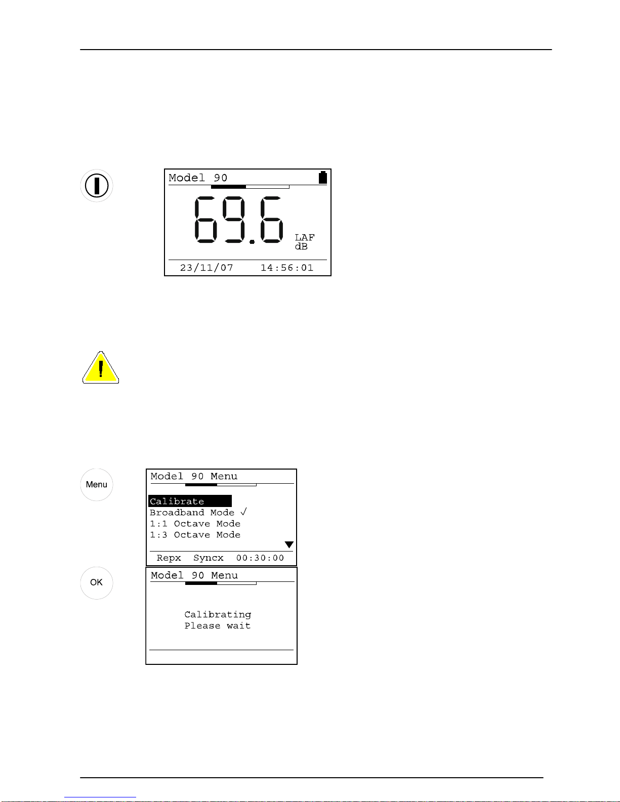
Switch on
Key Press Display
When the instrument has switched on, the start-up screen will change to the standard
noise le v el disp la y .
Calibrate the Sound Level Meter
If a microphone extension cable is to be used during a measurement, the
instrument must be calibrated with the cable attached.
Connect the Acoustic Calibrator to the Sound Level Meter and select the 94dB setting
on the Acoustic Calibrator. Press the Menu key to select the Calibrate option and press
OK to start the calibration procedure.
Key Press
Display
Comments
Page 10
Model 90 Quantifier Sound Level Meter
Page 10
If the calibration is successful , p ress the exit key to return to the main screen.
Set the measurement duration
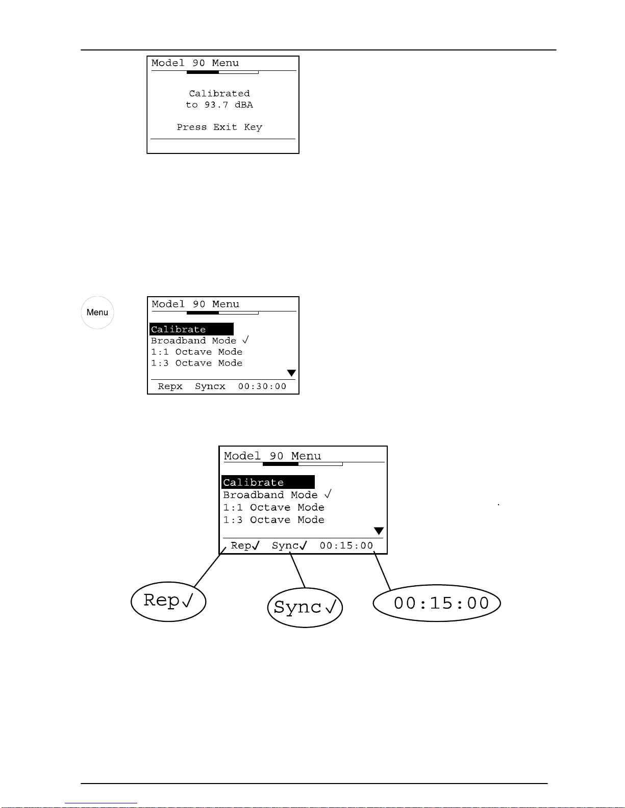
Press the menu key to view the current measurement duration and the status of the
auto repeat and auto synchronise function. At the bottom of the screen is the current
configuration.
Key Press
Display
Comments
In this example, the measurement
duration is set to 30 minutes.
The Auto-Repeat function is
switched on.
The Auto-Synchronise function is
switched on.
If the measurement duration is not as required, use the Measurement Duration menu
option to set the required measurement duration. Refer to page 31 for details of setting
the measurement duration.
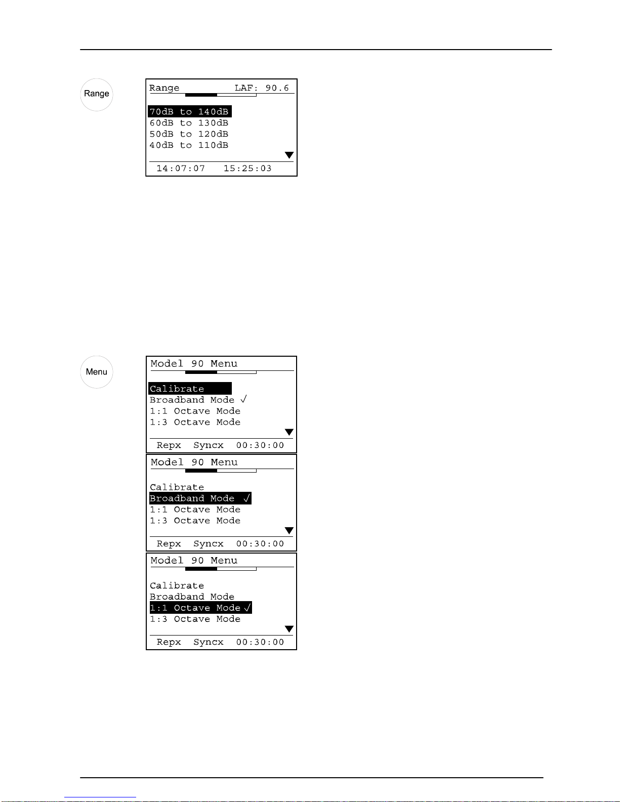
Check the measurement range
Press the Range key to check the current measurement range.
Page 11
Model 90 Quantifier Sound Level Meter
Page 11
Key Press
Display
Comments
In this example, the measurement
range is set to 70dB to 140dB.
To change the measurement range, use the Up and Down Arrow keys to select the
required measurement range and press OK. Refer to page 35 for details of setting the
measurement range and the use of the bar graph display in choosing the correct
measurement range.
Change the measurement function
To check the current measurement function and to change the measurement function,
press the menu key. Use the Up and Down arrows keys to select the required
measurement mode and OK to Select the mode required.
Key Press
Display
Comments
In this example, the instrument is
set to Broadband Measurement
Mode
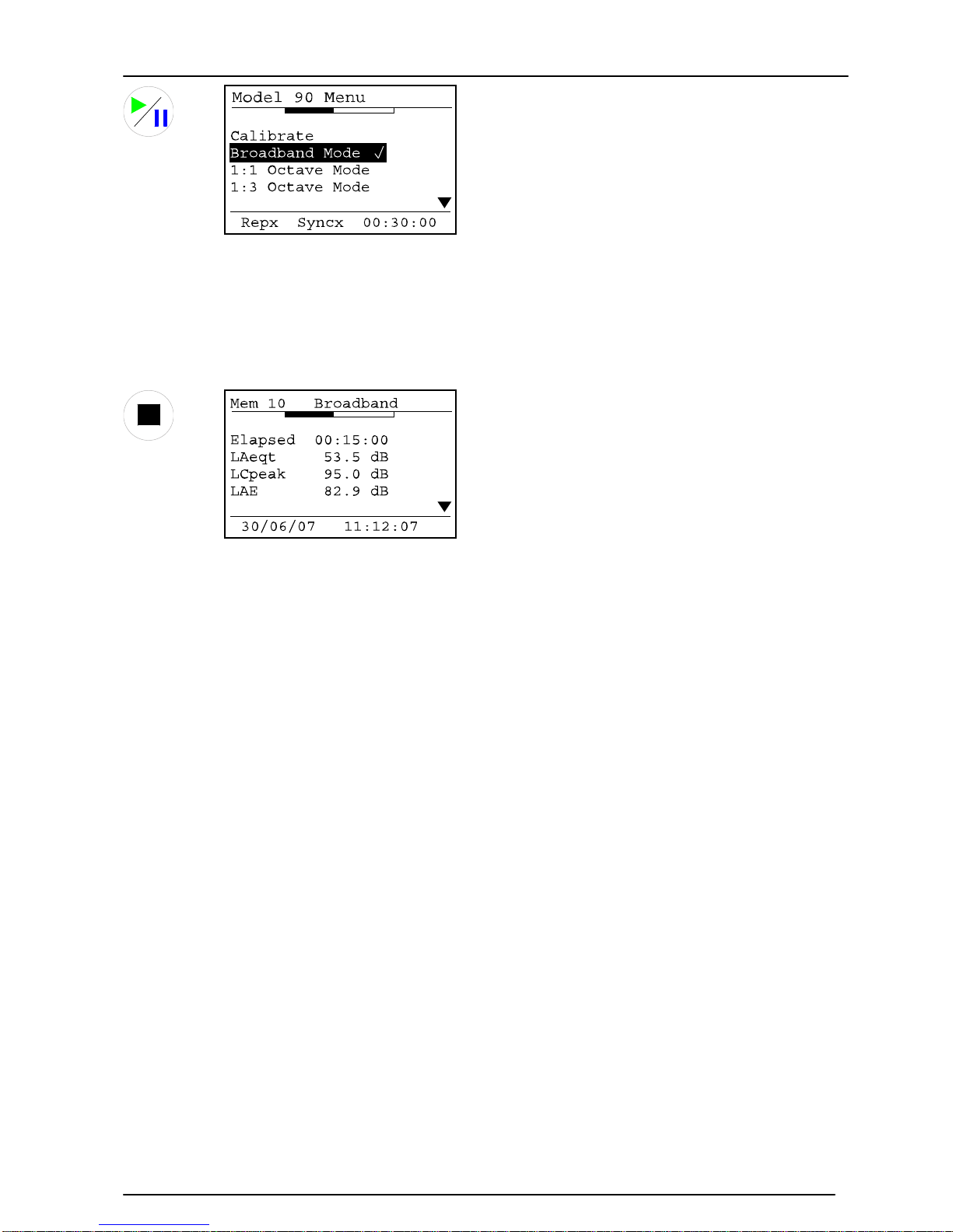
Start & Stop the measurement
To start the measurement, press the Start Key
Key Press
Display
Comments
Page 12
Model 90 Quantifier Sound Level Meter
Page 12
Press the Up and Down arrow keys to view the measurement functions during the
measurement.
To stop the measurement, press the Stop Key.
Key Press Display
Comments
The instrument stores the
measurement in memory and
enters the measurement review
mode.
Review the measurement
When the measurement has been stopped, the instrument automatically stores the
measurement in memory and enters the measurement review mode. Use the Up and
Down arrow keys to view the different measurement values and press the exit key to
return to the main display.
Refer to page 44 for details of the measurement review mode.
Page 13

Model 90 Quantifier Sound Level Meter
Page 13
Unpacking and checking the Sound Level Meter
Carefully remove the instrument from its shipping container and inspect it for possible
damage or missing items. If the meter appears to be damaged or something is missing,
contact Pulsar Instruments Plc your local re pres e ntative immediately.
The basic MODEL 90 instrument is supplied with the following standard accessories:
Analyser for Windows Software on CD-ROM
MODEL 90 User Manual
Certificates of Calibration
ZL:100 USB Data Cable
Batteries 2 x AA
In addition, the Class 1 versions of the instrument are supplied with an MV:200D
Preamplifier and a microphone box.
If you have ordered the instrument as a complete measurement kit, you will have also
received some further items such as an Acoustic Calibrator, Carrying Case and
Windshield.
Page 14
Model 90 Quantifier Sound Level Meter
Page 14
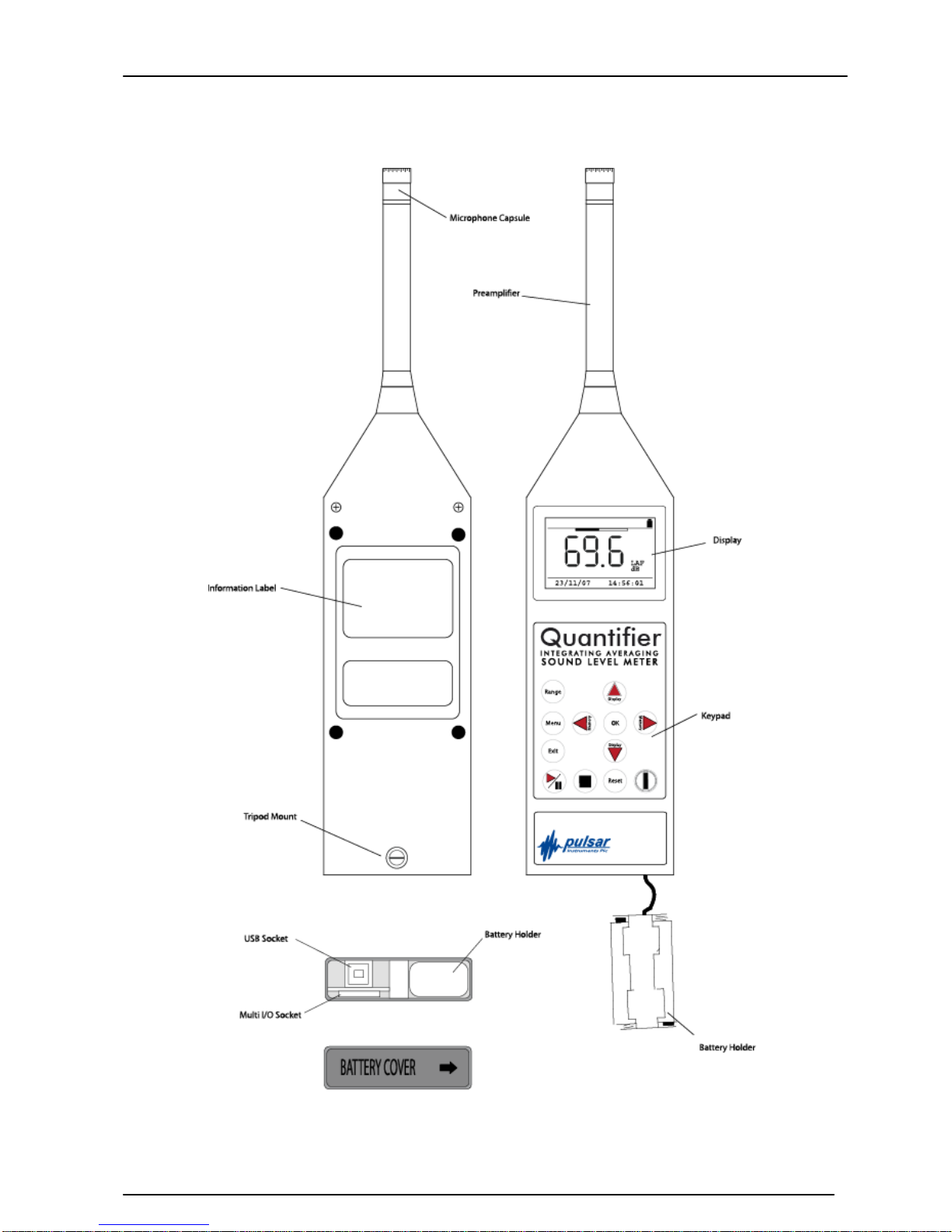
Instruments Layout
Page 15
Model 90 Quantifier Sound Level Meter
Page 15
Installing the software
Before measurements can be downloaded from the MODEL 90 instrument, the Analyser
software must be installed from the supplied CD.
Please refer to page 50 for further details of the installation of the Analyser software.
Assembly
The MODEL 90 instruments are supplied fully assembled apart from the MV:200
Preamplifier for Class 1 instruments and the batteries.
Preamplifier
The Class 1 versions of the MODEL 90 (MODEL 91, MODEL 93 and MODEL 95) are
supplied with a removable preamplifier, the MV:200D. Also, a removable preamplifier
may be fitted as an option to the Class 2 instruments.
This preamplifier must be connected to the Sound Level Meter before the unit is
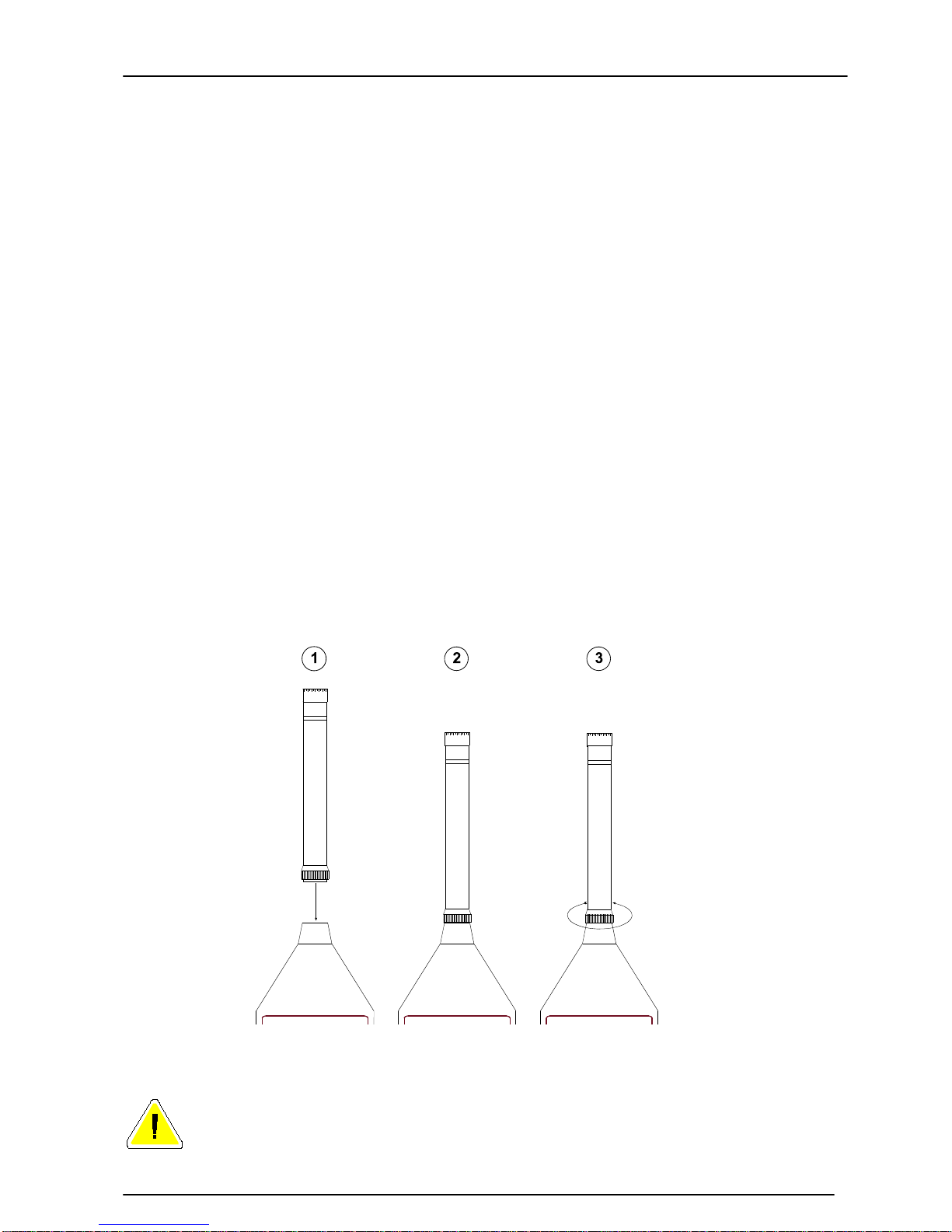
switched on. This unit is connected to the top of the MODEL 90 using a locking ring. To
connect the MV:200D Preamplifier, follow the diagram below:
(1) Place the preamplifier into the s ocket on the Sound Level Met er
(2) Ensure the connector has located into the socket
(3) Tighten the Locking Ring.
Do not cross thread the locking ring. Damage caused by misuse is not covered by the
warranty for the instrument.
Removing the Preamplifier
Do not twist the preamplifier body. Unscrew the locking ring and pull the
Page 16
Model 90 Quantifier Sound Level Meter
Page 16
preamplifier from the Sound Level Meter .
Using Microphone Extension Cables
The MODEL 90 instruments can be used with a microphone extension cable if the
instrument is fitted with the removable preamplifier. If a microphone extension cable is
to be used during a measurement, the instrument must be calibrated with the cable
attached.
Connect the microphone extension cable in the same manner as the MV:200C
Preamplifier.
Batteries
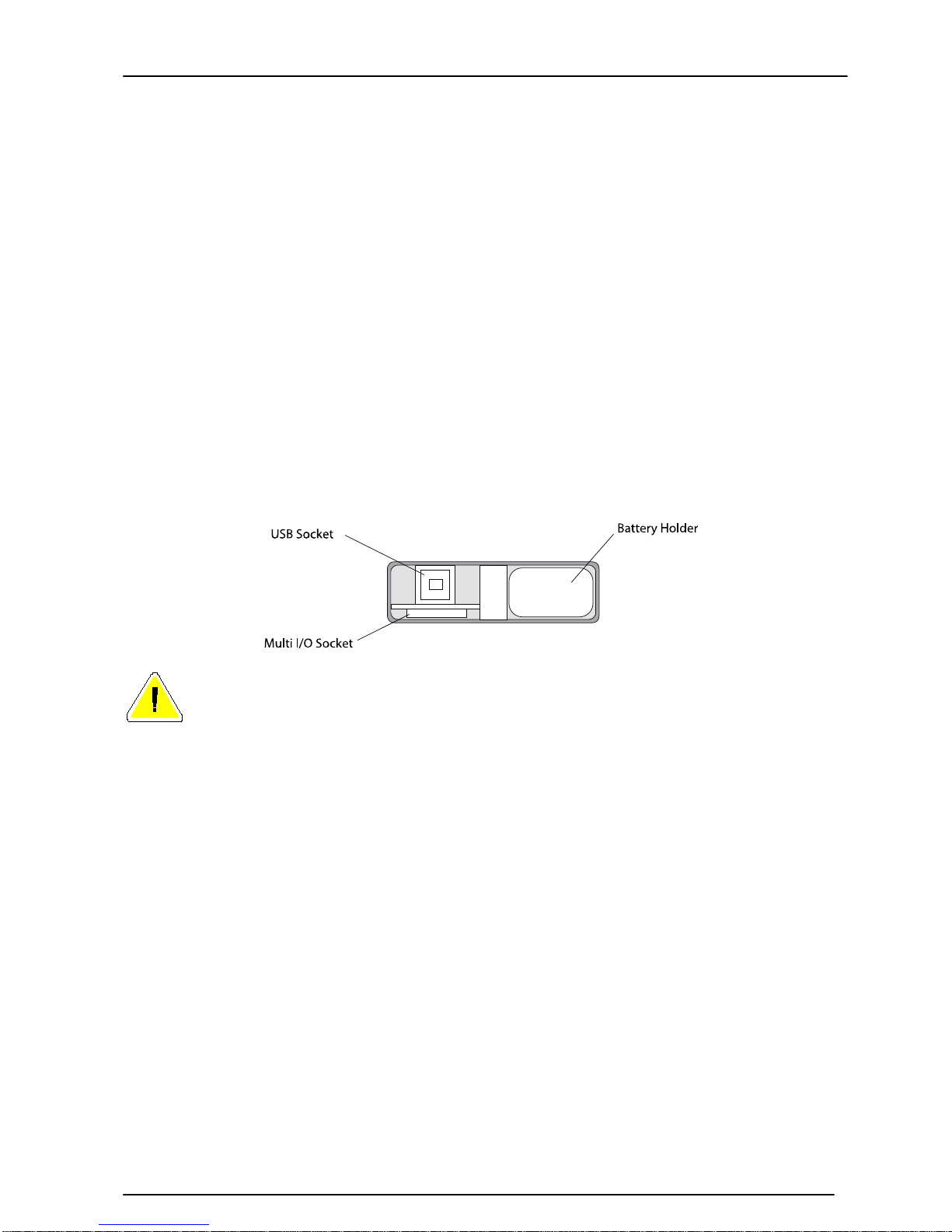
The batteries of the MODEL 90 are located behind the cover on the bottom of the
instrument. Slide the cover to the right hand side to remove and to access the battery
holder.
Ensure the instrument is switched off. Remove the battery holder from the instrument
and insert the batteries. The MODEL 90 instruments uses two AA type batteries, also
known as LR6.
Ensure that the batteries are inserted correctly. DO NOT reverse the polarity
of the batteries as this may cause damage to the instrument.
Page 17
Model 90 Quantifier Sound Level Meter
Page 17
Using an external power supply
The MODEL 90 can be used with an
external power supply. When the
external supply is connected, the MODEL
90 switches automatically from the
internal battery power.
When the external power is either
removed or switched off, the instrument
will automatically switch back to the
internal battery supply.
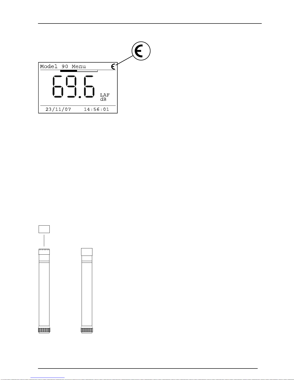
When an external supply is connected, the display of the instrument will show a symbol
in the top right corner as shown below.
Windshield
The MODEL 90 Series can be used with a 90mm Foam Windshield which will reduce the
noise levels generated by air turbulence over the microphone capsule.
The windshield can also be used to protect the microphone capsule of the Sound Level
Meter from dust and fluids which may affect the performance of the instrument. To use
the Windshield, push the hole in the windshield over the microphone of the Sound Level
Meter. The Windshiel d must be removed befor e t h e Sound Level Meter can be
calibrated.
NK:70 Random Incidence Adaptor
The NK:70 Random Incidence Adaptor is designed to modify the
response of the microp h one capsule from Free Field to Random
Incidence in order to comply with the requirements of ANSI
S1.4.
For instruments supplied for use outside of the USA, this
adaptor may not be supplied. For further details, please contact
your local representative.
To fit the NK:70 Random In cidence Adaptor, push the adaptor
over the microphone grill. Do not attempt to remove the
microphone grill as this may cause damage to the capsule.
To calibrate the instrument fitted with the microphone capsule,
remove the NK:70 Adaptor and follow the instructions supplied
with the instrument. Do Not attempt to calibrate the instrument
with the NK:70 fitted.
Page 18
Model 90 Quantifier Sound Level Meter
Page 18
Switching On
Key Press
Display
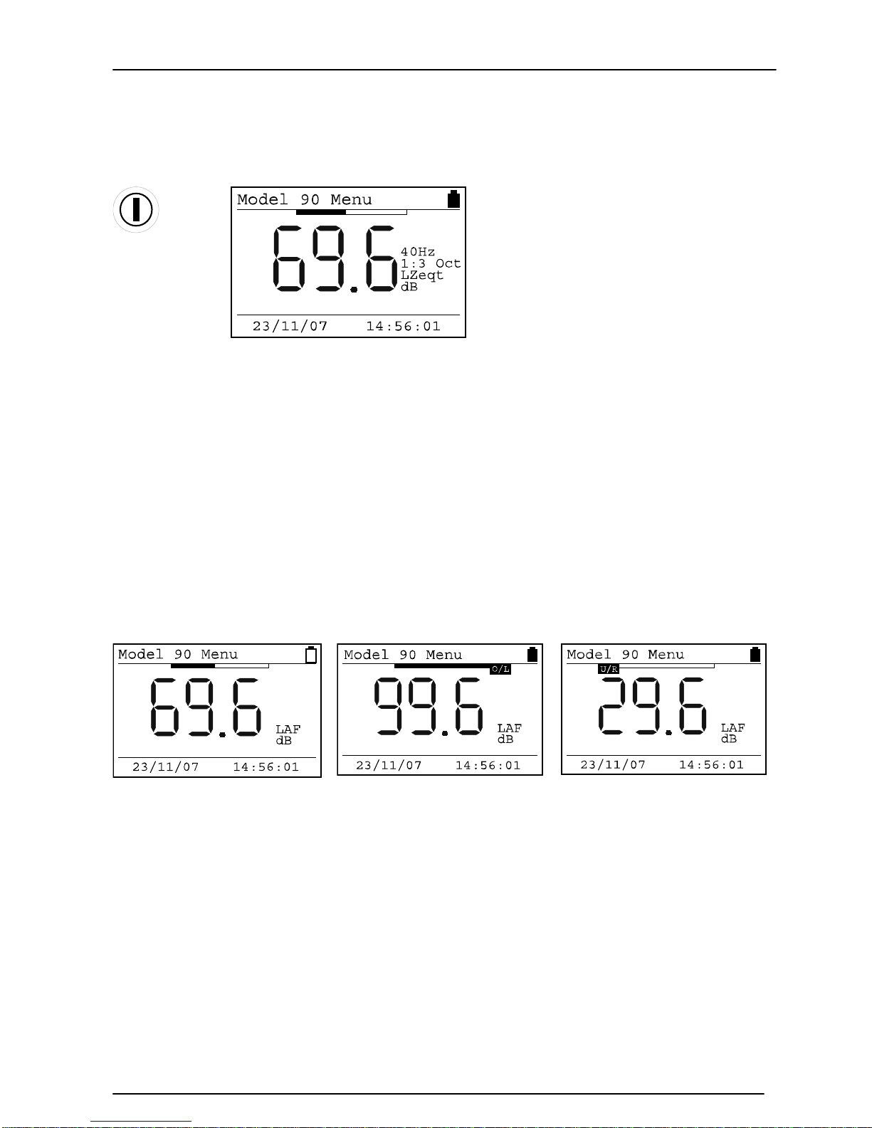
When the instrument is first switched on, a Welcome screen is shown with the
instrument type and version number. After 3 seconds, the display will change and the
current Sound Level will be shown with the current configuration shown as above.
In this example, the instrument is showing the Fast A-Weighted Sound Level with the
current Date and Time shown at the bottom of the screen. The battery level is shown in
the top right hand corner of the display.
Across the top of the display, above the numbers, is shown the sound level as a bar
graph. This graph is scaled with the current measurement range. Please refer to page
35 for details of changing the measurement range.
The display will also show the battery level and when the instrument is in Overload or
Under Range. The Glossary on page Error! Bookmark not defined. also describes the
indication of Overload and Under Range.
Low Battery Level
Overload
Under Range
Page 19
Model 90 Quantifier Sound Level Meter
Page 19
Checking the Configuration of the Instrument
The Setup of the instrument should be checked before making a measurement.
Time and Date
Key Press
Display
Comments
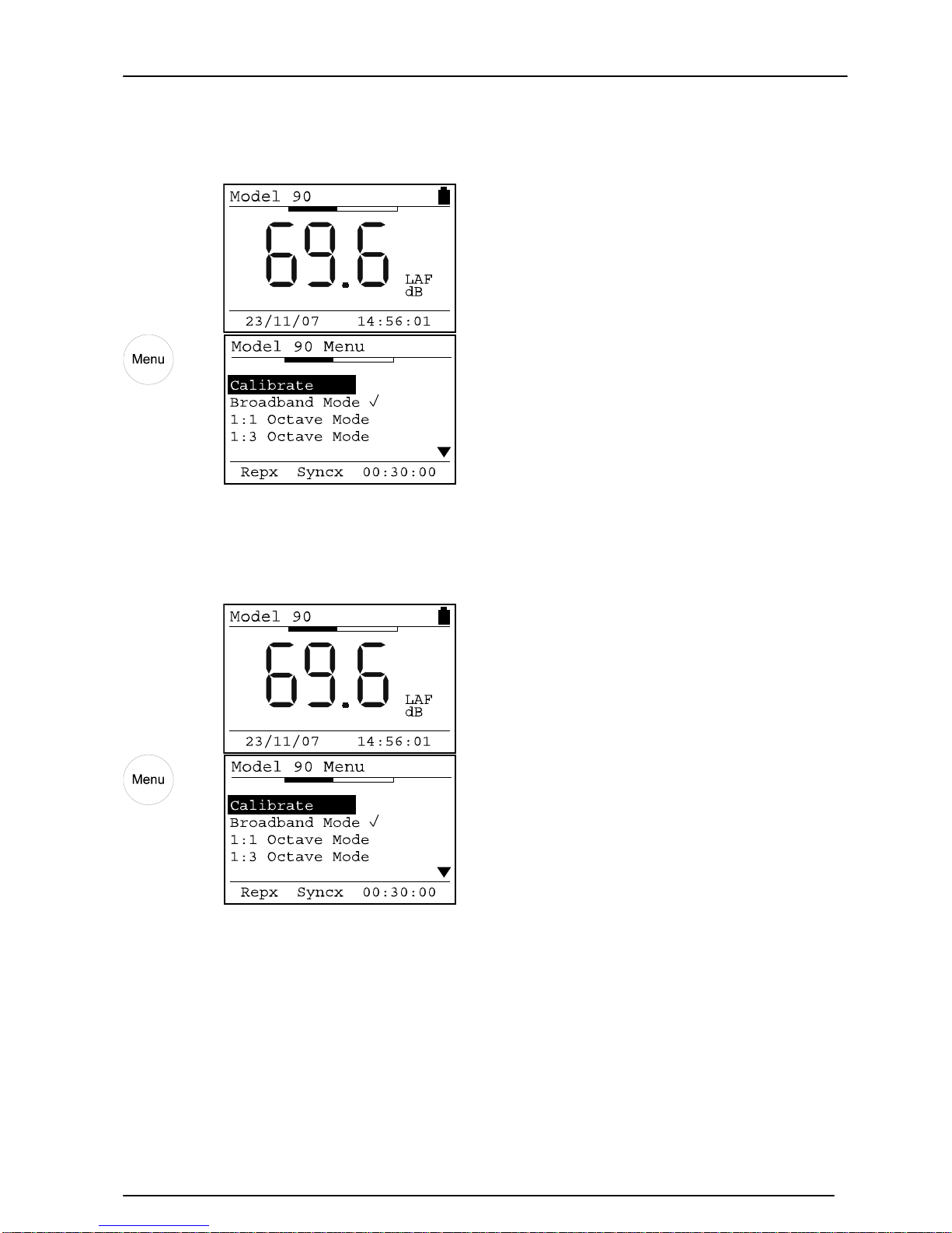
The current time and date are
shown at the bottom of the
screen.
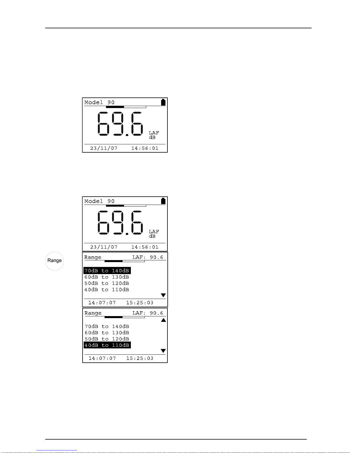
Measurement Range
Key Press
Display
Comments
The current measurement range is
shown highlighted. Use the Up
and Down Arrows to change the
range.
Press the OK key to change the
range or Exit to discard.
The bar at the top of the screen
shows the noise level in proportion
to the measurement range.
Page 20
Model 90 Quantifier Sound Level Meter
Page 20
Measurement Mode
Key Press
Display
Comments
The current measurement mode is
shown on the screen.
In this example, the measurement
mode is Broadband.
Measurement Duration
Key Press
Display
Comments
The measurement duration is
shown at the bottom of the
screen.
In this example, the measurement
time is 30 minutes.
When the instrument is set to either 1:1 or 1:3 Octave Band Mode, the Run Duration is
divided between the frequency bands. For example, if the measurement duration is set
to 30 minutes, the MODEL 90 instrument will take a total of 30 minutes to complete
the sweep through the frequency bands.
To meet the accuracy required by the standards to which the instrument is designed to
meet, there is a minimum time required to measure each frequency band. Therefore,
the MODEL 90 enforces a minimum measurement duration of 1 minute for the 1:1
Octave Band Mode and 3 minutes for the 1:3 Octave Band Mode.
Page 21
Model 90 Quantifier Sound Level Meter
Page 21
Measurement Auto Repeat
Key Press
Display
Comments
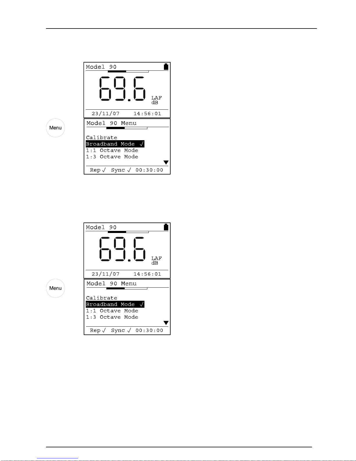
The status of the Auto Repeat is
shown at the bottom of the
screen.
In this example, the Auto Repeat
is switched on.
When the Auto Repeat is switched
off, the display is Repx
Measurement Auto Synchronise
Key Press
Display
Comments
The status of the Auto
Synchronise is shown at the
bottom of the screen.
In this example, the Auto
Synchronise is switched on.
When the Auto Synchronise is
switched off, the display is Syncx
Configuring the instrument from the Analyser software
The entire configuration of the instrument can be set from the Analyser software using
the Advanced Configuration option. Please refer to page 68 for details of this function.
Page 22
Model 90 Quantifier Sound Level Meter
Page 22
Calibration
If a microphone extension cable is to be used during a measurement, the instrument
must be calibrated with the cable attached.
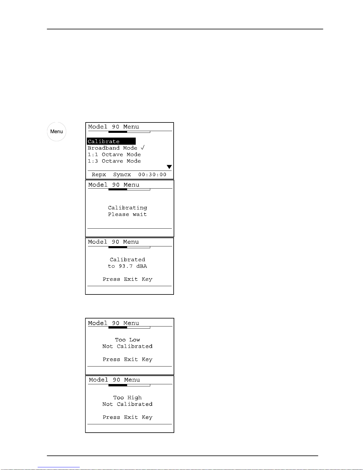
Attach the Acoustic Calibrator to the Sound Level Meter, and press the menu key. The
first menu option is Calibrate.
Key Press
Display
Comments
Select 94dB on the Acoustic
Calibrator before starting the
calibration procedure.
If the calibration is sucessful, the
instrument will display the
calibration information screen.
Press Exit to return to the main
screen.
If the instrument cannot calibrate successfully, the display will show an error:
The calibration level is to o low.
The Calibrator may not be
switched on or may not be
functioning correctly.
The calibration level is to o high.
Check that the calibration level on
the Acoustic Calibrator is set to
the correct level.
The default level is 94dB
Page 23
Model 90 Quantifier Sound Level Meter
Page 23
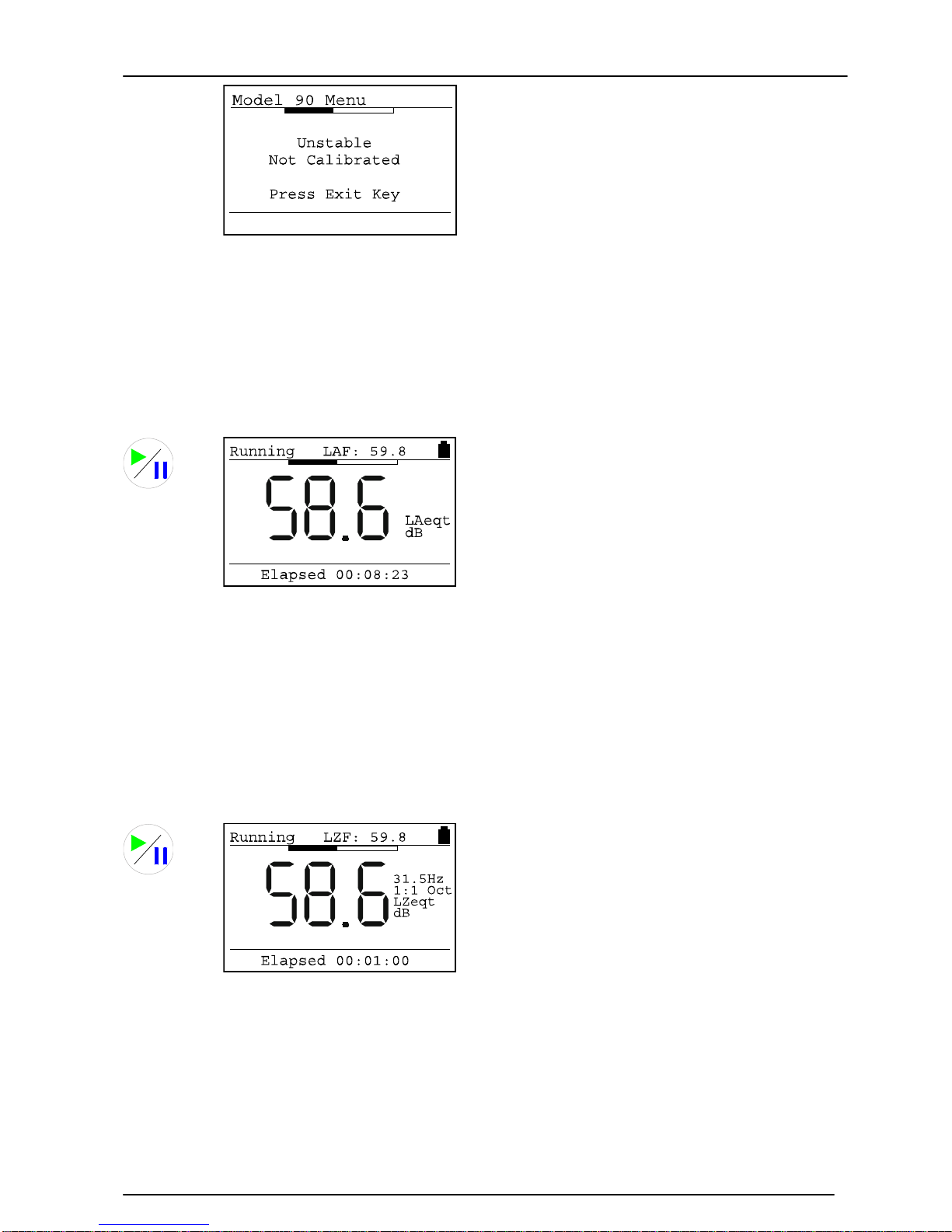
The calibration level is unstable.
The background noise level may
be too high or the Acoustic
Calibrator may not be fitted
correctly to the Sound Level
Meter.
Refer to the troubleshooting
section on page 54
for further
information.
Starting a measurement
Broadband Mode
Key Press
Display
Comments
When the measurement is
running, the display shows
“Running” in the top left hand
corner.
If the user does not stop or reset the measurement, the instrument will run for the
preset measurement duration. At the end of the measurement, the information will be
automatically stored in the memory.
If the Auto-Repeat function is enabled, the next measurement will start automatically at
the end of the previous measurement.
1:1 Octave Band Mode
Key Press
Display
Comments
When the measurement is
running, the display shows
“Running” in the top left hand
corner.
If the measurement duration is set to Manual, the 1:1 Octave Band frequency will stay
on the current frequency until the Up arrow is pressed. At the end of the measurement,
the user must press the Stop key to end the measurement and store the information in
the memory.
When the measurement duration is set to any option other than Manual, the instrument
will automatically sweep through the 1:1 Octave Bands in the set duration. After the
Page 24
Model 90 Quantifier Sound Level Meter
Page 24
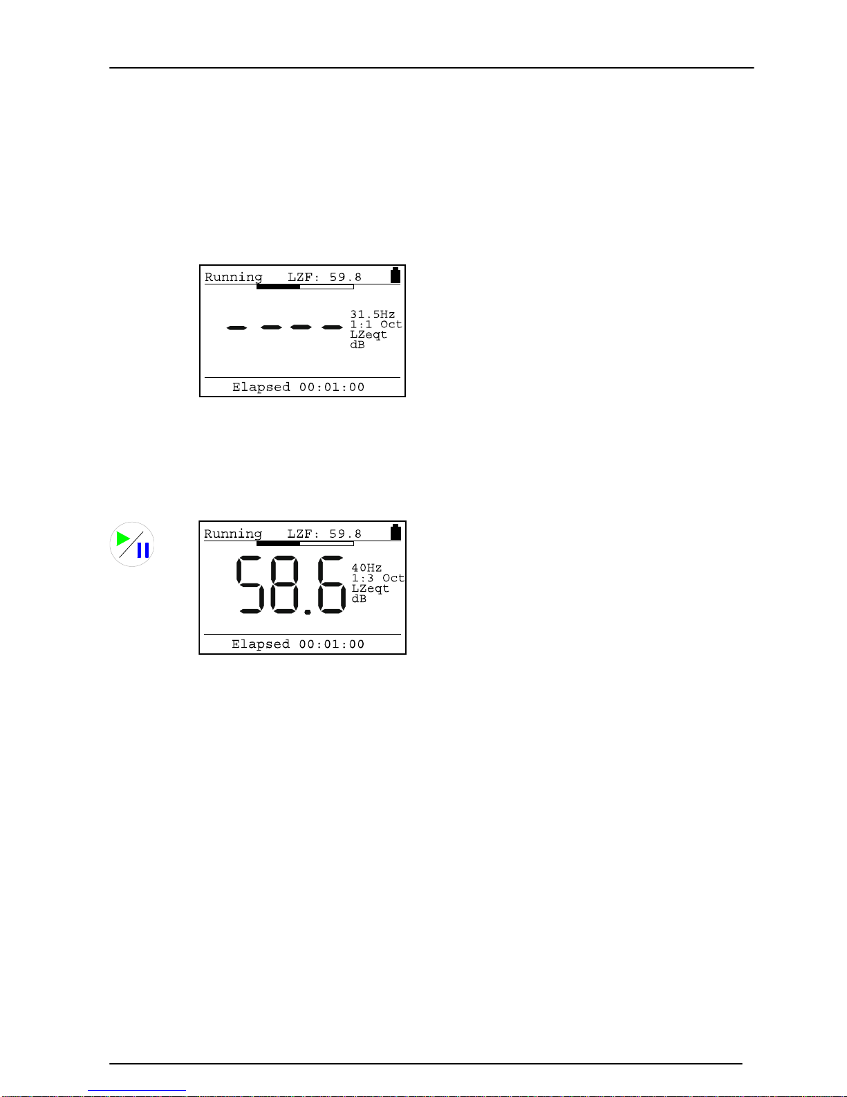
16kHz 1:1 Octave Band, the instrument will measure a dB(A), dB(C) and then a dB(Z)
value and then stop, storing the measurement in the memory.
The user can override the automatic sweep by pressing the Up arrow key to step to the
next frequency band.
The display will show ---- until enough data has been accumulated to give an accurate
measurement.
Key Press Display
Comments
The instrument has not
accumulated sufficient data to
give an accurate measurement.
When enough informati on has
been gathered, the LZeq value will
be displayed.
1:3 Octave Band Mode
Key Press Display
Comments
When the measurement is
running, the display shows
“Running” in the top left hand
corner.
If the measurement duration is set to Manual, the 1:3 Octave Band frequency will stay
on the current frequency until the Up arrow is pressed. At the end of the measurement,
the user must press the Stop key to end the measurement and store the information in
the memory.
When the measurement duration is set to any option other than Manual, the instrument
will automatically sweep through the 1:3 Octave Bands in the set duration. After the
16kHz 1:3 Octave Band, the instrument will measure a dB(A), dB(C) and then a dB(Z)
value and then stop, storing the measurement in the memory.
The user can override the automatic sweep by pressing the Up arrow key to step to the
next frequency band.
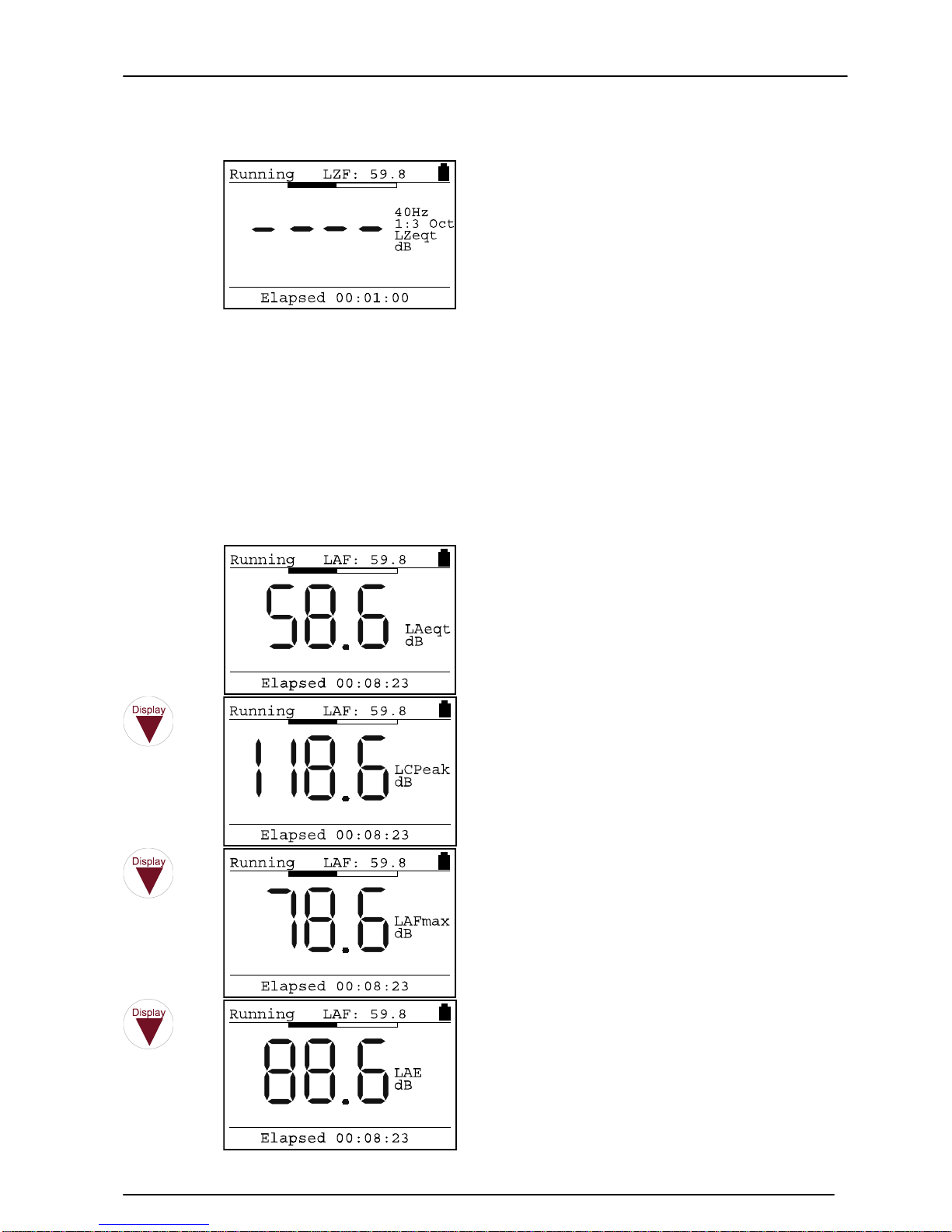
The display will show ---- until enough data has been accumulated to give an accurate
measurement.
Page 25
Model 90 Quantifier Sound Level Meter
Page 25
Key Press
Display
Comments
The instrument has not
accumulated sufficient data to
give an accurate measurement.
When enough informati on has
been gathered, the LZeq value will
be displayed.
Displaying the data during a measurement
Broadband Mode
During a Broadband Mode measurement, the user can step through the different
measurement parameters. All of the functions are measured simultaneously and are
automatically stored. Please note that this function is only available in Broadband Mode.
Key Press
Display
Comments
The instrument starts with the
LAeq,t value and the Elapsed
Time.
The Sound Level, in this case LAF,
is shown in the top right hand
corner of the screen.
The Peak(C) value is shown
The Maximum Sound Level,
LAFmax in this example, is shown
The Sound Exposure Level, or LAE
is shown.
If the User Metric is configured for
either the LAFTeq or LIeq,t
functions, these w ill be shown
instead of the LAE value.
Page 26
Model 90 Quantifier Sound Level Meter
Page 26
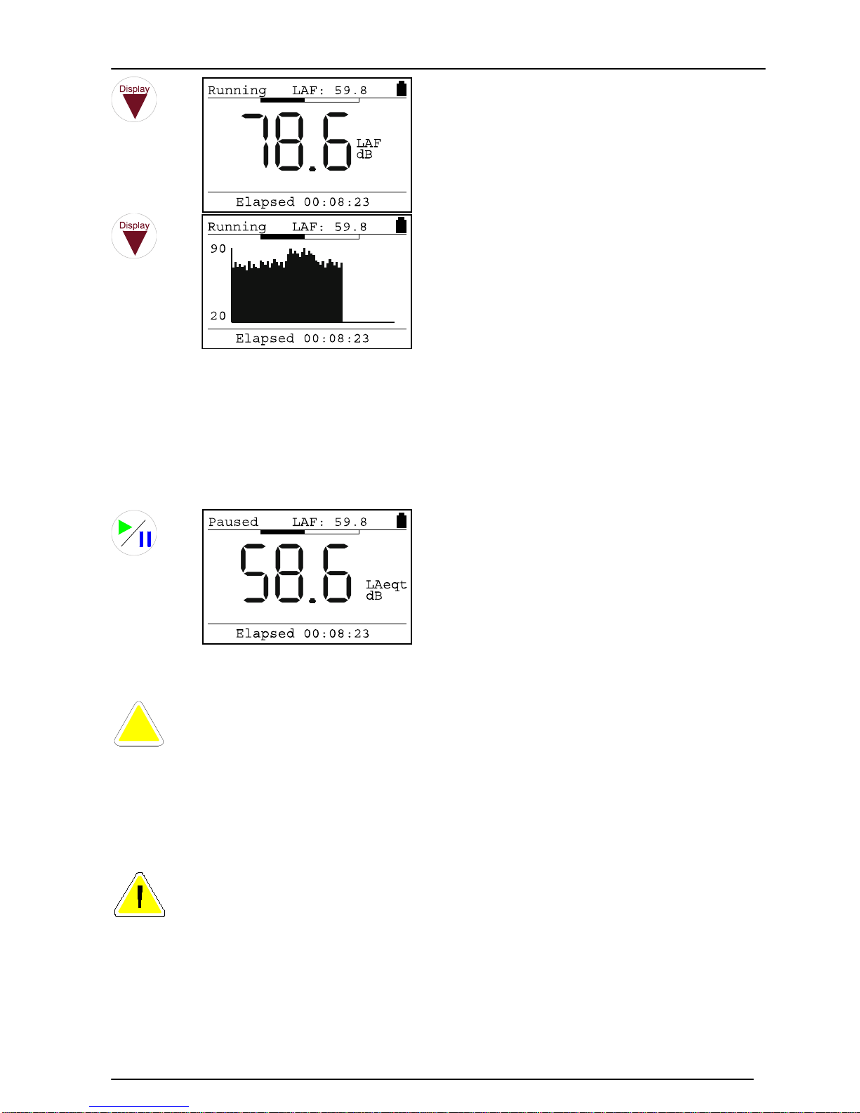
The Sound Level is shown, in this
case the LAF.
The real time display of the noise
level is shown as 1 second Leq
samples.
The display shows 2 minutes of
information and then starts to
scroll across the screen.
Pausing and Resetting a measurement
During a measurement, the user can pause the measurement by pressing the
Start/Pause key.
Key Press
Display
Comments
The measurement is paused.
To restart the measurement, press the Start/Pause key again.
When a Broadband measurement is paused, the collection of data for the
overall parameters, such a the Leq, is paused. However, the Time History
measurement continues and the instrument codes this data. When the
information is downloaded to the Analyser software, the user can see when the
measurement was paused.
Information recorded by the Time History store when the instrument is in pause mode
is not used in the calculation of the overall parameters.
The user can reset and discard the current measurement when the instrument
is running by pressing the Reset key. This will delete the current measurement
information and restart the measurement.
Stopping the measurement
At any time during a measurement, the user can stop the measurement. The data will
be automatically stored in memory, and the display will change to the memory review
mode.
i
Page 27
Model 90 Quantifier Sound Level Meter
Page 27
Key Press
Display
Comments
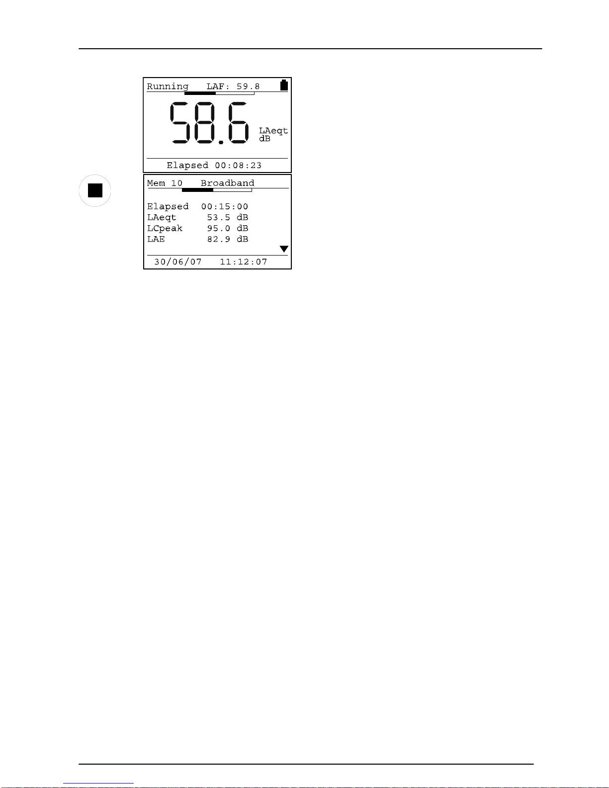
When the Stop key is pressed, the
current measurement is stored in
the memory and the display
changes to the memory review
mode.
In this example, the measurement
is a Broadband measurement.
Viewing the stored measurements
After a measurement has been stopped
When the measurement is stopped, the data is automatically stored in memory and the
instrument enters the measurement review mode.
Use the Up and Down arrow keys to review the measurement data. Refer to page 44 for
details of reviewing measurements.
Recalling stored measurements
Measurements can be recalled at any time to the instrument display. Refer to page 44
for details of recalling measurements.
Page 28
Model 90 Quantifier Sound Level Meter
Page 28
Section 3 Configuring the Sound Level Meter
This section of the manu a l covers the configuration of the Sound Level Meter a nd the
different options that are available to the user.
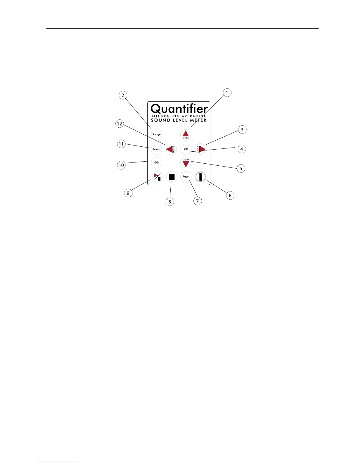
Keypad
(1) Move through the measurement parameters when running a measurement.
Move through the stored measurement parameters in memory recall mode.
Select a higher frequency band in 1:1 and 1:3 Octave Band Filter mode.
Step up through menu options
(2) Change the measurement range and display the current measurement range
(3) Enter Memory Recall Mode and step through the memory locations
(4) Select menu option. Accept data entry
(5) Move through the measurement parameters when running a measurement.
Move through the stored measurement parameters in memory recall mode.
Select a lower frequency band in 1:1 and 1:3 Octave Band Filter mode.
Step down through menu options
(6) Power On and Off
(7) Resets the current measurement when running
(8) Stops the current measurement when running
(9) Start and Pause a measurement
(10) Exit menu option. Cancel data entry
(11) Select the menu mode and view the menu options
(12) Enter Memory Recall Mode and step through the memory locations
Menu System
The MODEL 90 instruments use a menu system to allow the user to change the
operation of the Soun d Level Meter. This menu system is described below along with
the procedure to change the different measurement functions and operational
parameters.
Page 29
Model 90 Quantifier Sound Level Meter
Page 29
Measurement Mode
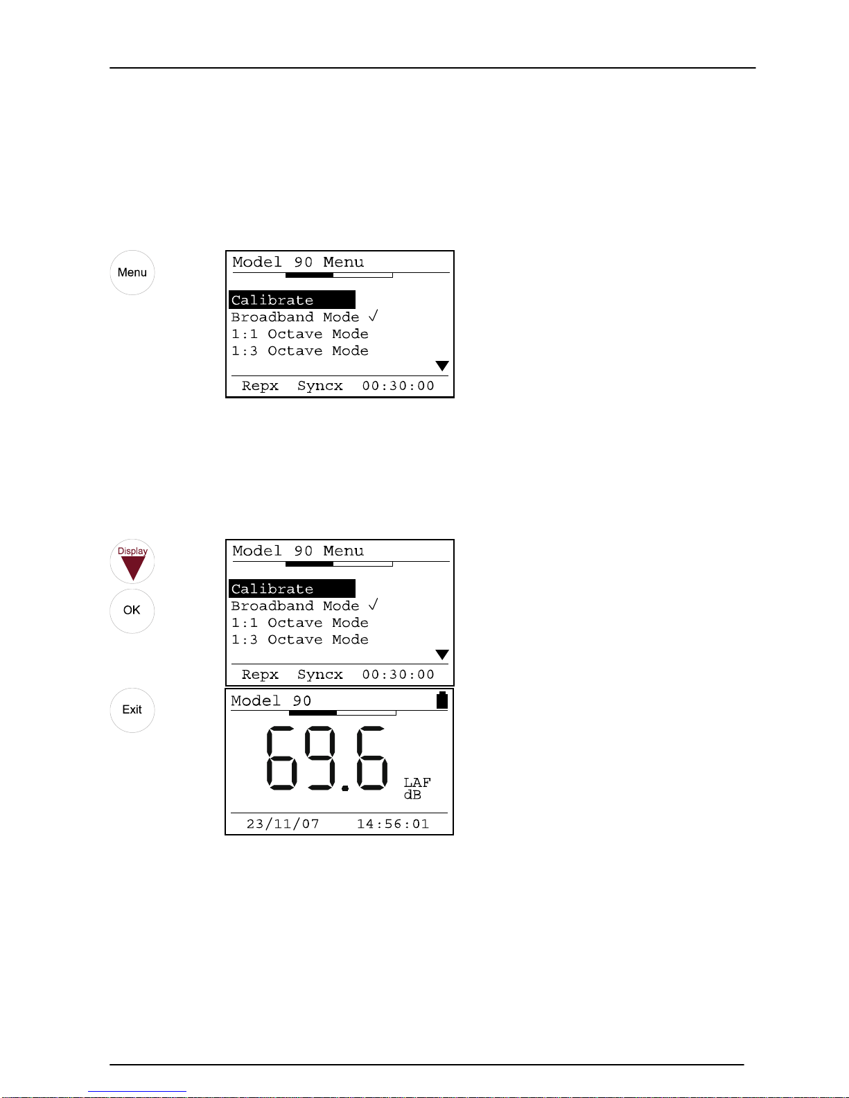
To select the Measure ment Mode, press the Menu Key. The current mea surement mode
is displayed. Please note that the MODEL 90 Sound Level Meters will revert to
Broadband Measurement Mode when the instrument is switched off.
Key Press
Display
Broadband Mode
To select the Broadband Measurement Mode:
Key Press
Display
Page 30
Model 90 Quantifier Sound Level Meter
Page 30
1:1 Octave Band Mode
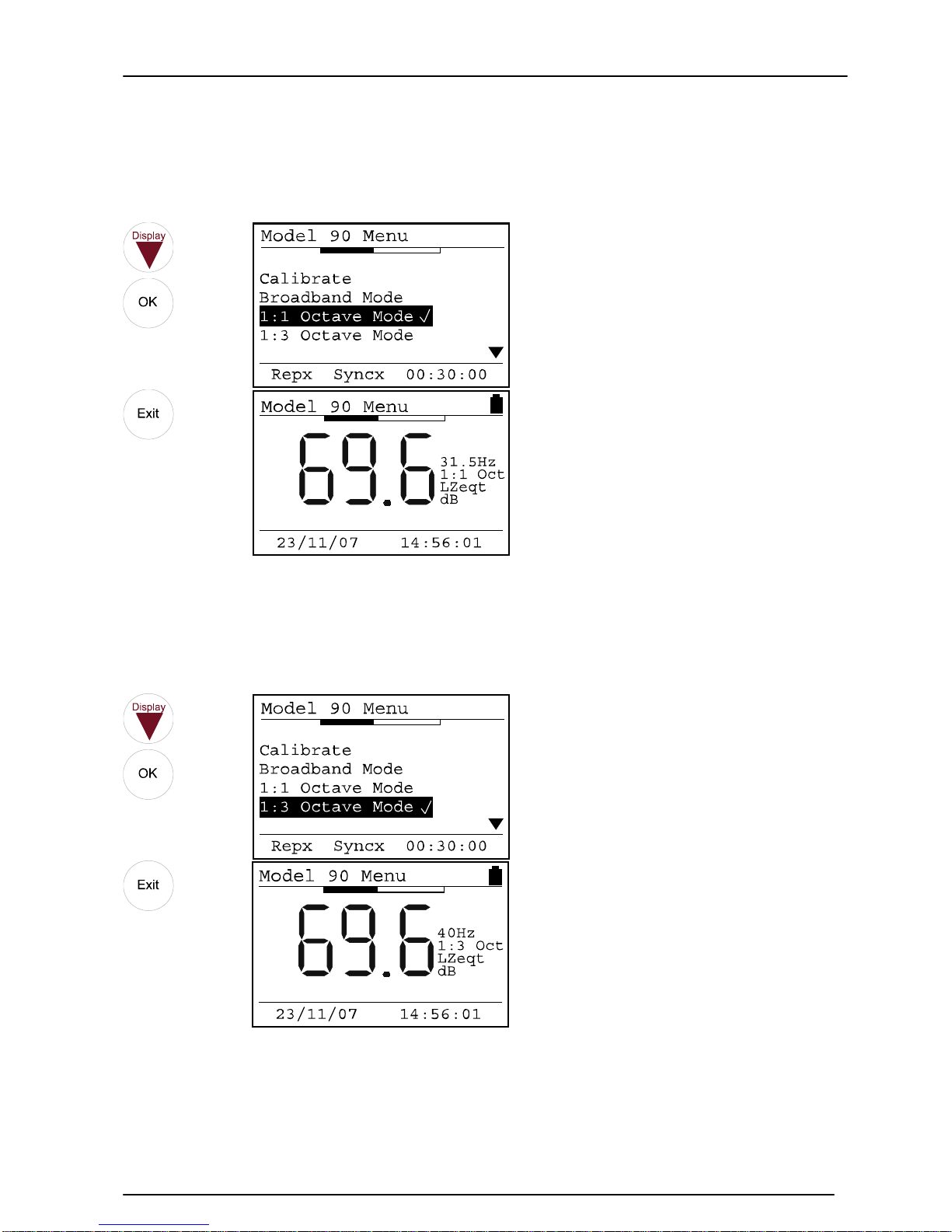
To select the 1:1 Octave Band Measurement Mode:
Key Press
Display
1:3 Octave Band Mode
To select the 1:3 Octave Band Measurement Mode:
Key Press
Display
Page 31
Model 90 Quantifier Sound Level Meter
Page 31
Measurement Duration
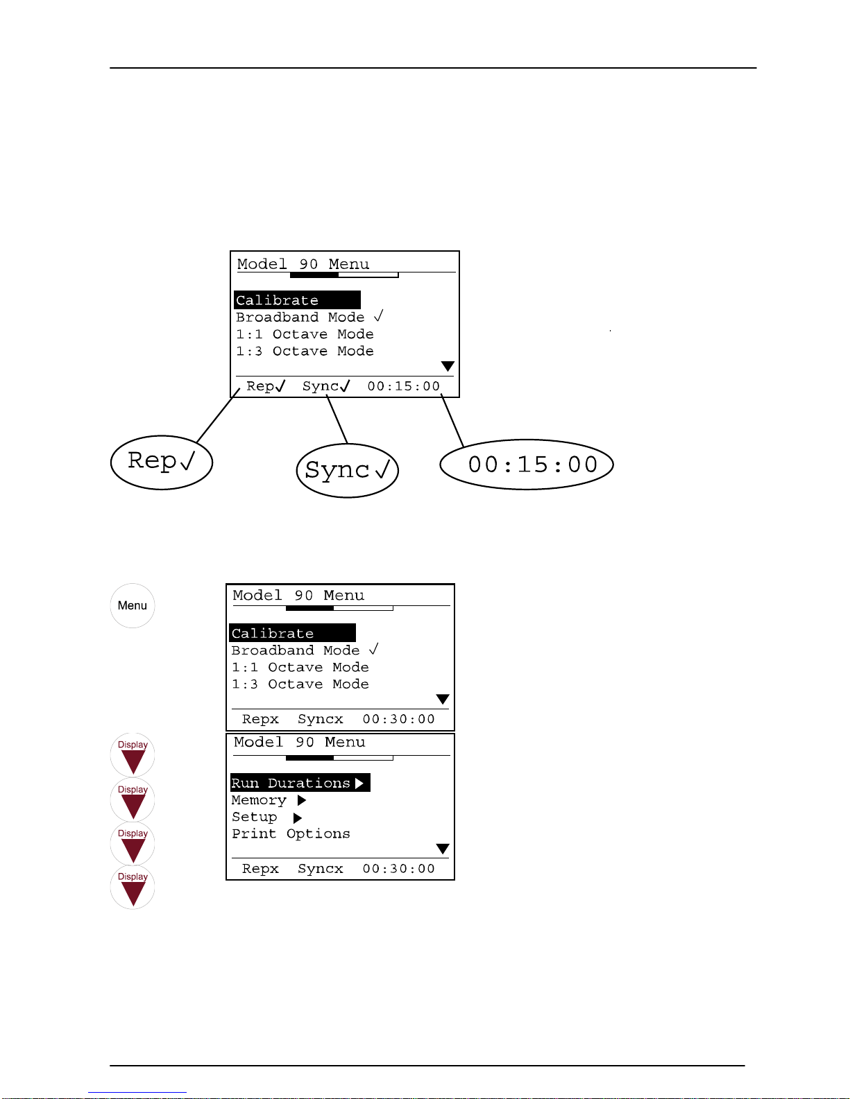
The configuration of the Run Duration, the Auto-Repeat and the Auto-Synchronise
functions are all connected and affect each other.
Always ensure that the status of these three functions is checked before making a
measurement. When the menu key is pressed, the display shows the status of these
functions as shown below.
To change the measurement duration of the instrument:
Key Press
Display
Page 32
Model 90 Quantifier Sound Level Meter
Page 32
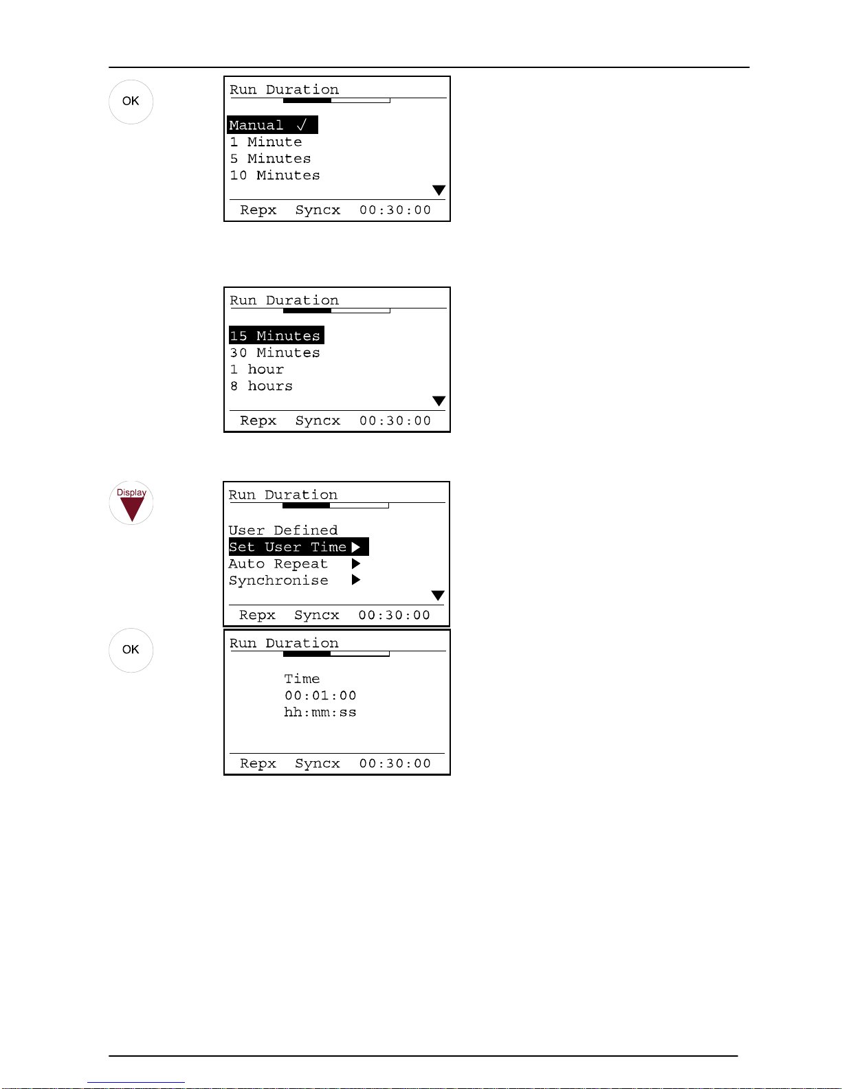
In this example, the measurement duration is set to 15 Minutes, and the instrument will run
continuously until the S t op key is pressed. The cha ng e the measurement duration, use the Up
and Down keys to select the require duration and press OK to select.
In addition to the preset measurement durations, the user can define the measurement duration
using the Set User Time Option.
Use the Up and Down keys to change the parameter and the Left and Right keys to move
through the different settings. Press OK to accept the User Time.
When the instrument is set to either 1:1 or 1:3 Octave Band Mode, the Run Duration is
divided between the frequency bands. For example, if the measurement duration is set
to 15 minutes, the MODEL 90 instrument will take a total of 15 minutes to complete
the sweep through the frequency bands.
To meet the accuracy required by the standards to which the instrument is designed to
meet, there is a minimum time required to measure each frequency band. Therefore,
the MODEL 90 enforces a minimum measurement duration of 1 minute for the 1:1
Octave Band Mode and 3 minutes for the 1:3 Octave Band Mode.
Page 33
Model 90 Quantifier Sound Level Meter
Page 33
Measurement Auto Repeat
The Auto Repeat function is used to set the instrument to make a series of contiguous
measurements. Please note that this function only operated in the Broadband
Measurement. Auto Repeat is not available during 1:1 or 1:3 Octave Band Mode.
For example, if the measurement duration was set to 15 minutes and the Auto Repeat
disabled, after one 15 minute measurement the instrument will stop and store the
measurement inf ormation the memory .
With the Auto Repeat function enabled, the instrument will make further 15 minute
measurements, one after the next until the total number of measurements has been
made. This allows the user to tell the instrument, for example, to make 96 individual 15
minute measurements over a 24 hour period.
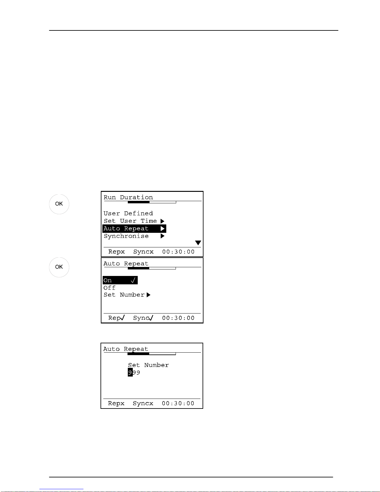
To configure the Auto Repeat function, enter t he menu and select the Measurement
Duration option and then select the Auto Repeat option.
Key Press
Display
Use the up and down arrows to ch a nge the number of measurements requir ed and the left and right arrows
to move between the digits. Press OK to accept the changes or Exit to discard any changes made.
Page 34
Model 90 Quantifier Sound Level Meter
Page 34
Measurement Auto Synchronise
This function is new to the MODEL 90 Series and allows the start of the measurements
to be started in time with the clock of the instrument.
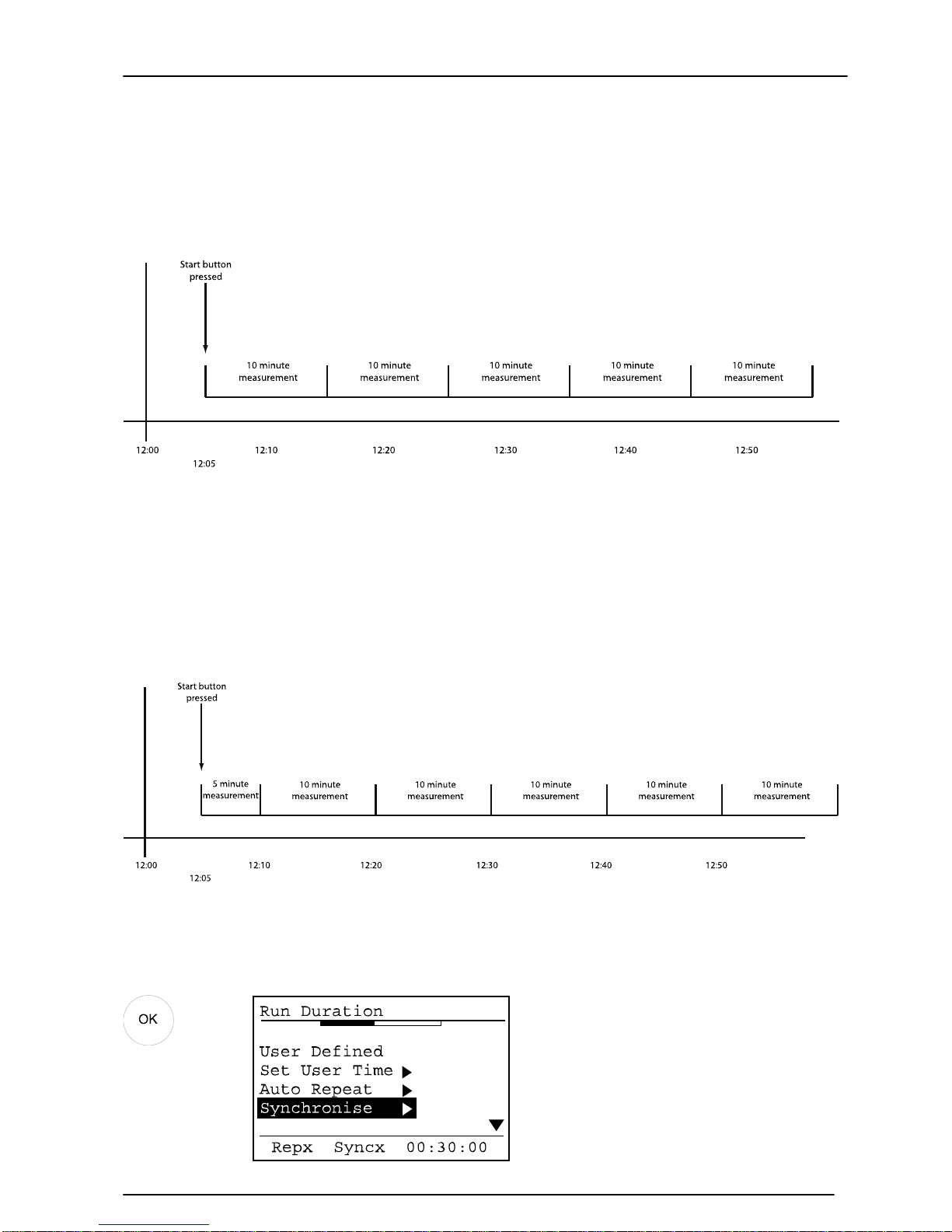
The diagram below shows how the measurement runs from when the Start key is
pressed for the duration defined by the Run Duration.
This method of starting and stopping the measurements is used, for example, when the
application is Occupational Noise and the user wants to control the starting and
stopping of the measurement directly.
However, in many applications such as Environmental Noise measurements, it is
important to start the measurements at a predetermined time. For example, when
making environmental noise measurements that are for 10 minutes, the MODEL 90 can
be set to start the measurements on 10 minute boundaries.
The diagram below show the measurement starts with the Auto Sync function enabled.
To enable the Auto Sync function, select the Run Duration option from the menu and
then select the Synchronise function. Use the Up and Down arrows to switch on the off
the Auto Synchronise function. Press Exit when finished.
Key Press
Display
Page 35
Model 90 Quantifier Sound Level Meter
Page 35
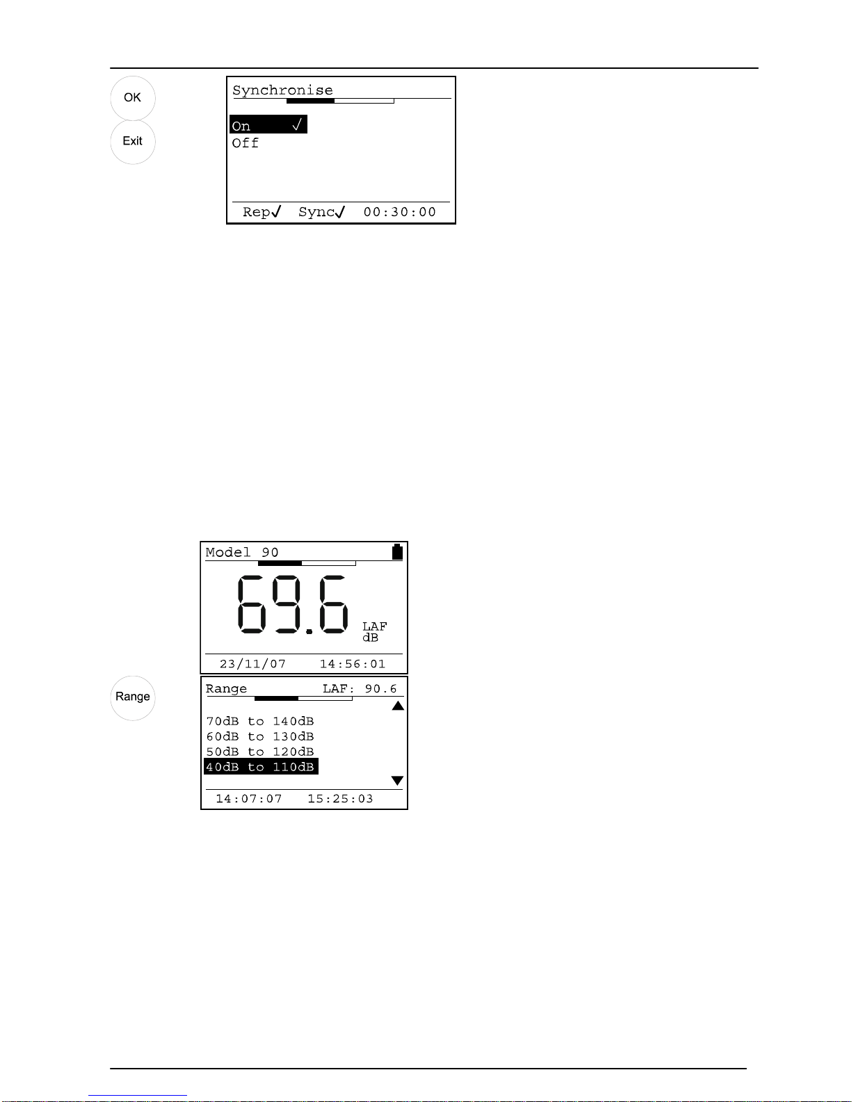
When the Auto Synchronise function has been selected, the display will show the Sync
at the bottom of the screen with a tick next to it as shown above.
Measurement Range
One of the most important features of a Sound Level Meter is the measurement range.
If the measurement range is set too high, the instrument may not be able to record low
levels. If the measurement range is set too low, high noise levels will overload the
instrument and make the measurement invalid.
Therefore it is vital that the correct measurement range is chosen for the noise to be
recorded.
To check the current measurement range, press the Range key.
Key Press
Display
Comments
The current measurement range is
40dB to 110dB.
The measurement range in this example is 40dB to 110dB. If the noise level is below
40dB, the instrument will indicate Under-Range. If the noise lev el is above 110dB, the
instrument will indicate Overload. See page 54 for an explanation of Overload and
Under-Range.
Page 36
Model 90 Quantifier Sound Level Meter
Page 36
Display
Comments
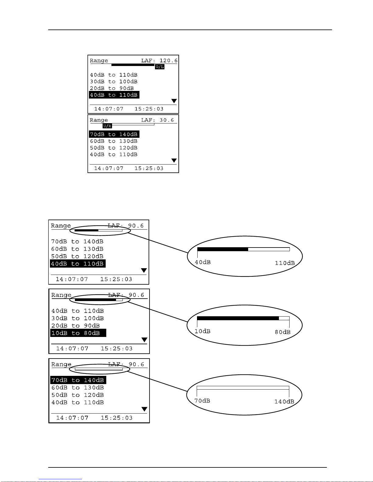
The measurement range is 40dB
to 110dB and the noise level is
120.6dB.
The instrument is overloading and
the O/L symbol is shown.
The measurement range is 70dB
to 140dB and the noise level is
58.9dB.
The instrument is unde r ranging
and the U/L symbol is shown.
The bar graph at the top of the screen can be used to select the appropriate
measurement range. As the user moves between the different measurement ranges,
the bar graph changes the top and bottom to match the measurement range. The noise
level being measured is shown in the bar graph.
The diagram above shows how the bar graph will show where the noise level is
placed within the selected measurement range. Select the appropriate measurement
range to suit the noise levels to be measured.
Page 37
Model 90 Quantifier Sound Level Meter
Page 37
Instrument Setup
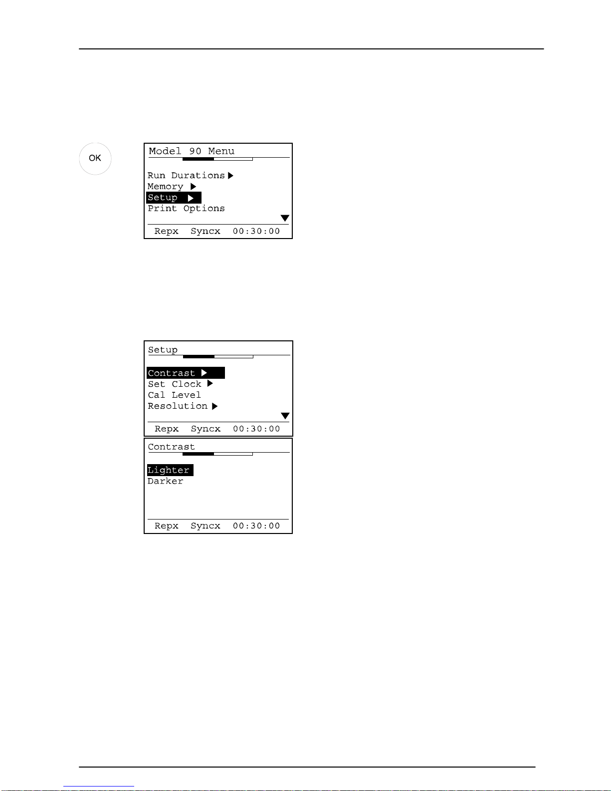
Select the Setup option from the main menu and press OK.
Key Press
Display
Comments
Display Contrast
To adjust the contrast of the display, select the Contrast Option and press OK
Key Press
Display
Comments
Select the Lighter or Darker option
and press the OK repeatedly to
adjust the selection.
Press the Exit button to exit from
the Contrast menu.
Page 38
Model 90 Quantifier Sound Level Meter
Page 38
Time & Date
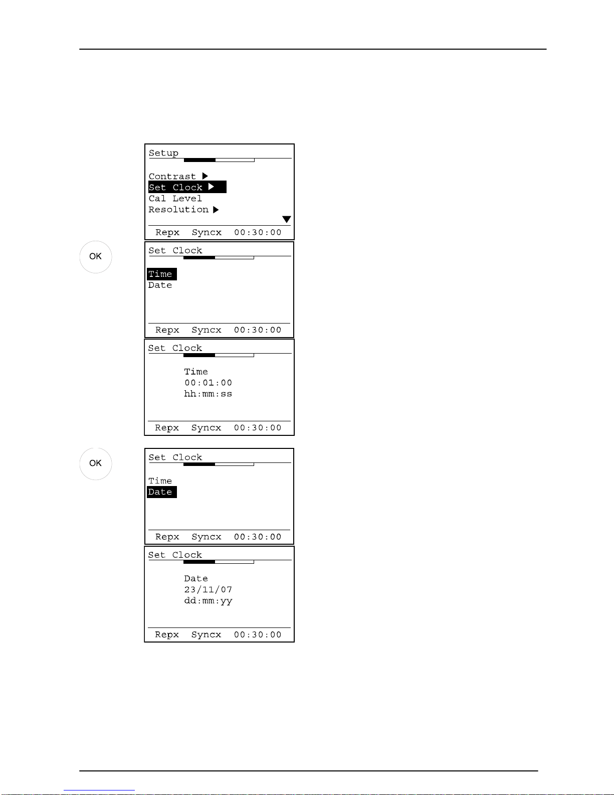
To change the Date and Time, select the Set Clock option from the Setup Menu.
Key Press
Display
Comments
To set the Time, select the Time
option and press OK
Use the Up and Down arrow keys
to change the numbers and the
left and right arrow keys to move
between the numbers.
Press the OK key when the Time is
correctly set.
To set the Date, select the Date
option and press OK
Use the Up and Down arrow keys
to change the numbers and the
left and right arrow keys to move
between the numbers.
Press the OK key when the Time is
correctly set.
Calibration Level
The level at which the MODEL 90 instrument calibrates can be adjusted, if required, to
suit different Acoustic Calibrators.
Page 39
Model 90 Quantifier Sound Level Meter
Page 39
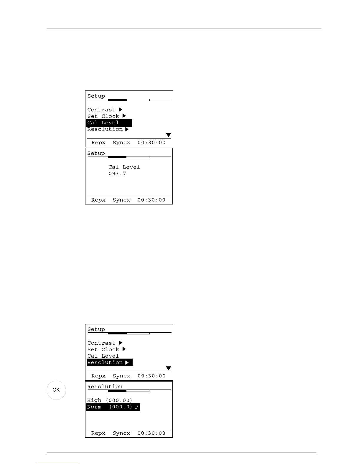
The default calibration level is 93.7dB for use with Pulsar Instruments Plc Acoustic
Calibrators set to the 94dB setting. The correction of –0.3dB is required to suit the
MK:224 and MK:216 Microphone capsules used by the MODEL 90 Series.
To adjust the calibration level, select the Cal Level option from the setup menu.
Key Press
Display
Comments
Use the Up and Down arrows to
adjust the level and the Left and
Right arrow keys to move between
the numbers.
Press OK to accept the calibration
level.
Pulsar Instruments Plcdoes not recommend the use of Acoustic Calibrators other than
those manufactured or supplied by Pulsar Instruments Plc for use with the MODEL 90
instruments.
Refer to the operating manual supplied with the Acoustic Calibrator to be used for
details of the correction required for use with an MK:224 or MK:216 Microphone
Capsule.
Display Resolution
The display resol uti on of the MODEL 90 instruments can be set to be either 0.1dB or
0.01dB. For most applications, the 0.1dB resolution is standard.
Key Press
Display
Comments
Use the Up and Down arrows keys
to select the display resolution
and press OK to select the
required display resolution.
Press Exit to return to the main
display.
Page 40
Model 90 Quantifier Sound Level Meter
Page 40
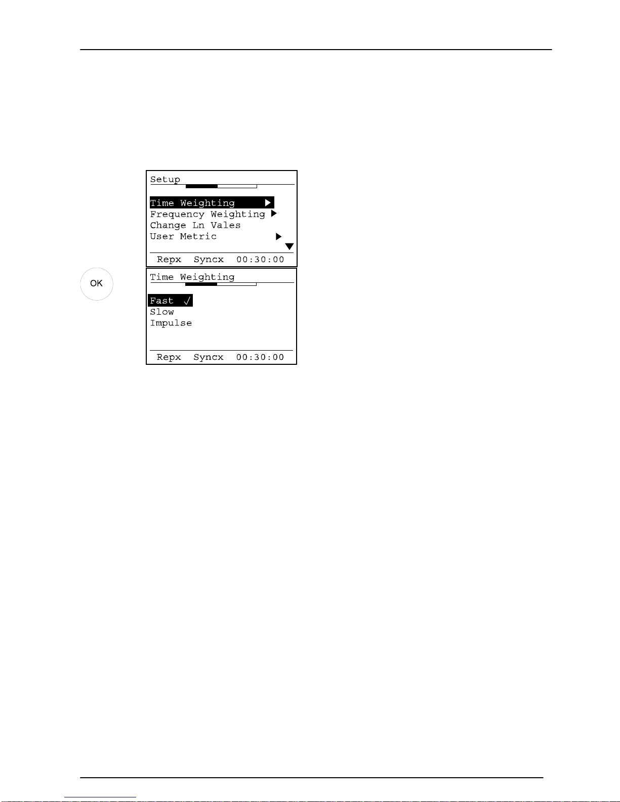
Time Weighting
The Time Weighting of the instrument can be set to either Fast, Slow or Impulse. To set
the Time Weighti ng, select the Time Weighting option from the menu:
Key Press
Display
Comments
Select the requi red Time
Weighting and press OK to select.
The select Time Weighting is
indicated by a tick.
Press Exit to return to the main
display.
The Time Weighting applies to the following parameters:
Broadband Mode
L
AF,LAS,LAI,LCF,LCS,LCI,LZF,LZS
or LZI (not stored)
L
AFmax,LASmax,LAImax,LCFmax,LCSmax,LCImax,LZFmax,LZSmax
or L
ZImax
L
AFmin,LASmin,LAImin,LCFmin,LCSmin,LCImin,LZFmin,LZSmin
or L
ZImin
L
0.1
to L
99.9
(five simultaneous user-selected values available)
The L
n
’s or Statistical parameters are calculated from Sound Level. Therefore, if the
Time Weighting is set to Fast, the L
n
’s will be calculated from LAF, and also for the Slow
and Impulse Time Weightings.
1:1 Octave Band Mode
Filtered L
ZS,LZF
or LZI (not stored)
1:3 Octave Band Mode
Filtered L
ZS,LZF
or LZI (not stored)
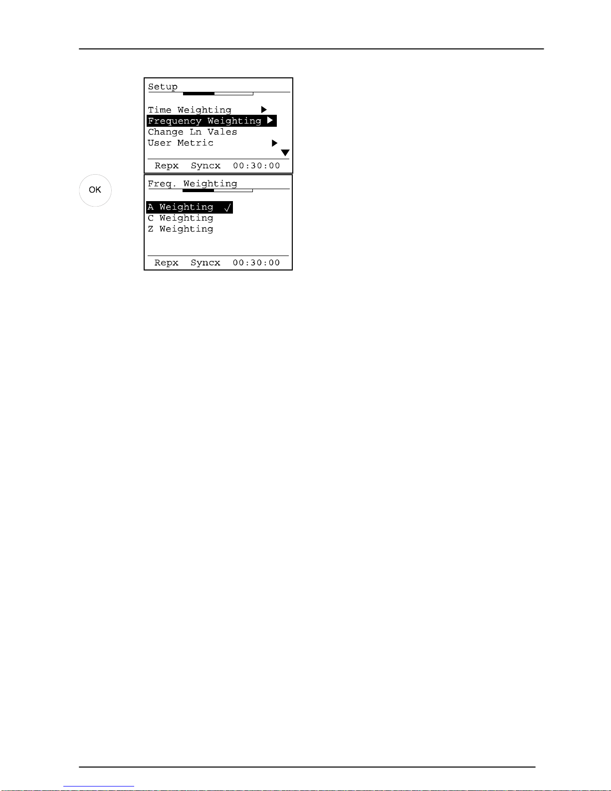
Frequency Weighting
The Frequency Weighting of the instrument can be set to either A, C or Z. To set the
Frequency Weighting, select the Frequency Weighting option from the menu:
Page 41
Model 90 Quantifier Sound Level Meter
Page 41
Key Press
Display
Comments
Select the required Frequency
Weighting and press OK to select.
The select Frequency Weighting is
indicated by a tick.
Press Exit to return to the main
display.
The Frequency Weighting applies to the following parameters:
Broadband Mode
Integrated Sound Level L
Aeq,LCeq
, or LZeq
Sound Level L
AF,LAS,LAI,LCF,LCS,LCI,LZF,LZS
or LZI (not stored)
Maximum Sound Leve L
AFmax,LASmax,LAImax,LCFmax,LCSmax,LCImax,LZFmax,LZSmax
or L
ZImax
Minimum Sound Level L
AFmin,LASmin,LAImin,LCFmin,LCSmin,LCImin,LZFmin,LZSmin
or L
ZImin
User Metric L
AE,LCE
,or LZE,L
AIeq,LCIeq
, or L
ZIeq
, L
AFTeq
1:1 Octave Band Mode
No measurements are affected by the Frequency Weighting. All 1:1 Octave Bands are
measured with the Z Frequency Weighting.
1:3 Octave Band Mode
No measurements are affected by the Frequency Weighting. All 1:3 Octave Bands are
measured with the Z Frequency Weighting.
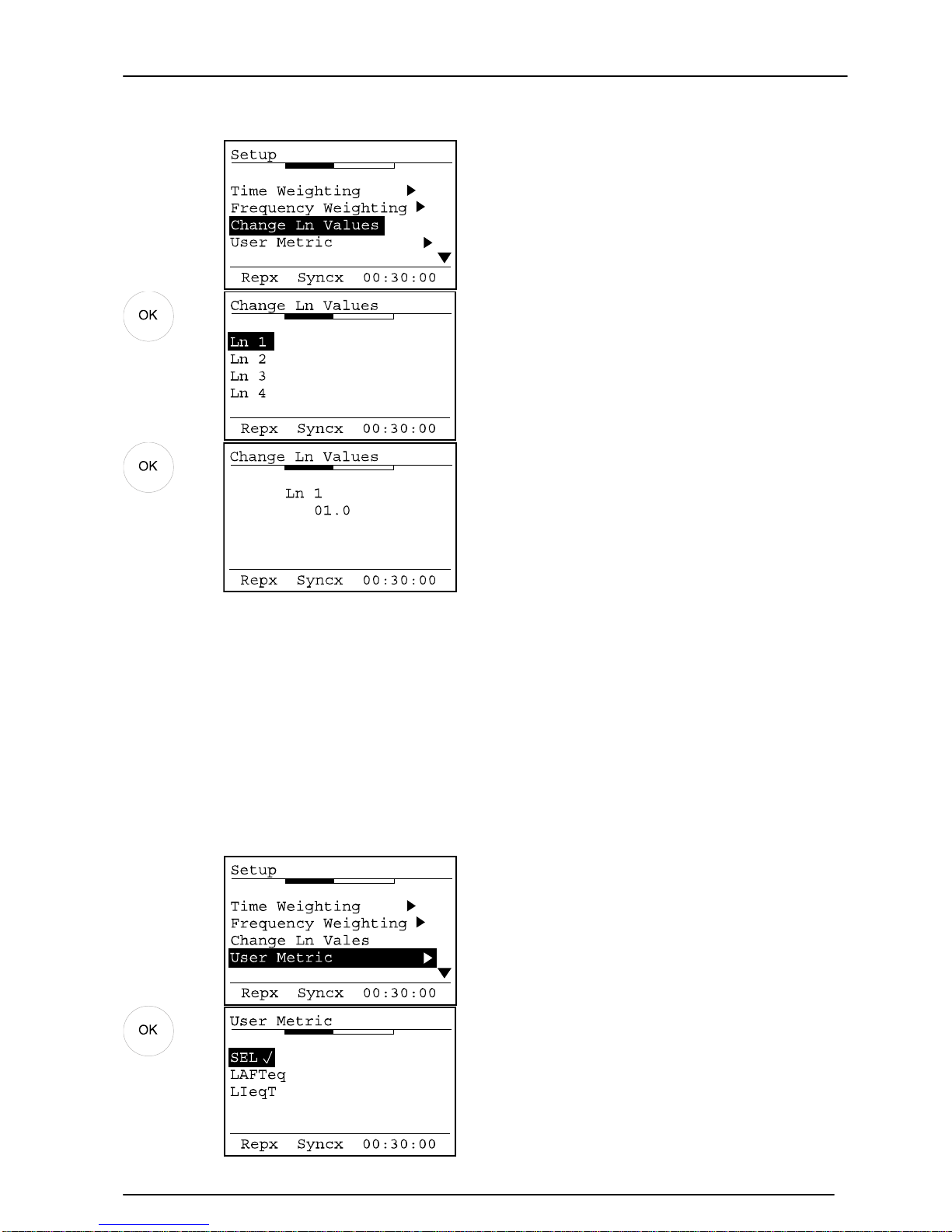
Ln values
The five preset Ln or Statistical values that are calculated at the end of a Broadband
measurement can be configured to different values.
The default values are L
1.0
, L
10.0
, L
50.0
, L
90.0
and L
95.0
To change the Ln values, select Change Ln Values from the Setup Menu.
Page 42
Model 90 Quantifier Sound Level Meter
Page 42
Key Press
Display
Comments
The Ln to be changed can be
selected using the Up and Down
arrow keys.
Press OK to select the Ln to
change.
In this example, the Ln1 has been
selected.
Use the Up and Down arrow keys
to change the value an d the Left
and Right arrow keys to move
between the numbers.
Press OK to accept the changes or
Exit to discard any changes.
The other Ln values can be altered in the same manner as shown above.
User Metric
The additional measurement parameter provided the MODEL 90 instrument is known as
the User Metric. This measurement parameter can be selected to be either L
E
(Sound
Exposure Level, SEL), L
Ieq,t
(Impulse Weighted Time Weighted Sound L evel) or L
AFTeq
(Takt Maximal Soun d Lev el).
Key Press
Display
Comments
Select the required User Metric
and press OK to select.
The select User Metric is indicated
by a tick.
Press Exit to return to the main
display.
Page 43

Model 90 Quantifier Sound Level Meter
Page 43
Note that if the LIeq ,t function is selected, the MODEL 90 will automatically
select the Impulse Time Weighting which will apply to all other measurement
functions described in section Time Weighting on page 40.
Before the Time Weighting can be selected to either Fast or Slow, the User Metric must
be set to SEL.
Configuring the instrument from the Analyser software
The entire configuration of the instrument can be set from the Analyser software using
the Advanced Configuration option. Please refer to page 68 for details of this function.
Page 44
Model 90 Quantifier Sound Level Meter
Page 44
Section 4 Viewing and Downloading the measurements
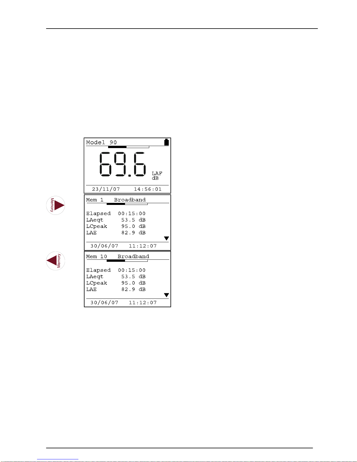
When a measurement stops, either by the user pressing the Stop key or when a
measurement stops automatically, the data is automatically stored in the memory.
Recalling Stored Measurements
To view stored measurements, ensure that the instrument is not running. Press the
right hand arrow key to view the first stored measurement and the left hand arrow key
to view the last measurement stored.
Key Press
Display
Comments
The first measurement stored is
shown.
The parameters displayed depend
upon the measurement type.
The last measurement stored is
shown.
The parameters displayed depend
upon the measurement type.
The measurement type is shown at the top of the screen next to the measurement
number. The different measurement types have different parameters that are displayed
and these are described below
Page 45
Model 90 Quantifier Sound Level Meter
Page 45
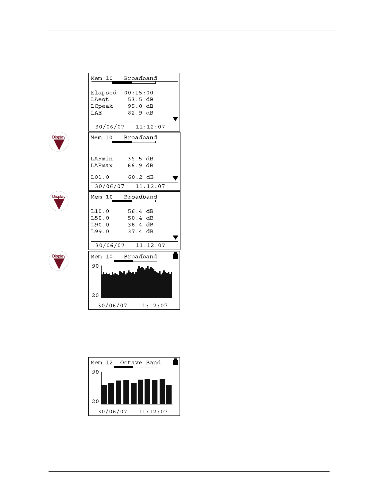
Broadband Measurement
Key Press
Display
Comments
The User Metric setting of the
instrument determines if the unit
stores LAE, LAIeq,t or LAFTeq.
If the unit was in Overload or
Under-Range during the
measurement this is indicated on
the screen.
The whole measurement duration
is displayed on the sc reen when
the Time History data is reviewed.
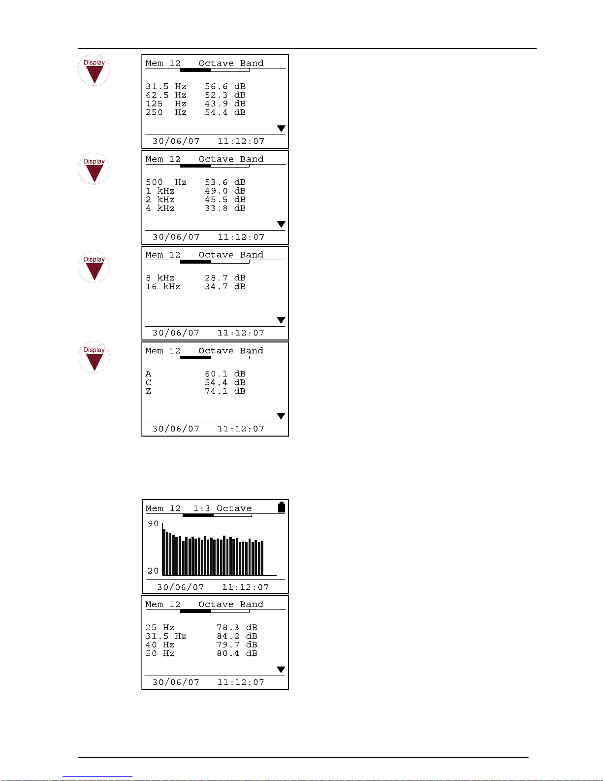
1:1 Octave Band Measurements
Key Press
Display
Comments
The graphical display of the 1:1
Octave Band measurement is
shown with the measurement
range shown on the left hand
scale.
Page 46
Model 90 Quantifier Sound Level Meter
Page 46
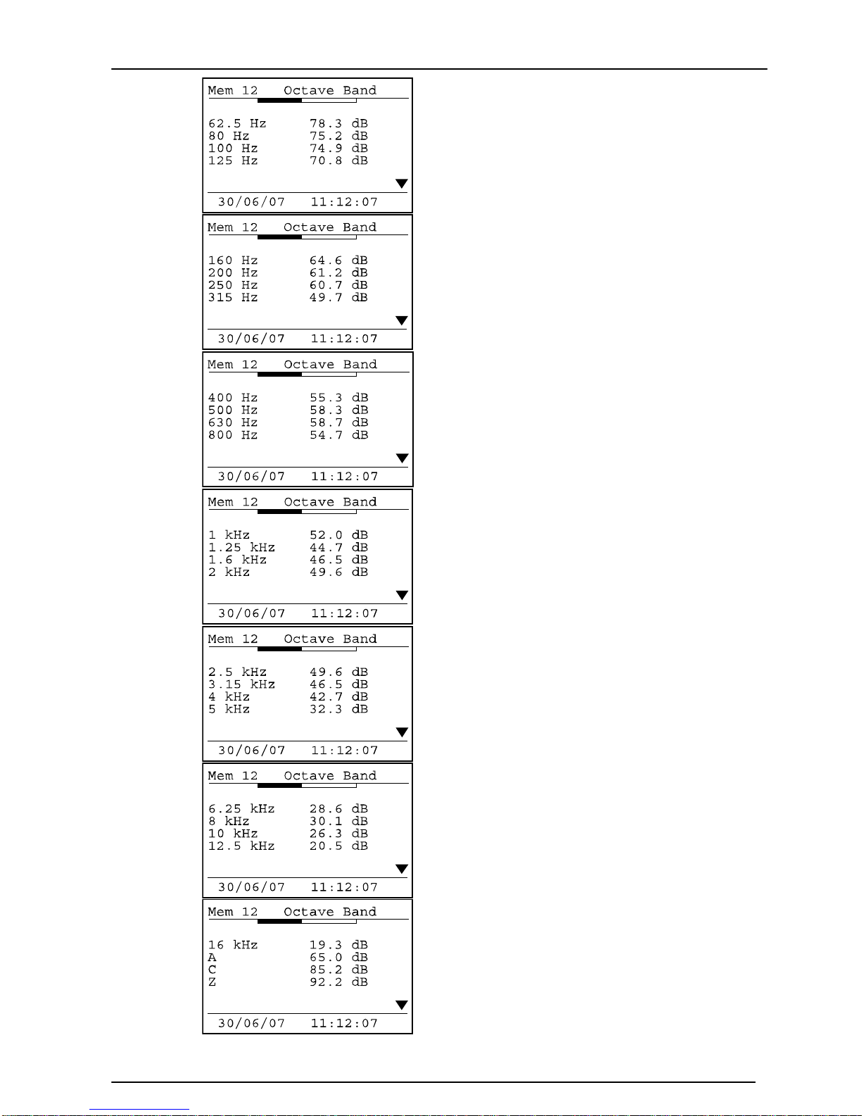
1:3 Octave Band Measurements
Key Press
Display
Comments
The graphical display of the 1:3
Octave Band measurement is
shown with the measurement
range shown on the left hand
scale.
Page 47
Model 90 Quantifier Sound Level Meter
Page 47
Page 48
Model 90 Quantifier Sound Level Meter
Page 48
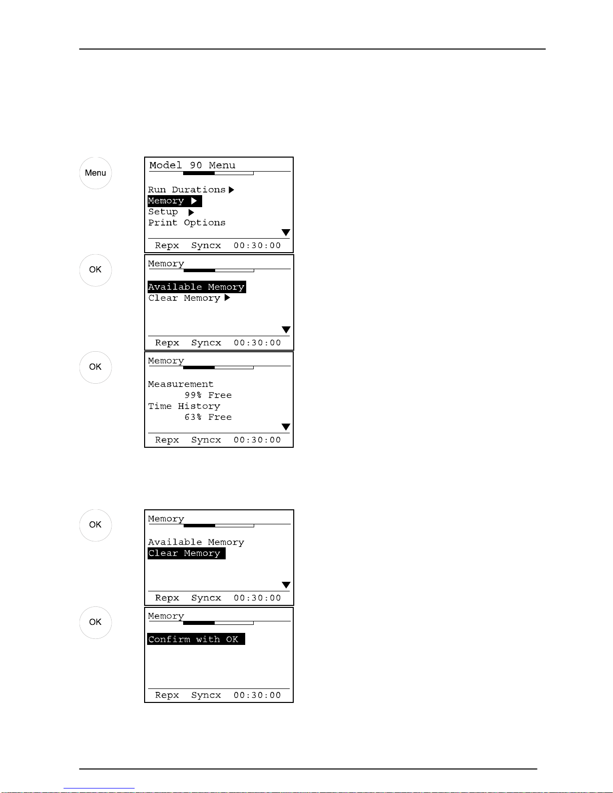
Checking & Clearing the memory
The memory of the instrument can be checked for available space and also to allow the
user to delete the measurements that are stored. To check the available memory,
select the Memory op t ion from the menu:
Key Press
Display
Comments
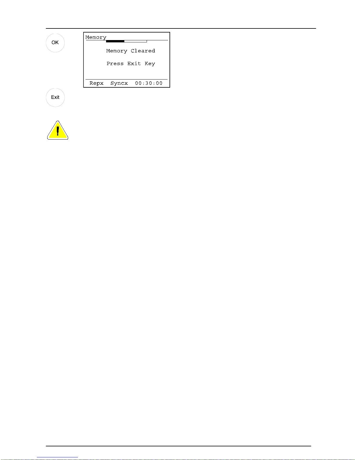
To clear all the measu r ements from the memory, use the Clear Memory option:
Key Press
Display
Comments
Page 49
Model 90 Quantifier Sound Level Meter
Page 49
Please note that when the memory has been cleared, any measurement
previously stored cannot be retrieved and are permanently deleted.
Page 50
Model 90 Quantifier Sound Level Meter
Page 50
Downloading Measurements to the Software
Before measurements can be downloaded, the software must be installed on to a
suitable PC.
Software Installation
The Analyser software must be installed before measurements can be downloaded.
Please refer to page 67 for details of the installation of the Analyser software.
Connecting the instrument to the PC
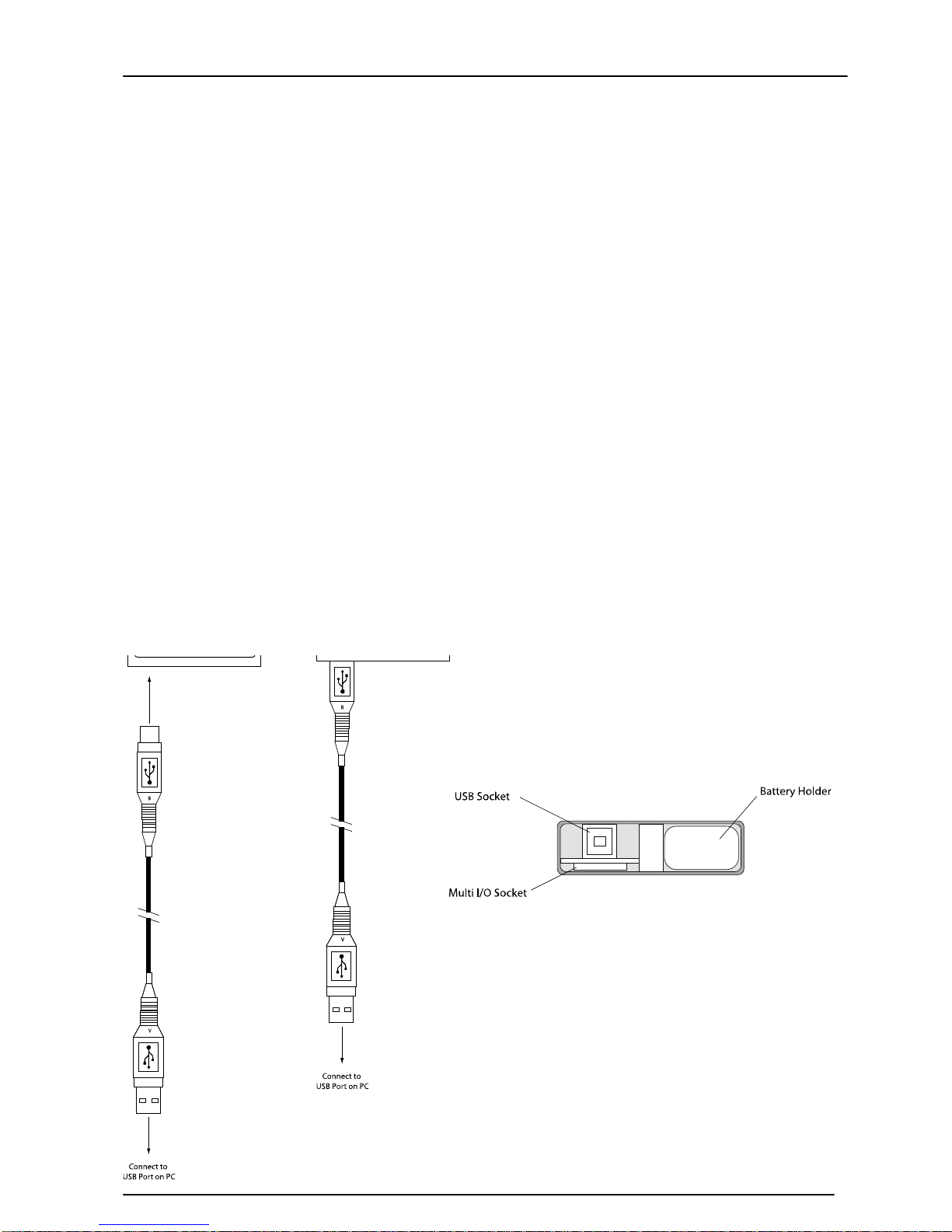
The MODEL 90 instruments connect to the PC using the supplied DC:80 USB Cable.
Connect the DC:80 USB Cable to the USB socket on the bottom of the instrument.
Ensure that the cable is inserted correctly with the arrow on the top of the connector.
Do not force the connector into the socket as this may cause damage.
When the Analyser software is installed and run, use the Download option to connect to
the instrument. Please refer to the Help provided with the Analyser software for details
of the download procedure.
Page 51
Model 90 Quantifier Sound Level Meter
Page 51
Understanding how the measurements are stored
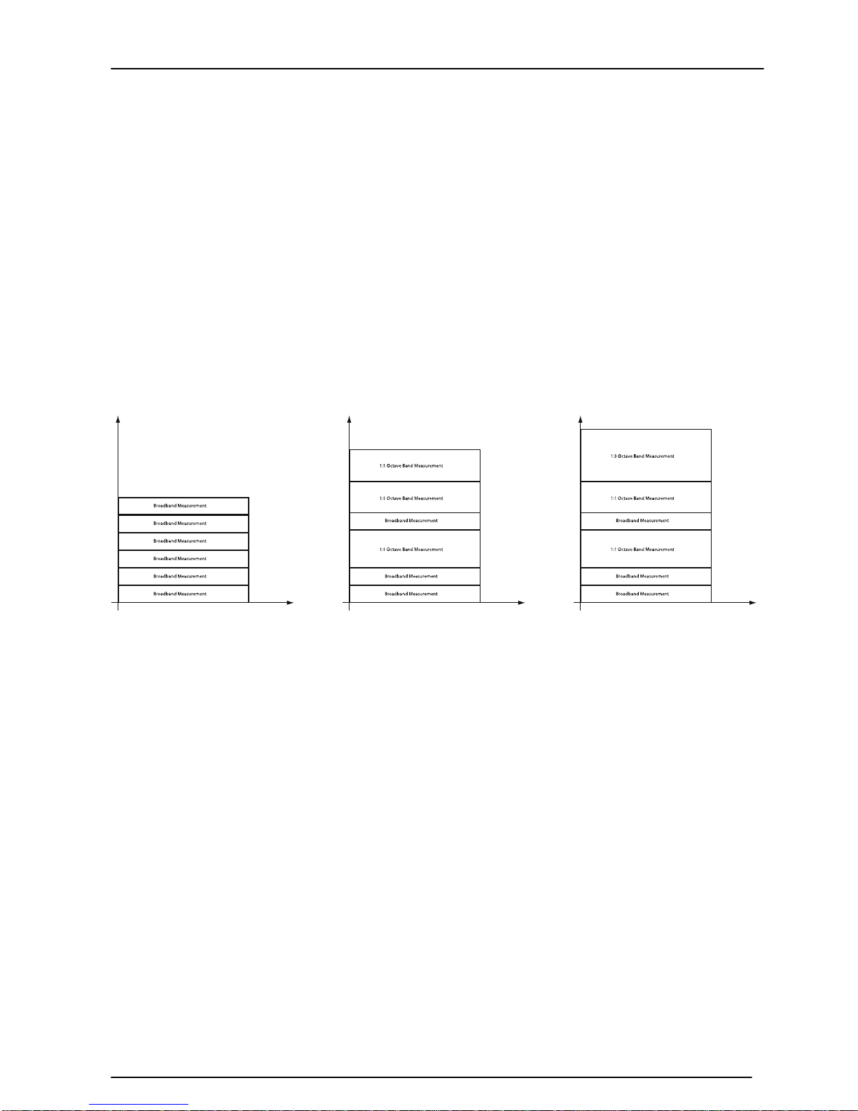
The memory of the MODEL 90 can store up to 1,300 measurements. Each
measurement is known as an Event and can be either Broadband, 1:1 Octave Band or
1:3 Octave Band.
The duration of each measurement does not affect the size that it takes, but the
different measurements types take up different amounts of space in the instrument
memory.
For example, a Broadband measurement take 1 memory slot, a 1:1 Octave
measurement takes 2 memory slots and a 1:3 Octave measurement takes 3 memory
slots.
The diagram below shows how the different measurements take up different amounts
of memory space.
The maximum time over which Broadband measurements can be stored depends upon
the duration of the measurement. The table below shows the maximum time over
which measurements can be made. Please note that this applies only to Broadband
Measurements using the Auto Repeat function.
Measurement Duration
Maximum Length of Measurement
1 minute
21.5 hours
5 minutes
4.5 days
15 minutes
13.5 days
30 minutes
27 days
1 hour
54 days
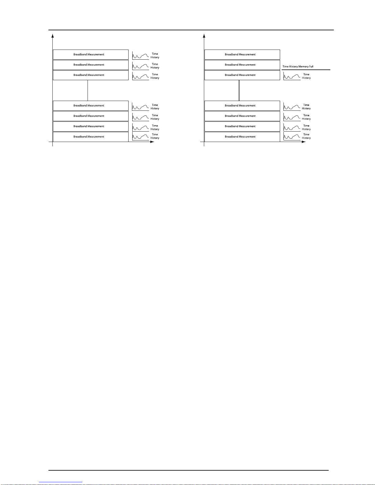
With each Broadband Measurement is also stored a Time History measurement. This
information is stored in a separate memory from the Events and does not take up any
of the 1,300 Event mem or ies. However, the Time History memory is limit ed to a size of
1,008,000 samples at 1 second samples, which is just over 11 days of data storage.
If the Time History Store is full before the Event Memory Store, the Even t
measurements will continue but will not have Time History data.
The diagram below shows an example of this.
Page 52
Model 90 Quantifier Sound Level Meter
Page 52
Page 53

Model 90 Quantifier Sound Level Meter
Page 53
Section 5 Maintenance & Care
The MODEL 90 is a precision measurement instrument and should be treated with care.
Do not allow the instrument to be exposed to substances which may cause damage to
the components of the unit. If the instrument is to be used in an environment where
particles such as dust may come into contact with the instrument, always use a
Windshield (WS:90) to protect the microphone capsule.
The MODEL 90 is not waterproof and should not be used in situations where moisture
will form or condense on the microphone capsule or the instrument body. If using the
MODEL 90 outdoor, use a suitable outdoor measurement kit which has been specifically
designed to protect the instrument.
If the MODEL 90 becomes dusty, wipe it down with a cloth that is lightly dampened with
water or a mild detergent. Do not use aromatic hydrocarbons, chlorinated solvents, or
methanol-based fluids when wiping down the meter.
Do Not clean the mi croph on e capsule. Do Not remove the microphone gril l as this can
cause severe damage to the membrane. Physical damage to the microphone capsule is
not covered by the instrument warranty.
If you experience any problems with the operation of the instrument, refer to page 54
for basic troubleshooting. If this does not solve the problem, contact P ulsar Instruments
Plc your local representative for further assistance.
Page 54
Model 90 Quantifier Sound Level Meter
Page 54
Section 6 Troubleshooting
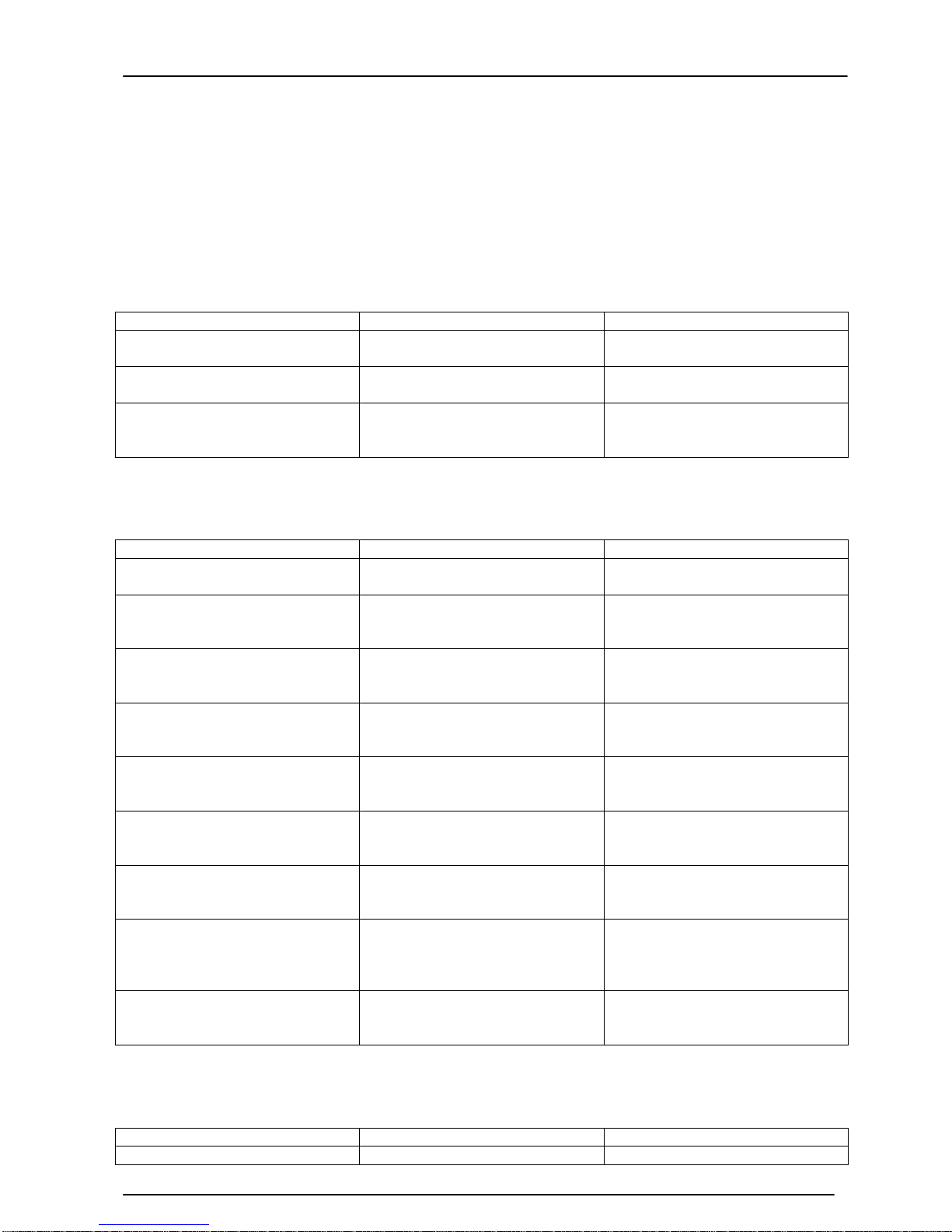
This section contai n s inf ormation which may solve simple operational problems you
may encounter. If you are unable to solve the problem or experience any problems with
the assembly or operation of the instrument contact Pulsar Instruments Plc your local
representative for further assistance
Basics
Symptom
Possible Cause
Possible Remedy
The instrument does n o t
switch on
The batteries are not fitted
Fit new batteries and switch
on
The batteries are flat or very
low
Fit new batteries and switch
on
The batteries are not correctly
fitted
Remove the batteries and
check the polarity of the
batteries
Calibration
Symptom
Possible Cause
Possible Remedy
The calibration fails: Too Low
The Acoustic Calibrator is not
switched on
Switch on the Acoustic
Calibrator and retry
The Acoustic Calibrator is not
fitted correctly
Check that the Acoustic
Calibrator is fitted according to
the instructions supplied.
The Preamplifer is not fitted
correctly. Class 1 Instruments
only
For Class 1 Instruments, refer
to page 15 for details of fitting
the preamplifier.
The microphone capsule is
loose or not fitted
Check that the microphone
capsule is tight and fitted
correctly
Calibration level set to a
different level
Set the calibration level to the
value provided by the Acoustic
Calibrator. See page 38
The Microphone may be
damaged
Contact Pulsar Instruments Plc
or your local representative for
assistance
The calibration fails: Too High The Acoustic Calibrator is set
to a higher level than the
expected level
Set the Acoustic Calibrator to
the correct level
The calibration fails: Unstable
The background noise level is
within 15dB of the calibration
level
Move to a location where the
background noise level is
more than 15dB below the
calibration level
The Microphone may be
damaged
Contact Pulsar Instruments Plc
your local representative for
assistance
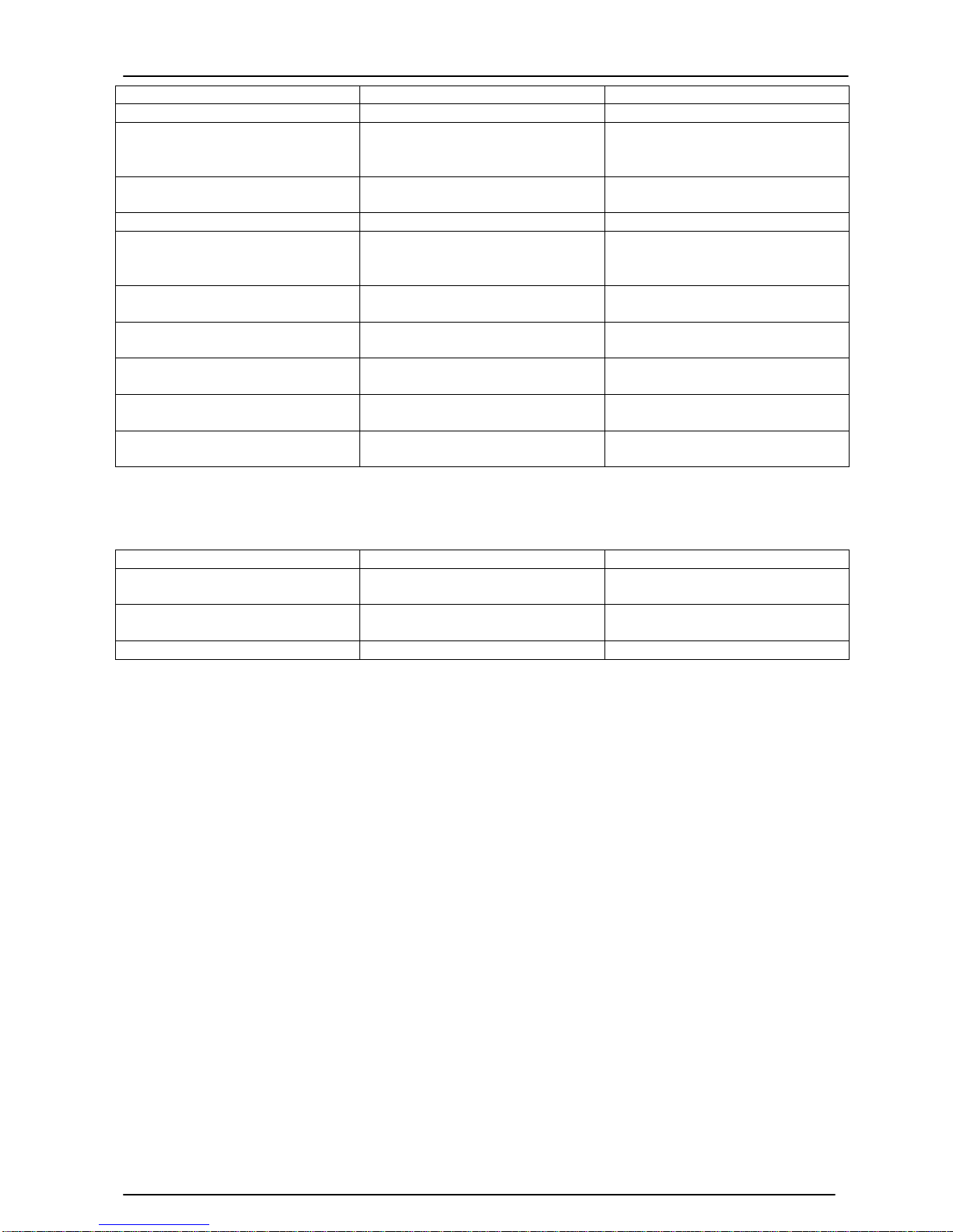
Measurements & Settings
Symptom
Possible Cause
Possible Remedy
No measurements have been
Memory is full.
Check the available memory.
Page 55
Model 90 Quantifier Sound Level Meter
Page 55
stored
See page 48
The measurement was reset
Restart the measurement
In 1:1 or 1:3 Octave Band
Mode, the filters do not
automatically sweep
The Run Duration has been set
to Manual.
Select a Preset Run Duration
The measurements are not
aligned with the clock
The Auto-Synchronise function
is switched off
Switch on the AutoSynchronise function
Instrument has selected
Impulse Time w eighting
L
Ieqt
User Metric may have
been selected
Select SEL User Metric and
change Time Weighting
required
Overload symbol is shown
The noise level is too high fo r
the current ran g e
Select a higher measurement
range
Under Range symbol is shown
The noise level is too low for
the current range
Select a lower measurement
range.
The measurement stops after
a set time
The Run Duration has been set
to a preset value.
Select the Manual Run
Duration
The Run Duration has been set
to the User Defined value.
Select the Manual Run
Duration
The measurement does not
stop as expected
The Run Duration has been set
to Manual
Select a preset Run Duration
Downloading Measurements
Symptom
Possible Cause
Possible Remedy
Measurements cannot be
downloaded
No measurements have been
stored
Repeat Measur em en t
Instrument is not connected to
PC
Connect the USB Cable and
retry.
Batteries are too low
Replace batteries
Page 56

Model 90 Quantifier Sound Level Meter
Page 56
Appendix 1 Specifications
Instrument Versions
MODEL 91 Class 1
MODEL 92 Class 2
MODEL 93 Class 1 with 1:1 Octave Band Filters
MODEL 94 Class 2 with 1:1 Octave Band Filters
MODEL 95 Class 1 with 1:1 & 1:3 Octave Band Filters
MODEL 96 Class 2 with 1:1 & 1:3 Octave Band Filters
Applicable Standards
Sound Level Meter
IEC 61672-1:2002 Class 1 or 2 Group X
IEC 60651:1979 Class 1 I or Class 2 I
IEC 60804:1985 Class 1 or Class 2
ANSI S1.4 with NK:70 Random Incidence Adaptor Fitted
1:1 & 1:3 Octave Band Filters (where fitted)
IEC 61260 Class 1
Microphone
Class 1 MK:224 pre-polarized Free-field ½" Condenser
Class 2 MK:216 pre-polarized Free-field ½" Condenser
Random Incidence to ANSI S1.4 with NK:70 Adaptor
Capacitance 18pF
Microphone Preamplifier
Class 1 MV:200D Removable Preamplifier
Class 2 MV:200D Integral Preamplifier
Extension cables
MEC2 2m
MEC5 5m
MEC10 10m
MEC15 15m
MEC20 20m
MEC25 25m
Time Weightings
‘F‘ (Fast) to IEC 61672-1:2002 Class 1 or 2 Group X
‘S' (Slow) to IEC 61672-1:2002 Class 1 or 2 Group X
‘I' (Impulse) to IEC 61672-1:2002 Class 1 or 2 Group X
Frequency Weightings
Channel 1 ‘A', ‘C' or ‘Z'
Channel 2 ‘C' for Peak
Z weighting is a flat frequency response of 8Hz – 20kHz ±1.5dB excluding microphone
response. When either 1:1 or 1:3 Octave Band filters are selected the ‘Z' weighting is
used.
Page 57

Model 90 Quantifier Sound Level Meter
Page 57
Amplitude Weighting
Q=3 (True Energy Integration)
Measurement Range
Broadband 21dB(A) to 140dB(A) Class 1
25dB(A) to 140dB(A) Class 2
143dB(C) Peak (70 to 140dB Range)
1:1 Octave Band Filters
19dB(Z) to 140dB(Z)
1:3 Octave Band Filters
14dB(Z) to 140dB(Z)
Range Steps
10-80, 20-90, 30-100, 40-110, 50-120, 60-130, 70-140
Noise Floor (Typical)
Broadband 18dB(A) Class 1, 20dB(A) Class 2
1:1 Octave Band Filters
12dB(Z) @ 1kHz 1:1 Octave Band
1:3 Octave Band Filters
7dB(Z) @ 1kHz 1:3 Octave Band
Available Measurements
The following metrics can be displayed for a recorded session and stored:
Broadband Mode
L
CPeak
L
AF,LAS,LAI,LCF,LCS,LCI,LZF,LZS
or LZI (not stored)
L
AFmax,LASmax,LAImax,LCFmax,LCSmax,LCImax,LZFmax,LZSmax
or L
ZImax
L
AFmin,LASmin,LAImin,LCFmin,LCSmin,LCImin,LZFmin,LZSmin
or L
ZImin
L
Aeq,LCeq
, or LZeq
L
AE,LCE
,or LZE,L
AIeq,LCIeq
, or L
ZIeq
, L
AFTeq
L
0.1
to L
99.9
(five simultaneous user-selected values available)
Run time
Date and time
1 second Short L
eq
Noise Profile
The Ln data is calculated from the Sound Level data and is Time Weighted according to
the selected Time Weighting.
Filter mode
1:1 or 1:3 filter sel ect ed
Selected frequency
Filtered L
ZS,LZF
or LZI (not stored)
Filtered L
Zeq
(stored)
L
Aeq
, L
Ceq
, L
Zeq
(stored)
Run time
Date and time
Page 58

Model 90 Quantifier Sound Level Meter
Page 58
Frequency Bands (Nominal Frequencies)
1:1 Octave Band
31Hz, 63Hz, 125Hz, 250Hz, 500Hz, 1kHz, 2kHz, 4kHz, 8kHz, 16kHz
1:3 Octave Band
25Hz, 31Hz, 40Hz, 50Hz, 63Hz, 80Hz, 100Hz, 125Hz, 160Hz, 200Hz, 250Hz,
315Hz, 400Hz, 500Hz, 630Hz, 800Hz, 1kHz, 1.25kHz, 1.6kHz, 2kHz, 3,15kHz,
4kHz, 5kHz, 6.3kHz, 8kHz, 10kHz, 12.5kHz, 16kHz
20Hz & 20kHz with MO:800/6 Factory Option
Memory
16Mbit memory allowing up to:
1300 broadband measurements
770 1:1 octave measurements
330 1:3 octave measurements
For example, broadband mode allows 12 days of 15 minute measurements
to be stored.
Calibration records are automatically stored in the instrument memory.
Noise Profile
Short Leq (L
Aeq,LCeq
, or L
Zeq
).
Up to 11 days at 1 second acquisition
Automatic Measurements
The unit can be set to record and store data over fixed times of
1 minute 5 minutes
10 minutes 15 minutes
30 minutes 1 hour
8 hours 12 hours
or a user defined period
Automatic Repeat From 2 to 999 measurements (broadband mode only)
Auto-synchronise to the clock.
Display
Matrix LCD with backlight & Quasi Analogue Bar Graph
Selected measurement parameter with level
Warnings for Overload, Under Range and
Low Battery
Time & Frequency Weighting
Elapsed measurement time
Real time short Leq (broadband mode)
Graphical 1:1 and 1:3 Octave Band (recall mode only)
Recalled stored measurements
Measurement Range
Weight
450 gms
Dimensions
340mm x 75mm x 25mm
Page 59

Model 90 Quantifier Sound Level Meter
Page 59
Batteries
2 x 1.5v Alkaline LR6/AA
Battery Life
Broadband Typically >30 hours
Filter Mode Typically >20 hours
Battery voltage is continuously monitored and warning is given on display of impending
low battery condition. When batteries approach end of life the unit will store any data
required and switch off automatically.
Environmental
Temperature
Operating -10
o
C to +50oC
Storage -20
o
C to +60oC
Humidity Up to 95% RH Non Condensing
External Co nnections
Data Output USB Type B Socket
Multi-pin Expansion Socket
Output Cabl e s
Standard DC80 USB Cable (supplied as standard)
Optional ZL:811 Power Adaptor Cable for CU:195A Power Supply
ZL:812 AC Output Cable to Phono Plug
ZL:813 RS232 Output
ZL:814 Multi-IO Interface Cable
Software Support
Analyser for Windows
System Requirements
The Analyser for Windows requires the following:
Microsoft Windows 95 or later
6Mb of available hard-disk space for program files
CD-ROM Drive
VGA or higher resolution monitor, Sup er VGA Recom mended
Microsoft compatible mouse or pointing device
9 Pin RS232 (Serial) Port
PC specification
Minimum: PII 266 MHz
Recommended: PIII 500 MHz
Factory Options
MO:800/1 Upgrade from Class 2 to Class 1
MO:800/2 Upgrade from Broadband to 1:1 Octave Band Filters
Page 60

Model 90 Quantifier Sound Level Meter
Page 60
MO:800/3 Upgrade from Broadband to 1:1 & 1:3 Octave Band Filters
MO:800/4 Upgrade from 1:1 to 1:1 & 1:3 Octave Band Filters
MO:800/5 Remote Preamplifier for Class 2 Instruments
MO:800/6 20Hz & 20kHz 1:3 Octave Band Filters
Electromagnetic Performance
EN 55022:1994
EN 61000-4-2:1995
EN 61000-4-3:1996 80MHz - 1GHz
EN 61000-4-3:1996 25MHz - 80MHz
EN 50204:1995 900MHz
EN 61000-4-8:1994 50Hz
Page 61
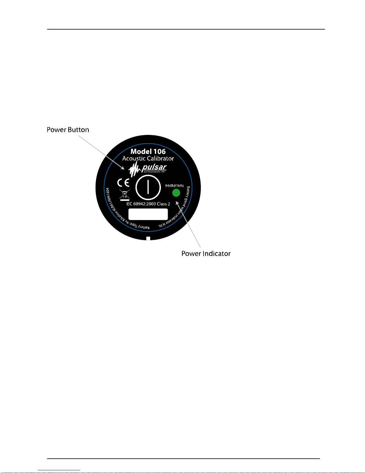
Model 90 Quantifier Sound Level Meter
Page 61
Model 105 & 106 Acoustic Calibrators
Operation.
Switching on the Calibrator
Press the Power Button on the end of the Calibrator to switch the unit on. The Indicator
will illuminate to show that the unit is operating.
The calibrator will automatically switch off after 5 minutes to preserve battery power.
To switch off the calibrator manually, press the power button again and the indicator
will extinguish to show that the unit is switched off.
Permanent-on Mode
For some applications there may be a need to have the calibrator switched on
continuously. To allow for this, the calibrator can be turned on by pressing and holding
the power button for three seconds.
Release the button and the indicator will flash to show that the unit is in permanent-on
mode. Press the power button to switch off the calibrator.
Page 62

Model 90 Quantifier Sound Level Meter
Page 62
Calibrating a Sound Level Meter.
Push the microphone of t he Sound Level Meter i n t o t he cavity at the end of the
calibrator. Ensure the microphone is fully inserted into the cavity and is past the ‘O’ ring
seals. The microphone should be parallel to the body of the calibrator. Also ensure that
the small bleed-hole next to the microphone cavity is not blocked as this could cause
damage to the microphone.
Most modern Sound Level Meters have electronic calibration with the level adjusted
automatically. Adjust the Sound Level Meter to the correct level where applicable.
When correcting the value generated by the calibrator a correction for the type of
microphone capsule may need to be applied (see Appendix 2)
Background Noise
In order for the calibrator to operate as intended, the ambient acoustic noise level
should be no greater than 80dBA.
Stabilisation
In order for the sound pressure level and frequency to stabilise after switching the
calibrator on when coupled to a microphone, a period of at least 3 seconds should be
allowed before performing a calibration.
Page 63
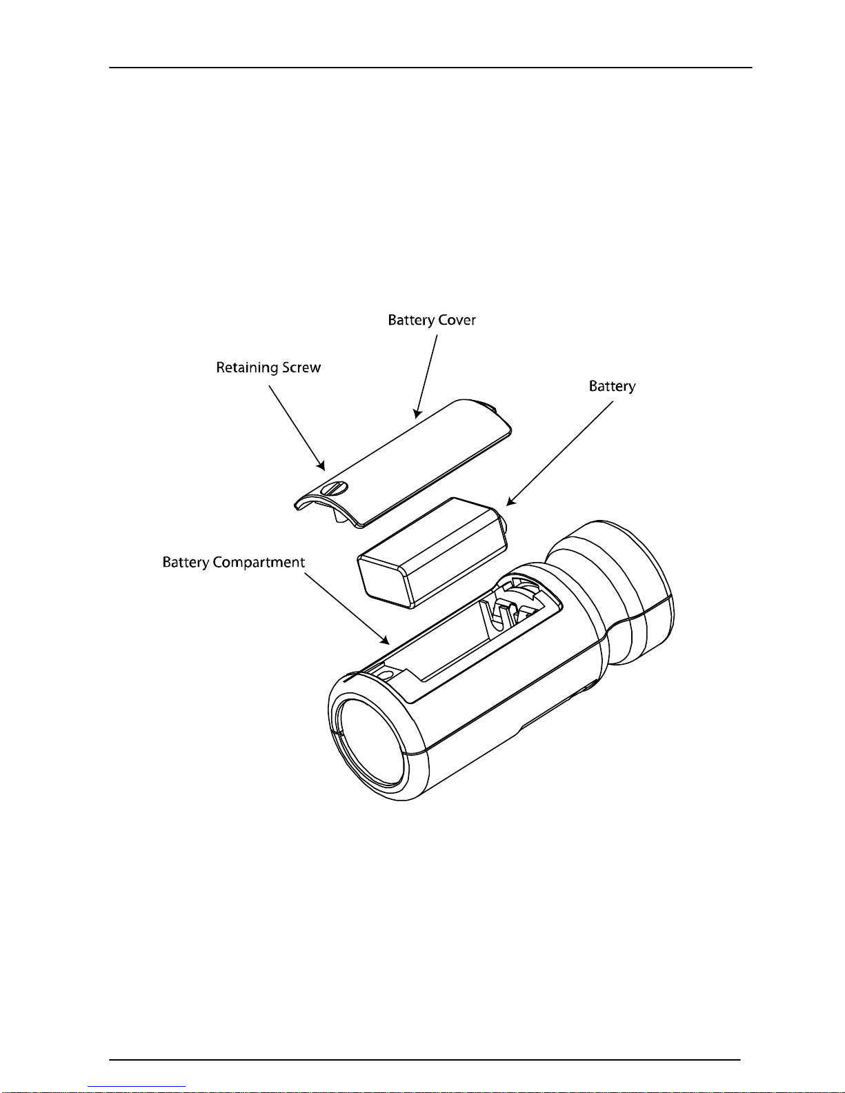
Model 90 Quantifier Sound Level Meter
Page 63
Changing the Battery
The Model 105 & Model 106 acoustic calibrators use a single 9v alkaline battery. This
type of battery is known as 6F22 or NEDA 1604. It is also commonly known as PP3.
1. Unscrew the screw holding the battery cover on, using a coin.
2. The battery, type 6F22 (PP3) can now be eased out of its holder and replaced.
The battery should be eased out terminal side first by pushing against the spring
at the other end. Ensure that the battery is inserted with the correct polarity
with the negative terminal at the contact with the larger cutout.
Battery type.
The battery should be an alkaline battery, not an ordinary dry cell. The battery is 9
volts when new and will operate the calibrator down to 6.4 volts. When the battery
voltage is below 6.6 volts but above 6.4 volts, the power LED will flash to indicate that
the battery voltage is low. When the battery voltage is below 6.4 volts the calibrator
will not turn on. A discharged battery may allow switch-on but will soon drop in voltage
and indicate low battery or switch off.
Page 64

Model 90 Quantifier Sound Level Meter
Page 64
Specification.
Frequency 1kHz ± 1%
Sound Level 94dB re 20μPa
Standardisation Model 105 - IEC 60942:2003 Class 2
Model 106 - IEC 60942:2003 Class 1
Distortion Less than 2%
Operating Humidity 25 to 90% Relative Humidity
Operating Static Pressure 65 kPa to 108kPa
Operating Temperature -10
o
C to +50oC
Storing Temperature -20
o
C to +60oC
Effective Volume 6.19 cm
3
± 0.2 cm3
Cavity Diameter 0.525 inch
Battery 1 x 9v 6F22 (Neda 1604)
Battery Life Approx 15 Hours Continuous Use
Battery Voltage 9v Nominal (10v Maximum, 6.4v Minimum)
Weight with Battery 185g
Dimensions 135mm x Ø48mm
Page 65

Model 90 Quantifier Sound Level Meter
Page 65
Technical Information
The normal mode of operation of the calibrator is with the unit switched on.
When the LED indicates the unit is switched on this produces the greatest radio
frequency emissions.
The calibrator continues to function after exposure to contact discharges up to 4kV and
air discharges up to 8kV, for both positive and negative voltages relative to earth
ground.
The calibrator conforms to IEC 60942:2003 for a modulated root-mean-square
electromagnetic field strength of 10 V/m.
The maximum susceptibility to power and radio frequency fields is with the cavity facing
away from the emitter with the battery compartment facing the table, the antenna
polarisation horizontal and the calibrator switched on.
Page 66

Model 90 Quantifier Sound Level Meter
Page 66
Free Field Correction
When calibrating a microphone which is to be used for free field measurements, a small
correction may be necessary to compensate for the difference between the
microphone's free field response at 'zero degrees' or 'head-on' incidence and the
pressure level generated by the calibrator.
The correction is typically -0.3dB for ½ inch microphones (making the effective
calibration level 93.7dB).
The table below shows the correction values for the standard microphones of Pulsar
Instruments Plc.
Calibration corrections are listed below for the Pulsar Instruments Plc½" Capsules and
three microphone capsules commonly used in Calibration Laboratories:
Microphone Correction Values
Microphone Type Calibration Correction Effective Calibration Level
MK:202 -0.3dB 93.7 dB
MK:215 -0.3dB 93.7 dB
MK:216 -0.3dB 93.7 dB
MK:226 -0.3dB 93.7 dB
MK:224 -0.3dB 93.7 dB
B&K 4134 0dB 94.0 dB
B&K 4180 0dB 94.0 dB
B&K 4192 0dB 94.0 dB
Example
An example of the procedure used to calculate the value for an MK:224 microphone is
shown below :
Level = 94.0dB + Microphone Correction
Level = 94.0dB + ( -0.3dB)
Level = 93.7dB
Different microphones will have different correction values. Please check the operation
manual for the Sound Level Meter or microphone concerned for details.
Page 67
Model 90 Quantifier Sound Level Meter
Page 67
Appendix 3 Software Installation
The MODEL 90 Series are supplied with the Analyser software on a CD-ROM.
Analyser is suitable for PC’s running Microsoft Windows 95 or later, including
WindowsXP and Windows2000. Analyser is supplied on CD-ROM, with a full installation
program, and comprehensive on line help, which gives details of the options and
functions of the software, along with details of the calculations used in the Hearing
Protector Selection Report.
Please note that for PC's running Windows 95, 98 and 98SE, the Analyser
software may need to install additional components to enable the database to
function correctly. These components are included with the installation
program.
Please also note that full administrator access may be required to install the
Analyser software under WindowsXP, Windows2000 or WindowsNT. Contact
your system adminstrator for further details.
To install the software, insert the CD-ROM into a CD-ROM drive on the PC. The
installation program should automatically start.
If the installation program does not automatically start run D:\setup.exe where D is the
drive letter of the CD-ROM drive on the PC.
System Requirements
The Analyser for Windows requires the following:
Microsoft Windows95, Windows 98, Windows 98 Second Edition, Windows ME, Windows
NT Workstation 4.0 with service pack 6, Windows 2000 Professional with service pack
2, Windows XP Home Edition or Professional
Internet access for downloading software updates
6Mb of available hard disk space for program files
64Mb RAM (128Mb recommended)
CD-ROM Drive for Installation
VGA or higher resolution monitor, Sup er VGA Recom mended
Microsoft compatible mouse or pointing device
9 Pin RS232 (Serial) Port or USB Connection
Installation Requirements
Pulsar Instruments Plcaccepts no responsibility for the installation of the Analyser
software where the system requirements are not fully met and where the user does not
have the correct configuration or access rights to enable the software to install
correctly.
Microsoft® is a registered trademark of the Microsoft Corporation. Windows 95
TM
,
Windows98
TM
, Windows ME
TM
and Windows XP
TM
are registered trademarks of the
Microsoft Corporation.
Page 68

Model 90 Quantifier Sound Level Meter
Page 68
Appendix 4 Configuring the instrument from the software
The configuration of the instrument can be set from within the Analyser software.
Different configurations can be saved and loaded into the instrument to suit different
measurement applications and standards. The following parameters can be set from
within the Analyser software:
• Measurement Mode
• Run Duration
• Time Weighting
• Frequency Weighting
• Measurement Range
• User Metric
• Measurement Auto Synchronisation
• Measurement Auto Repeat
• Ln values
• Remote Control of the S ou n d Level Meter via Modem (GSM or PSTN)
For full details, please refer to the Analyser software help.
Page 69
Model 90 Quantifier Sound Level Meter
Page 69
Appendix 5 CE Certificate of Conformity
Pulsar Instruments Plc Hunmanby UK
CE Certificate of Conformity
Manufacturer: Pulsar Instruments Plc
Acoustic House, Bridlington Road
Hunmanby, North Yorkshire, YO14 0PH
United Kingdom
Telephone +44 1723 518011
Equipment Description
The following equipment manufactured after 1
st
January 2004:
Model 91A Sound Level Meter
Model 92A Sound Level Meter
Model 93A Sound Level Meter
Model 94A Sound Level Meter
Model 95A Sound Level Meter
Model 96A Sound Level Meter
Along with their standard accessories
According to EMC Directives 89/336/EEC and 93/98/EEC
meet the following standards
EN 50081-1 (1992)
Generic emission standard for residential, commercial and light industry
EN 50082-1
RF immunity implies that sound level indications will not be affected by more than
"0.5dB at a background level of 74dB(A) or less.
Signed Dated 1
st
March 2004
S. O=Rourke
Director
Page 70

Model 90 Sound Level Meter User Manual
Page 70
Guarantee
Pulsar Instruments Plc offers a 12 month guarantee on all of their units. This covers all
parts and labour excepting only damage caused by the user. Because of the unique
fragility of microphones, only internal short or open circuits are accepted as faults and
not accident damage. The guarantee requires the user to return the unit to their
nearest authorised Pulsar Instruments Plc Agent. This guarantee is in addition to any
statutory rights in your country.
Pulsar Instruments Offices
The addresses given below are the Pulsar Instruments Plc offices. Pulsar Instruments
Plc also have approved distributors and agents is many countries worldwide. For details
of your local representative, please contact Pulsar Instruments Plc at the address
below.
Contact details for Pulsar Instruments Plc authorised distributors and agents are also
available from the Internet Web site at the address shown below.
The addresses given below are the Pulsar Instruments Plc offices. Pulsar Instruments
Plc also have approved distributors and agents is many countries worldwide. For details
of your local representative, please contact Pulsar Instruments Plc at the address
below. Contact details for Pulsar Instruments authorised distributors and agents are
also available from the Internet Web site at the address shown below.
Pulsar Instruments Plc
The Evron Centre
John Street
Filey
North Yorkshire
United Kingdom
YO14 9DQ
Telephone: 01723 518011
Fax: 01723 518043
e-mail: [email protected]
Web Site: www.pulsarinstruments.com
 Loading...