

Pulsar 79214 1 HP Owner's Manual

BOOSTER PUMP
O W N E R ‘ S M A N U A L
INSTALLATION, OPERATION & PARTS
115/230V/60Hz/1Ph - 79214 1 HP Model
This manual should be given to the user of this pump.
© 2010 Arch Chemicals, Inc.
1200 Lower River Road, Charleston, TN 37310
1-800-310-TECH(8324)
Pulsar® is a registered trademarks of Arch Chemicals Inc. Plasto-Joint Stik® is a registered trademark of La-Co Industries,
Inc. Teflon® is a registered trademark of E.I. Du Pont De Nemours and Company Corporation. Unless noted, names and
brands of others that may be used in this document are not used to indicate an affiliation or endorsement between the
proprietors of these names and brands and Pentair Water Pool and Spa, Inc. Those names and brands may be the
trademarks or registered trademarks of those parties or others.
05-26-10 359608 (Rev. A)
*359608*
2
READ THIS MANUAL
CAREFULLY!
The PULSAR SYSTEM Series pump:
Table of Contents
Safety Instructions ......................................................2
Installation ................................................................3-4
Electrical...................................................................4-6
Operation.....................................................................6
Storage/Winterizing ..................................................6-7
Pump Service ...........................................................7-8
Troubleshooting Guide.................................................9
Repair Parts List ........................................................10
Warranty ....................................................................11
READ AND
FOLLOW SAFETY
INSTRUCTIONS!
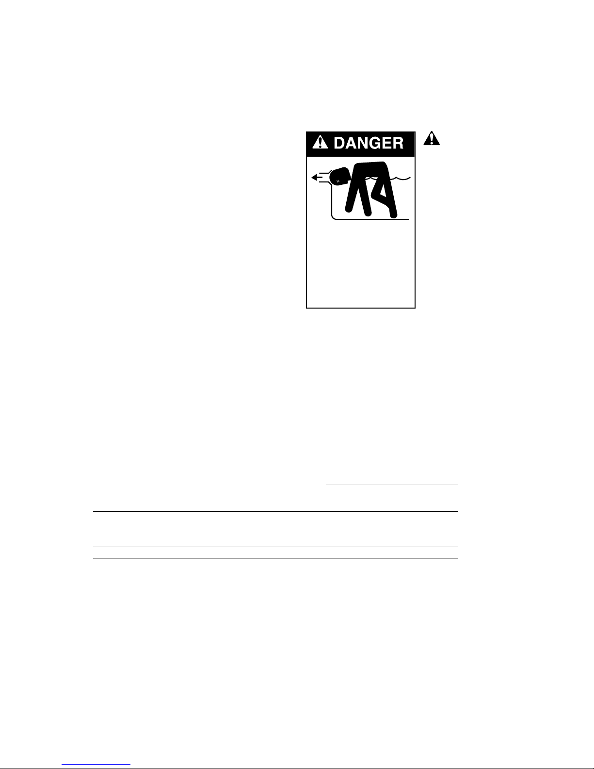
This is the safety alert symbol. When you see this
symbol on your system or in this manual, look for
one of the following signal words and be alert to the
potential for personal injury.
warns about hazards that will cause death,
serious personal injury, or major property damage if
ignored.
warns about hazards that can cause death,
serious personal injury, or major property damage if
ignored.
warns about hazards that will or can cause
minor personal injury or property damage if ignored.
NOTICE indicates special instructions not related to
hazards.
Carefully read and follow all safety instructions in
this manual and on equipment. Keep safety labels in
good condition; replace if missing or damaged.
Incorrectly installed or tested equipment
may fail, causing
severe injury or property damage.
Read and follow instructions in owner's manual when
installing and operating equipment. Have a trained pool
professional perform all pressure tests.
1. Do not connect system to a high pressure or city
water system.
2. Use equipment only in a pool or spa installation.
3. Trapped air in system can cause explosion. BE SURE
all air is out of system before operating or testing
equipment.
Before pressure testing, be sure to follow the safety
checks listed below:
• Check all clamps, bolts, lids, and system accessories
before testing.
• Release all air in system before testing.
• Tighten trap lids to 30 ft. lbs. (4.1 kg-m) torque for
testing.
• Water pressure for test must be less than 25 PSI (7.5
kg/cm
2
).
• Water Temperature for test must be less than 100oF.
(38oC).
• Limit test to 24 hours. After test, visually check
system to be sure it is ready for operation. Remove
trap lid and retighten hand tight only.
IMPORTANT SAFETY
INSTRUCTIONS
Always follow basic safety precautions with this
equipment, including the following.
To reduce the risk of injury, do not
permit children to use this product unless they are
closely supervised at all times.
This pump is for use with permanently
installed pools and may also be used with hot tubs
and spas if so marked. Do not use with storable
pools. A permanently installed pool is constructed in
or on the ground or in a building such that it cannot
be readily disassembled for storage. A storable pool
is constructed so that it may be readily disassembled
for storage and reassembled to its original integrity.
SAVE THESE
INSTRUCTIONS
3
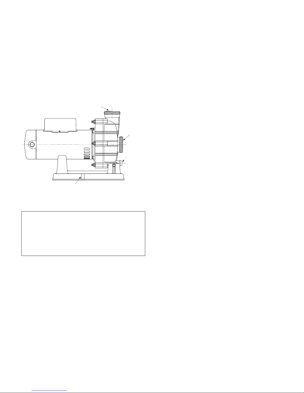
INSTALLATION
Only qualified, licensed personnel should install
pump and wiring.
Pump mount must:
Be solid - Level - Rigid - Vibration free. (To reduce
vibration and pipe stress, bolt pump to mount.)
Install pump with suction port below water level (flooded
suction) only. Pump does not lift water.
Allow use of short, direct suction pipe (To reduce friction
losses).
Allow for gate valves in suction and discharge piping.
Have adequate floor drainage to prevent flooding.
Be protected from excess moisture.
Allow adequate access for servicing pump and piping.
NOTICE: When connecting threaded pipe directly to
pump, use Teflon tape or Plasto-Joint Stik to seal
connections. Do not use pipe dope; pipe dope causes
cracking in some plastics and may damage components
in piping system.
When connecting threaded pipe to pump with union
half, use Teflon tape or Plasto-Joint Stik between pipe
and union adapter. Union collar to pump should be
assembled dry and hand-tight. Make sure O-ring is
seated in groove.
NOTICE: Pump suction and discharge connections
have molded in thread stops. DO NOT try to screw pipe
in beyond these stops.
Teflon Taping Instructions:
Use only new or clean PVC pipe fittings.
Wrap male pipe threads with one to two layers of Teflon
tape. Cover entire threaded portion of pipe.
Do not overtighten or tighten past thread stop in pump
port!
If leaks occur, remove pipe, clean off old tape, rewrap
with one to two additional layers of tape and remake the
connection.
NOTICE: Support all piping connected with pump!
Piping:
Use at least 1-1/2" (38mm) pipe (use 2"(51mm) pipe if
possible). Increase size if a long run is needed. When
using 1-1/2" pipe, connect to pump with 1-1/2" to 2" (38
to 51mm) reducing adapter.
To avoid strains on the pump, support both suction and
discharge pipes independently. Place these supports
near the pump.
To avoid a strain left by a gap at the last connection,
start all piping at the pump and run pipe away from the
pump.
To avoid airlocking, slope suction pipe slightly upward
toward the pump.
NOTICE: To prevent flooding when removing pump for
service, all flooded suction systems must have gate
valves in suction and discharge pipes.
Port threads:
Internal - 2" NPT for direct connection to pipe. External -
3" Buttress. Fits U11-200PS Union Collar for quick
disconnect pipe connection.
Order: Union Kit #42001-0402 (2" Union Halves).
n
Figure 1
NOTE: This booster pump is designed without a strainer.
However, a strainer that meets NSF 50 requirements can
be used with the pump.
Discharge
Port
Suctio
Port
Drain
Plug
Pump may be bolted to level
foundation or mounting bracket.
791 0394
4
Fittings:
Fittings restrict flow; for best efficiency use fewest
possible fittings.
Avoid fittings which could cause an air trap in suction
piping.
Pool and spa drains must conform to International
Association of Plumbing and Mechanical Officials
(IAPMO) standards.
Use only non-entrapping suction fittings and dual
suction outlets.
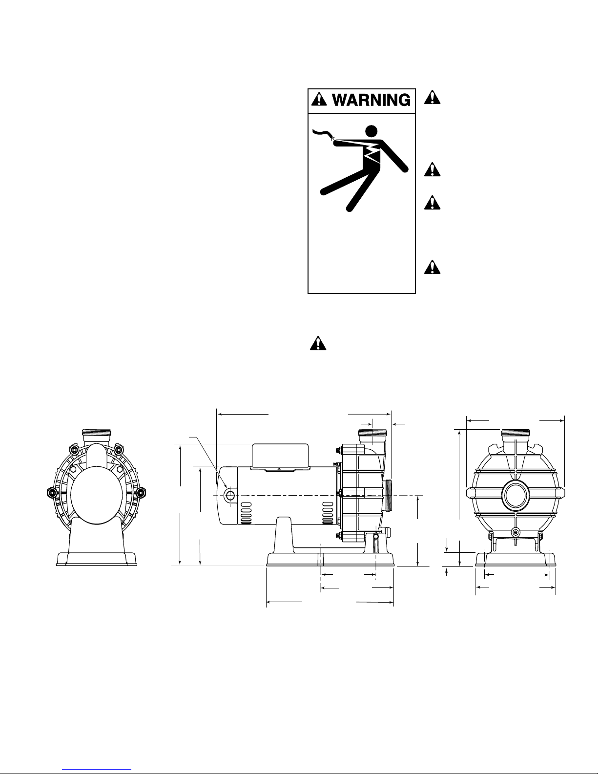
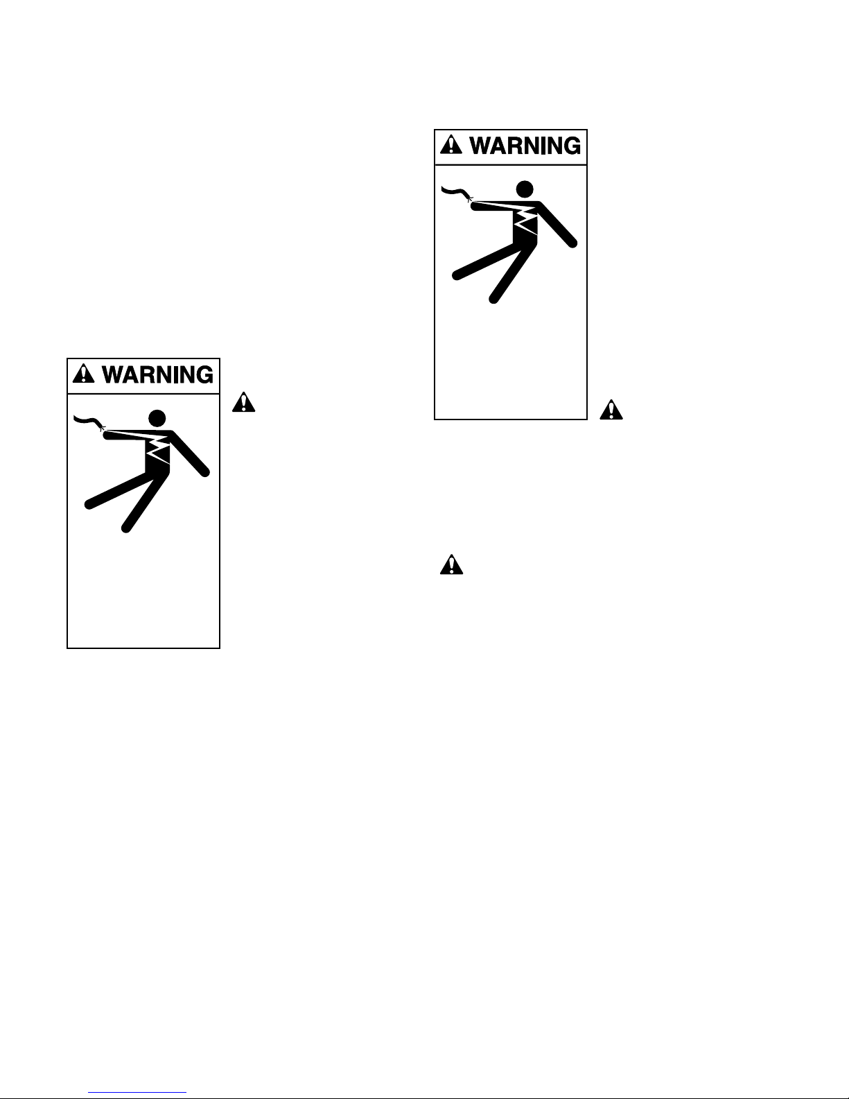
ELECTRICAL
Ground motor before
connecting to
electrical power supply.
Failure to ground motor
can cause severe or fatal
electrical shock hazard.
Do not ground to a
gas supply line.
To avoid dangerous or
fatal electrical shock,
turn OFF power to motor
before working on
electrical connections.
Ground Fault Circuit
Interrupter (GFCI)
tripping indicates an
electrical problem. If GFCI
trips and will not reset, have a qualified electrician
inspect and repair electrical system.
Exactly match supply voltage to motor
nameplate voltage. Incorrect voltage can cause
fire or seriously damage motor and voids warranty.
If in doubt consult a licensed electrician.
See Figure 2.
Hazardous voltage.
Can shock, burn,
or cause death.
Ground pump before
connecting to
power supply.
Figure 2 – Outline Dimensions in Inches (mm)
1/2-14 SPT
11-15/16
(303)
9-5/8
(244)
18-61/64 (481) Max
17-5/16 (440) Min
6 (152)
8 (203)
13-7/8 (352)
2-1/16 (52)
6-7/8
(175)
1-1/4
(32)
10-7/8 (276)
13-1/4
(337)
6-3/4 (171)
8-3/4 (222)
792 1094
5
Voltage
Voltage at motor must be not more than 10% above or
below motor nameplate rated voltage or motor may
overheat, causing overload tripping and reduced
component life. If voltage is less than 90% or more than
110% of rated voltage when motor is running at full
load, consult power company.
Grounding/Bonding
Install, ground, bond and wire motor according to local
or National Electrical Code requirements.
Permanently ground motor. Use green ground terminal
provided under motor canopy or access plate (See Fig.
3); use size and type wire required by code. Connect
motor ground terminal to electrical service ground.
Bond motor to pool structure. Use a solid copper
conductor, size No. 8 AWG (8.4 sq.mm) or larger. Run
wire from external bonding lug (see Fig. 3) to reinforcing
rod or mesh.
Connect a No. 8 AWG (8.4 sq.mm) solid copper
bonding wire to the pressure wire connector provided
on the motor housing and to all metal parts of the
swimming pool, spa, or hot tub and to all electrical
equipment, metal piping or conduit within 5 feet (1.5 m)
of the inside walls of swimming pool, spa, or hot tub.
Wiring
Pump must be permanently connected to circuit (see
Figure 4A and 4B); be sure no other lights or appliances
are on the same circuit. Match wire sizes to Table I
(Pg. 6).
NOTICE: To prevent dirt, rain, bugs, etc., from entering
motor when not wiring with conduit, be sure to seal wire
opening on end of motor.
Use Ground Fault Circuit Interrupter (GFCI) as master
on-off switch; it will sense a short circuit to ground and
disconnect power before it becomes dangerous to pool
users. Test according to maker’s instructions.
In case of power outage, check GFCI for tripping (which
will prevent normal water circulation). Reset if
necessary.
Risk of dangerous or fatal electrical shock.
Be sure that power to the motor circuit is off before
working on wiring, wiring connections, or motor. Reinstall the motor end cover and all other wiring covers
before turning on the power.
1. Turn off power.
2. Remove the motor end cover.
To Wire a Single Speed, Single Voltage Motor
There are two terminals labeled L1 and L2. Attach the
power leads to these terminals. Either wire may attach to
either terminal.
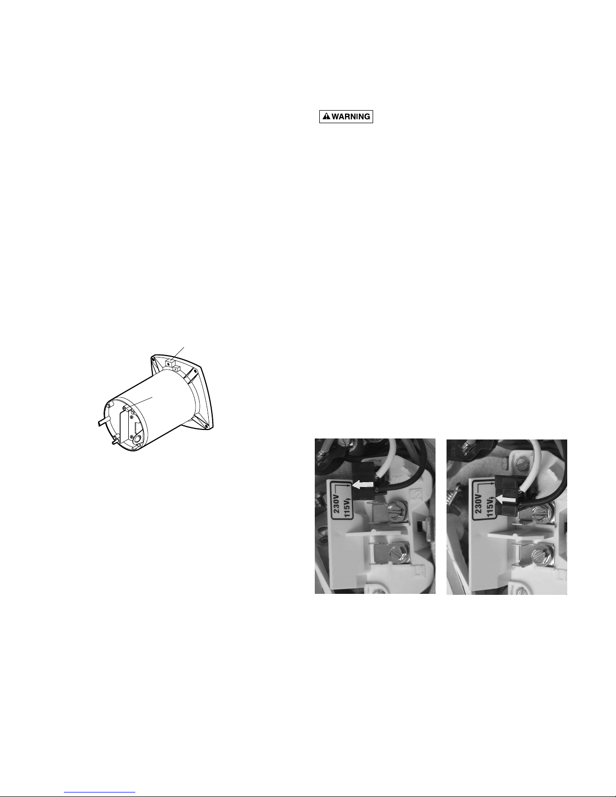
To Wire a Dual-Voltage Motor
Dual voltage motors have a plug to change from 230
volts (factory setting) to 115 volts.
1. If you have 230 volts motor supply voltage, confirm
that the plug is set for 230 volts. The arrow on the
plug will point to the 230 volt position. Note that plug
only connects with one prong in this position.
2. If you have 115 volt supply, pull the plug straight up
and place it on the two brass prongs as shown.
NOTE: Arrow is highlighted for clarity.
Figure 3 – Typical ground screw and bonding lug
locations.
Figure 4B Voltage Change
Plug Set for 115 Volts
Figure 4A -Voltage Change
Plug Set for 230 Volts
BONDING
LUG
GREEN
GROUND
SCREW
510 0993
6
OPERATION
NOTICE: NEVER run pump dry. Running pump dry
may damage seals, causing leakage and flooding.
Fill pump with water before starting motor.
Do not block pump
suction. To do so with
body may cause severe or
fatal injury. Small children
using pool must ALWAYS
have close adult
supervision.
Priming Pump
Release all air from filter
and piping system: see
filter owner’s manual.
In a flooded suction
system (water source
higher than pump), pump
will prime itself when
suction and discharge valves are opened.
Storage/Winterizing:
NOTICE: Allowing pump to freeze will damage pump
and void warranty!
NOTICE: Do not use anti-freeze solutions (except
propylene glycol) in your pool/spa system. Propylene
glycol is non-toxic and will not damage plastic system
components; other anti-freezes are highly toxic and may
damage plastic components in the system.
TABLE I - RECOMMENDED FUSING AND WIRING DATA
NOTICE: 79214 pumps use 60 Cycle current only.
(*) Time delay fuses are recommended instead of standard fuses in any motor circuit.
Hazardous suction.
Can trap hair or body
parts, causing severe
injury or death.
Do not block suction.
Do not operate system
with broken or missing
drain covers.
Serv. to Motor - Dist. in Ft. (M)
Motor Branch Fuse Max Load Voltage/ 0-100' 101-200' 201-300'
HP Rating Amps* Amps Hz/Phase (0-30) (30-60) (60-90)
79214 Model:
1 20/15 12.6/6.3 115/230/60/1 12(2)/14(2) 10(2)/14(2)1010(2)/14(2)
7
Drain all water from pump and piping when expecting
freezing temperatures or when storing pump for a long
time (see instructions below).
Keep motor dry and covered during storage.
To avoid condensation/corrosion problems, do not
cover pump with plastic.
For outdoor/unprotected installations:
1. Enclose entire system in a weatherproof enclosure.
2. To avoid condensation/corrosion damage, allow
ventilation; do not wrap system in plastic.
3. Use a 40% propylene glycol/60% water solution to
protect pump to -50°F (-46°C).
Draining Pump
1. Pump down water level
below all inlets to the pool.
To avoid dangerous or
fatal electrical shock
hazard, turn OFF power to
motor before draining
pump.
2. Cap inlet piping after
draining to keep water out
of the pipes.
3. To prevent pump from
freezing, drain the pump
body through the drain
fitting provided.
4. Be sure motor is kept dry
and covered.
Startup For Winterized Equipment
1. Remove any temporary weather protection placed
around system for shutdown.
2. Follow filter manufacturer’s instructions for
reactivation of the filter.
3. Inspect all electrical wiring for damage or
deterioration over the shutdown period. Have a
qualified serviceman repair wiring as needed.
4. Inspect and tighten all watertight connections.
5. Open all valves in suction and return piping.
6. Remove any winterizing plugs in piping system.
7. Drain all antifreeze from system.
8. Close all drain valves and replace all drain plugs in
piping system.
9. Prime pump according to instructions on Page 6.
PUMP SERVICE
Pump should only be
serviced by qualified
personnel.
Be sure to prime pump (Pg.
6) before starting.
1. STOP PUMP before
proceeding.
2. CLOSE GATE VALVES in
suction and discharge
pipes.
3. RELEASE ALL PRESSURE
from pump and piping
system.
To avoid dangerous or
fatal electrical shock
hazard, turn OFF power to motor before working on
pump or motor.
If shaft seal is worn or damaged, repair as follows:
Pump Dissasembly/Removing Old Seal
Disconnect power to pump motor.
Be sure gate valves on suction and return
piping are closed before starting work.
Release all pressure by opening all vents before
starting work.
1. Drain pump through drain fitting on bottom of pump
body.
2. Remove 6 nuts, lockwashers and flat washers
holding seal plate to pump body. Pull seal plate and
motor away from pump body. (You may have to
CAREFULLY use a screwdriver to separate body
from seal plate.)
3. Remove seven screws and washers holding diffuser
to seal plate. Remove diffuser.
4. Remove motor canopy. Being careful not to touch
capacitor terminals, loosen capacitor clamp and
move capacitor to one side.
5. Hold shaft with 7/16" open-end wrench on motor
shaft flats.
6. Unscrew impeller from shaft (turn counterclockwise
when facing it).
7. Remove four screws holding seal plate to motor.
Hazardous voltage.
Can shock, burn,
or cause death.
Disconnect power
before working
on pump or motor.
Hazardous voltage.
Can shock, burn,
or cause death.
Disconnect power
before working
on pump or motor.
8
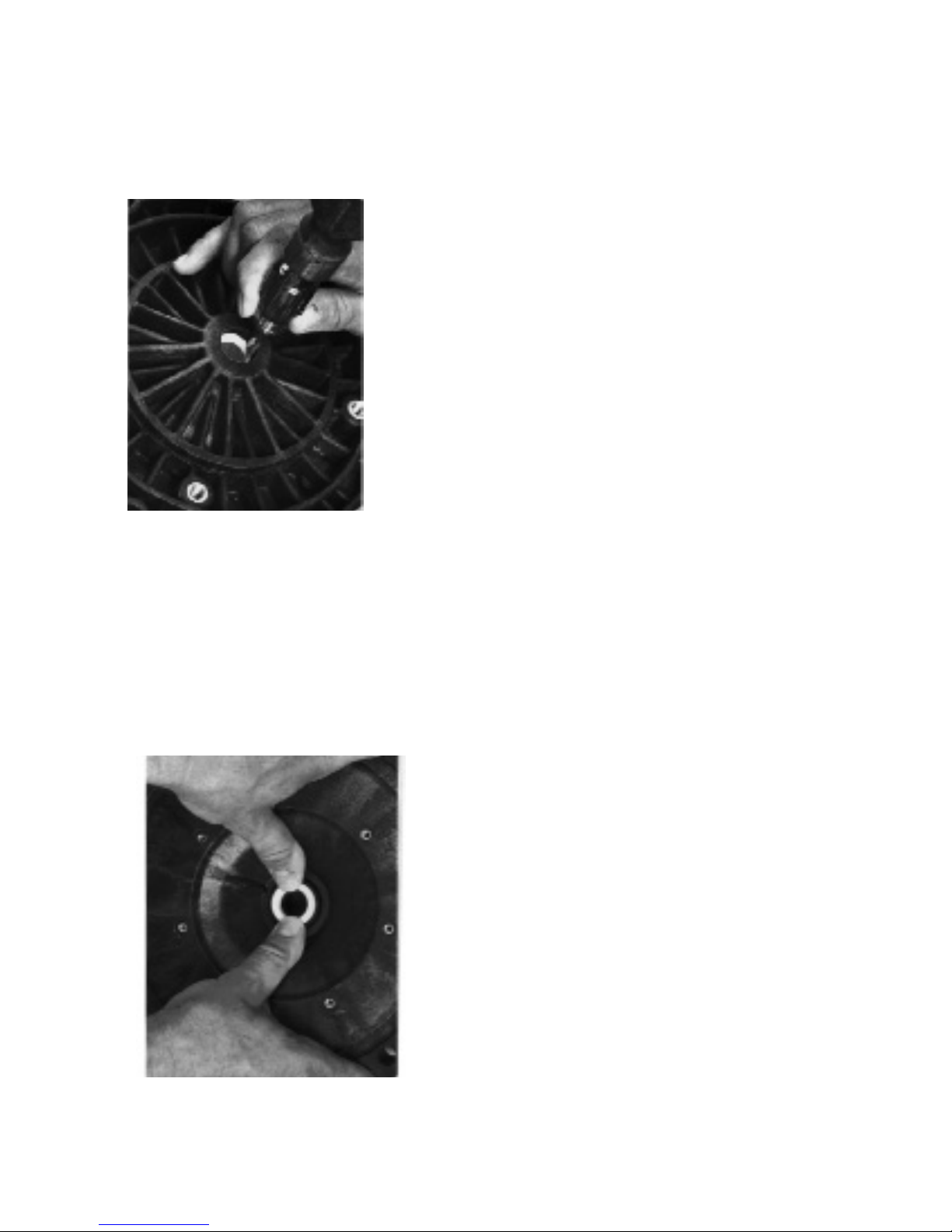
8. Place seal plate face down on flat surface and tap
out ceramic seat (Fig. 5).
9. Remove slinger from motor shaft and inspect for
damage or abrasion.
10. Clean seal cavity in seal plate and clean motor
shaft.
Pump Reassembly/Installing New Seal
1. Ceramic seal must be clean and free of dirt, grease,
dust, etc. Wet outer edge with small amount of
liquid detergent; press ceramic seal into seal plate
cavity firmly and squarely with finger pressure
(Fig. 6).
2. If ceramic seal will not seat properly, remove it,
place face up on bench and reclean cavity. Ceramic
seal should now seat properly.
3. If seal still will not seat properly, place a cardboard
washer over the polished face and use a piece of
3/4" (19mm) standard pipe for pressing purposes.
NOTICE: Be sure not to scratch or mar polished
surface or seal will leak.
4. Replace slinger on end of motor shaft so that
impeller sleeve will push it into position. If slinger
shows signs of wear or damage, replace it.
5. Remount seal plate on motor. Tighten bolts to 60-80
inch-lbs. (69-92 kg/cm) torque.
6. Apply a small amount of liquid detergent to inside
diameter of rotating half of seal.
7. Slide rotating seal member, polished carbon face
out, over impeller sleeve until rubber drive ring hits
back of impeller.
NOTICE: Be sure not to nick or scratch polished
seal face; seal will leak if face is damaged.
8. Screw impeller onto shaft (clockwise); this will
automatically locate seal in seal plate.
9. Mount diffuser on seal plate; tighten screws to 1014 inch-lbs. (11.2-16.1 kg/cm) torque.
10. Assemble motor and seal plate to pump body with
nuts, flat washers and lock washers. Torque nuts to
120-130 in-lbs. (138-150 kg/cm).
11. Prime pump according to instructions on Page 6.
Figure 5
Figure 6
 Loading...