

Pulsar 200 NS Owner's Manual


REV. 01, MAY 12
Foreword
Welcome to the Pulsar family!
You are now the proud owner of the next generation Pulsar 200 NS, India's No.1 sports bike. By
No.1 we are talking about unparalleled performance, superior technology and incredible market
leadership that Pulsar today enjoys. This makes the Pulsar you ride, unbeatable and unchallenged
both on and off the road.
Before you ride out, please read this Owner's Manual carefully and familiarize yourself with the
operating mechanism, controls and maintenance requirements of your Pulsar. This will ensure you a
safe and trouble free ownership experience.
To keep your bike in perfect running condition and deliver consistent performance, we have
specially programmed the periodic maintenance services which includes 3 free services and
subsequent paid services, as per the schedule contained in this booklet. We earnestly advise you
to avail all these services at any of our Bajaj Dealers or Authorised Service Centres, who are well
equipped with all necessary facilities / genuine parts / oil and trained manpower to ensure the best
care for your Pulsar. Your ‘Pulsar 200 NS’ comes with a warranty of 2 Years or 30,000 Kms
whichever occurs earlier from the date of sale. For details please refer to “Warranty : Scope &
Limits” given in this manual.
Should you require any additional information feel free to contact us on our toll free no.:
1800 233 2453 or e-mail us at: customerservice@bajajauto.co.in or visit the Bajaj Auto website
www.bajajauto.com
To be a part of the Pulsarmania, visit www.mypulsar.com and join the Pulsar fanpage on facebook:
www.facebook.com/mypulsar
Rev up, shift gears and enjoy the Pulsar experience…
SERVICE DEPARTMENT
BAJAJ AUTO LIMITED
Description
1. Technical Specifications 1
2. Identification Data 3
3. Location of Parts 4
4. Steering cum Ignition lock 6
5. Fuel Tank Cap / Fuel Tap 7
6. Speedometer Details 8
7. Speedometer Setting 10
8. Control Switches 12
9. Rear seat / Tool kit 14
10. Front Seat / Battery 15
11. Fitment of Front & Rear Seat 16
12. Removal & Fitment of Side Cover LH & RH 17
13. Daily Safety Checks 18
14. How to ride your Bike 19
15. Safe Riding Tips 23
16. Engine Oil 24
17. Wheels - Tube less Tyre 25
18. Battery 26
19. Engine Cooling System / Coolant 27
20. Periodic Maintenance Information 29
21. Brake Fluid 31
22. Periodic Maintenance & Lubrication Chart 32
23. Warranty Certificate 37
24. Warranty Scope & Limit 38
2 .
26. Non Use Maintenance & Service Coupons
5 Battery Warranty Card
Notice:
The description and illustration in this booklet
are not to be taken as binding on the
manufacturers. The essential features of the
type described and illustrated herein remaining
unaltered. Bajaj Auto Limited reserves the
right to carry out at any moment without
being obliged to bring this booklet upto-date
& to do modifications on the vehicle, parts or
accessories as may be convenient and
necessary.
Safety and Warning information :
Table of Contents
Caution : This indicates that a potential
hazard that could result in vehicle
damage. Follow the Advice provided with
the caution.
Warning : This indicates that a potential
hazard or injury to you or other persons &
to the vehicle can happen if advice
provided is not followed.

Engine : 4 Stroke, Single Cyl.
Bore x Stroke : 72.0 mm x 49.0 mm
Engine Displacement : 199.5 cc
Compression Ratio : 11 : 1
Idling Speed : 1350 ~ 1450 RPM
Max. Net Power : 23.5 PS at 9500 RPM
Max. Net Torque : 18.3 Nm at 8000 RPM
Ignition System : DC
Spark Plug : 3 Nos
Spark Plug Gap : 0.7 ~ 0.8 mm
Transmission : 6 speed constant
mesh
Gear Shifting Pattern : 1 Down 5 Up
Engine Lubrication : Pressurized oil supply
Engine Cooling : Water cooling
Starting Aid : Electric starter
Front Brake : Hydraulic Disc type
Rear Brake : Hydraulic Disc type
Fuel Tank Capacity
Full : 12 liters
Usable Reserve : 2.4 liters
Unusable Reserve : 0.2 liters
Dimensions :
Length : 2017 mm
Width : 804 mm
Height : 1195 mm
Wheel base : 1363 mm
Ground clearance : 167 mm
Tyre Size
Front : 100/80-17,52P tubeless
Rear : 130/70-17,61P tubeless
Tyre Pressure
2
Front : 1.75 kgf/cm (25 PSI)
2
Rear (Solo) : 2.00 kgf/cm (28 PSI)
2
Rear (with pillion) : 2.25 kgf/cm (32 PSI)
Technical Specifications
1
Note :
• All dimensions are under UNLADEN condition.
• Above information is subject to change without
any notice.
Electrical System : 12 Volts DC
Head Lamp : H4, 55/60W
Position Lamp : 3W (2 nos.)
Tail /Stop Lamp : LED type
Side Indicator lamp : 10W
Neutral Indicator : Green LED
Hi Beam Indicator : Blue LED
Turn Signal Indicator : Green LED
Side Stand Indicator : LED
Speedometer Lamp : LED
Rear No. Plate Lamp : 3W
Horn : 12V DC
Battery : 12V - 8 Ah VRLA
Vehicle Kerb Weight : 145 kg.
Gross Vehicle Weight : 275 kg.
(Including rider & pillion)
Max. Speed : 136 km/hr.
2
Technical Specifications
Identification Data
The Frame and Engine serial numbers are used to register the motorcycle. They are the unique
alpha-numeric codes to identify your particular vehicle from others of the same model and type.
Frame Number Location
On RH Side of Steering Tube
(Alpha-Numeric - 17 Digits)
Engine Number Location
On LH Side Crankcase Near Gear
Change Lever (Alpha-Numeric - 11 Digits)
3

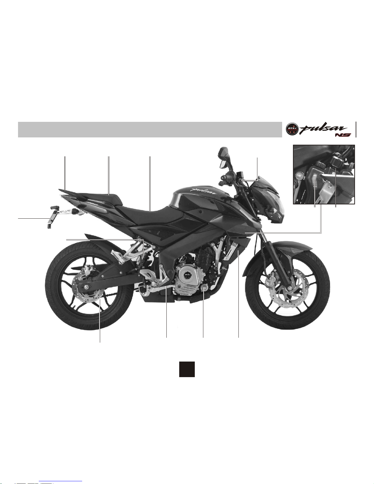
Location of Parts
Front Fork
Clutch Lever
Fuel Tank Cap
Manual Choke
Lever
Pillion
Foot
Rest
Side
Stand
Gear Change
Lever
Digital
Speedometer
Disc
Brake
LED
Tail
Lamp
4
OFF
ON
Location of Parts
Grab Handle Pillion Seat Rider Seat
Rear Disc Brake
Radiator
Coolant
Level
Indicator
Radiator
Expansion
Tank Cap
Rear Brake
Pedal
Paper oil
Filter
Front Brake Lever
Rear
Number
Plate
5
MAX
MIN
Nitrox Rear
Shock Absorber
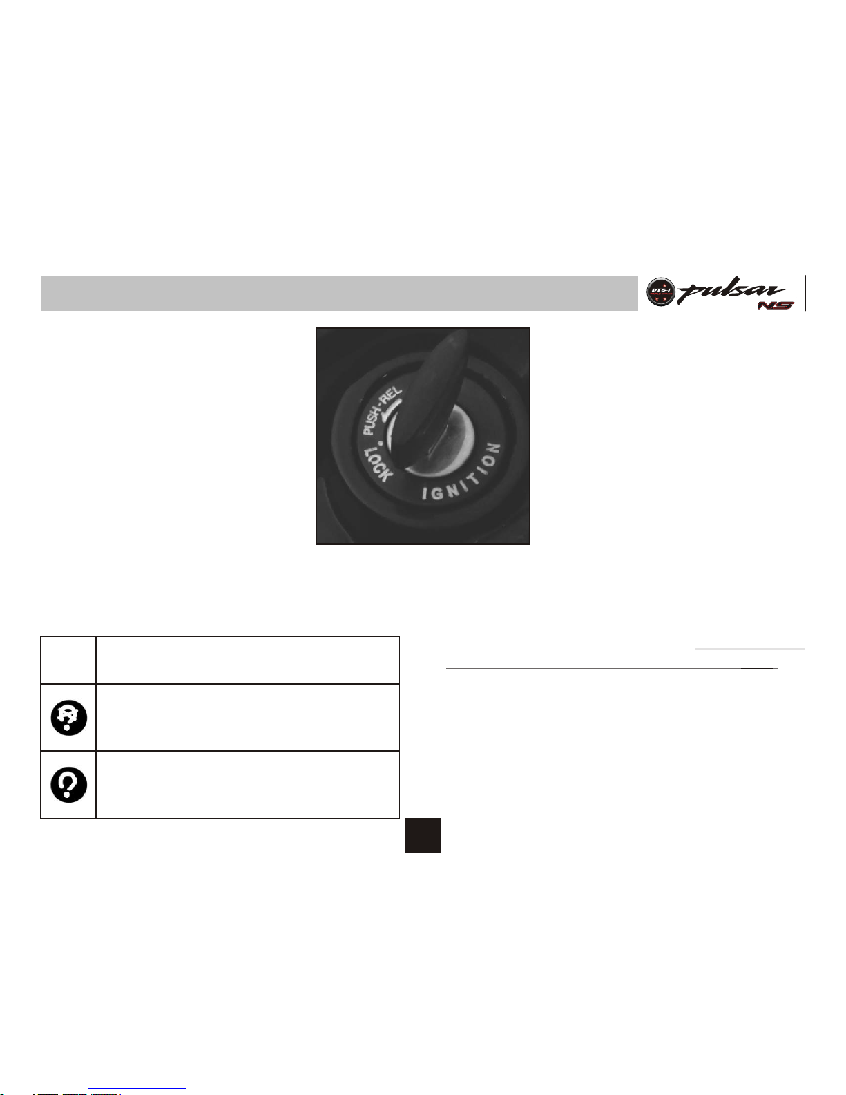
Steering cum Ignition Lock
To Lock the Steering : To lock the steering,
turn the handle bar to the left side. Push &
release the key. Turn the key to “LOCK”
position and remove the key. Steering lock
can be done on left handle position only.
To Unlock the Steering : To unlock steering,
insert the key in steering cum ignition lock &
turn it clockwise to “OFF” or “ON” position.
Key : A common key is used for ‘Steering
cum Ignition lock’, ‘Fuel tank cap’ & ‘Rear
Seat’.
Steering cum Ignition Lock :
It has three positions.
LOCK: Steering locked. Ignition OFF.
OFF: Steering unlock. Ignition OFF.
ON: Steering unlock. Ignition ON.
6
Fuel Tank Cap
• To open the fuel tank cap, open the flap.
Insert the key in the lock and turn it
clockwise and lift fuel tank cap.
• ‘Fuel Tank Cap’ gets locked when pushed
back into the place.
Fuel Tap
Fuel tap lever has following positions.
ON : When fuel level is above Reserve
position.
RES : When fuel level is below Reserve
position.
OFF : When fuel supply is to be cut off.
Fuel Tap
Fuel Tank Cap / Fuel Tap
Fuel Tank Cap
7
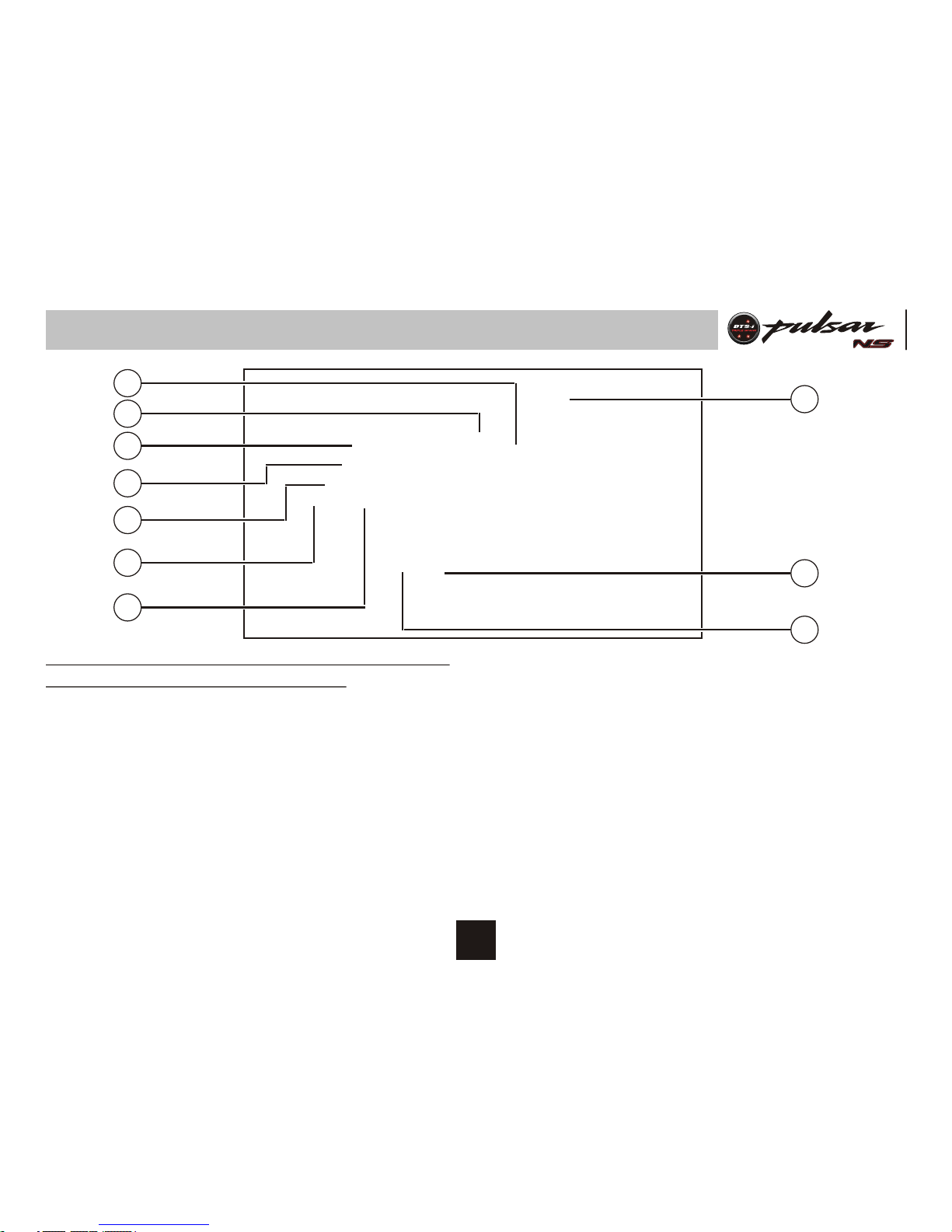
Speedometer Details
Speedometer display will work when both Ignition
switch & kill switch are in ‘ON’ position.
1. Fuel Level Indicator: It shows fuel level in fuel tank.
2. Tachometer Dial: It shows engine speed in RPM.
3. Turn Signal Indicator (LH & RH): When Turn signal
switch is turned to Left or Right, Turn pilot Indicator LH or RH will flash.
4. Neutral Indicator: When the transmission is in
Neutral, Neutral indicator will glow.
5. Hi Beam Indicator: When Headlight is ‘ON’ & Hi
beam is selected with engine running, Hi beam
indicator will glow.
6. Side Stand Indicator : When Side stand is ‘ON’, the
Side stand indicator will lit.
7. Bajaj Logo : Bajaj logo flying ‘B’ continuously glow.
8. Mode Button : Mode button used for changing the
mode while selecting & setting Trip1, Trip2, ODO,
Clock & Service reminder.
9. Set Button : Set button used for setting Clock &
Service reminder.
10. R es er ve/ En gi ne Re v Indi ca to r : I t gl ow s
continuously when petrol level in tank reaches
reserve level. It also blinks when engine RPM cross
10000 RPM mark.
8
2
7
3
4
6
5
8
9
1
10

14. Odometer : The Odometer shows the total distance
that the vehicle has covered. Odometer can not be
reset to ‘Zero’.
15. Digital Clock : It indicates time in HR : MM
(AM/PM)
16. Coolant Temperature Indicator ( ) : It blinks
0
when engine coolant Temperature is more than 115
centigrade.
17. Low Battery Indicator : It indicates battery needs
charging.
18. Trip Meter : Trip 1 & Trip 2 shows the distance
traveled since it was last reset to zero.
11. Service Reminder ( ): ‘Wrench’ symbol glows
when ODO meter reading reaches to set Kms. for
service. This Icon will flash at -
st nd
1 : 450 km 2 : 4950 km,
rd th
3 : 9950 km, 4 : 14950 km
and subsequently at each 5000 kms. Icon will
continue to glow till it is reset. This icon is to be
reset after service is carried out.
12. Low Oil Pressure Indicator ( ) : It blinks when
engine oil pressure is low.
13. Speedometer: Vehicle speed will be displayed in
digital form in Km / Hr.
Speedometer Details
9
13
15
14
16
11
17
18
12
SMSet
Mode
TRIP 1/2
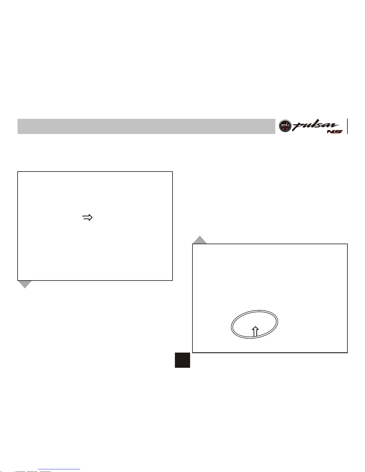
2. Service Reminder Reset ( ) :
• ‘Wrench’ symbol glows when ODO meter reading
reached to set Kms.
1. Trip Meter Reset :
• Mode & Set push button is provided for selecting &
resetting ‘ODO/TRIP1/TRIP2’. LHS part of speedo
console.
1.
Press mode push button
for less than 2 sec.
Press set push button
for more than 15 sec.
Mode changes from
‘ODO/TRIP1/TRIP2’
Selected mode
‘TRIP1/TRIP2’ will reset.
Other TRIP mode will
continue updating.
2.
1.
Press mode push button
for less than 2 sec. &
select Trip2.
Press mode & set button
for more than 5 sec.
Continuously.
Trip2 Mode selected
Service reminder icon will
be resetted.
2.
Note : Engine & motorcycle speed should be zero.
Speedometer Setting
10
SMSet
Mode
TRIP 1/2
3. Clock Reset :
• Digital clock indicates time in HR & MM separated
by colon ‘:’
• It is 12 hour clock.
• Initially ‘:’ will be blinking
• Clock setting is possible in TRIP 1 mode only.
1.
Press mode push button
for less than 2 sec.
TRIP1 Mode selected
2.
Press mode & set
push button together
for more than 2 sec.
Press mode button for
less than 1 sec.
Press set button for
less than 1 sec.
Press mode & set
button together for
more than 2 sec.
Clock set mode is
selected & no editing
is carried out for
more than 5 sec.
‘:’ stops blinking
Digits starts blinking
Hour digits will
increases by one.
Minutes digits will
increases. If mode/set
button is pressed
continuously then digits
will stop blinking.
Set value will be saved
Exit clock setting mode
Digits stop blinking
‘:’ start blinking
Auto exit without saving
set value.
If engine/vehicle rpm is
given then system will
exit from clock set mode
without saving set value.
3.
4.
5.
6.
Speedometer Setting
11
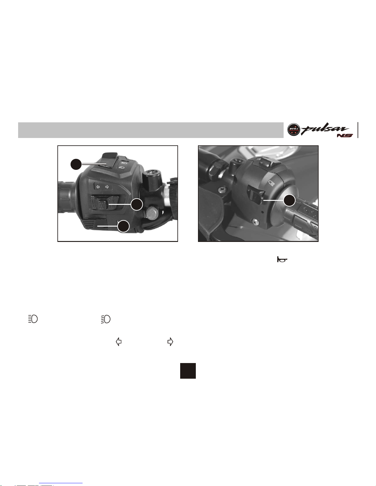
Control Switches
A
B
C
D
C. Horn Button : ( ) Press button for
sounding horn.
D. Pass Switch : Press the switch to flash
the head light. It is used to give signal to
vehicles coming from opposite side while
overtaking.
Left Handle Bar Switches
A. Dipper Switch : When headlight is ON,
High or Low beam can be selected with
the dipper switch. Hi beam indicator light
located on Speedo console will light up
when high beam is selected.
: High Beam : Low beam
B. Turn Signal Switch : When the turn signal
knob is turned to Left ( ) or Right ( )
respective indicator will start blinking, to
stop blinking push the knob in & release.
12
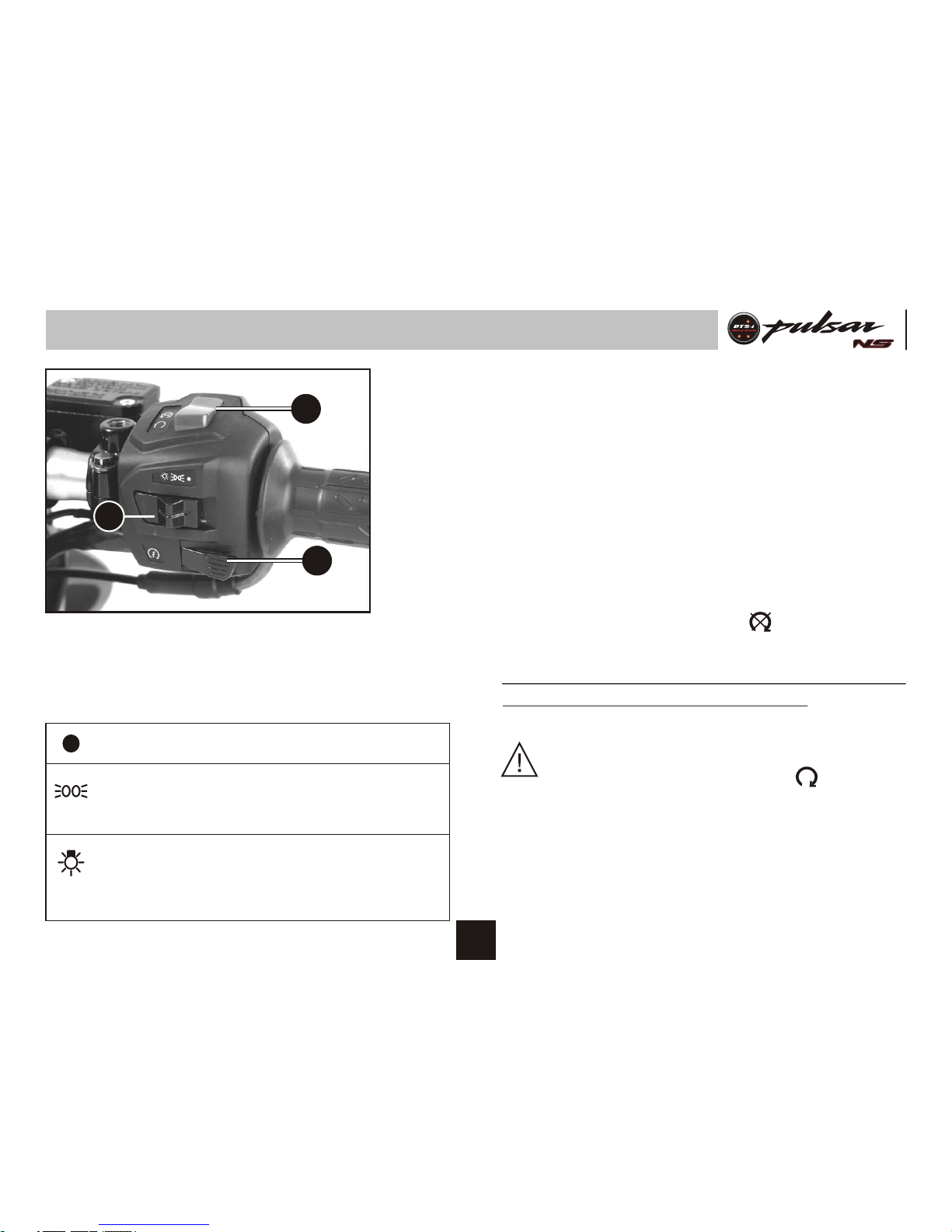
E
G
F
Control Switches
Right Handle Bar Switches
E. Head Light Switch : It has 3 positions.
: All lamps 'OFF'.
: While engine running, Tail lamp,
Meter lamp and Pilot lamp/s ‘ON’.
: While engine running, Head lamp,
Pilot lamp/s, Tail lamp and Meter
lamps ‘ON’.
F. Starter Button :
Starter button operates the electric starter
when clutch lever is depressed with
transmission in any gear.
It is recommended to start the engine with
the transmission in neutral.
G. Engine Kill Switch :
The engine kill switch is for emergency
use. During emergency move the engine
kill switch to the ‘OFF’ ( ) position.
Speedometer display will work when both Ignition
switch & kill switch are in ‘ON’ position.
CAUTION : While starting ensure that
engine kill switch is in ON ( ) position.
Keeping the kill switch in OFF position,
engine will not start.
13
Rear Seat / Tool Kit
Tool Kit
A
Tool Kit Location
• It is located below the ‘Rear seat’.
• 2 rubber straps are provided to hold the
tool kit.
Removal of Rear Seat
• Insert Key into lock (A)
• Turn the key clock wise.
• Pull upward front end of ‘Rear seat’
• Take out ‘Rear seat’
CAUTION : Always fit rubber strap for
locking tool kit.
14
Front Seat / Battery
Battery
• It is located below ‘Front seat’.
Battery details are given on ‘Battery
Maintenance’ page no. 26.
Removal of Front Seat
• First remove ‘Rear seat’.
• Remove ‘Front seat’ mounting bolts (B).
• Pull backward rear end of ‘Front seat’.
• Take out ‘Front seat’.
B
15
 Loading...