

Page 1
Foreword
Welcome to the Pulsar family!
You are now the proud owner of the next generation Pulsar 135 LS, India's No.1 sports bike. By
No.1 we are talking about unparalleled performance, superior technology and incredible market
leadership that Pulsar today enjoys. This makes the Pulsar you ride, unbeatable and unchallenged
both on and off the road.
Before you ride out, please read this Owner's Manual carefully and familiarize yourself with the
operating mechanism, controls and maintenance requirements of your Pulsar. This will ensure you a
safe and trouble free ownership experience.
To keep your bike in perfect running condition and deliver consistent performance, we have
specially programmed the periodic maintenance services which includes 3 free services and
subsequent paid services, as per the schedule contained in this booklet. We earnestly advise you
to avail all these services at any of our Bajaj Dealers or Authorised Service Centres, who are well
equipped with all necessary facilities / genuine parts / oil and trained manpower to ensure the best
care for your Pulsar. Your ‘Pulsar 135 LS’ comes with a warranty of 2 Years or 30,000 Kms
whichever occurs earlier from the date of sale. For details please refer to “Warranty : Scope &
Limits” given in this manual.
Should you require any additional information feel free to contact us on our toll free no.:
1800 233 2453 or e-mail us at: customerservice@bajajauto.co.in or visit the Bajaj Auto website
www.bajajauto.com
To be a part of the Pulsarmania, visit www.mypulsar.com and join the Pulsar fanpage on facebook:
www.facebook.com/mypulsar
Rev up, shift gears and enjoy the Pulsar experience…
SERVICE DEPARTMENT
BAJAJ AUTO LIMITED
Page 2

Description
1. Technical Specifications 1
2. Identification Data 3
3. Location of Parts 4
4. Steering cum Ignition lock 6
5. Fuel Tank Cap / Fuel Tap 7
6. Speedometer Details 8
7. Control Switches 9
8. Removal & Fitment of Side Covers 11
9. Removal & Fitment Seat 13
10. Battery / Tool kit 14
11. Daily Safety Checks 15
12. How to ride your Bike 16
13. Safe Riding Tips 20
14. Engine Oil 21
15. Wheels - Tyre 22
16. Periodic Maintenance Information 23
17. Periodic Maintenance & Lubrication Chart 27
18. Warranty Certificate 32
19. Warranty Scope & Limit 33
.
21. Service Coupons & Non Use Maintenance
20 Battery Warranty Card
Notice:
The description and illustration in this booklet
are not to be taken as binding on the
manufacturers. The essential features of the
type described and illustrated herein remaining
unaltered. Bajaj Auto Limited reserves the
right to carry out at any moment without
being obliged to bring this booklet upto-date
& to do modifications on the vehicle, parts or
accessories as may be co nvenient and
necessary.
Safety and Warning information :
Table of Contents
Caution : This indicates that a potential
ha zard th at co ul d re sult in vehicl e
damage. Follow the Advice provided with
the caution.
Warning : This indicates that a potential
hazard or injury to you or other persons &
to the vehicle can happen if advice
provided is not followed.
Page 3
Engine : 4 stroke DTS-i, Single
cylinder 4 valve (2
Intake & 2 Exhaust)
Natural air cooled.
Bore x Stroke : 54.0 mm x 58.8 mm
Eng. Displacement : 134.66 cc
Compression Ratio : 9.8:1
Idling Speed : 1400 RPM
Max. Net Power : 13.5 PS @ 9000 RPM
Max. Net Torque : 11.4 Nm @ 7500 RPM
Ignition System : DC, Digital CDI with
TRICS
Spark Plug (2 Nos) : CHAMPION, PRZ9HC
& BOSCH UR4AC
Spark Plug Gap : 0.6~0.7 mm
Lubrication : Wet sump, Forced.
Transmission : 5 speed constant
mesh.
Front Brake : Hydraulic operated 240
mm disc brake
Rear Brake : Mech. expanding shoe
130 mm dia. Drum
Fuel Tank Capacity :
Full : 8.0 liters
Reserve : 2.5 liters
Usable : 1.6 liters
Dimensions :
Length : 1995 mm
Width : 765 mm
Height : 1045 mm
Wheel base : 1325 mm
Ground clearance : 170 mm
Technical Specifications
1
Page 4

Note :
• All dimensions are under UNLADEN condition.
• Above information is subject to change without
any notice.
Tyre Size Front : 2.75 X 17”, 41 P
Rear : 100/90 X 17”, 55 P
2
Tyre Pressure Front : 1.75 kg/cm
2
Rear (Solo) : 2.00 kg/cm
2
Rear (Pillion) : 2.25 kg/cm
Electrical System : 12 Volts DC
Head Lamp : 35/35W
Pilot lamp : 5W (2 nos.)
Neutral : LED
Reserve Indicator : LED
Tail / Stop Lamp : LED
Turn Signal Indicator : LED
Side indicator Lamp : LED
Hi Beam Indi. Lamp : LED
Speedometer Lamp : LED
Fuel Gauge : LED bar display
Horn : 12V DC 2A
Battery : 12V 5Ah MF
2
Technical Specifications
}
(inside cluster)
Rear No. Plate Lamp : 5W
Vehicle Kerb Weight : 122 kg.
Gross Vehicle Weight : 252 kg.
Max. Speed : 115 km /hr. (Wi th
single rider 68kg)
Page 5

Identification Data
The Frame and Engine serial numbers are used to register the motorcycle. They are the unique
alpha-numeric codes to identify your particular vehicle from others of the same model and type.
Frame Number Location
On Side of Steering Tube
(Alpha-Numeric - 17 Digits)
Engine Number Location
On LH Side Crankcase Near Gear
Change Lever (Alpha-Numeric - 11 Digits)
3
Page 6
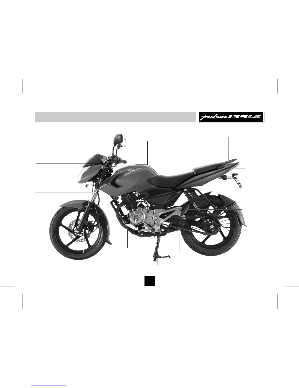
Location of Parts
4
Front Fork
Clutch Lever
Fuel Tank Cap
Nitrox Rear
Shock Absorber
Pillion
Foot Rest
Side
Stand
Gear Change
Lever
Speedometer
Disc Brake
LED Tail
Lamp
Grab Handle
Centre Stand
Page 7
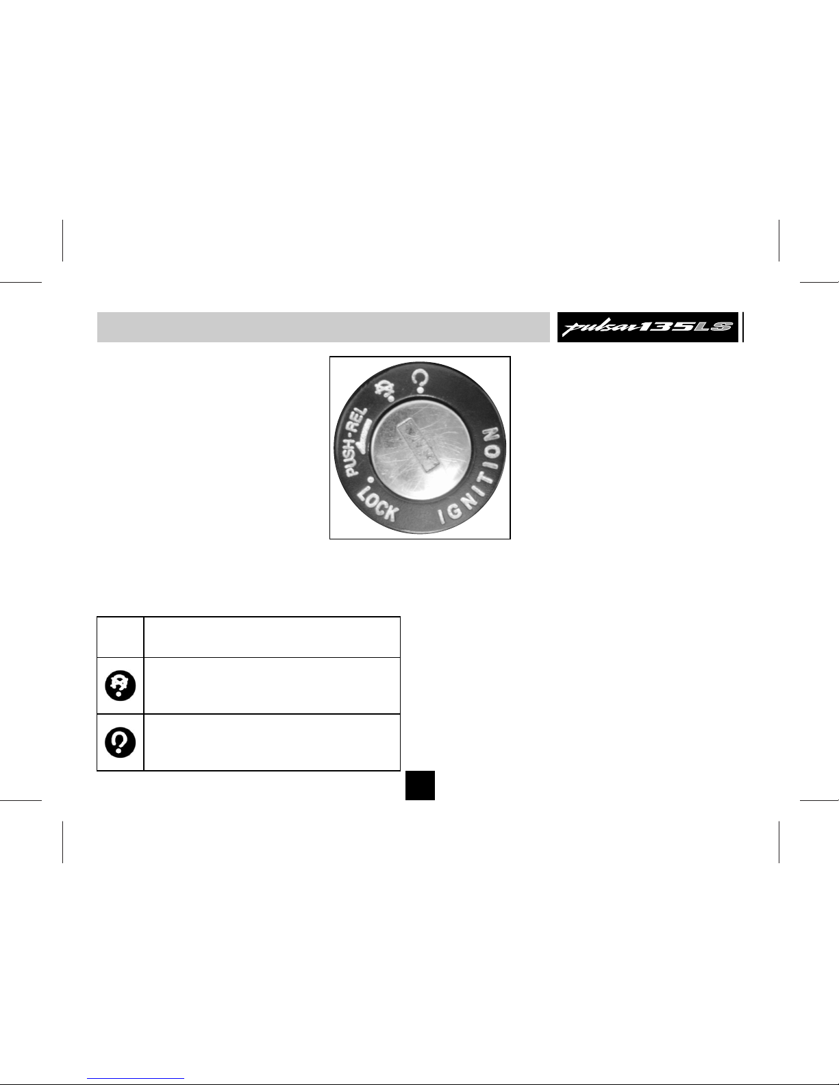
Steering cum Ignition Lock
To Lock the Steering : To lock the steering,
turn the handle bar to the left or right. Push
& release the key. Turn the key to “LOCK”
position and remove the key.
To Unlock the Steering : To unlock steering,
insert the key in steering cum ignition lock &
turn it clockwise to “OFF” or “ON” position.
Key : A common key is used for ‘Steering
cum Ignition lock’, ‘Fuel tank cap’ & ‘Side
cover lock’.
Steering cum Ignition Lock :
It has three positions.
LOCK: Steering locked. Ignition OFF.
OFF: Steering unlock. Ignition OFF.
ON: Steering unlock. Ignition ON.
6
Page 8
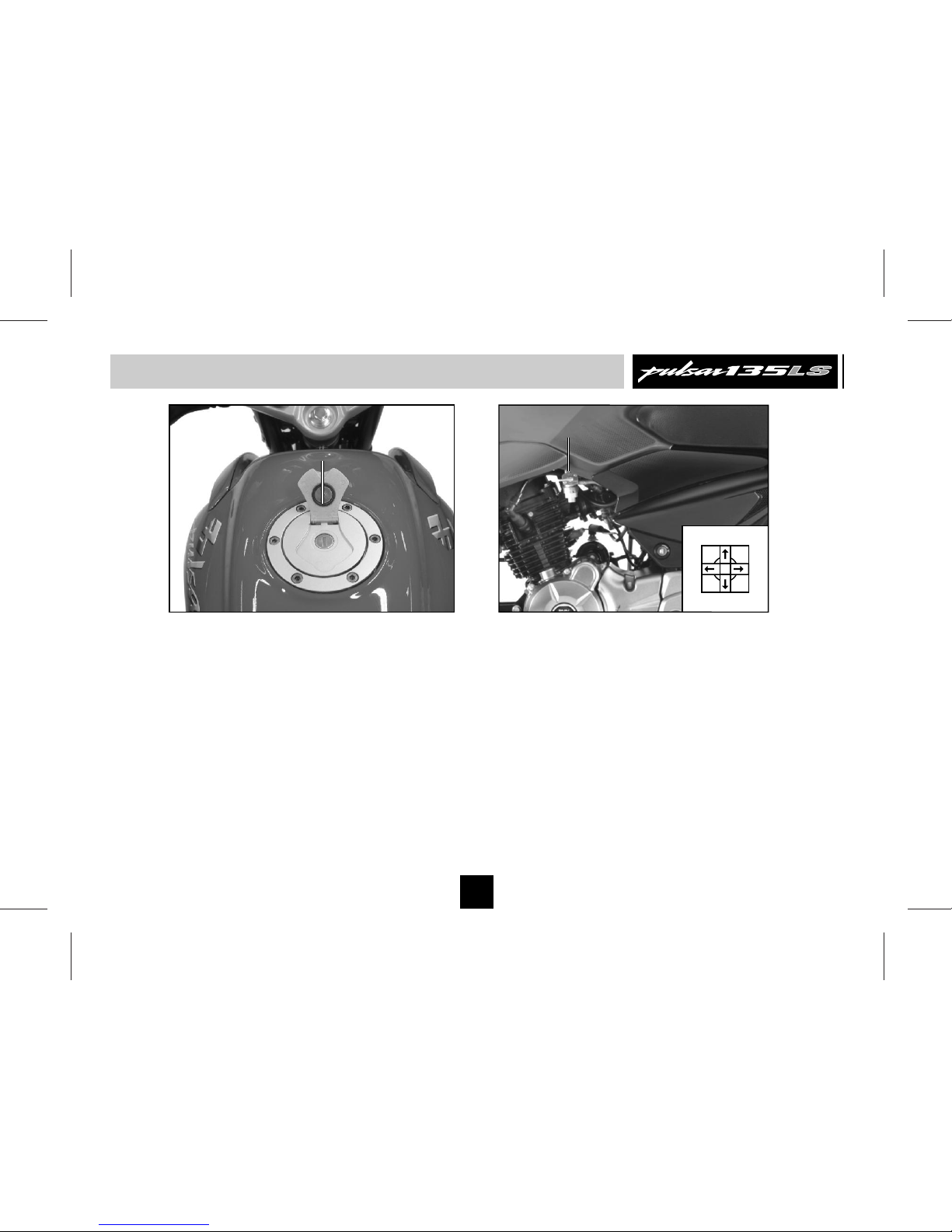
Fuel Tank Cap
• To open the fuel tank cap, open the flap.
Insert the key in the lock and turn it
clockwise and lift fuel tank cap.
• ‘Fuel Tank Cap’ gets locked when pushed
back into the place.
Fuel Tap
Fuel tap lever has following positions.
ON : When fuel level is above Reserve
position.
RES : When fuel level is below Reserve
position.
OFF : When fuel supply is to be cut off.
Fuel Tank Cap / Fuel Tap
7
Fuel Tank
Cap
OFF
ON
RES
FUEL
Fuel Tap
Page 9

7. Reserve Indicator : It shows reserve position when
petrol left in the petrol tank is 2.5 ltr. Approx.
8. Neutral Indicator : When transmission is in Neutral
and Ignition switch ‘ON’, the Neutral indicator is lit.
9. Trip Meter Reset Button : Trip meter can be reset
to zero by pressing the button.
10. Trip Meter : The Trip meter shows the distance
travelled since it was last reset to zero.
11. Battery Indicator : Shows battery charge condition.
This icon means battery is in charged condition.
Pop-up of this iocon means battery is in low charged
condition.
LOWLOW
Speedometer Details
8
1. Speedometer : The vehicle speed is displayed in
digit.
2. Fuel Level Indicator : Shows available fuel in tank.
3. Tachometer : It shows the engine speed in RPM.
4. Odometer : It shows cumulative reading of total
distance covered by vehicle in Km.
5. Turn Signal Indicator (LH & RH) : When Turn signal
switch’s knob is turned to Left or Right, Turn pilot
indicator - LH or RH will flash.
6. Hi Beam Indicator : When Headlight is ‘ON’ & Hi
beam is selected with engine running, Hi beam
indicator will be lit.
5
4
10
11
3
6
8
7
9
2
1
Page 10
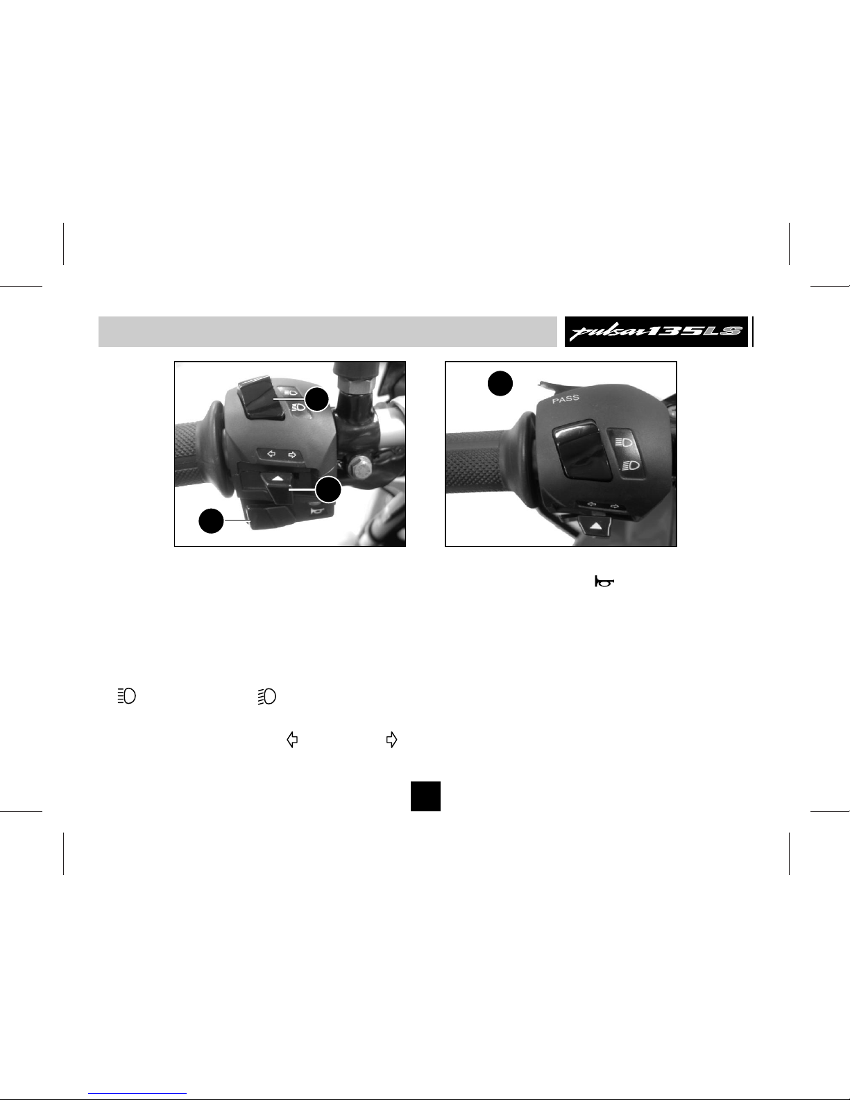
Control Switches
C. Horn Button : ( ) Press button for
sounding horn.
D. Pass Switch : Press the switch to flash
the head light. It is used to give signal to
vehicles coming from opposite side while
overtaking.
Left Handle Bar Switches
A. Dipper Switch : When headlight is ON,
High or Low beam can be selected with
the dipper switch. Hi beam indicator light
located on Speedo console will light up
when high beam is selected.
: High Beam : Low beam
B. Turn Signal Switch : When the turn signal
knob is turned to Left ( ) or Right ( )
respective indicator will start blinking, to
stop blinking push the knob in & release.
9
D
A
B
C
Page 11
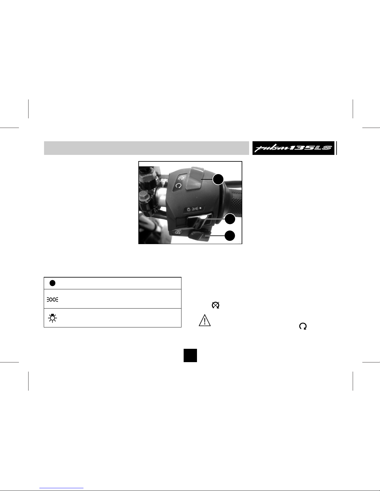
Right Handle Bar Switches
E. Head Light Switch : It has 3 positions.
: All lamps 'OFF'.
: While engine running, Tail lamp and
Pilot lamps ‘ON’.
: While engine running, Headlamp, Pilot
lamp, Tail lamp, Meter lamps ‘ON’.
transmission in any gear. It is
recommended to start engine with
transmission in neutral.
G. Engine Kill Switch :The engine kill switch
is for emergency use. During emergency
move the engine kill switch to the ‘OFF’
( ) position.
10
Control Switches
G
E
F
F. Starter Button : It operates the electric
starter when clutch lever is depressed with
CAUTION : While starting ensure that
engine kill switch is in ON ( ) position.
Keeping the kill switch in OFF position
Engine will not start.
Page 12
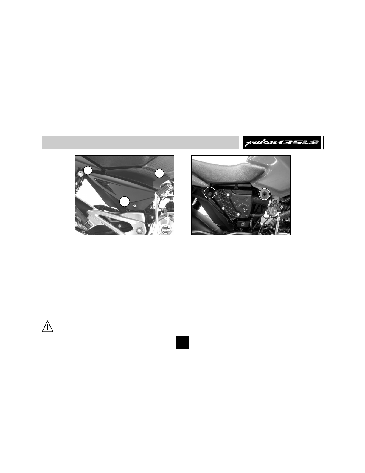
Removal & Fitment of Side Cover LH / RH
CAUTION : Remove cover as described
above, Otherwise the lugs may break.
11
Fitment of Side Cover LH
• Match slot provided on rear portion (C) of
‘Side Cover LH’ with the bracket located
on chassis & Slide (C) backward.
• Match Lug (B) provided on front portion of
‘Side Cover’ with the rubber grommet hole
provided on ‘Fuel Tank’. Press in the
cover.
• Match the ‘Side Cover Lock’ (A) properly
with the bracket provided on ‘Holder step
LH’ and Lock the ‘Side Cover’.
Removal of Side Cover LH
• Insert the key into the ‘LH cover lock’ (A)
and turn the key clockwise.
• Hold the cover with both the hands and
pull front portion (B) of the cover. Slide
rear portion (C) forward. Take out ‘LH Side
cover’.
A
B
C
Rubber
Grommet
Bracket
Page 13
Removal & Fitment of Side Cover LH / RH
12
Fitment of Side Cover RH
• Match slot provided on rear portion (C) of
‘Side Cover LH’ with the bracket located on
chassis and slide (C) backward.
• Match Lug provided on front side (B) of
‘Side Cover’ with rubber grommet hole
provided on ‘Fuel Tank’ and press in ‘Side
Cover RH’.
• Match ‘Side Cover’ properly with bracket
provided on ‘Air filter assly’ and fix it with
Screw (A).
Removal of Side Cover RH
• Remove the screw (A) securing the ‘Side
Cover RH’.
• Hold the cover with both the hands and
pull front portion (B) first. Slide (C) forward.
Take out ‘Side cover RH’.
CAUTION : Fit cover as described above
to ensure proper fitment.
A
B
C
Rubber
Grommet
Bracket
Page 14

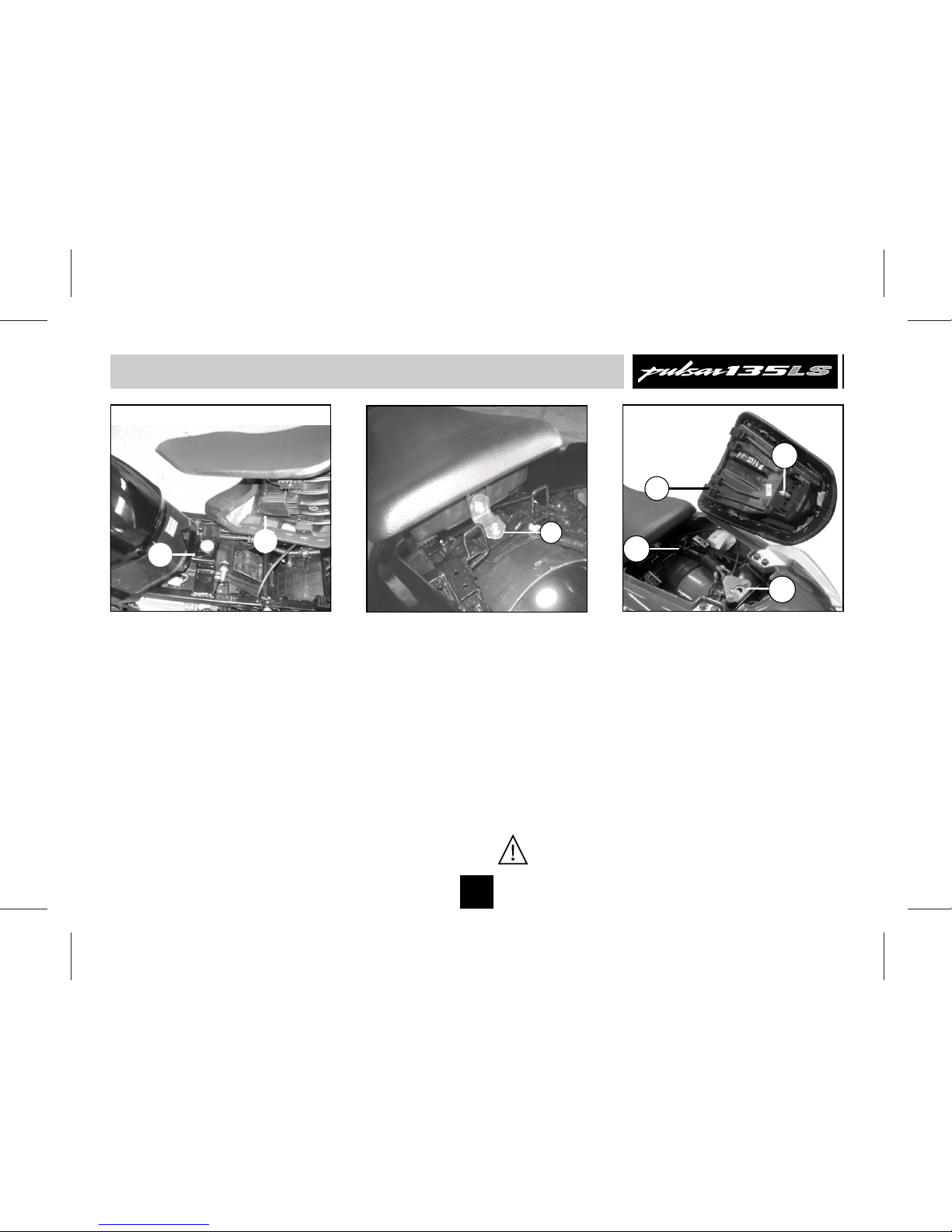
Removal & Fitment of Seat
13
Removal of Seat - Rear
• Remove ‘Side Cover’ LH.
• To remove Seat Rear, pull the ‘Seat
Release Cable’ (A) shown in fig. 1 to
release seat lock. Keeping cable pulled,
tap the center of seat, lift the seat from
rear end and slide it towards tail lamp to
remove seat.
Fig. 1 Seat release cable
Fig. 2 Seat mounting bolt
Removal of Seat - Front
• Remove ‘Side Cover’ LH.
• Remove ‘Seat Rear’.
• To remove Seat Front, remove bolt (B)
shown in fig. 2
• Lift the seat from rear end and slide it
towards tail lamp to remove seat.
CAUTION : Always remove Rear seat
first.
A
B
Page 15
Removal & Fitment of Seat
13
Fitment of Seat - Front
• For fitment of Seat Front, match & insert
the bracket (‘1’ of Fig. ‘A’) of seat with slot
(‘2’ of Fig. ‘A’) provided below fuel tank
rear mounting on chassis. Push seat
towards fuel tank.
• Then press the seat at rear from top to
align lock bolt (‘3’ of Fig. ‘B’).
• Tighten the lock bolt.
Fitment of Seat - Rear
• For fitment of Seat Rear, match & insert
bracket (‘4’ of Fig. ‘C’) of seat with bracket
(‘5’ of Fig. ‘C’) provided on chassis.
• Push seat towards fuel tank & align lock
rod (‘6’ of Fig. ‘C’) & seat lock (‘7’ of Fig.
‘C’).
• Then press the seat in middle from top to
lock the seat.
Fig. A Fig. B Fig. C
1
2
3
4
5
6
7
CAUTION : Always fit Front seat first.
Page 16
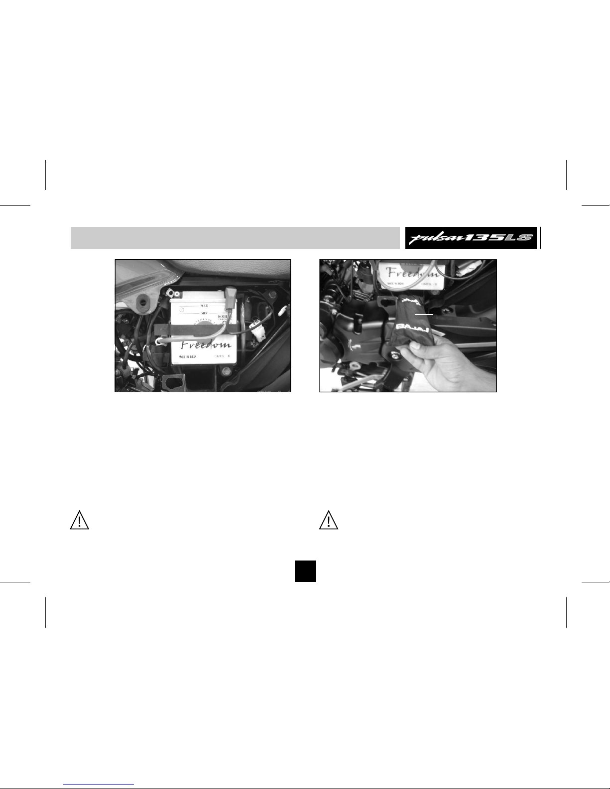
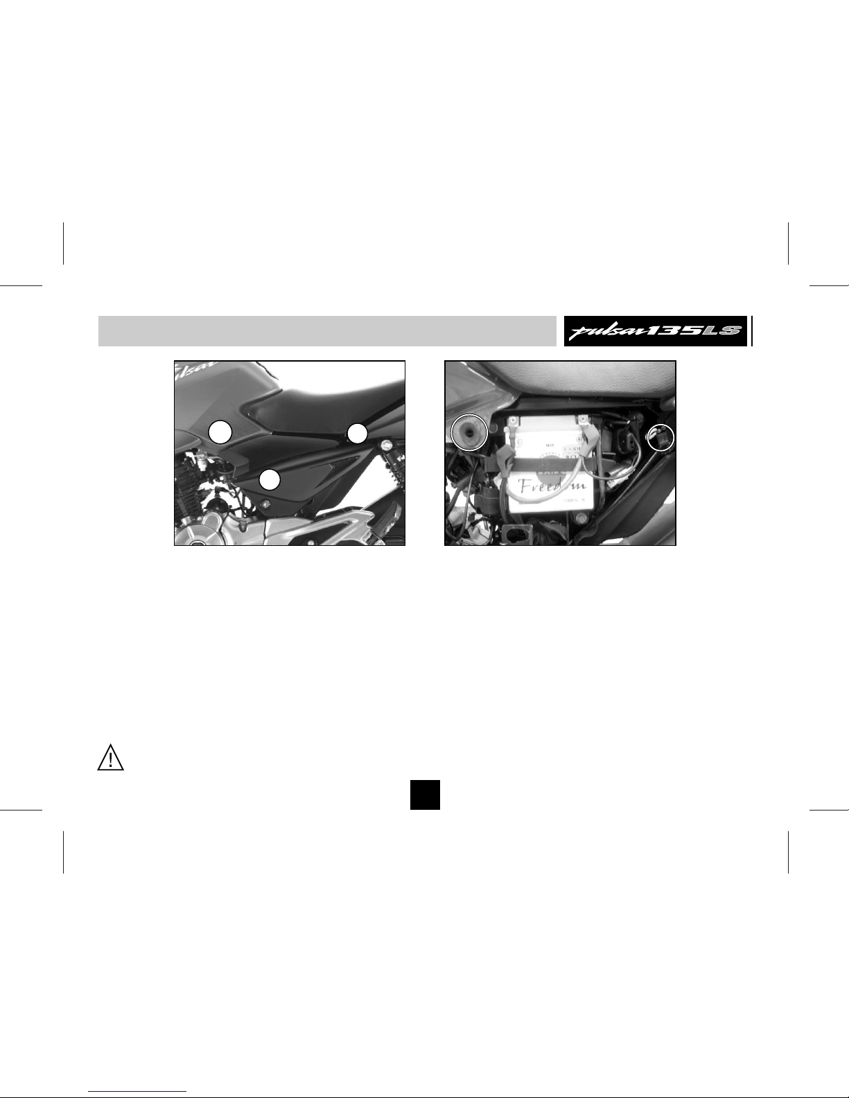
Battery / Tool Kit
14
Tool Kit Location
• It is located below the battery.
Battery
• It is located inside the ‘Side Cover’ LH.
• Always maintain electrolyte level in each
cell between max and min level lines.
• Always keep a watch on battery charge
level indicating icon, if it flashes (indicates
battery is in low charged condition), show
the vehicle to authorised BAL dealer.
CAUTION : Do not drive/run vehicle in
battery disconnected condition. It may
lead to damage of electrical / electronic
components.
CAUTION : Insert tool kit properly in
compart ment p ro vided on air filte r
assembly for proper fitment of ‘LH’ side
cover.
TOOL KIT
BATTERY
Page 17
Daily Safety Checks
• Brake Pedal Play - 20 to 30 mm.
• Wear lining Indicator within usable range.
No brake dragging, applicable to drum
brake vehicles.
• Bra ke Flu id lev el abo ve MIN m ark
provided on reservoir, applicable to disc
brake vehicle.
• Drive Chain slack of 25 to 30 mm
adequately lubricated.
• Function of all lights & horn
• Clutch lever play - 2 to 3 mm
• Smoot h st eerin g mo vemen t wi thout
restriction.
• Both stand return to their fully up position.
• Correct inflation pressure in both tyres
Adequate tyre tread depth - no cracks /
cuts.
• Correct rear viewing span adjustment of
mirror.
Before riding motorcycle be sure to check
following items. Please give proper importance
to these checks and perform all of them
before riding motorcycle.
If any irregularities are found during these
checks, refer to the Maintenance chapter &
see your dealer for the action required to
return the motorcycle to a safe operating
condition.
Warning : Failure to perform these
checks every day before you ride may
result in serious damage or severe
accident.
• Enough fuel level for planned distance of
journey. No fuel leakage in fuel lines.
• Engine oil level (between upper and lower
level mark)
• Throttle cable play of 2 ~ 3 mm. Smooth
operation and positive return to closed
position,
15
Page 18

How to Ride Your Bike
Starting The Engine :
• Turn the fuel tap knob to ‘ON’ or ‘RES’
position.
• Switch ‘ON’ ignition & ‘Kill Switch’
• Confirm that transmission is in neutral.
• Fold R.H side rider footrest.
• Keep throttle completely closed, press
starter button “ ” / apply kick to start the
engine.
• Release starter button / kick lever as soon
as engine starts.
• Open R.H side rider footrest back to its
position.
Warning : During kick starting if rider
footrest is not folded, kick lever hits the
footrest a nd severe jerk wou ld get
experienced at foot. Also rider step holder
would get damaged due to impact.
Moving Off :
• Check that Center/Side stand is up.
• Depress the clutch lever.
st
• Shift into 1 gear.
• Open the throttle and release the clutch
lever slowly and simultaneously.
• As the clutch starts to engage, open the
throttle a little more, giving the engine just
enough rpm to keep it from stalling.
Caution : Do not operate the starter
continuously for more than 5 seconds
otherwise battery would get discharged.
Wait 15 sec. between each operation of
the starter which will facilitate battery to
recover.
Note : Do not let the engine idle longer than 3
minuets otherwise it will overheat.
Note : The motorcycle is equipped with a
starter lockout switch. This switch ensures that
engine does not start if the transmission is in
gear.
However, the engine can be started in any
gear if the clutch lever is pressed.
Before starting the engine, in ignition key
off condition, press the clutch lever & operate
kick starter lever all the way down for 5-6 times.
Then release the clutch lever.
This practice ensures lubrication of clutch
components for their longer life.
Note :
16
Page 19

Braking :
• Close the throttle completely, leaving the
clutch engaged (except where shifting gears)
so that the engine braking will help slow
down the motorcycle.
• Shift down one gear at a time so that you
are in Neutral when you come to a complete
stop.
• When stopping, always apply both brakes at
the same time. De-clutch as necessary to
avoid engine stalling.
• Never lock the brakes, or it will cause the
tyres to skid. When cornering, use brakes
judiciously & do not de-clutch. Reduce your
speed before you get into the corner. For
emergency braking, disregard downshifting,
and concentrate on applying brakes as hard
as possible without skidding.
th th
From 5 to 4 Gear
th rd
From 4 to 3 Gear
rd nd
From 3 to 2 Gear
nd st
From 2 to 1 Gear
45 km/h
35 km/h
25 km/h
15 km/h
Recommended Speed for Shifting Down
Warning : When shifting down to lower
gear, do not shift at such high speed that
engine rpm jumps excessively. This may
cause engine damage, & rear wheel may
skid. Downshifting should be done at
recommended speeds as shown in table.
17
How to Ride Your Bike
Shifting Gears :
• Close throttle & depress the clutch.
• Shift into next higher or lower gear.
• Open the throttle and release the clutch
lever slowly and simultaneously.
Gear Shifting
Pattern
N
1
2
3
4
5
Gear Shifting Lever
Page 20

Stopping the Vehicle :
• Close the throttle completely.
• Shift the transmission into neutral.
• Bring the vehicle to complete stop.
• Turn the ignition switch off.
Parking the Vehicle :
• Support the motorcycle on a firm level
surface with the center or side stand.
• Lock the steering.
Running IN
Proper running-in is important for the better
life & trouble free performance of the vehicle.
• During first 2000 kms running-in period do
not exceed following speed limits.
• Always keep the speed below the limits
mentioned in the table.
• Do not race the engine excessively.
• Do not start moving or race the engine
immediately after starting. Run the engine
for a minute at idle speed to give the oil a
chance to workup into the engine.
How to Ride Your Bike
CAUTION : Do not park on a soft or
steeply inclined surface or the motorcycle
may fall over.
18
Kms 1st 2nd 3rd 4th 5th
0 - 1000 14 22 31 38 45
1000 - 2000 19 31 43 52 62
Page 21

How to Ride Your Bike
Fuel Saving Tips :
A well maintained vehicle and good driving
can contribute a lot to the saving of petrol.
Following are a few simple fuel saving tips.
Good Riding Habits :
• Ride smoothly and steadily at an optimum
driving speed of 40 to 50 Km/h
• Avoid harsh braking.
• Change the gear judiciously according to
the speed and load requirement.
• Don’t overload the vehicle above the
specified payload.
• Use the accelerator judiciously.
• Cut off the engine if you want to stop for
more than two minutes.
How to check mileage (Fuel efficiency)
Best way to calculate mileage is by following
the full tank to full tank method.
• Fill way tank full up to small mouth (brim).
• Run the bike for say 100 km.
• Fill the tank full again in same fuel filling
station, probably with same fuel dispenser.
• Divide kilometer run / fuel quantity filled.
19
Fuel Check fuel lines & connections
for leakage.
Spark plugs Inspect and clean spark plugs.
Adjust electrode gap.
Air filter C l ea n a i r f i lt e r e l e m en t
periodically.
Engine oil Check level. Use recommended
grade and quantity.
Brakes Ensure that the brakes are not
dragging / binding.
Clutch Ensure correct clutch lever play.
Tyre Always maintain recommended
Pressure. tyre pressure.
Carburettor Clean & adjust the carburettor.
Adjust idling speed.
Ensure following maintenance points to get
optimum fuel efficiency from your bike.
Optimum Shifting Speeds for best mileage
1st gear : 0 km/h
2nd gear : 15 ~ 18 km/h
3rd gear : 24 ~ 27 km/h
4th gear : 33 ~ 36 km/h
5th gear : 41 ~ 44 km/h
Page 22

Safe Riding Tips
• Drive cautiously. Start early & reach your destination
safely.
• Always carry vehicle registration & insurance papers,
and a valid driving licence with you.
• Avoid driving on loose sand or stones where vehicle
is likely to skid.
• Properly wrap-up loose clothes while driving or riding
to avoid entangling in wheel or other objects on road.
• Always concentrate on riding for safety.
Monsoon Care :
• It is suggested to customer to take appropriate care
in area of heavy monsoon or high rainfall area. The
appropriate surface preventive coat to avoid rusting /
poor surface finish on account of adverse atmospheric
conditions.
• Vehicle cleaning to be done with soft & clean wet
cloth to avoid scratches on painted parts.
• Clean & lubricate all the important parts as detailed in
a periodic maintenance chart.
• Do not apply direct water jet on painted, electrical /
electronic parts.
• Do not obstruct engine cooling by adding mud
protection sheet from front.
Safe Riding Tips
• Always wear Helmet while driving or riding. Your
he lmet should conform to appropriate In di an
standards.
• Read thoroughly the instructions
given in this manual and follow
them carefully.
• Avoid unnecessary accessories
for the safety of both rider and
other motorists.
• Get familiar and follow traffic rules & regulations in
your states as well as general traffic signs.
• Familiarise yourself well with starting, acceleration and
braking of the vehicle.
• When applying the brakes, use both front & rear
brakes simultaneously. Applying only one brake may
cause the vehicle to loose control.
• Riding at proper speed and avoiding unnecessary
acceleration and braking are important not only for
safety and low fuel consumption, but also for longer
life of the vehicle.
• During monsoon drive the vehicle more cautiously.
Remember vehicles skid more easily during light
showers.
20
Page 23

Engine Oil
A : Oil Filler
Cap
B : Oil Level
Gauge
Engine Oil Level Checking :
• Check engine oil level every day. Park
vehicle on level surface on center stand.
• Check oil level through oil level gauge ‘B’.
• Always maintain engine oil level between
upper (C) and lower (D) mark provided on
Cover RH. Top up with specified grade of
oil if the oil level is below lower level mark.
Engine Oil Capacity :
• Refill at servicing : 1000 ml.
• During engine overhaul : 1100 ml.
Recommended Engine Oil:
Always insist on Bajaj Genuine
Engine Oil for optimum engine
perf orma nce a nd warr anty
ben efit s. It is a spec iall y
formulated oil for vehicles with
DTS-i engines.
Model Recommended Grade
Engine oil
Pulsar Bajaj DTS-i SAE 20W50 API
135 LS 10000 ‘SL’ or JASO ‘MA’
st
• Engine oil replacement frequency : 1 service &
then every 10,000 Km.
• Engine oil level top-up frequency : Every 5000 km.
CAUTION :
• It is most important to adhere to
recommended grade & frequency of oil
change for the purpose of long life of
critical engine components. For details
refer periodic maintenance chart.
• Do not reuse drained oil.
21
A
B
C
D
Page 24

Wheels - Tyre
Use the recommended levers while removing
the Tyre / Tube for puncture work. This will
avoid any damages to the edges / scratches
on paint of the wheel.
Tyre Pressure :
Keep appropriate tyre pressure as mentioned
below to increase life of the tyre & for better
fuel consumption.
Note : Incase the motorcycle is fitted with
imported tyres. compliance to respective indian
standard & central motor vehicle rules has been
ensured.
2
Front 1.75 kg/cm
2
Rear (Solo) 2.00 kg/cm
2
Rear(with Pillion) 2.25 kg/cm
Front Wheel
22
Pulsar 135 LS
Page 25

Periodic Maintenance Information
23
Front Brake Fluid Level :
• Front brake fluid reservior is located on RH
side of Handle bar.
• To check oil level, keep the vehicle on
center stand with handle bar in straight
ahead condition.
• Always ensure that brake fluid level is
above ‘MIN’ mark given on inspection
Window.
Battery
• Battery type : 12V 5Ah
• Battery Warranty : 18 months from date of
purchase.
• Add only distilled water to the battery if
battery electrolyte level is below min. level
mark.
Max
Min
CAUTION : Tap water is not a substitute
for distilled water and will shorten the life
of the battery.
Min. Level
Page 26

Periodic Maintenance Information
24
• When battery is found discharged, it is
advised to get it charged immediately.
• Environ ment c are mu st be taken to
dispose off the used battery. It is always
recommended to hand over the same to
the Authorised battery / Bajaj dealer for
proper disposal of the same.
How to keep battery healthy ?
• Switch ‘Off’ ignition when engine is not
running.
• Get battery checked/ charged during
periodic services.
• Do not press starter button for more than
5 sec. After 3 successive cranking, wait for
15-20 sec. for battery to recover.
• Do not add extra electrical accessories
such as - Remote, Bigger horn, Musical
brake light etc. This will reduce life of
battery
• If vehicle is to be stored for more than 2
weeks disconnect battery to avoids self
discharge.
CAUTION :
• While disconnecting always disconnect
negative (-ve) cable first.
• While refitting always connect positive
(+ve) cable first.
Page 27

Periodic Maintenance Information
Spark Plug
• Rem ove spa rk plu gs b y using p lug
spanner.
• Clean the spark plugs.
• Adjust the gaps if incorrect by bending
outer electrode carefully.
Spark Plug Gap : 0.6 to 0.7 mm.
Spark Plug (2 Nos.) : BOSCH OR
: CHAMPION
0.6 to
0.7 mm
Drive Chain Slackness
• Chain top edge to be kept between the
two mark s d u r i ng chain s l a c kness
adjustment.
• Chain slackness will have to be adjusted
whenever required.
• Std. Chain slackness 25 ~ 35 mm.
• Marking on chain adjusters should be
identically positioned on both sides.
25
Std. Chain
slackness : 25~35 mm
Page 28

Periodic Maintenance Information
Drive chain must be cleaned & lubricated as
per periodic maintenance schedule.
a. Drive chain (Non O-ring type)
• Non O-ring type chain should be removed &
cleaned by Nylon brush & Kerosene or in
Chain Cleaning Machine.
• It should be lubricated by SAE 90 grade oil.
b. Drive chain (O-ring type)
• ‘O’ rings must always be kept wet for best
performance hence lubricate every 500 Kms
• O-ring chain lubrication can easily be done
by owners using Bajaj ‘Chain Lube Spray
Can’ available with Bajaj dealers.
Method of O-ring Chain Lubrication :
• Place the bike on centre stand.
• Clean the chain by using lint free cloth (If
excessive mud / slush found approach Bajaj
Service Center for proper cleaning)
• Shake the can vi go ro us ly by holding
vertically upright till the noise of steel ball
inside heard uniformly.
• Hold spray can at the back of rear sprocket
with extension tube nose at 5~10 cm.
• Rotate the wheel in reverse direction &
spray the lube on middle portion of the
chain up to full length of the chain.
Drive
Chain
Cleaning
Drive
Chain
Lubrication
26
Page 29

Periodic Maintenance & Lubrication Chart
27
1st - 500~750 Kms / 30~45
1. Servicing 3 3 3 3 3 3 3
days,2nd onward@5000Kms
2. Idle speed / CO% C, A C, A C, A C, A C, A C, A C, A C, A
3. Valve tappet clearance C, A C, A C, A C, A C, A C, A C, A C, A
4. Engine oil (Bajaj DTSI 10000 oil)* C, A R Top-up R Top-up R Top-up R Top-up@every 5000 Kms.
Replace in 1st service & at
every 10000 Kms
5. Oil strainer (Bajaj DTSi 10000 oil)* CL CL CL CL CL
6. Engine oil filter (Bajaj DTSi 10000 oil)* R R R R R Replace at every oil change
7. Body centrifugal filter -- Pulsar / Platina CL CL CL
8. Spark plug gap CL,A CL,A CL,A CL,A CL,A CL,A CL,A
9. Spark plug R R Replace at every 20000kms
10. Air cleaner element*** CL, R CL CL CL R CL CL R Replace at every 15000kms
11. Air filter cover ‘O’ ring R R R Replace at every 15000kms
12. In line paper filter along with hose & clamps** R R R Replace at every 15000kms
13. Fuel cock sediment bowl cleaning CL CL CL CL CL CL CL
14. Fuel cock-Paper filter element & seal** R R R Replace at every 15000kms
15. Carburettor CL,A CL,A CL,A
RECOMMENDED FREQUENCY
Servicing
Sr.
No.
Operation
1st
500
~
750
2nd
4500
~
5000
3rd
9500
~
10000
4th
14500
~
15000
5th
19500
~
20000
6th
24500
~
25000
7th
29500
~
30000
Kms
Subsequent
Page 30

Periodic Maintenance & Lubrication Chart
28
16. Carburettor float chamber cleaning CL CL CL CL
17. Carburettor rubber duct C,R C,R Check & replace if required
18. Fuel pipes C,R C C C R C C R Replace at every 15000kms
19. Coolant level check in expansion tank** C,A C,A C,A C,A C,A C,A C,A At every service
20. Coolant in expansion tank** R Replacement at every 30000 Kms or 2 year (whichever occurs earlier)
21. Coolant hose damage/clamps/leakage** C,R C,R C,R C,R C,R C,R C,R Check & replace if required
22. Coolant hose damage/clamps/leakage** R Replacement at every 35000 Kms or 3 years (whichever occurs earlier)
23. Radiator fins** C,A C,A C,A C,A C,A C,A C,A
24. Battery electrolyte level & specific gravity** C C C C C C C C
25. Battery connections C,T C,T C,T C,T C,T C,T C,T
26. Clutch plate C,R C,R Check & replace if required
27. Clutch play C,A C,A C,A C,A C,A C,A C,A C,A
28. Throttle play C,A C,A C,A C,A C,A C,A C,A C,A
29. Brake play C,A C,A C,A C,A C,A C,A C,A C,A
30. Brake lining or pad wear C,R C,R C,R C,R R C,R C,R C,R Replace at every15000 Kms
31. Brake fluid level / top up** C,A C,A C,A C,A C,A C,A C,A Check & Top up if required
in every service
500
~
750
4500
~
5000
9500
~
10000
14500
~
15000
19500
~
20000
24500
~
25000
29500
~
30000
RECOMMENDED FREQUENCY
Servicing
Sr.
No.
Operation
1st
2nd
3rd
4th
5th 6th
7th
Kms
Subsequent
Page 31

Periodic Maintenance & Lubrication Chart
29
32. Brake fluid R R
33. Front brake hose R R
34. Master cylinder piston kit R R
35. Caliper piston seal and Dust seal R R
36. Brake cam & pedal pivot pin** L L L L L L L
37. Rear sprocket fasteners C,T C,T C,T C,T C,T C,T C,T C,T
38. Rear wheel rubber shock damper C,R C,R C,R C,R Check & replace if required
39. Silencer drain hole cleaning CL CL CL CL CL CL CL
40. Silencer tail pipe cleaning-Pulsar 150/180 CL CL CL CL CL CL CL
41. Engine compression pressure C C C
42. Cylinder head de-carbonising CL CL If required
43. Engine air breather tube R R Replace at 20000 Kms
44. Drive chain slackness C,A C,A C,A C,A C,A C,A C,A C,A
45. Drive chain lubrication on vehicle C,L C,L
46. Drive chain link lock R R R R R R R Whenever drive chain opened.
47. Drive chain wear -- Remove & Lubricate C,L C,L C,L C,L C,L C,L C,L
48. Drive chain ("O" ring design)** L Lubricate at every 500 km.(By customer)
49. Wheel bearing C,R C,R C,R C,R C,R C,R Check & replace if required
500
~
750
4500
~
5000
9500
~
10000
14500
~
15000
19500
~
20000
24500
~
25000
29500
~
30000
RECOMMENDED FREQUENCY
Servicing
Sr.
No.
Operation
1st
2nd
3rd
4th
5th 6th
7th
Kms
Subsequent
Page 32

Periodic Maintenance & Lubrication Chart
30
500
~
750
4500
~
5000
9500
~
10000
14500
~
15000
19500
~
20000
24500
~
25000
29500
~
30000
50. Spoke tightening-Front & Rear** C,T C,T C,T C,T C,T C,T C,T C,T
51. Tyre tread wear C,R C,R C,R C,R C,R C,R Check & replace if required
52. Front fork oil R R R R Replace at every 10000kms
53. Front fork oil seal R R R R Replace at every 10000kms
54. Auto choke** C C C C C C C
55. Gap betn Reed switch & TPS magnet** C,A C,A C,A C,A C,A C,A C,A C,A
56. Rr. Shock Absorber- Check gas pressure** C,A C,A Not required for new design
(Filling from bottom)
57. Starter Clutch** (Dry Application) L L L L L L L
58. Wiring harness C C C C
59. Ignition switch contacts cleaning C,CL C,CL C,CL C,CL C,CL C,CL C,CL C,CL
60. Clutch switch & brake switch
(Horizontal base) contacts cleaning** C,CL,L C,CL,L C,CL,L C,CL,L
61. Clutch switch (Vertical base)** C,R C,R C,R C,R Check & replace if required
62. Rear brake switch C,A C,A C,A C,A C,A C,A C,A C,A
63. Starter motor connections** C,T C,T C,T C,T C,T C,T C,T
64. Starter relay connections** C,T C,T C,T C,T C,T C,T C,T
RECOMMENDED FREQUENCY
Servicing
Sr.
No.
Operation
1st
2nd
3rd
4th
5th 6th
7th
Kms
Subsequent
Page 33

Periodic Maintenance & Lubrication Chart
31
Note : Periodic parts / lubricants to be replaced as per Periodic Maintenance and Lubrication Chart are mandatory and
the same are chargeable to customer.
* It is strongly recommended to use only “Bajaj DTS-i 10000” Genuine engine oil. In case any other engine oil of
same specifications is used, the frequency of Sr. No. 4, 5 & 6 will be every 5000 Kms.
** As applicable to model
*** More frequent cleaning may be required when driving in dusty condition.
C : Check, A : Adjust, CL : Clean, R : Replace, T : Tighten, L : Lubricate
500
~
750
4500
~
5000
9500
~
10000
14500
~
15000
19500
~
20000
24500
~
25000
29500
~
30000
65. HT coil connections C,T C,T C,T C,T C,T C,T C,T
66. Oil pressure indicator check on console** C C C C C C C C
67. General lubrication L L L L L L L L
68. Main stand & side stand pin** C,L C,L C,L C,L
69. Swing arm pivot pin (for non silent bush)** L L L L L L L
70. Engine foundation silent bushes** R R R Replace at every 15000Kms
71. Steering play C,A C,A C,A C,A C,A C,A C,A C,A
72. Steering stem bearing*** C,CL,L,R C,CL,L,R C,CL,L,R C,CL,L,R Check & replace if required
73. Cap steering bearing (Plastic)** C,R C,R C,R C,R
74. Step -Pillion LH & RH (Ball & Plate)** C,CL C,CL C,CL C,CL C,CL C,CL C,CL
75. All fasteners tightness C,T C,T C,T C,T C,T C,T C,T C,T
RECOMMENDED FREQUENCY
Servicing
Sr.
No.
Operation
1st
2nd
3rd
4th
5th 6th
7th
Kms
Subsequent
Page 34

Warranty Certificate
FRAME NO. :
ENGINE NO. :
Registration No. :
Sold on (DD / MM / YY)
To the Customer’s Mr/Mrs/Miss :
Address :
Contact No.:
By the Dealer M/s :
Address :
Contact No.:
SAP Code :
The vehicle is warranted for 2 Years or 30,000 Kms. whichever occur
earlier from the date of sale as per terms & conditions given in
Warranty : Scopes and Limits.
SERVICE DEPARTMENT
BAJAJ AUTO LIMITED
32
Page 35

Warranty : Scope & Limit
Bajaj Auto Limited gives the following warranty in respect
of the motorcycle manufactured by
them.
Every possible care and precaution has been taken to
ensure quality in respect of the material & workmanship in
the vehicles manufactured by us. Bajaj Auto Limited will
repair or replace at their Authorised Workshops, free of
charge, part or parts there of as may be found, on
examination, to have manufacturing defect within a period
of 2 Years or 30,000 Kms., whichever occurs earlier from
the date of sale subject to fulfillment of condition stipulated
in part A, B & C given here under
Warranty is applicable for only first owner of vehicle.
Part A:
Warranty claims in respect of such items like shock
absorbers, speedometers etc. though claimed through us,
are subject to acceptance of the respective manufacturers.
In all such cases the decision of the respective
manufacturer will be final and binding.
Proprietory parts like tyres, tubes, battery and spark plugs
are warranted by their respective manufacturers (Only one
year warranty from the date of purchase/as applicable)
and should be claimed on them directly by the customer.
Bajaj Auto Limited shall not be Liable to replace them
“Pulsar 135 LS”
though their dealer will give full assistance in preferring
such claims.
Bajaj Auto Limited undertake no liability in the matter of
consequential loss or damage caused due to the failure of
the parts. Delay, if any, at the repairing workshop in
carrying out repair to vehicle shall not be a ground for
extending the warranty period, nor shall it give any right to
the customer for claiming any compensation for damages.
Bajaj Auto Limited reserves the right either to repair or
replace the defective parts.
Where a defective part can be replaced by part/s of
alternative brand/s, which are normally used by Bajaj
Auto Limited in the course of manufacture, Bajaj Auto
Limited reserves the right to carry out the replacement
by a part or parts of any such alternative brand/s.
This warranty and any claim arising there from is subject
to Pune jurisdiction only.
Part B:
No claim for exchange or repair can be considered
unless the customer :
a. Ensures that immediately upon detection of the
defect, he approaches any nearest Authorised Bajaj
Vehicle Dealers & Recommended Authorised Service
Centers with the concerned vehicle and enables him
33
Page 36

to remove and despatch the part / parts attributing to
the manufacturing defect to the Company.
b. Produces the Owner's Manual, in original, to enable
that dealer to verify the details.
It must be expressly understood that claims forwarded
directly to us by the owner / customers will not be
entertained at all and such defective part/parts thus
forwarded by them will lie at our factory at their own
risk, and this warranty shall not be enforceable.
To avail benefits of warranty, following are
mandatory
1. Availing of Initial 3 Free Services without lapse.
2. Availing 4 paid services at every 5000 kms. or 120
days whichever occurs first without any lapse.
3. Availing of all above services at the Authorised
Vehicle Dealers & Recommended Authorised Service
Centers.
4. Maintaining all service records duly signed and
stamped by dealers.
Usage of only recommended engine oil
at specified frequency for drain
interval of 10,000 kms. & engine oil level top-up at
5000 kms.
6. Replacing mandatory periodic parts such as air filter,
oil filter etc. as per periodic maintenance schedule.
5.
“Bajaj DTS-i 10000”
Part C :
Further this warranty is NOT applicable to :
1. Normal maintenance operations like brake & clutch
adjustments, cleaning of fuel system, engine tune-up
or such other adjustments.
2. Parts subjected to normal wear & tear like Clutch
Plates, Brake Shoes, Chain, Sprockets, Fork Oil
Seal, Spark Plug, Control Cables, Brake Pads.
3. Replacement of electrical items like self-start’s wear
and tear items (if fitted), bulbs & rubber components
like grommets, ‘O’ rings, bellows as well as filters,
packings, gaskets, fasteners etc.
4. Painted parts. Only blistering or peeling off of paint
film are covered under warranty. Any defect arising
out of external damages or due to usage of
protective covers /additional protective coatings
adverse atmospheric condition etc. is not allow like
under warranty.
5. All consumables like Engine oil, Fork oil, Brake Oil,
Grease etc. are chargeable to customer.
6. Any defect arising due to above consumables not
changed as per scheduled or if used other than the
recommended one.
Warranty : Scope & Limit
34
Page 37

7. All chrome plated parts are prone to rust or
corrosion in coastal area or in acidic environment or
due to neglected cleaning etc. However chrome film
peeling is covered under warranty in general
atmospheric conditions. Blue/ Yellow colouration of
silencer near exhaust port is permissible and hence
not covered under warranty.
8. Oxidation of unpainted/painted crankcase, cylinder
block, cylinder head etc. in acidic environment or in
a coastal area.
9. Valve lapping (De-carbonizing) if required to be done
at 20,000 km, which is normal servicing requirement.
10. Parts of the vehicle that have been subjected to
misuse, accident, negligent treatment OR which have
been used in conjunction with parts & an equipment
not manufactured or recommended for use by Bajaj
Auto Limited, if in the sole judgement of Bajaj Auto
Lim ited , suc h use p rema tur ely af fect s the
performance and reliability of the vehicle.
11. Parts of the vehicle that have been altered and
modified or replaced in unauthorized manner like use
of wider tyres, loud silencers etc and which in the
sole judgement of the Bajaj Auto Limited affects its
performance and reliability.
12. Vehicles which are not being serviced at
recommend ed dea lers a s p er the servi ce
schedule described or which have not been
operated or maintained in accordance with the
instructions maintained in the Owner’s Manual.
13. Vehicles used for any competition or race and/or for
attempting to set up any kind of record.
14. Any failure arising due to use of adulterated or bad
quality fuel.
Parts affected due to bad fuel quality are not
covered Under warranty.
15. If additional electrical accessories such as -
Remote, Bigger horn, Musical brake light etc. fitted
on vehicle.
Bajaj Auto Limited reserves the right to make any
changes in design or to add any improvements on the
vehicle at any time without incurring any obligation to
install the same on a vehicle previously supplied and
sold. Also, the conditions of this warranty are subject to
alteration without any notice.
This warranty is the entire written warranty given by
Bajaj Auto Limited for motorcycle’
and no other ealer or its or his agent or employee is
authorised to extend or enlarge this warranty.
“Pulsar 135 LS”
d
Warranty : Scope & Limit
35
Page 38

SERVICE RECORD
Sr.
No.
Date
Age
Mths.
Specific
Gravity
Voltage
Remarks
Dealer’s Stamp
& Signature
* Code
1
2
3
4
5
6
BATTERY WARRANTY CARD
MAKE OF BATTERY : ........................
MFG. CODE OF BATTERY : SR.NO.:
TYPE OF BATTERY : DATE OF SALE :
NAME OF OWNER AND ADDRESS :
TYPE OF VEHICLE : REG. NO.:
FRAME NO.: ENGINE NO.:
* Code For Remarks:
LL : Low electrolyte level.
AE : Electrical system needs attention.
IR : Insufficient running of vehicle.
CB : Cover broken.
BC : Broken Container.
PM : Poor maintenance.
BA : Battery abused.
Note : Customer should insist that “Service Record" must be filled by respective authorised battery dealer as proof of specified
maintenance for easy settlement of claim, if any.
1
2
3
4
5
6
Page 39

Details of Repair, if any____________________________________________________________________________
Note:
Please contact nearest respective authorised battery dealer for details immediately after purchase of
vehicle.
Name of Dealer & Code :__________________________________________________________________
__________________________________________________________________________________________
Date of claim :________________________________________________Battery Type :_______________
Serial No. :__________________________________________________Date of Fitment :______________
TO BE FILLED IN BY BATTERY DEALERS / DISTRIBUTORS
IN CASE OF CLAIM
# Claim Accepted
## Claim Rejected
Failure Mode (Please tick as applicable)
• Loose connection • Overcharge / Undercharge
• Internal Short • Reverse Charge
• Plate Shedding • High Specific Gravity Electrolyte
• Intercell Connection • Electrolyte Contamination
• Does not Hold Charge • Electrolyte Level not Maintained
• Wrong Assembly • Left Lying Idle
• Wrong Application
• Terminal Corroded
Page 40

Free Service
st
1
Owner's Name :
Frame No. :
Engine No. :
Date of Date of Kms.
Sale : Service : Run :
Periodic Part Replacement : Paper oil filter *
Oil used for Replacement / Top Up: Bajaj Genuine oil Servicing Dealer
(Dealer’s name & Code no.)
Valid for 500 to 750 Kms or 30-45 Days.
(From the Date of Sale whichever occurs earlier)
Availing all Free / Paid Services, replacing mandatory
periodic parts & engine oil will entitle warranty eligibility.
F
M
This coupon entitles for jobs as per list overleaf. (Refer Periodic Maintenance Chart)
IMPORTANT: Replace Engine oil (Qty 1000 ml.) ‘Bajaj DTS-i 10000’ oil for drain
interval of 10000 Kms Cost of Engine oil, consumables & Periodic Parts are
chargeable to Customer.
FREE
1
ST
* if applicable* if applicable
Servicing Dealer
Date ----------------------------------
Kms. ----------------------------------
• Bajaj Genuine Oil used
for Replacement
Yes No
Mandatory Periodic Part
Replacement
• Paper oil filter*
Warranty : Continued
Warranty : Terminated
Warranty is null or void
if Bajaj Genuine Oil &
Mandatory periodic
parts are not replaced
Free Service
st
1
Page 41

1st Free Service (500-750 Kms.)
1. Wash the vehicle.
2. Replace engine oil (Bajaj DTS-i 10000)
3. Replace engine oil filter.
4. Clean oil strainer / Body centrifugal filter.*
5. Clean air filter element.
6. Check all fuel pipes.
7. Clean & adjust spark plugs gap.
8. Check & adjust valve tappet clearance.
9. Check and top up coolant level in expansion
tank.*
10. Check and adjust chain slackness. Lubricate
drive chain ('O' ring chain* at every 500 Km)
11. Check brake linings* or pad wear*, replace if
required.
12. Check & top up brake fluid level.*
13. Check & adjust clutch, accelerator, brake
free play*, steering play.
14. Check & adjust rear brake switch.
15. Check & tighten the front & rear spokes*
16. Check & tight Nuts, Bolts, Fasteners & Rear
wheel sprocket to the recommended torque.
17. Lubricate specific points.
WORK IS CARRIED OUT TO
MY SATISFACTION.
Owner’s SignatureWorkshop Incharge
18. Check Battery voltage, route cables & fit
terminal caps properly, clean terminals &
apply Petroleum Jelly.
19. Check electrolyte level and top up if required
with distilled water.*
20. Start engine, check & adjust horn & all lights
for proper functioning.
21. Check oil pressure indicator on speedo
console.*
22. Check & clean ignition switch contacts.
23. Check & adjust gap between reed switch &
TPS magnet.*
24. Check & adjust idling and CO%. Tune
engine & carburettor if required.
25. Carry out any additional work if required.
26. Check & Adjust air pressures in the tyres.
27. Test ride the Vehicle.
28. Clean the vehicle at the time of delivery.
Page 42

Owner's Name :
Frame No. :
Engine No. :
Date of Date of Kms.
Sale : Service : Run :
Periodic Part Replacement :
Drive chain link lock
Oil used for Replacement / Top Up: Bajaj Genuine oil Servicing Dealer
(Dealer’s name & Code no.)
F
M
This coupon entitles for jobs as per list overleaf. (Refer Periodic Maintenance Chart)
IMPORTANT: Replace Engine oil (Qty 1000 ml.) ‘Bajaj DTS-i 10000’ oil for drain
interval of 10000 Kms Cost of Engine oil, consumables & Periodic Parts are
chargeable to Customer.
FREE
2
ND
Valid for 4500 to 5000 Kms or 240 Days.
(From the Date of Sale whichever occurs earlier)
Availing all Free / Paid Services, replacing mandatory
periodic parts & engine oil will entitle warranty eligibility.
Date ----------------------------------
Kms. ----------------------------------
• Bajaj Genuine Oil used
for top up
Yes No
Warranty is null or void
if Bajaj Genuine Oil &
Mandatory periodic
parts are not replaced
Periodic Part
Replacement
• Drive chain link lock
Warranty : Continued
Warranty : Terminated
Free Service
Free Service
nd
2
nd
2
Servicing Dealer
* if applicable * if applicable
Page 43

2nd Free Service (4500-5000 Kms.)
1. Wash the vehicle.
2. Check & top up engine oil (Bajaj DTS-i
10000)
3. Clean air filter element
4. Clean fuel cock sediment bowl.
5. Check all fuel pipes.
6. Clean & adjust spark plugs gap.
7. Check & adjust valve tappet clearance.
8. Clean silencer drain hole.
9. Clean silencer tail pipe.*
10. Check & top up coolant level in expansion
tank.*.
11. Check coolant hose & clamps, replace if
required.*
12. Check & adjust radiator fins.*
13. Remove & Lubricate drive chain ('O' ring
chain* at every 500 Km)
14. Replace chain link lock & adjust chain
slackness.
15. Check brake linings* or pad wear*, replace if
required.
16. Check & top up brake fluid level.*
17. Check & adjust clutch, accelerator, brake free
play*, steering play.
18. Check & adjust rear brake switch.
19. Check & tighten the front & rear spokes*
20. Check & tight Nuts, Bolts, Fasteners & Rear
wheel sprocket to the recommended torque.
WORK IS CARRIED OUT TO
MY SATISFACTION.
Owner’s SignatureWorkshop Incharge
21. Lubricate specific points.(Starter clutch / Swing
arm pivot pin / Brake cam* & pedal pivot pin)
22. Check & Clean Step-Pillion LH & RH (ball and
plate)*
23. Check Battery voltage, route cables & fit
terminal caps properly, clean terminals &
apply Petroleum Jelly
24. Check electrolyte level & top up if required
with distilled water.*
25. Check wiring harness for removal / cut of
plastic band / cable tie, metal clamp from
chassis, rubbing of harness proper & routing.
26. Start engine, check & adjust horn & all lights,
auto choke* for proper functioning.
27. Check & Tighten St. Motor, St. Relay & H.T.
coil connections.
28. Check oil pressure indicator on speedo
console.*
29. Check & clean ignition switch contacts.
30. Check & adjust gap between reed switch &
TPS magnet.*
31. Check & adjust idling and CO%. Tune engine
& carburettor if required.
32. Carry out any additional work if required.
33. Check & Adjust air pressures in the tyres.
34. Test ride the Vehicle & Clean the vehicle at
the time of delivery.
Page 44

Valid for 9500 to 10000 Kms or 240 Days.
(From the Date of Sale whichever occurs earlier)
This coupon entitles for jobs as per list overleaf. (Refer Periodic Maintenance Chart)
IMPORTANT: Replace Engine oil (Qty 1000 ml.) ‘Bajaj DTS-i 10000’ oil for drain
interval of 10000 Kms Cost of Engine oil, consumables & Periodic Parts are
chargeable to Customer.
Date ----------------------------------
Kms. ----------------------------------
Owner's Name :
Frame No. :
Engine No. :
Date of Date of Kms.
Sale : Service : Run :
Periodic Part Replacement : Paper oil filter*
Drive chain link lock Fork oil
Fork oil seal
Oil used for Replacement / Top Up: Bajaj Genuine oil Servicing Dealer
(Dealer’s name & Code no.)
F
M
FREE
3
RD
Availing all Free / Paid Services, replacing mandatory
periodic parts & engine oil will entitle warranty eligibility.
• Bajaj Genuine Oil used
for Replacement
Yes No
Warranty is null or void
if Bajaj Genuine Oil &
Mandatory periodic
parts are not replaced
Mandatory Periodic Part
Replacement
• Paper oil filter*
• Drive chain link lock
• Fork oil
• Fork oil seal
Warranty : Continued
Warranty : Terminated
Free Service
rd
3
Free Service
rd
3
Servicing Dealer
* if applicable * if applicable
Page 45

3rd Free Service (9500-10000 Kms.)
1. Wash the vehicle.
2. Replace engine oil (Bajaj DTS-i 10000)
3. Replace engine oil filter.
4. Clean oil strainer, air filter element, fuel cock
sediment bowl & carburettor float chamber.
5. Check all fuel pipes.
6. Clean & adjust spark plugs gap.
7. Check & adjust valve tappet clearance.
8. Clean silencer drain hole & tail pipe.*
9. Check & top up coolant level in expansion tank.*.
10. Check coolant hose & clamps, replace if
required, Check & adjust radiator fins.*
11. Check rear wheel damper & wheel bearings,
replace if required.
12. Drive chain remove & lubricate, replace chain
link lock & adjust slackness.
13. Replace front fork oil & oil seals.
14. Check brake linings* or pad wear*, replace if
required.
15. Check & top up brake fluid level. Check brake
hose pipe, replace if required.*
16. Check & adjust clutch, accelerator, brake free
play*, steering play.
17. Check Cap steering bearing(Plastic), replace if
required.
18. Check & adjust rear brake switch.
19. Check & tighten the front & rear spokes*
20. Check & tight Nuts, Bolts, Fasteners & Rear
wheel sprocket to the recommended torque.
WORK IS CARRIED OUT TO
MY SATISFACTION.
Owner’s SignatureWorkshop Incharge
21. Check & Clean Step-Pillion LH & RH (ball and
plate)*
22. Check Battery voltage, route cables & fit terminal
caps properly, clean terminals & apply Petroleum
Jelly.
23. Check electrolyte level & top up if required with
distilled water.*
24. Start engine, check & adjust horn & all lights,
auto choke* for proper functioning.
25. Lubricate specific points.(Starter clutch / Steering
stem bearing/ Swing arm pivot pin / Brake cam*
& pedal pivot pin / main & side stand pin)
26. Check oil pressure indicator on speedo console.*
27. Check & clean ignition switch contacts if
operation sticky.
28. Check, Clean & lubricate Clutch switch & brake
switch (Horizontal base) contacts.*
29. Check & replace clutch switch-vertical base.*
30. Check & adjust gap between reed switch & TPS
magnet.*
31. Check & Tighten St. Motor , St. Relay & H.T. coil
connections.
32. Check & adjust idling and CO%. Tune engine &
carburettor if required..
33. Carry out any additional work if required.
34. Check tyre wear & inflate air pressures in the
tyres.
34. Test ride the Vehicle & Clean the vehicle at the
time of delivery. .
Page 46

PAID
1
ST
PAID
2
ND
st
1 Paid Service
nd
2 Paid Service
Valid for 19500 to 20000 Kms or
120 days from the last service
(whichever occurs earlier)
Availing all Free & Paid Services
as per S ch edule will enti tle
Warranty eligibility.
This coupon entitles paid labour
jobs as per Periodic Maintenance
Schedule.
Owner’s Name: -------------------------
-------------------------------------------
Frame No.:------------------------------
Engine No.:------------------------------
Kilometers :-----------------------------
Service Dealer: -------------------------
-------------------------------------------
-------------------------------------------
Sold on: ---------------------------------
Valid for 14500 to 15000 Kms or
120 days from the last service
(whichever occurs earlier)
Availing all Free & Paid Services
as per S ch edule will enti tle
Warranty eligibility.
This coupon entitles paid labour
jobs as per Periodic Maintenance
Schedule.
Owner’s Name: -------------------------
-------------------------------------------
Frame No.:------------------------------
Engine No.:------------------------------
Kilometers :-----------------------------
Service Dealer: -------------------------
-------------------------------------------
-------------------------------------------
Sold on: ---------------------------------
DATE
-----------------------------------
KMS
-----------------------------------
JOB NO-----------------------
SERVICING DEALER
DATE
-----------------------------------
KMS
-----------------------------------
JOB NO-----------------------
SERVICING DEALER
Note : For periodic part replacement turn overleaf Note : For periodic part replacement turn overleaf
Note : For periodic part replacement
turn overleaf
• Bajaj Genuine Oil used
for Top up
Yes No
Mandatory Periodic Part
Replacement Done
Yes No
• Bajaj Genuine Oil used
for Replacement
Yes No
Mandatory Periodic Part
Replacement Done
Yes No
Page 47

st
1 Paid Service
IMPORTANT:
Replace or Top Up Engine oil as
per Periodic Maintenance Schedule.
Cost of L abour, engine oi l &
periodic parts on chargeable basis.
Job elements as p er P er iodic
Maintenance Schedule.
nd
2 Paid Service
IMPORTANT:
Replace or Top Up Engine oil as
per Periodic Maintenance Schedule.
Cost of L abour, engine oi l &
periodic parts on chargeable basis.
Job elements as p er P er iodic
Maintenance Schedule.
Periodic Part Replacement
• Air filter cover ‘O’ ring
• Air cleaner element
• Inline paper filter*
• Fuel cock paper filter
element*
• Fuel pipes
• Drive chain link lock
Periodic Part Replacement
• Paper oil filter*
• Spark Plug
• Fork oil
• Front fork oil
• Engine breather tube
• Drive chain link lock
* if applicable * if applicable
• Air filter cover ‘O’ ring
• Air cleaner element
• Inline paper filter*
• Fuel cock paper filter
element*
• Fuel pipes
• Drive chain link lock
st
1 Paid Service Periodic
Part Replacement
nd
2 Paid Service Periodic
Part Replacement
• Paper oil filter*
• Spark Plug
• Fork oil
• Front fork oil
• Engine breather tube
• Drive chain link lock
* if applicable
Page 48

PAID
3
RD
PAID
4
TH
DATE
-----------------------------------
KMS
-----------------------------------
JOB NO-----------------------
SERVICING DEALER
DATE
-----------------------------------
KMS
-----------------------------------
JOB NO-----------------------
SERVICING DEALER
th
4 Paid Service
Valid for 29500 to 30000 Kms or
120 days from the last service
(whichever occurs earlier)
Availing all Free & Paid Services
as per S ch edule will enti tle
Warranty eligibility.
This coupon entitles paid labour
jobs as per Periodic Maintenance
Schedule.
Owner’s Name: -------------------------
-------------------------------------------
Frame No.:------------------------------
Engine No.:------------------------------
Kilometers :-----------------------------
Service Dealer: -------------------------
-------------------------------------------
-------------------------------------------
Sold on: ---------------------------------
rd
3 Paid Service
Valid for 24500 to 25000 Kms or
120 days from the last service
(whichever occurs earlier)
Availing all Free & Paid Services
as per S ch edule will enti tle
Warranty eligibility.
This coupon entitles paid labour
jobs as per Periodic Maintenance
Schedule.
Owner’s Name: -------------------------
-------------------------------------------
Frame No.:------------------------------
Engine No.:------------------------------
Kilometers :-----------------------------
Service Dealer: -------------------------
-------------------------------------------
-------------------------------------------
Sold on: ---------------------------------
Note : For periodic part replacement turn overleaf Note : For periodic part replacement turn overleaf
Note : For periodic part replacement
turn overleaf
• Bajaj Genuine Oil used
for Replacement
Yes No
Mandatory Periodic Part
Replacement Done
Yes No
• Bajaj Genuine Oil used
for Top up
Yes No
Mandatory Periodic Part
Replacement Done
Yes No
Page 49

th
4 Paid Service
IMPORTANT:
Replace or Top Up Engine oil as
per Periodic Maintenance Schedule.
Cost of L abour, engine oi l &
periodic parts on chargeable basis.
Job elements as p er P er iodic
Maintenance Schedule.
rd
3 Paid Service
IMPORTANT:
Replace or Top Up Engine oil as
per Periodic Maintenance Schedule.
Cost of L abour, engine oi l &
periodic parts on chargeable basis.
Job elements as p er P er iodic
Maintenance Schedule.
Periodic Part Replacement
• Drive chain link lock
* if applicable * if applicable * if applicable
Periodic Part Replacement
• Paper oil filter*
• Air cleaner cover ‘O’ring
• Air cleaner element
• Inline paper filter*
• Drive chain link lock
• Fuel cock paper filter
element*
• Brake fluid*
• Brake hose pipe*
Other parts as per PM schedule
rd
3 Paid Service Periodic
Part Replacement
• Drive chain link lock
• Paper oil filter*
• Air cleaner cover ‘O’ring
• Air cleaner element
• Inline paper filter*
• Drive chain link lock
• Fuel cock paper filter
element
*
• Brake fluid
*
• Brake hose pipe
*
• Fuel pipes
• Coolant*
• Fork oil & oil seal
• Master cylinder piston kit
• Caliper piston seal kit
• Engine foundation bush
th
4 Paid Service Periodic
Part Replacement
Page 50

Note : Above jobs are applicable as per Periodic Maintenance Schedule.
Applicable to all Paid Services
Sr No. Jobs to be carried out 1st Paid 2nd Paid 3rd Paid 4th Paid
14500~15000 19500~20000 24500~25000 29500~30000
1 Wash the vehicle. • • • •
2 Replace engine oil (Bajaj DTS-i 10000) • •
3 Replace engine oil filter • •
4 Clean Oil strainer (Bajaj DTS-i 10000) • •
5 Top up engine oil (Bajaj DTS-i 10000). • •
6 Clean body centrifugal oil filter** •
7 Clean fuel cock sediment bowl. • • • •
8 Clean & adjust carburettor • •
9 Clean air filter element. • •
10 Replace air filter element • •
11 Replace air filter cover 'O' ring • •
12 Replace engine air breather tube •
13 Clean carburettor float chamber • •
14 Replace fuel cock paper filter along with seal & in line paper • •
filter along with hose**
15 Check all fuel pipes. • •
16 Replace fuel pipes. • •
17 Clean & adjust spark plugs gap. • • •
Servicing
Kms
Page 51

Applicable to all Paid Services
Note : Above jobs are applicable as per Periodic Maintenance Schedule.
Sr No. Jobs to be carried out 1st Paid 2nd Paid 3rd Paid 4th Paid
14500~15000 19500~20000 24500~25000 29500~30000
18 Replace spark plugs. •
19 Check & adjust valve tappet clearance. • • • •
20 De-carbonise cylinder head •
21 Check engine compression pressure. • •
22 Clean silencer drain hole & tail pipe**. • • • •
23 Check carburettor rubber duct, replace if required. •
24 Check & top up coolant level in expansion tank.** • • •
25 Replace coolant in expansion tank** •
26 Check coolant hose & clamps, replace if required, • • • •
Check & adjust radiator fins.**
27 Replace coolant hose & clamps.** Replace at every 3 years or 36,000 Kms
28 Check wheel bearings, replace if required. • • • •
29 Check rear wheel damper, replace if required. • •
30 Check & adjust drive chain slackness. • • • •
31 Drive chain remove & lubricate, replace chain link lock • • • •
32 Replace front fork oil & oil seals. • •
33 Check brake linings** or pad wear**, replace if required. • • • •
34 Check & top up brake fluid level. • • •
35 Check brake hose pipe, replace if required.** •
Servicing
Kms
Page 52

Applicable to all Paid Services
Note : Above jobs are applicable as per Periodic Maintenance Schedule.
Sr No. Jobs to be carried out 1st Paid 2nd Paid 3rd Paid 4th Paid
14500~15000 19500~20000 24500~25000 29500~30000
36 Replace brake hose, brake fluid, master cylinder piston kit, •
Caliper piston seal kit**
37 Check & adj. clutch, accelerator, brake free play**, steering play • • • •
38 Check & replace clutch plates. •
39 Check & adjust rear brake switch. • • • •
40 Check & tighten the front & rear spokes** • • • •
41 Check & adjust Rr. Shock absorber gas pressure** •
42 Check & tight Nuts, Bolts, Fasteners & Rear wheel. • • • •
sprocket to the recommended torque
43 General lubrication • • • •
44 Lubricate-Swing arm pivot pin / Brake cam** & pedal pivot pin • • • •
45 Lubricate-Starter clutch-Dry application • • • •
46 Lubricate-Steering stem bearing, main stand & side stand pin • •
47 Replace Engine foundation silent bushes • •
48 Check Battery voltage, route cables & fit terminal caps properly • • • •
Clean terminals & apply Petroleum Jelly
49 Check wiring harness for removal/cut of plastic band/cable tie, • •
metal clamp from chassis, rubbing of harness proper & routing.
50 Check electrolyte level & top up if reqd with distilled water.** • • • •
Servicing
Kms
Page 53

Applicable to all Paid Services
Note : Above jobs are applicable as per Periodic Maintenance Schedule.
Servicing
Kms
* It is strongly recommended to use only “Bajaj DTS-i 10000” Genuine engine oil. In case any other engine oil of
same specifications is used, the frequency of Sr. No. 2, 3 & 4 will be every 5000 Kms.
Sr No. Jobs to be carried out 1st Paid 2nd Paid 3rd Paid 4th Paid
14500~15000 19500~20000 24500~25000 29500~30000
51 • •
52 • • • •
53 Start engine, check & adjust horn & all lights, auto choke** • • • •
for proper functioning
52 Check oil pressure indicator on speedo console.** • • • •
53 Check & clean ignition switch contacts if operation sticky. • • • •
54 Check, Clean & lubricate Clutch switch & brake switch • •
(Horizontal base) contacts.**
55 Check clutch switch (vertical base)-replace if required** • •
56 Check & adjust gap between reed switch & TPS magnet.** • • • •
57 Check & Tighten St. Motor , St. Relay & H.T. coil connections. • • • •
58 Check & adjust idling and CO%. Tune engine • • • •
& carburettor if required.
59 Carry out any additional work if required. • • • •
60 Check tyre wear & inflate air pressures in the tyres. • • • •
61 Test ride the Vehicle & Clean vehicle at the time of delivery. • • • •
Check Cap steering bearing(Plastic), replace if required.
Check & Clean Step-Pillion LH & RH (ball and plate)*
Page 54

Non-Use Maintenance
Non-use maintenance is necessary if a vehicle
remains off road for a longer duration (more
than 15 days**). The correct and careful nonuse maintenance carried out before storing
the vehicle will prevent the vehicle from
rusting and from such other non-operational
damages like fire hazards.
• Clean the entire vehicle thoroughly.
• Empty the fuel from the fuel tank and
carburettor float bowl (if fuel is left in for a
longer time, the fuel will break and gummy
substance could clog the carburettor).
• Remove spark plug & put several drops of
2T oil into the cylinder. Kick engine over
slowly a few times to coat cylinder wall
with oil & install back spark plug.
• Set the vehicle on a box or a stand so that
both wheels are raised off the ground.
• Spray oil on all unpainted metal surfaces to
prevent rusting. Avoid getting oil on rubber
parts or brake liners.
• Cover entire vehicle neatly. Make sure that
storage area is well ventilated & free from
any source of flames or spark.
• Fill 10% excess air pressure in both
wheels.
• Do not apply oil on front brake disc, to
prevent rusting. If the front brake disc rusts
during storage, do not attempt to clean it
with soap water. The rust will go off
automatically during first few application of
brake.
** For Battery :
a. Remove battery and keep it on wooden
plank, in properly ventilated area.
b. Before taking the vehicle for use.
• Get t he bat ter y rec har ged f rom the
Authorised Service Center / Battery Dealer.
• A pply p e t role u m j elly o n t e rmin a l s.
(applicable to certain models).
Preparation for regular use after storage :
• Clean the vehicle
• Make sure the spark plug is tight.
• Fill the fuel tank with fuel.
• Change the engine oil.
• Check all the points listed in the Daily
Safety Checks section.
• Check and inflate tyres to proper tyre
pressure.
 Loading...