

Page 1
Bulletin #: PR – IOM – 0802 - D
Installation
Hydraulic Diaphragm Metering P ump
Operation
Maintenance
Instruction
Page 2

PULSAR
Should you experience a problem with your PULSAR pump, first consult the troubleshooting guide in
your operation and maintenance manual. If the problem is not covered or cannot be solved, please
contact your local Pulsafeeder Sales Representative, or our Technical Services Department for further
assistance.
Trained technicians are available to diagnose your problem and arrange a solution. Solutions may include
purchase of replacement parts or returning the unit to the factory for inspection and repair. All returns
require a Return Authorization number to be issued by Pulsafeeder. Parts purchased to correct a warranty
issue may be credited after an examination of original parts by Pulsafeeder. Warranty parts returned as
defective which test good will be sent back freight collect. No credit will be issued on any replacement
electronic parts.
Any modifications or out-of-warranty repairs will be subject to bench fees and costs associated with
replacement parts.
Factory Service Policy
Safety Considerations:
1. Read and understand all related instructions and documentation before attempting to install or maintain
this equipment
2. Observe all special instructions, notes, and cautions.
3. Act with care and exercise good common sense and judgment during all installation, adjustment, and
maintenance procedures.
4. Ensure that all safety and work procedures and standards that are applicable to your company and facility
are followed during the installation, maintenance, and operation of this equipment.
Copyright ©2003/2006 Pulsafeeder, Inc. All rights reserved.
Information in this document is subject to change without notice. No part of this publication may be
reproduced, stored in a retrieval system or transmitted in any form or any means electronic or mechanical,
including photocopying and recording for any purpose other than the purchaser’s personal use without the
written permission of Pulsafeeder, Inc.
i
Page 3

Table of Contents
1. INTRODUCTION ..................................................................................................................................... 1
1.1 General Description ................................................................................................................ 1
2. PRINCIPLES OF OPERATION .................................................................................................................. 1
2.1 Overall Operation .................................................................................................................... 1
2.2 Component Location and Operation .................................................................................... 2
2.2.1 Reagent Head Assembly ................................................................................................ 2
2.2.2 PULSAlarm Leak Detection ............................................................................................ 3
2.2.3 Pump Head/Piston assembly ......................................................................................... 3
2.2.4 Control Assembly ............................................................................................................ 4
3. EQUIPMENT INSPECTION ....................................................................................................................... 6
3.1 Storage Instructions ............................................................................................................... 6
3.1.1 Short Term ....................................................................................................................... 6
3.1.2 Long Term ........................................................................................................................ 6
4. INSTALLATION ...................................................................................................................................... 6
4.1 Location ................................................................................................................................... 6
4.2 Piping System ......................................................................................................................... 7
4.3 Suction Pressure Requirements ........................................................................................... 8
4.4 Discharge Pressure Requirements ....................................................................................... 8
4.5 Automatic Control (DLC, DLCM or MPC) .............................................................................. 8
4.6 PULSAlarm Leak Detection Electrical Connections............................................................ 9
5. EQUIPMENT SETUP ............................................................................................................................... 10
5.1 Lubrication ............................................................................................................................... 10
5.1.1 Oil Capacities ................................................................................................................... 10
5.1.2 Gear Oil Fill ...................................................................................................................... 10
5.1.3 Hydraulic Oil Fill .............................................................................................................. 11
5.2 PULSAlarm Leak Detection .................................................................................................... 11
Drive Motor Installation ...................................................................................................................... 12
5.2.1 Motor Rotation ................................................................................................................. 12
5.2.2 Motor Installation ............................................................................................................. 12
5.2.3 Electrical ........................................................................................................................... 12
6. STARTUP PROCEDURE ......................................................................................................................... 13
6.1 Output Adjustment ................................................................................................................. 13
6.2 Suction System ....................................................................................................................... 14
6.3 Priming the Pumphead (Hydraulic System) ......................................................................... 14
6.4 Priming the Reagent Head (Product System) ...................................................................... 14
6.5 Calibration ............................................................................................................................... 15
6.6 Checking the Diagnostic Window ......................................................................................... 16
7. MAINTENANCE ..................................................................................................................................... 17
7.1 Oil Changes ............................................................................................................................. 17
7.1.1 Gear Oil Change: ............................................................................................................. 17
7.1.2 Hydraulic Oil Change: ..................................................................................................... 18
7.2 Wet End Removal, Inspection, and Rei n stallation .............................................................. 18
PULSAlarm Leak Detection System.............................................................................................. 18
7.2.1 Standard Diaphragm Replacement ................................................................................ 19
7.2.2 Re-Priming the Pumphead ............................................................................................. 20
7.3 Check Valves ........................................................................................................................... 20
7.3.1 General Description ........................................................................................................ 20
7.3.2 Removal, Inspection, and Reinstallation ...................................................................... 20
7.4 Hydraulic Performance Valve (HPV) ..................................................................................... 21
ii
Page 4

7.4.1 General Description ........................................................................................................ 21
7.4.2 Check Valve Screen - Removal and Cleaning .............................................................. 21
7.4.3 HPV Removal and Replacement - A & B Pumphead Style .......................................... 22
7.4.4 HPV Removal and Replacement - C & D Pumphead Style .......................................... 23
7.5 Hydraulic Bypass Valve (HBV) .............................................................................................. 24
7.6 PTP (Push to Purge / Automatic Bleed Valve) ..................................................................... 25
7.6.1 General Description ........................................................................................................ 25
7.6.2 Removal, Cleaning, & Reinstallation ............................................................................. 25
7.7 Piston Seal ............................................................................................................................... 26
7.7.1 General Description ........................................................................................................ 26
7.7.2 Removal ............................................................................................................................ 26
7.7.3 Reinstallation ................................................................................................................... 26
7.8 Oil Seals ................................................................................................................................... 27
7.8.1 General Description ........................................................................................................ 27
7.8.2 Removal and Replacement ............................................................................................. 27
7.9 Cover Assembly ...................................................................................................................... 28
7.9.1 Removal & Reinstallation ............................................................................................... 28
8. PUMP MOTOR ...................................................................................................................................... 29
8.1 Removal & Reinstallation ....................................................................................................... 29
9. REPLACEMENT PARTS .......................................................................................................................... 29
9.1 PULSAR KOPkit Program ...................................................................................................... 29
9.2 Ordering KOPkits or Parts ..................................................................................................... 29
10. TROUBLESHOOTING CHART .................................................................................................................. 30
10.1 Diagnosis of Diaphragm Failure ............................................................................................ 32
11. APPENDIX I PULSALARM LEAK DETECTION SYSTEM .......................................................................... 33
11.1 PULSAlarm Leak Detection Reagent Head Assembly ........................................................ 33
11.2 PULSAlarm Leak Detection Diaphragm ................................................................................ 33
11.3 Leak Detection Option – Setup for Vacuum ......................................................................... 34
11.4 Leak Detection Option – Setup for Pressure ....................................................................... 34
11.5 Pressure System Set-up and Priming ................................................................................... 35
11.6 Leak Detection System Maintenance .................................................................................... 37
11.6.1 Vacuum Setpoint Adjustment ........................................................................................ 37
11.7 PULSAlarm Leak Detection Diaphragm Maintena nce ......................................................... 38
11.7.1 Leak Detection Diaphragm Removal ............................................................................. 38
11.7.2 Inspection ......................................................................................................................... 39
11.7.3 Leak Detection Diaphragm Reinstallation .................................................................... 39
11.8 Leak Detection system conversion ....................................................................................... 39
12. APPENDIX II PIPING CALCULATIONS.................................................................................................... 40
Suction Head Requirements .............................................................................................................. 40
System Back Pressure ....................................................................................................................... 42
Nomenclature ...................................................................................................................................... 42
13. APPENDIX III OIL SPECIFICATIONS ...................................................................................................... 43
PULSAlube # 7H .................................................................................................................................. 43
PULSAlube # 8G .................................................................................................................................. 43
14. APPENDIX IV BOLT TORQUE RECOMMENDATIONS ............................................................................... 44
15. APPENDIX V PULSAFEEDER ACCESSORIES ......................................................................................... 44
Pulsatrol Installation, Operation, & Removal Instructions ............................................................. 44
Installation ....................................................................................................................................... 45
PULSAtrol Removal ........................................................................................................................ 46
Back Pressure Valve ........................................................................................................................... 46
Pressure Relief Valve ......................................................................................................................... 46
iii
Page 5
Conventions:
The following conventions are used in this document.
A WARNING DEFINES A CONDITION THAT COULD CAUSE DAMAGE TO BOTH THE EQUIPMENT
AND THE PERSONNEL OPERATING IT
Notes are general information meant to make operating the equipment easier.
Revision Histor y:
Rev D: Release 12-2006
• Added information on use of diagnostic window
• Added diaphragm failure information to troubleshooting section
• Revised oil level recommendations
• Added suction condition cautions
• General text and formatting corrections
. PAY CLOSE ATTENTION TO ANY WARNING.
iv
Page 6
1. Introduction
1.1 General Description
PULSAR metering pumps are positive displacement reciprocating pumps. They combine the high
efficiency of the plunger pump with diaphragm sealing to prevent product leakage. Each pump consists
of a power end and a process end separated by a hydraulically operated diaphragm. Individual pumps
will vary in appearance due to various liquid ends, accessories, and multiplexing; however, the basic
principles of operation remain the same.
2. Principles Of Operation
2.1 Overall Operation
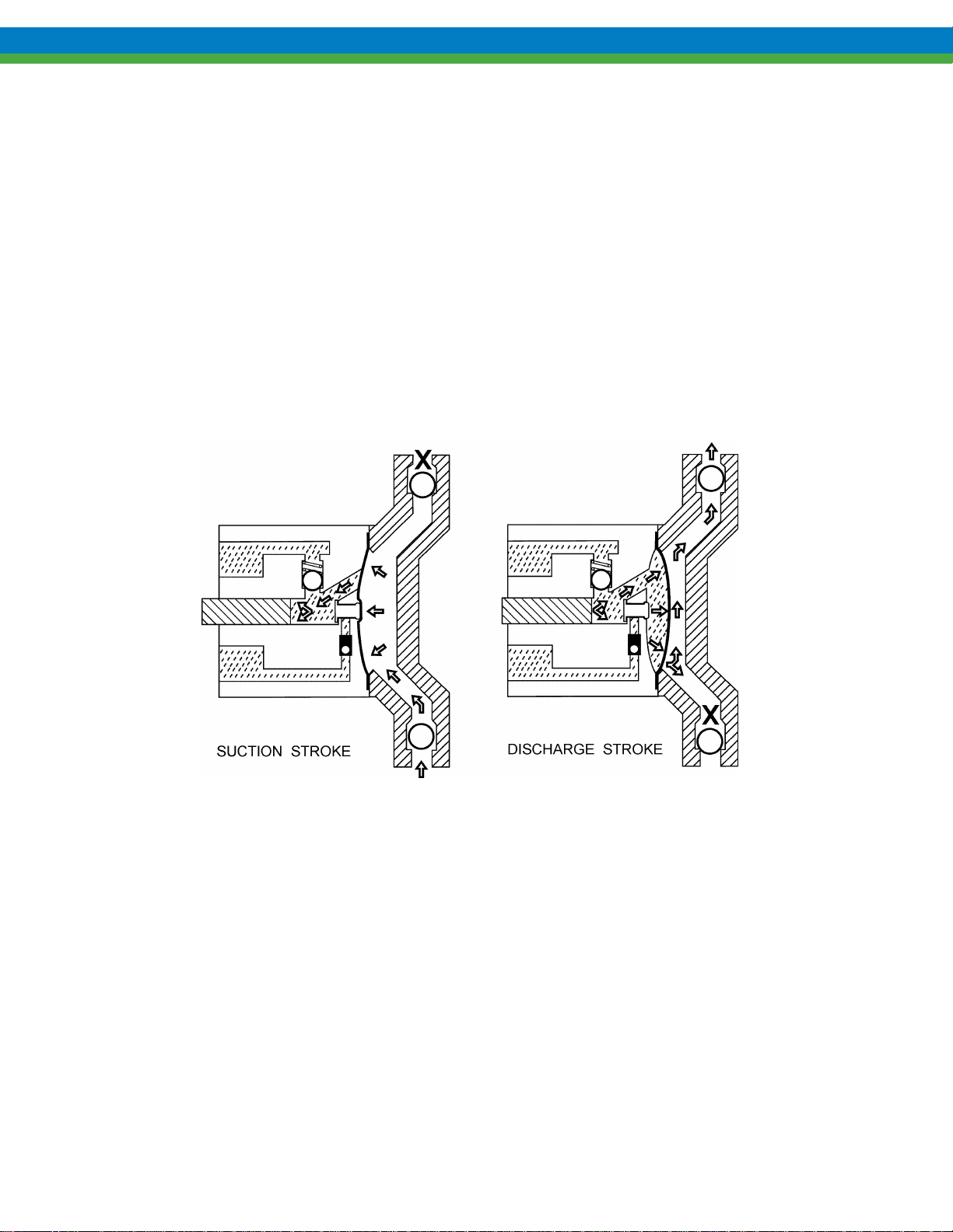
Figure 1
A piston reciprocates within an accurately sized cylinder at a preset stroke length, displacing an exact
volume of fluid. This piston does not pump chemicals: it pumps hydraulic oil. The piston and
associated mechanisms are enclosed in the eccentric box that also serves as a hydraulic oil reservoir. A
diaphragm separates the oil from the product pumped. The diaphragm moves in exact response to
piston displacement. The diaphragm does no work, and acts only as a separator. Consequently, oil
displacement is translated into equal product displacement. Piston retraction causes the product to enter
through the suction check valve. Piston advance causes the discharge of an equal amount of the product
through the discharge check valve.
1
Page 7
2.2 Component Location and Operation
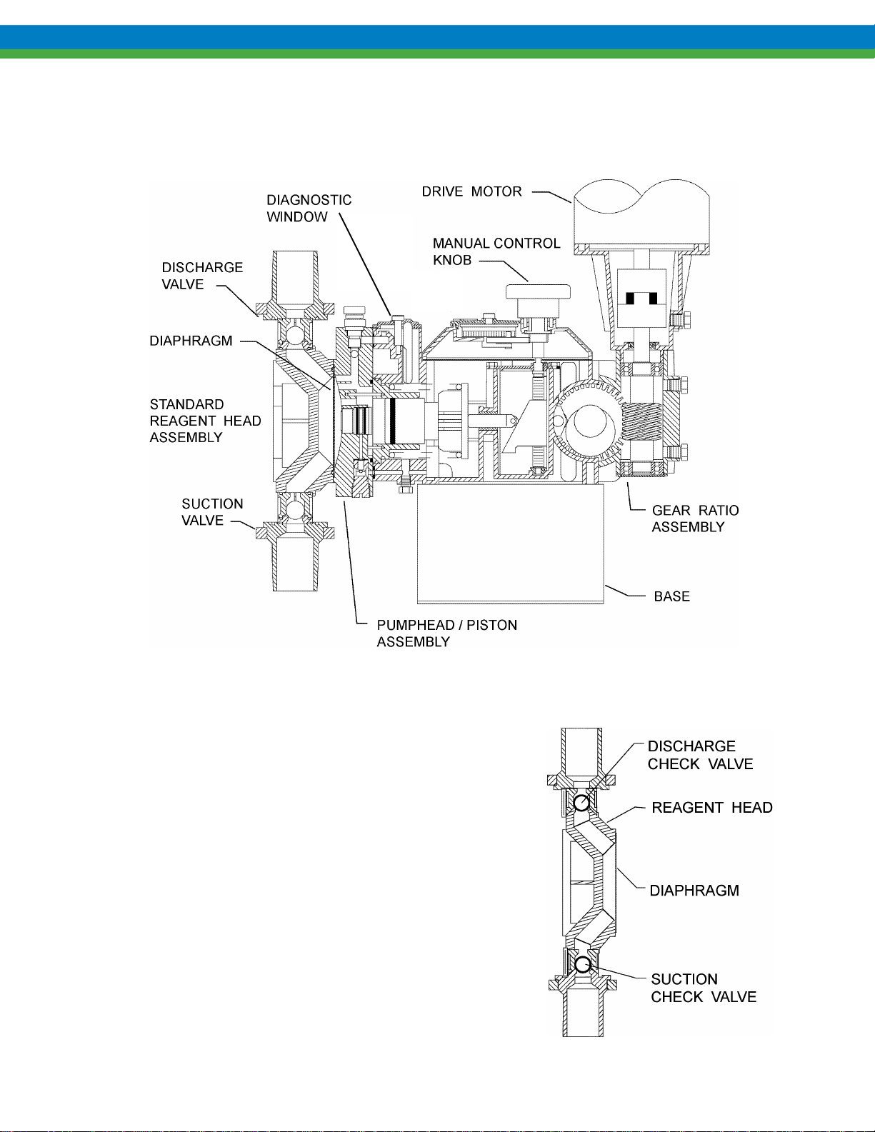
2.2.1 Reagent Head Assembly
The typical reagent head assembly consists of reagent head,
diaphragm, and suction and discharge check valves. This
assembly is the only part of the pump to contact the process
liquid; consequently, maintenance is critical to pump
performance.
Figure 2
Figure 3
2
Page 8
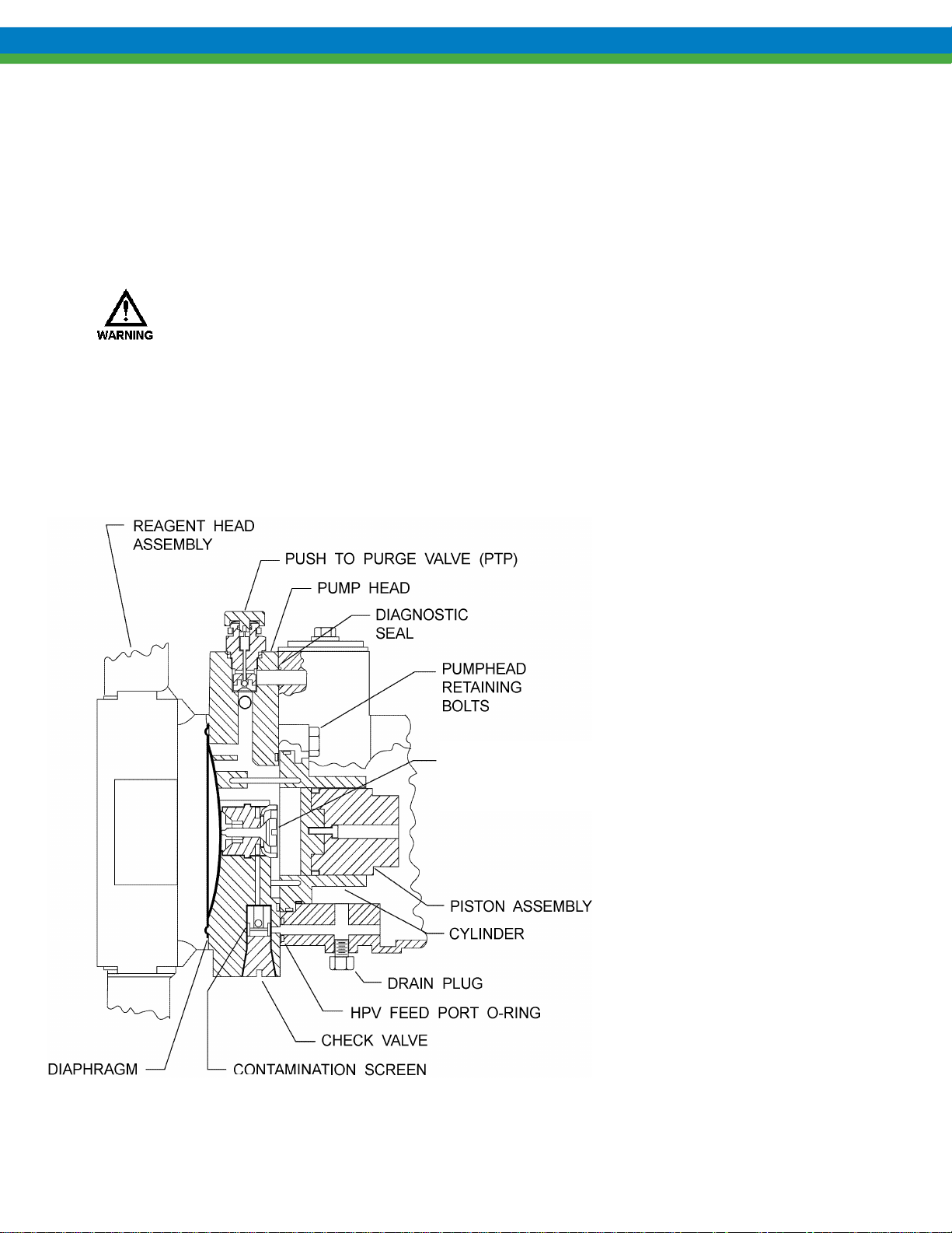
Figure 4
PULSAlarm Leak Detection
The PULSAlarm leak detection reagent head assembly consists of reagent head, leak detection
diaphragm, suction and discharge check valves, vacuum bleed port, and optional pressure switch and
gauge. If your pump is equipped with this option, refer to Appendix I on page 33 for further
information.
A sealed system must be maintained at all times during pump operation, whether leak
detection is required or not. If the proper level of vacuum, between 10 in and 26 in. (250mm to
650mm) Hg, or a sealed pressure system is not present, decreased flow and/or diaphragm
damage will occur. Please note that the factory setpoint for actuation of the vacuum switch is 6
in (152mm) Hg (vacuum) or 5 psig (pressure).
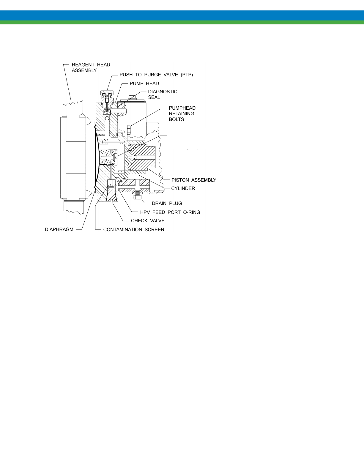
2.2.2 Pump Head/Piston assembly
HYDRAULIC
PERFORMANCE
VALVE (HPV)
The pump head/piston assembly is
installed on the eccentric box. This
assembly contains the hydraulic
system consisting of the pump head,
cylinder, piston assembly, and three
hydraulic valves:
PTP (Push-To-Purge)
HPV (Hydraulic Performance Valve)
HBV (Hydraulic Bypass Valve).
The PTP valve is situated at the top
of the pump head and automatically
removes gases from the hydraulic
system during normal operation.
Momentary manual actuation of the
external valve button overrides
automatic operation to validate
priming or to determine diaphragm
integrity.
The HPV automatically maintains the
required hydraulic oil volume by
replacing any oil lost past the piston
or through the PTP valve.
The HBV protects the pump from
over-pressurizing by relieving any
excess pressure in the pump’s
hydraulic system.
3
Page 9
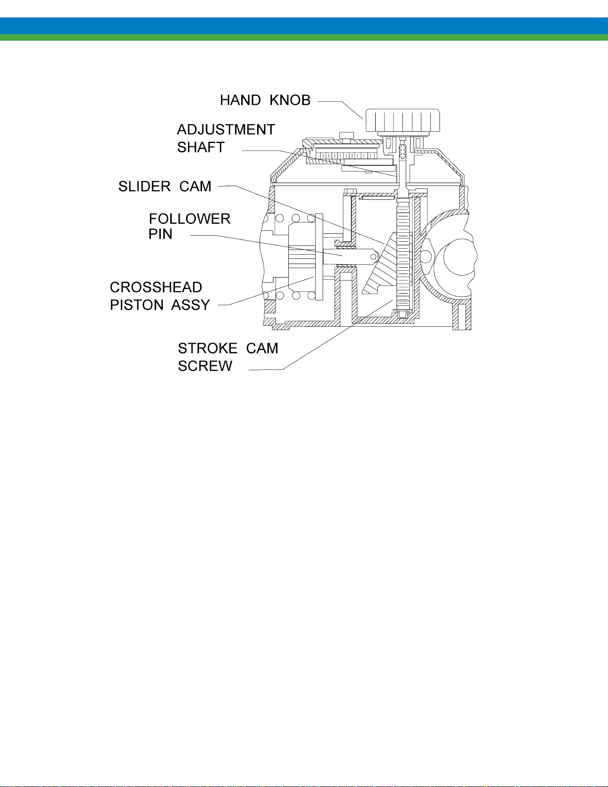
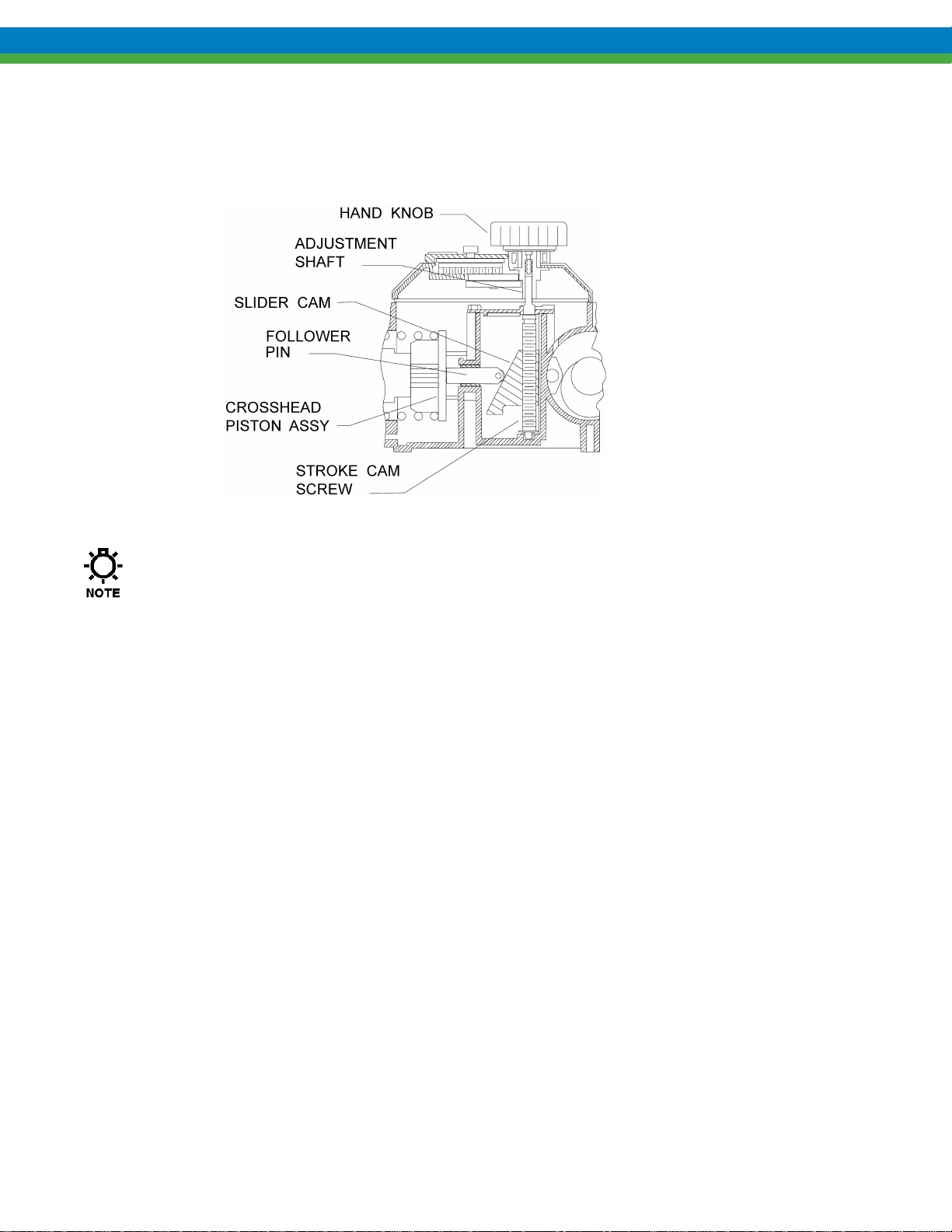
2.2.3 Control Assembly
Figure 5
PULSAR pumps incorporate a lost motion style of stroke length adjustment to limit piston travel
during the suction portion of each stroke. The stroke length setting is denoted by a (0 - 100) scale
located on the top of the unit.
Stroke is changed by depressing and turning the hand knob. This turns a screw which locates a slider
cam to position the follower pin as to limit the rearward travel of the piston. If the control cover is
removed and replaced, the bolts should be tightened to 20-24 In-lb (225 – 270 N-cm).
PULSAR pumps may also be equipped with the Pulsafeeder DLC or DLCM electronic stroke length
controllers. These allow for local and/or remote automatic control over stroke length (DLC) or stroke
length and motor speed (DLCM). Pumps equipped with the DLC or DLCM controllers are provided
with separate instructions for the controller. Refer to the appropriate Installation, Operation and
Maintenance Manual (IOM-PS-DLC-1101 or IOM-PS-DLCM-1101).
Some PULSAR pumps may also be equipped with the MPC control which allows for pump flow
control over a wide range via a specially designed variable speed drive. The MPC Installation,
Operation and Maintenance manual IOM-MPC-0104 covers information specific to this type of
control and should be consulted prior to operating the pump or the controller.
4
Page 10
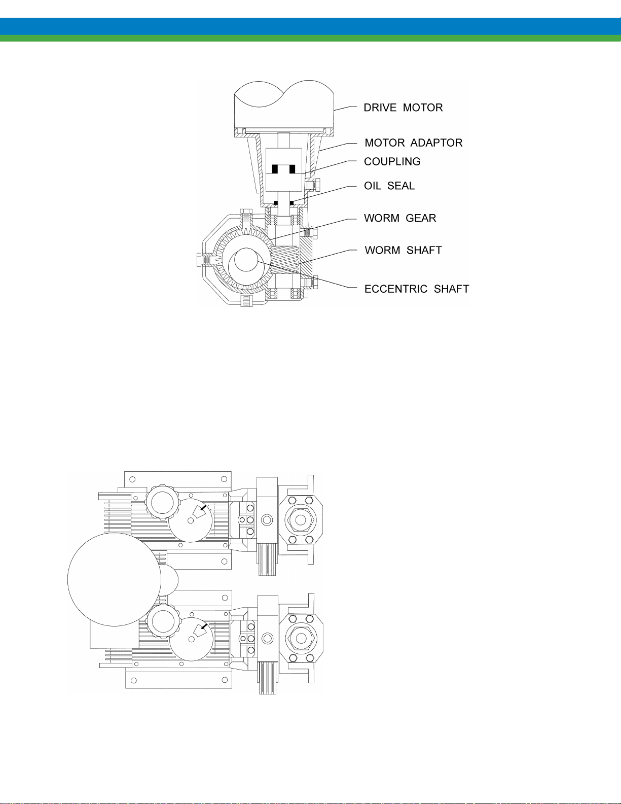
2.2.5 Gear Ratio Assembly
Figure 6
PULSAR pumps are driven by a standard C-face electric motor mounted on the motor adaptor input
flange. The motor drives a set of worm gears which convert rotational speed into torque. They in
turn power the eccentric shaft assembly that converts rotary motion to reciprocating motion. The
motor adaptor is available in a variety of configurations to accommodate different motor frame
specifications.
Figure 7
More than one pump can be driven through a single
drive assembly. This is referred to as multiplexing.
The pumps are mounted on a common gear reducer
assembly on the driver pump and the pump without
a gear reducer is called the driven pump. Each
pump is mounted on its respective standard simplex
base.
Whenever pumps are multiplexed, the eccentric
shafts are positioned to place a uniform load on the
driver. Before full disassembly always note the
relative positions of the eccentric shafts to each
other so they can be reassembled in the same
orientation.
5
Page 11

3. Equipment Inspection
Check all equipment for completeness against the order and for any evidence of shipping damage.
Shortages or damage should be reported immediately to the carrier and your Pulsafeed er rep rese ntat iv e.
3.1 Storage Instructions
3.1.1 Short Term
Storage of PULSAR pumps for up to 12 months is considered short-term. The recommended shortterm storage procedures are:
a) Store the pump indoors at room temperature in a dry environment.
b) Within two months after date of shipment, fill the eccentric box to its normal operating level with
PULSAlube 7H (purple) hydraulic oil. If required by the operating environment, take steps to
prevent entry of water or humid air into the eccentric enclosure.
c) Prior to start up, inspect housing, and gearbox. Replenish hydraulic and gearbox oils as required
to maintain operating levels. If water or condensation is present, change oil as described under
Equipment Startup.
d) Start up in accordance with instructions in this manual.
3.1.2 Long Term
Every twelve months, in addition to the above short-term procedures, power up the motor and operate
the pump for a minimum of one hour. It is not necessary to have liquid in the reagent head during
this operation, but the suction and discharge ports must be open to atmosphere. If the pump is
equipped with a PULSAlarm vacuum leak detection system, ensure that a vacuum is drawn before
operating the pump. See Appendix I on page 33 for more information.
After twelve months of storage, Pulsafeeder’s warranty cannot cover such items which are subject to
deterioration with age such as seals and gaskets. If the pump has been in storage longer than 12
months it is recommended that such items be inspected and replaced as necessary prior to startup.
Materials and labor to replace this class of item under this circumstance are the purchaser’s
responsibility. For a continuance of the warranty after extended storage, equipment inspection and
any required refurbishing must be done by a Pulsafeeder representative.
4. Installation
4.1 Location
When selecting an installation site or designing a skid package, consideration should be given to access
for routine maintenance.
PULSAR pumps are designed to operate indoors and outdoors, but it is desirable to provide a hood or
covering for outdoor service. External heating may be required if ambient temperatures below -18° C
(0° F) are anticipated. Check with the factory regarding suitability of the operating environment.
The pump must be rigidly bolted to a solid and flat foundation to minimize vibration, which can loosen
connections. When the pump is bolted down, care must be taken to avoid distorting the base and
affecting alignments. The pump must be level within 2°. This will assure that the hydraulic and g ear
oils are maintained at the proper levels and that the check valves can operate properly.
6
Page 12
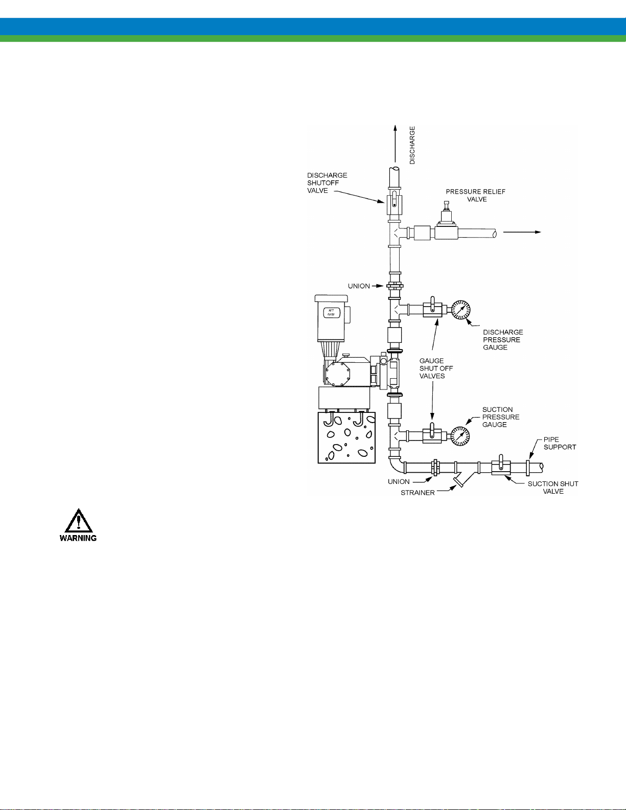
4.2 Piping System
All piping systems should include:
1. Shutoff valves and unions (or flanges) on
suction and discharge piping. This
permits check valve inspection without
draining long runs of piping. Shutoff
valves should be of the same size as
connecting pipe. Ball valves are
preferred since they offer minimum flow
restriction.
2. An inlet strainer, if the product is not a
slurry. Pump check valves are
susceptible to dirt and other solid
contaminants unless designed for that
service, and any accumulation can cause
a malfunction. The strainer should be
located between the suction shutoff valve
and the pump suction valve. It must be
sized to accommodate the flow rate and
the anticipated level of contamination.
100-mesh screen is recommended.
3. Vacuum/pressure gauges in the suction
and discharge lines in order to check
system operation. Gauges should be
fitted with protective shutoff valves for
isolation while not in use.
4. A separate system relief valve to protect
piping and process equipment, including
the pump, from excess process pressures.
Figure 8
The hydraulic bypass valve (HBV) in the pump is not intended to protect the system!
Piping weight must not be supported by the valve housings or other portions of the reagent head, as the
resulting stresses can cause leaks. If appropriate, provide for thermal expansion and contraction so that
no excess force or moments are applied to the pump.
In piping assembly, use a sealing compound chemically compatible with the process material.
Users of sealing tape are cautioned to ensure that the pipe thread ends are not taped. Both new and
existing piping should be cleaned, preferably by flushing with a clean liquid (compatible with process
material) and blown out with air, prior to connection to the pump. Flow issues at pump startup are often
related to the check valves being fouled with piping and process debris.
7
Page 13
4.3 Suction Pressure Requirements
Although PULSAR metering pumps have suction lift capability, all pump installations should have
minimum lift for optimum performance. A flooded suction (i.e., suction pressure higher than
atmospheric pressure) is preferable whenever possible. The pump should be located as close as possible
to the suction side reservoir or other source. Piping should be sized to allow for best possible NPSH
conditions.
It is not recommended to install a PULSAlarm equipped pump in a suction lift system.
If suction lift is required, the net positive suction pressure required (NPSHr) is 0.21 bar (or 3 psia). If
this requirement is not met the process liquid may cavitate inside the pump, degrading metering
accuracy. To maintain prime on a suction installation, a foot valve is required. In addition, suction
pressure must be maintained at a minimum absolute value of 0.35 bar (or 5 psia) to ensure proper
hydraulic system and proper pump operation.
The maximum inlet pressure is limited to 30 psig with the standard composite diaphragm. Higher
suction pressures may be accommodated with optional diaphragm configurations.
It is critical that PULSAR pumps have free flowing and unobstructed suction conditions at all
times. Closed valves, clogged strainers, obstructed piping, etc, are to be avoided. Suction
restrictions can place stress on the diaphragm that may result in premature failure.
Refer to Appendix II for procedures for the calculation of suction pressure.
4.4 Discharge Pressure Requirements
All PULSAR Metering Pumps are designed for continuous service at the rated discharge pressure. If
system suction pressure were to exceed system discharge pressure (a condition sometimes described as
“pumping downhill”), flow would be generated in addition to that caused by the pump, resulting in a
reduction in accuracy and loss of control over the metering process. To prevent this condition,
commonly referred to as “flow-through”, discharge pressure must exceed suction pressure by at least
0.35 Bar (or 5 psi). This can be achieved where necessary by the installation of a backpressure valve in
the discharge line.
Discharge systems should be protected from excessive pressures by utilizing a pressure relief or
pressure limiting valve in the piping system. Operation of the pump at pressure above its nameplate
rated maximum may result in damage to the pump components and/or unsafe system conditions.
Refer to Appendix II for procedures for the calculation of discharge pressure.
4.5 Automatic Control (DLC, DLCM or MPC)
Pumps equipped with the electronic controllers are provided with separate instructions. Refer to DLC
manual IOM-PS-DLC-1101, DLCM manual IOM-PS-DLCM-1101, or MPC manual IOM-MPC-0104.
Perform all DLC, DLCM or MPC installation procedures prior to pump startup.
8
Page 14

4.6 PULSAlarm Leak Detection Electrical Connections
Pressure
Gauge
Figure 9
If equipped with an optional vacuum or pressure switch, install electrical wiring and conduit in
accordance with local electrical codes.
The switch is rated as follows:
30 VDC or 125 VAC 1 Amp er e R es is t iv e .
The switch is the SPDT (single pole, double throw) type and can therefore be connected to either open
or to close upon detection of diaphragm leak condition. Contacts or wires are identified as follows:
Normally Open (NO) wire color WHITE
Normally Closed (NC) wire color RED
Common (Com) wire color BLACK
THE ENCLOSURE IS LABELED WITH APPLICABLE SAFETY AGENCY RATINGS FOR HAZARDOUS
AREA INSTALLATION
NEVER QUALIFY AS NON
TERM HAZARDOUS AREA USE. PROTECTION MUST BE PROVIDED BY THE ENCLOSURE.
. SINCE THE SWITCH IS OF THE MECHANICAL CONTACT TYPE, IT CAN
-SPARKING (NON-INCENDIVE, OR “M”) FOR OCCASIONAL AND SHORT-
9
Page 15
Oil
Color
Application
Amount (approx.)
PULSAlube 7H
Purple
Eccentric Housing
1000 ml (1 quart) NP980002-005
PULSAlube 8G
Amber
P25H Series Gearbox
150 ml (0.16 quart)
P55H Series Gearbox
200 ml (0.21 quart) NP980001-002
5. Equipment Setup
5.1 Lubrication
PULSAR pumps use two separate oils: PULSAlub e 7H, hyd raul ic oil for the e ccent ri c box and
PULSAlube 8G, gear oil for the gearbox. Confusion between the two will impair performance and
damage the pump.
PULSAR pumps are shipped from the factory with the Eccent ric Hou sing d r ained, and th e Gear box
full. The Installer should fill the Eccentric Housing. The external gearcase does not need to be
checked.
5.1.1 Oil Capacities
PULSAlube 7H hydraulic oil is now available in 1 liter containers (previously 1.5 liters).
PULSAlube 8G gear oil is available in 200 ml containers.
It is recommended that adequate supplies of both PULSAlube oils be on hand for periodic changes
and emergency requirements. The approximate amounts of oil required to fill PULSAR pumps to
specified levels are:
Please note that the eccentric box section of the pump is not completely full when the proper amount
of oil is used, this is normal. Starting in production year 2007, Pulsafeeder will distribute
PULSAlube 7H in 1 liter containers to facilitate proper oil fill.
5.1.2 Gear Oil Fill
In all pump configurations, one pipe plug is present at the top of the gearbox and one is on the side at
the centerline level. Remove the top plug and fill with PULSAlube 8G (amber) gear oil through the
top port to the level of the eccentric shaft centerline, which is level with the side port. If desired, the
side plug can be removed so that leakage from the side port indicates attainment of the required level.
Replace both pipe plugs after filling. Do not add oil through the port on the side of the motor adapter,
as this port is for motor drive coupling access only.
10
Page 16
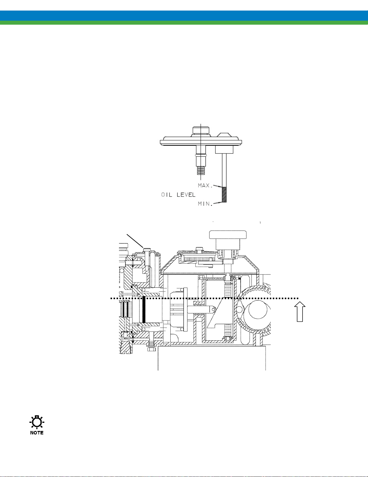
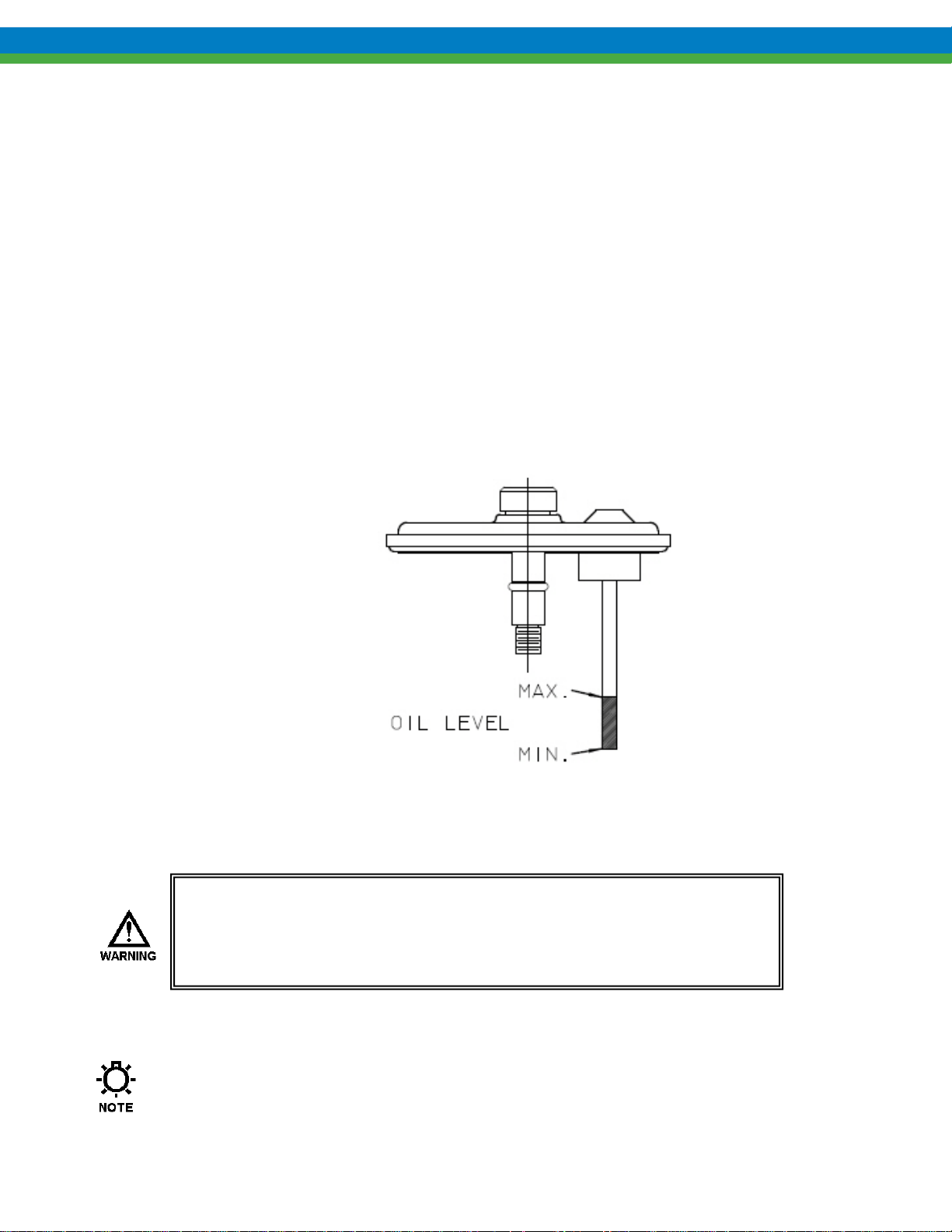
5.1.3 Hydraulic Oil Fill
Remove the diagnostic window to gain access to the reservoir and add PULSAlube 7H hydraulic oil
until the oil level is between the max and min as indicated on the new (flexible style) dipstick as
illustrated below. For older pumps equipped with a solid dipstick, the oil level should be below the
upper coils of the piston return spring, if the upper coils of the spring are submerged, the oil level is
too high (ref. Figure 10). Adding 1 liter (approx. 1 quart) of oil to a fully drained pump will result in
the correct fill level. High oil level will not affect the operation of the pump, however it can result in
nuisance leakage of oil. Replace the window, making sure it is properly aligned and square before
tightening the thumbscrew.
DIAGNOSTIC COVER
(FOR OIL FILL)
MAXIMUM
FILL
Figure 10
5.2 PULSAlarm Leak Detection
Refer to Appendix I, page 33 for startup instructions specific to pumps equipped with the PULSAlarm
diaphragm leak detection system
11
Page 17
Drive Motor Installation
5.2.1 Motor Rotation
Motor can be operated in either direction, clockwise or counterclockwise. Verification of motor
direction is not necessary at startup.
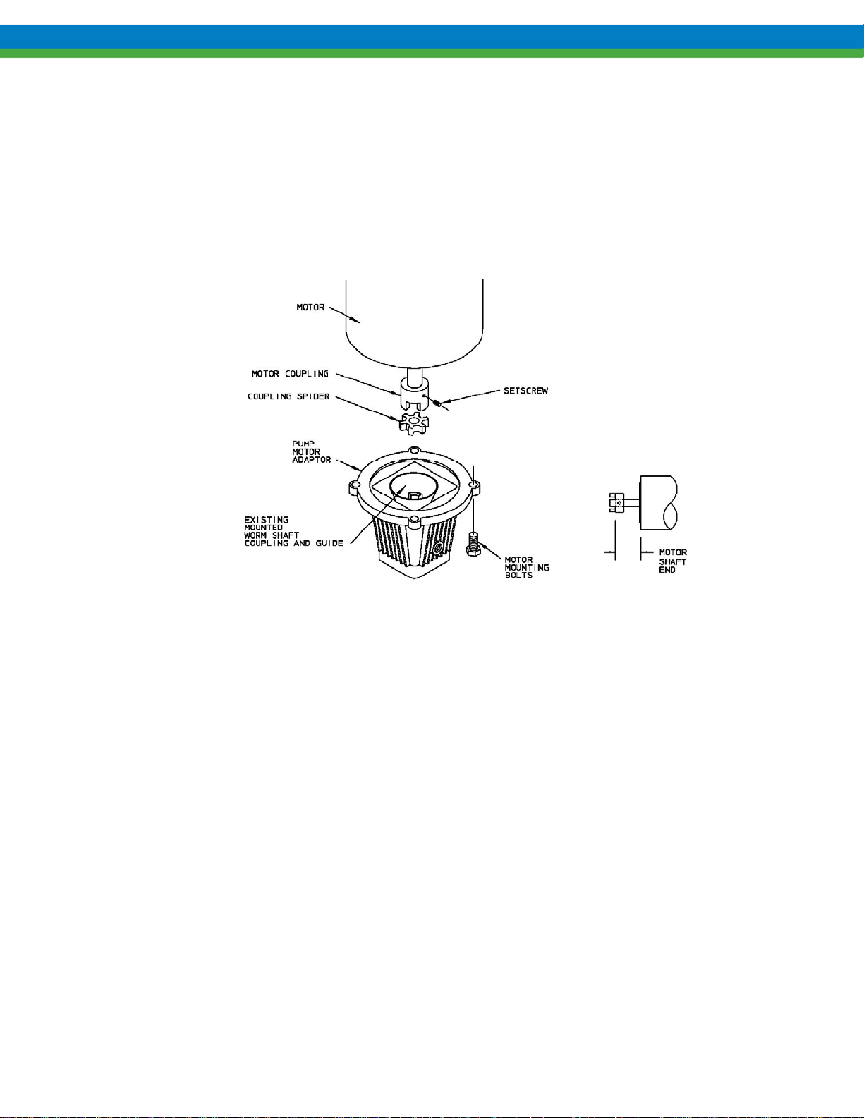
5.2.2 Motor Installation
PULSAR pumps may be shipped with the drive motor packed separately. This is done to avoid damage
during transport.
1. Remove the unattached coupling half from the motor adaptor. Ensure that the elastomer
coupling spider remains in place, on the coupling half that remains attached to the worm shaft.
2. If applicable, remove any tape or retainer rings that hold the motor shaft key in place.
3. Place the loose coupling half on the motor shaft. Align the keyway with the key and align shaft
end to inner coupling surface as shown in figure above.
4. Tighten the setscrew onto the shaft key.
5. Place the motor in a vertical position and align the coupling teeth.
6. Install the motor downwards onto the adaptor. The plastic guide will assist in aligning the
coupling halves. Final position can be achieved by slightly rotating the motor until the coupling
jaws align.
7. Rotate the motor until the clearance holes in the adaptor and the tapped holes in the motor align.
Fasten the motor to the adaptor using the supplied bolts (4). Tighten bolts evenly to secure
motor.
5.2.3 Electrical
Wire the PULSAR drive motor according to the motor vendor’s nameplates and instructions, and
according to any appropriate national and local electrical codes and regulations.
If the motor is to be utilized with a Pulsafeeder controller, such as the DLC, DLCM, or MPC,
consult the appropriate Pulsafeeder IOM for further motor wiring instructions.
Figure 11
12
Page 18

6. Startup Procedure
6.1 Output Adjustm ent
Figure 12
All PULSAR pumps have a hand-wheel for manual stroke length adjustment. Mounted atop the
eccentric box, the hand-wheel can be adjusted at any point (from 0 to 100% stroke setting) by pressing
down and then rotating the hand wheel as required. Stroke length is locked during operation to prevent
drift: pressing the hand-wheel down temporarily disengages the lock for adjustment; release after
adjustment automatically resets the lock at the new setting. An indicator adjacent to the hand-wheel
displays the output setting. Adjustments can be made while the pump is at rest or operating, although
operating adjustments are easier to make. Manual adjustment serves as a backup for pumps provided
with an optional DLC stroke length controller. If the control cover is removed and replaced, the bolts
should be tightened to 20-24 In-lb (225 – 270 N-cm).
If the pump is equipped with a vacuum leak detection system, vacuum must be maintained at
all times during pump operation, whether or not leak detection is required. If the proper level
of vacuum (between 10 in and 26 in. (250mm to 650mm) Hg) is not present, decreased flow
and/or diaphragm damage will occur. See Appendix I on page 33 for further information.
If the pump is equipped with a pressure leak detection system, the system must remain sealed at
all times during pump operation, whether or not leak detection is required. If the seal is broken,
decreased flow and/or diaphragm damage will occur. See Appendix I on page 33 for further
information.
Leak Detection Diaphragm syste ms require special hydraulic pri ming cons id erat ion s to prote ct
the diaphragm from damage during initial pump startup. See Appendix I on page 33 for further
information.
13
Page 19

6.2 Suction System
Before operation of any PULSAR pump, carefully ensure that all suction valves are in the open position.
Verify that all filters and strainers are clean and clear. Ensure that any other potential causes of
restriction have been addressed. Unrestricted flow of liquid to the suction side of the pump is critical to
proper operation.
6.3 Priming the Pumphead (Hydraulic System)
All pumps are shipped with a fully primed hydraulic system. However, during shipping and handling
some air may enter the hydraulic system. Generally this air will be automatically purged after a short
run-in period. If necessary, rapid purging may be accomplished by fully depressing and holding the
PTP valve while the pump is operating. With the valve depressed, oil should begin to flow out of the
center diagnostic port. Continue to hold the valve down until the oil is clear of bubbles.
If the pump fails to prime, go to the next section and follow the Priming the Pumphead procedure
(Section 7.2.2). See Appendix I on page 33 for further information if your pump is equipped with a
PULSAlarm leak detection system.
6.4 Priming the Reagent Head (Product System)
1. Open the suction and discharge line shutoff valves.
2. If the piping system design and the storage tank are such that the product flows due to gravity through
the pump, no priming is required. In the event the discharge line contains a significant amount of
pressurized air or other gas, it may be necessary to lower the discharge pressure to enable the pump to
self-prime.
3. If the installation involves a suction lift, it may be necessary to prime the reagent head and suction
line. Try priming the reagent head first. Remove the discharge valve by unscrewing the four tie bar
bolts and removing the valve as a unit. Fill the head through the discharge valve port with process (o r
compatible) liquid, then reinstall the valve and retighten the tie bar bolts.
4. Start the pump at the 0% stroke length setting and slowly increase the setting to 100% to prime the
pump. If this does not work, it will be necessary to fill the suction line.
5. Filling of the suction line will necessitate the use of a foot valve or similar device at the end of the
suction line so that liquid can be maintained above the reservoir level. Remove the suction valve
assembly, fill the line, replace the valve, then remove the discharge valve assembly and fill the
reagent head as described in Step (3) above. The pump will now self-prime when started up per step
(4) above.
14
Page 20

6.5 Calibration
All metering pumps must be calibrated in order to accurately specify stroke length settings for required
flow rates. For pumps provided with DLC or DLCM electronic stoke length control, refer to separate
instructions as noted on page 8.
Figure 13
A typical calibration chart is show n in Figure 13. Although output is linear with respect to stroke
length setting, an increase in discharge pressure decreases output uniformly, describing a series of
parallel lines, one for each pressure (only two are shown).
The theoretical output flow rate at atmospheric output pressure is based on the displacement of the
hydraulic piston (the product of piston cross-sectional area and stroke length ) and the strok ing rate of
the pump. With increasing discharge pressure there is a corresponding decrease in output flow of
approximately 1% per 7 bar (100 psig) increase in output pressure. Whenever possible, calibration
should be performed under actual process conditions (i.e., the same or a similar process liquid at system
operating pressure).
To assure a sound hydraulic system, run the pump for 10-15 minutes prior to calibration. This will
allow the PTP (automatic bleed) valve to purge any air from the system.
To construct a calibration chart, measure the flow rate several times at three or more stroke settings (i.e.,
25, 50, 75, and 100), plot these values on linear graph paper, and draw a best-fit line through the points.
For stable conditions, this line should predict settings to attain required outputs.
Checking the actual flow rates is especially important in pumps producing low flow rates and operating
against high discharge pressures. In this type of system, normal losses of efficiency can result in lack of
measurable flow at shorter piston stroke lengths. This is a function of the system conditions and does
not indicate a problem with the pump. Careful measurement of actual pump flow at several test points
will allow for proper calibration over the complete flow range.
15
Page 21

PTP port
Bypass port
6.6 Checking the Diagnostic Window
(side)
Connected to The hydraulic bypass valve on
the side of the pump head
Function Bypass protects the pump from
excessive pressure and hydraulic
upset conditions
Normal operation No oil should move through this
port when the pump is operating
normally
Abnormal operation Oil is seen flowing from the port No oil moving through the port
Bypass Port PTP Port
(center)
The PTP push-button valve on
the top of the pump head
Allows any air trapped in the
hydraulic system to escape
Small amount of oil will weep
from port during operation,
flow increases if PTP button is
depressed
at any time, or product (not oil)
is seen
Things to check if
abnormal operation is
suspected
o Discharge pressure too high
o Bypass valve setpoint too low
o Bypass valve malfunction
o Other upset condition
16
o PTP damaged
o HPV filter screen clogged
o HPV not operating properly
o Diaphragm damaged
Page 22

7. Maintenance
BEFORE PERFORMING ANY MAINTENANCE REQUIRING REAGENT HEAD OR VALVE (WET END)
DISASSEMBLY
HAZARDOUS PROCESS MATERIALS ARE INVOLVED
AND THE ENVIRONMENT BY CLEANING AND CHEMICALLY NEUTRALIZING AS APPROPRIATE
WEAR PROTECTIVE CLOTHING AND EQUIPMENT AS APPROPRIATE.
Accurate records from the early stages of pump operation will indicate the type and levels of required
maintenance. A preventative maintenance program based on such records will minimize operational
problems. It is not possible to forecast the lives of wetted parts such as diaphragms and check valves.
Since corrosion rates and operational conditions affect functional material life, each metering pump must
be considered according to its particular service conditions.
PULSAR KOPkits contain all replacement parts normally used in a preventative maintenance program. It
is recommended that KOPkits and PULSAlube hydraulic and gear oils be kept available at all times.
Each PULSAR pump is provided with an individual specification data sheet included in the parts list
package. The data sheet contains important information relating to the application along with pump serial
number, pump specifications (i.e., materials, piston size, stroking rate, etc.).
, BE SURE TO RELIEVE PRESSURE FROM THE PIPING SYSTEM AND, WHERE
, RENDER THE PUMP SAFE TO PERSONNEL
.
7.1 Oil Changes
The recommended oil change intervals are dependent upon the operating environment and level of
pump usage, classified as follows:
1. Normal service: clean/dry atmosphere, an ambient operating temperature of 0° C to 40° C (32° F to
104° F) and up to 2,000 annual operating hours.
2. Severe Service: humid atmosphere, an ambient operating temperature below 0° C (32° F) or above
40° C (104° F), and over 2,000 annual operating hours.
7.1.1 Gear Oil Change:
The recommended gear oil change interval is five years for normal service and two years for severe
service.
Gear Oil change procedure is as follows:
1. Disconnect the power source to the drive motor.
2. Relieve all pressure from the piping system.
3. Remove the fill plug from the top of the gearbox.
4. Drain the oil by removing the drain plug on the bottom of the gearbox.
5. Replace the drain plug.
6. Refill with fresh PULSAlube 8G (amber) gear oil (refer to Gear Oil Fill, Section 5.1.2).
7. Replace the top fill plug and side plug (if removed).
17
Page 23
7.1.2 Hydraulic Oil Change:
The recommended hydraulic oil change interval is 2 years for normal service and 1 year for severe
service.
Hydraulic Oil change procedure is as follo ws:
1. Disconnect the power source to the drive motor.
2. Relieve all pressure from the piping system.
3. Remove the diagnostic window from the top of the eccentric box.
4. Drain the oil by removing the drain plug on the bottom of the eccentric box.
5. Remove and clean the HPV check valve screen (refer to Check Valve Screen – Removal and
Cleaning, Section 7.4.2).
6. Replace the drain plug.
7. Fill the eccentric box with PULSAlube 7H (purple) hydraulic oil (refer to Hydraulic Oil Fill,
Section 5.1.3). Proper fill of a fully drained pump requires 1 liter (approx. 1 quart) of
PULSAlube 7H oil.
8. Replace the diagnostic window.
7.2 Wet End Removal, Inspection, and Reinstallation
If the diaphragm has failed, process material may have contaminated
the pump hydraulic oil. Handle with appropriate care, clean and
replace oil if required.
PULSAlarm Leak Detection System
See Appendix I, page 32 for information on maintenance of the PULSAlarm Leak Detection diaphragm
18
Page 24

7.2.1 Standard Diaphragm Repla c e m ent
Figure 14
PULSAR diaphragms do not have a specific cycle life; however, the accumulation of foreign material
or the entrapment of sharp particles between the diaphragm and dish cavity can eventually cause
failure. Failure can also occur as a result of hydraulic system malfunction or chemical attack.
Periodic diaphragm inspection and replacement are recommended.
Diaphragm Replacemen t Procedu r e:
1. Disconnect the power source to the drive motor
2. Relieve all pressure from the piping system.
3. Take all precautions to prevent environmental and personnel exposure to hazardous materials.
4. Close the inlet and outlet shutoff valves.
5. Place a suitable container underneath the pump head to catch any liquid leakage.
6. Disconnect piping to the reagent head and drain any process liquid, following material safety
precautions described.
7. Remove all but one top reagent head bolt. Oil will leak out between the pump head and reagent head
as the bolts are loosened.
8. Tilt the head and pour out any liquids retained by the check valves into a suitable container,
continuing to follow safety precautions as appropriate.
9. Remove the final bolt and rinse or clean the reagent head with an appropriate material.
10. Remove and inspect the diaphragm. It may have taken a permanent convex/concave set as a result of
normal flexure and conformance to the dishplate. This condition is normal and is not cause for
replacement. The diaphragm must be replaced if it is deformed, dimpled, or obviously damaged.
11. To install a diaphragm, first ensure that the critical sealing areas of diaphragm, reagent head, and
pump head are clean and free of debris. Set the diaphragm in place on the reagent head and ensure
seating of the diaphragm sealing ring into the mating groove in the reagent head.
12. Install the reagent head bolts and tighten in an alternating pattern to ensure an even seating force.
Torque to the values recommended in Appendix IV.
13. Re-prime the pump head, see Section 7.2.2.
When reinstalling a used diaphragm it is not necessary to maintain the previous orientation relative
to the reagent head or pump head hole pattern.
19
Page 25
7.2.2 Re-Priming the Pumphead
HYDRAULIC
PERFORMANCE
VALVE (HPV)
Leak Detection diaphragm systems
require special hydraulic priming
considerations to protect the
diaphragm from damage during
initial pump startup. Refer to
Appendix I, page 33 and review these
procedures carefully before restarting a PULSAR pump equipped
with a leak detection system.
Figure 15
Hydraulic Priming Procedure, for standard Composite (THY) and Solid (PTFE) diaphragms:
1. Disconnect the power source to the drive motor.
2. Relieve all pressure from the piping system and where possible allow liquid to enter the reagent
head assembly.
3. Remove the diagnostic window and fill the eccentric box with PULSAlube 7H hydraulic oil to the
proper level. Replace the diagnostic window.
4. Turn on the pump and adjust the stroke length to the maximum setting of 100%.
5. Fully depress and hold the PTP valve. After several minutes oil should begin to flow out of the
center diagnostic port. Continue to hold the valve down until the oil is clear of bubbles. The
pump is now primed. If oil fails to flow out of the diagnostic port, proceed to step 6.
6. Reset to the zero stroke length setting, and turn off the pump. Setting the pump to zero stroke
moves the piston forward to prevent diaphragm damage at startup.
7. Remove the PTP valve from the pumphead. Using a small plastic funnel, slowly pour oil into the
pumphead through the PTP valve port until full.
8. Replace the PTP valve, ensuring that the flat copper gasket and o-ring are properly in place.
9. Turn on the pump. Gradually raise the stroke to the full 100% setting. Fully depress and hold the
PTP valve. Oil should begin to flow out of the center diagnostic port. Continue to hold the valve
down until the oil is clear of bubbles. If oil fails to flow out of the diagnostics port, then
additional oil is required in the pumphead: repeat steps (6) and (7) above.
20
Page 26

7.3 Check Valves
7.3.1 General Description
Most fluid metering problems are related to check valves. Problems usually
stem from solids accumulation between valve and seat, corrosion of seating
surfaces, erosion, or physical damage due to wear or the presence of foreign
objects.
The valve incorporates a ball, guide, and seat. Flow in the unchecked
direction lifts the ball off the seat, allowing liquid to pass through the guide.
Reverse flow forces the ball down, sealing it against the sharp edge of the
seat. The guide permits the ball to rotate but restricts vertical and lateral
movement in order to minimize “slip” or reverse flow. Ball rotation prolongs
life by distributing wear over the entire surface of the ball. Since ball return
is by gravity, the valve must be in the vertical position in order to function
properly. Parts are sealed by o-rings.
7.3.2 Removal, Inspection, a nd Re installation
Use the following procedure to remove, inspect and reinstall the check valves:
1. Disconnect the power source to the drive motor.
2. Relieve all pressure from the piping system.
3. Take all precautions to prevent environmental and personnel exposure to hazardous materials.
4. Close the inlet and outlet shutoff valves.
5. Loosen the suction valve tiebar bolts and spring the suction piping slightly to drain any liquid from
the reagent head cavity. If the piping is closely connected it may be necessary to disconnect a union
or flange.
6. Remove the suction check valve assembly (ball contained within guide and seat), holding it together
as a unit.
7. Loosen the tiebar bolts on the discharge valve and spring the piping slightly to drain any liquid.
8. Remove the discharge check valve assembly, holding it together as a unit as before.
9. Disassemble both valves and examine components for wear. Seats should have sharp edges or a
small chamfer, free from dents or nicks. Hold the ball firmly against its mating seat in front of a
bright light to inspect for fit.
Observation of light between ball and seat is cause for replacement of either or both components.
For best results, always loosen the unions or flanges on either side of the system pip ing prior to retightening of the check valve assemblies. Retighten the unions or flanges after the check valves are
securely tightened into position.
10. Reassemble both valves using new parts as required. Sealing o-rings should always be replaced.
11. Reinstall both valve assemblies, taking care to ensure that they are correctly oriented with balls above
seats.
12. Tighten the tiebar bolts evenly, making sure the valve assemblies are assembled squarely. Refer to
Appendix IV for torque values.
13. Check for leaks and retighten tiebar bolts as necessary.
20
Page 27
7.4 Hydraulic Performance Valve (HPV)
7.4.1 General Description
During normal pump operation hydraulic fluid is continually discharged through the automatic bleed
valve and may also be lost past the piston seals. This causes the diaphragm to be drawn further back on
each successive suction stroke until it actuates the HPV. Once the valve is actuated, oil is allowed to
flow into the hydraulic system until the piston reaches the end of the suction stroke. As the piston starts
forward a check valve prevents oil from flowing back through the HPV, thereby allowing the valve to
close as the diaphragm moves forward. Through this process the diaphragm is continually maintained
in a proper operating position relative to the pumphead dish-plate. Since the HPV is unaffected by the
vacuum level in the pumphead, oil cannot be inadvertently brought into the hydraulic system which
would result in over-extension and damage to the diaphragm. This feature provides pump protection
should the suction line become restricted or closed.
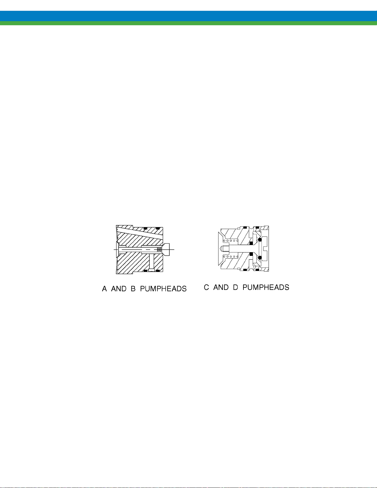
PULSAR pumps utilize two styles of High Performance Valves (refer to Figure 17) dependent on the
pumphead size. Although different in appearance they function identically. The valves are factory
preset and require no maintenance provided the hydraulic oil remains clean. The check valve in series
with the HPV includes a screen to trap contaminants (refer to Figure 15) and should be removed and
cleaned with each change of the hydraulic oil as indicated below. A clogged filter screen will impede
the operation of the HPV, and can lead to diaphragm damage. Should the HPV require removal for
cleaning or replacement, follow the procedure appropriate to the valve style. If a diaphragm has failed,
and chemical has contaminated the pump head assembly, both the HPV and the HPV check should be
removed and thoroughly cleaned.
Figure 17
7.4.2 Check Valve Screen - Removal and Cleaning
Use the following procedure to remove and clean the Check Valve screen (refer to Figure 15) It is
easiest to perform this process during an oil change:
1. Disconnect the power source to the drive motor
2. Relieve all pressure from the piping system.
3. Drain hydraulic fluid from the eccentric box.
4. Unscrew the check valve from the bottom of pump head.
5. Clean the valve and screen in a solvent compatible with the nitrile seal material and blow air through
the valve to remove all contaminants.
6. Inspect the copper gasket and o-ring for nicks or other damage and replace if necessary.
7. Lubricate the o-ring with PULSAlube 7H and replace the valve, tightening securely.
8. Re-install the eccentric box drain plug and refill with PULSAlube 7H hydraulic oil.
21
Page 28

7.4.3 HPV Removal and Replace m e nt - A & B Pumphead Style
Use the following procedure for a HPV Removal and Replacement (A & B Pumphead Style)
1. Remove the reagent head and diaphragm, and drain hydraulic oil from the eccentric box.
2. Remove the four bolts on the front eccentric box flange which retain the pumphead. The piston
return spring is under compression and will force the pumphead/cylinder away from the eccentric box
as the bolts are removed.
3. Remove the seal retainer nut from the pumphead cylinder (refer to Figure 18).
4. Remove the four socket head capscrews that retain the cylinder to the pumphead (refer to Figure 18)
and remove the cylinder, taking care to not lose the copper gasket.
5. Select a socket or spacer which fits into the cylinder side bore of the pumphead and also clears the
rear poppet of the HPV (refer to Figure 18).
6. Exert pressure on the socket or spacer to press the HPV out of the pumphead.
7. If cleaning of the valve is required, use a suitable solvent and blow air through the valve to remove all
contaminants.
8. Inspect the o-rings on the body of the valve for nicks or other damage and replace if required.
9. Lubricate the o-rings with PULSAlube 7H and carefully insert the HPV into the dish side bore of the
pumphead. Rotate the valve so that the hole and slot farthest from the center are aligned with the
corresponding slot in the pumphead. Using a socket or spacer which clears the front poppet, press the
valve into the pumphead until it is fully seated.
Figure 18
10. Reinstall the cylinder, copper gasket, and seal retainer nut.
11. Inspect the o-ring on the pumphead locating shoulder for nicks or other damage, replace if necessary,
and lubricate with PULSAlube 7H.
continues next page…
22
Page 29

12. Make certain that the diagnostics seal at the top of the eccentric box flange and the HPV feed port o-
ring at the bottom of the flange are in place (refer to Figure 4).
13. Insert the pumphead into the eccentric box using the locating pins as a guide.
14. Some compression of the piston return spring will be required in order to start the pumphead retaining
bolts after which the bolts can be tightened to complete installation of the head. Spring compression
will be minimiz e d with the ec centric in the retra cted position and the s tr oke setting at 100%.
15. Reinstall the diaphragm and reagent head.
16. Re-install the eccentric box drain plug and fill with PULSAlube 7H hydraulic oil.
17. Re-prime the pump.
7.4.4 HPV Removal and Replacement - C & D Pumphead Style
Use the following procedure for a HPV Removal and Replacement (C & D Pumphead Style)
1. Remove the reagent head and diaphragm.
2. Drain hydraulic fluid from the eccentric box.
3. Remove the four bolts on the front eccentric box flange which retain the pumphead. the piston return
spring is under compression and should force the pumphead/cylinder away from the eccentric box as
the bolts are removed. If the cylinder separates from the pumphead, remaining in the eccentric box, it
may be necessary to remove the eccentric box cover and tap out the cylinder from behind.
4. The cylinder is retained to the pumphead by two roll pins. Separate the cylinder by prying on the
groove above the o-ring (refer to Figu re 19).
5. Using a hex wrench, unscrew the HPV from the cylinder side of the pumphead.
6. If cleaning of the valve is required, use a solvent compatible with nitrile seals and blow air through
the valve to remove all contaminants.
7. Lubricate the o-rings with PULSAlube 7H and carefully insert the HPV into the back of the
pumphead, make certain that the threads are properly engaged before tightening.
8. Align the roll pins to the appropriate holes and press the cylinder onto the pumphead, make certain
that the o-ring on the back side of the pumphead is in place
Figure 19
23
Page 30

9. Inspect the o-ring on the cylinder locating shoulder for nicks or other damage and replace if
necessary, lubricate with PULSAlube 7H.
10. Make certain that the diagnostics seal at the top of the eccentric box flange and the HPV feed port o-
ring at the bottom of the flange are in place (refer to Figure 4).
11. Insert the pumphead onto the eccentric box using the locating pins as a guide.
12. Some compression of the piston return spring will be required in order to start the pumphead retaining
bolts after which the bolts can be tightened to complete installation of the head. Spring compression
will be minimiz e d with the ec centric in the retra cted position and the s tr oke setting at 100%.
13. Reinstall the diaphragm and reagent head.
14. Reinstall the eccentric box drain plug and fill with PULSAlube 7H hydraulic oil.
15. Re-prime the pump.
7.5 Hydraulic Bypass Valve (HBV)
Figure 20
All PULSAR pumps incorporate a Hydraulic Bypass Valve which is an adjustable spring-loaded
valve ported into the hydraulic cavity of the pumphead. The valve is designed to protect the pump
against excessive hydraulic pressure and will not limit or regulate system pressure. The valve is
factory-adjusted for pressure as originally specified, or at 10% above the rated pump pressure.
The HBV is located at the top of the pumphead and any discharge, indicating over pressurization, is
visible at the outer diagnostics port. To adjust the valve, remove the valve’s plastic cover, loosen the
lock-nut, and turn the adjustment screw clockwise (as seen facing the screw) to increase the bypass
pressure and counterclockwise to decrease it. The locking nut must be tightened after adjustment.
Pump damage may occur during a system upset, if the hydraulic bypass pressure is set higher than
10% over the design pressure of the pump. Conversely, if the setting is too low the valve will operate
on each discharge stroke. This results in decreased pumping capacity and will eventually affect the
efficiency of the valve.
To check the hydraulic bypass pressure setting, install a gauge and a regulating valve in the pump
discharge line. The gauge must be between the pump and valve. For convenience, locate the two as
24
Page 31

close to the pump as possible. With the pump operating at maximum stroke length, gradually
increase the discharge pressure and observe when the HBV starts to operate. The cracking pressure
of the valve must be at least as high as the maximum pressure of the system but no more than 10%
over the pump’s rated pressure. After adjustment tighten the lock nut and reinstall the plastic cover.
Periodic inspection of the valve seat is recommended. If it becomes worn or damaged leakage will
occur regardless of how tightly the valve is adjusted.
7.6 PTP (Push to Purge / Automatic Bleed Valve)
7.6.1 General Description
The PTP (automatic bleed valve) is a gravity-operated ball check valve that automatically removes
gases from the hydraulic system. On each discharge stroke of the pump, hydraulic pressure drives the
ball off the lower seat, expelling any accumulation of gases at the top of the hydraulic system. An
upper seat limits ball travel and flow during each actuation. On each suction stroke, the ball is prepositioned by gravity against the lower seat to prevent reentry of gas into the system. When all gas
has been expelled, a small amount of oil will be displaced on each discharge stroke. This oil is
returned by gravity to the hydraulic reservoir. Under normal operating conditions this ongoing
process removes minute, invisible accumulations of gas long before they are visible or detrimental to
pump operation. To accelerate hydraulic startup, pressing the spring-loaded button at the top of the
valve holds the valve momentarily open so that large amounts of gas can be instantly purged. When
the button is released, the valve reverts to normal automatic operation. Bleed valve operation can be
monitored by observing oil flow from the center discharge port through the diagnostic window. Any
accumulation of solids can cause the valve to malfunction.
7.6.2 Removal, Cleaning, & Rei nst a llation
Use the following procedure to remove, cl ean & rein stal l the PT P (Autom at ic Bleed Va lve )
1. Disconnect the power source to the drive motor.
2. Relieve all pressure from the piping system.
3. Slowly unscrew the valve to gradually relieve any residual hydraulic system pressure.
4. Remove the valve and clean it by soaking in compatible solvent. Valve operation can be confirmed
by blowing air through it in both directions and listening for the “click” sound of ball-seat contact in
both directions.
5. Make sure that the copper gasket is installed at the bottom of the threaded hole in the pump head. It
need not be replaced provided that it is sound and undamaged. The elastomer gasket around the
upper portion of the valve assembly may be likewise re-used.
This valve is not repairable and must be replaced if it continues to malfunction after cleaning.
25
Page 32

7.7 Piston Seal
Figure 21 Figure 22
7.7.1 General Description
The piston seals are of carbon graphite reinfo rced TFE U-cup construction with a stainless steel
energizer spring. The seal is mounted two different ways: on the piston (for the larger piston sizes –
Figure 22) or in the cylinder (for the smaller piston sizes – Figure 21). With oil changes at
recommended intervals, piston seals should give years of service.
7.7.2 Removal
Use the following procedure to remove the Pis ton Se al:
1. Remove the reagent head and diaphragm.
2. Remove the four bolts that secure the pumphead to the eccentric box and withdraw the pumphead.
Take care not to lose the oval gasket and the o-ring on the face of the eccentric box.
3. For larger piston sizes (seal installed on piston), withdraw the crosshead/piston assembly from the
eccentric box. Unscrew the piston from the crosshead and remove the socket head capscrew inside
the piston, withdraw the front of the piston, and remove the large seal.
4. For smaller piston sizes (seal installed in cylinder), unscrew the seal retaining nut from the cylinder
and withdraw the seal from the counterbore.
7.7.3 Reinstallation
Reinstallation is the reverse of removal. In the case of the larger piston sizes (seal ins talled on
piston), it is important to apply an anaerobic thread-locking compound to the threads of the pistoncrosshead connection and the capscrew to prevent loosening during operation. Apply PULSAlube 7H
hydraulic oil to seals prior in installation to facilitate assembly and for startup. Fill the eccentric box
with PULSAlube 7H hydraulic oil and prime the pump head.
26
Page 33

Motor Adapter Seal
–
Inside the motor adapter, below the worm shaft coupling.
Gearbox Oil Seal
–
Inside the end play adjustment cap on the side of the gearbox.
Eccentric Box Seal
–
Surrounding the eccentric shaft, where it protrudes from the box.
7.8 Oil Seals
7.8.1 General Description
The pump has three oil seals as follows:
7.8.2 Removal and Replacement
Use the following procedure to remove and replace the motor adaptor seal:
1. Remove the motor.
2. Loosen the coupling setscrew through the access plug hole in the motor adapter and remove the worm
coupling half.
3. Remove the four motor adapter bolts and withdraw the motor adapter from the gearbox. Take care
not to lose the shims from between motor adapter and gearbox.
4. Remove the oil seal from the motor adapter. Lubricate the replacement seal with PULSAlube 8G gear
oil and install by pressing into position.
5. Reassemble by reversing the above disassembly procedure.
Use the following procedure to remove and replace the gearbox oil seal:
1. Drain the gearbox.
2. Remove the four gearbox bolts, and withdraw the gearbox from the eccentric box, sliding it off the
eccentric shaft.
3. Remove the seal.
4. Lubricate the replacement seal with PULSAlube 8G gear oil and install by pressing into position.
5. Reinstall by reversing the disassembly procedure.
6. Refill the gearbox with PULSAlube 8G gear oil.
Use the following procedure to remove and replace the eccentric box seal:
1. Remove the gearbox.
2. Remove the four bolts that retain the eccentric side cap to the eccentric box.
3. Remove the eccentric side cap and withdraw the eccentric shaft.
4. Remove the seal.
5. Lubricate the replacement seal with PULSAlube 8G gear oil and install by pressing into position.
6. Reinstall by reversing the disassembly procedure.
7. Refill the gearbox with PULSAlube 8G gear oil.
27
Page 34
7.9 Cover Assembly
7.9.1 Removal & Reinstallation
Figure 23
The hand knob linkage employs a slip type coupling which can be reassembled in either of two
rotational orientations 180
retained for reassembly so that pump cal ibra tion is retained.
Use the following procedure to remove the cove r ass embly:
1. Adjust the stroke length until the dial indicator is set at the zero stroke setting.
Adjustment is easier with the drive motor running. Allow the locking mechanism to engage to the
nearest détente.
2. Disconnect the power source to the drive motor.
3. Remove the cover screws.
4. Using care not to rotate the adjustment shaft, remove the cover vertically from the eccentric box.
Use the following procedure to reinstall the cover assembly:
1. Rotate the stroke cam screw clockwise until the slider cam is in a full upward position.
2. Verify that the cover dial indicates the zero stroke setting.
3. Using care not to disturb the adjustment shaft, install the cover assembly, engaging the drive
coupling.
4. Replace the cover bolts, and tighten to 20-24 In-lb (225 – 270 N-cm)..
5. Press the adjustment knob down and rotate it clockwise until it stops.
Adjustment is easier with the drive motor running.
6. Verify that the cover dial indicates the zero stroke setting as before; if so, reinstallation is complete
and if not, refer to step (7) below for realignment.
7. Loosen the screw in the center of the dial cover.
8. Adjust the dial cover to align the pointer with the “zero” mark.
9. Retighten the screw in the center of the dial cover.
° apart from one another: therefore, the original orientation must be
28
Page 35

8. Pump Motor
8.1 Removal & Reinstallation
Use the following procedure to remove and reinstall the pump motor:
1. Disconnect the power source to the drive motor.
2. Disconnect the motor wiring from the motor.
3. Remove the four bolts retaining the motor to the motor adaptor and remove the motor.
The coupling is an interlocking jaw design and uses an elastomer spider between the two coupling
halves. One half of the coupling remains on the worm shaft and the other coupling half on the motor
shaft (refer to Figure 6 and Figure 11).
4. Loosen the setscrew that retains the coupling half to the motor shaft and remove the coupling half,
taking care to not lose the shaft key.
5. Install the coupling half on the shaft of the replacement motor, ensuring that the shaft key is in place.
6. Align the end of the shaft flush with the inner surface of the coupling and tighten the setscrew.
7. Reinstall the motor by reversing steps (3) through (1) above.
9. Replacement Parts
9.1 PULSAR KOPkit Program
PULSAR KOPkits contain all replacement parts normally used in a preventative maintenance program.
(PULSAlube 7H hydraulic and PULSAlube 8G gear oils are also available for preventative maintenance
programs.) There is a specific KOPkit for every PULSAR pump model. Each KOPkit is vacuumpacked for extended storage. All PULSAR pumps have the KOPkit number identified on the pump
nameplate, the specification data sheet, and Pulsafeeder order documents. KOPkits can also be selected
from the technical data sheet shipped with the pump or by a Pulsafeeder representative.
9.2 Ordering KOPkits or Parts
When ordering replacement parts always specify:
• Pump model and serial number (stamped on pump nameplate), e.g., Model No. 55H with
Serial No. 9676303-1.
• Part number and description from the PULSAR parts list. Include the three-character suffix. (Note:
PULSAR part numbers begin either with the letters “NP”, or the letter “W”, e.g., NP170001-TNR or
W210221-001.)
29
Page 36

Difficulty
Probable Cause
Remedy
Pump does not start.
1. Coupling disconnected.
Connect co upling.
2. Faulty power source.
Check power source.
3. Blown fuse, and circuit breaker.
Replace - eliminate overload.
4. Broken wire.
Locate and repair.
5. Wired improperly.
Check diagram.
6. Pipe line blockage.
Open valves.
No delivery.
1. Motor not running.
Check power s ource. Check wiring diagram.
2. Supply tank empty.
Fill tank.
3. Lines clogged.
Clean and flush.
4. Closed line valves.
Open valves.
5. Ball check valves held open with
solids.
Clean and inspect.
6. Vapor lock, cavitation.
Increase suction pressure.
7. Prime lost.
Reprime, and check for leak.
8. Strainer clogged.
Remove and clean. Replace screen if necessary.
9. Hydraulic system under-primed.
Refer to Repriming the Pump.
Low delivery.
1. Motor speed too low.
Check voltages, frequency, wiring, and Terminal
connections. Check nameplate vs. Specifications.
2. Check valves worn or dirty.
Clean, replace if damaged.
3. Hydraulic bypass valve operating
Refer to Hydraulic Bypass Valve.
4. Calibration system error.
Evaluate and correct.
5. Product viscosity too high.
Lower viscosity by increasing product
temperature. Increase pump and/or piping size.
6. Product cavitating.
Increase suction pressure. Cool product as
necessary.
7. Piston seal worn or damaged by
contamination.
Inspect and replace if necessary, refer to Piston
Seal.
8. Process pressure relief valve
leaking or relieving
Repair, adjust or replace
Delivery gradually drops.
1. Check valve leakage.
Clean, replace if damaged.
2. Leak in suction line.
Locate and correct.
3. Strainer fouled.
Clean or replace screen.
4. Produc t change.
Check viscosity.
5. Bypass leakage.
Correct for bypass valve leakage.
6. Piston seal worn or damaged by
Inspect and replace if necessary, refer to Piston
Seal.
7. Supply tank vent plugged.
Unplug vent.
Delivery erratic.
1. Leak in suction line.
Locate and correct.
2. Product cavitating.
Increase suction pressure.
3. Entrapped air or gas in product.
Consult factory for suggested ve nt in g.
4. Motor speed erratic.
Check voltage and frequency.
5. Fouled check valves.
Clean, replace if necessary.
Delivery higher than
rated.
1. Suction p ressure hig her than
discharge pressure.
Install backpressure valve or consult factory for
piping recommendations .
2. Back pressure valve set too low.
Increase setting.
3. Back pressure valve leaks.
Repair, clean, or replace.
4. Calibration error
Review calculations
10. Troubleshooting Chart
each stroke.
contamination.
30
Page 37

Difficulty
Probable Cause
Remedy
Pump loses hydraulic
oil.
1. Diaphragm ruptured.
Replace.
2. Leaky seal.
Replace.
3. Cover gasket leaks.
Replace or retighten.
4. Pump head gasket leaks.
Replace - tighten pump head bolts.
Apply sealing compound.
5. Pump head overfilled.
Remove excess o i l .
Air bleeds continuously
bleed valve)
1. Hydraulic oil level low.
Refill to correct level.
2. Hydraulic bypass valve operating
Refer to Hydraulic Bypass Valve.
3. Suction p ressure too low.
Increase pressure.
4. Breakdown of oil – temperature
high.
Change oil type, consult facto ry.
Noisy gearing, knocking
1. Discharge pressure too high.
Reduce pressure.
2. Water hammer.
Install PULSAtrol.
3. Hydraulic bypass valve set too
high.
Readjust (refer to Hydraulic Bypass Valve).
4. Stroke length at partial setting.
Nondestructive knocking is cha racteristic of lost
motion pumps.
Piping noisy
1. Pipe size too small.
Increase size of piping - install PULSAtrol.
2. Pipe runs t oo long.
Install PULSAtrol in line.
3. Surge chambers flooded.
Replace with air or inert gas. If a PULSAtrol is
installed, replace diaphragm and recharge.
4. No surge chambers used.
Install PULSAtrol.
Motor overheats
1. Pump overloaded.
Check operating conditions against pump desi gn.
2. High or low voltage.
Check power source.
3. Loose wire.
Trace and correct.
PULSAlarm Leak
Detection – False Alarm
1. Vacuum/pressure leak.
Find and correct.
2. Switch adjustment off.
Readjust switch.
3. Switch malfunction.
Replace switch.
4. Insuffic i ent vacuum.
Evacuate to specification.
PULSAlarm Leak
Alarm
1. Switch adjustment off.
Readjust switch.
2. Switch malfunction.
Replace switch.
3. Power off.
Restore power.
4. Alarm wiring discontinuity.
Find and correct.
Troubleshooting Chart ( c ont .)
from PTP (automatic
each stroke.
Detection – Failure to
31
Page 38

10.1 Diagnosis of Diaphra gm Fai lur e
The following guide provides some potential causes of diaphragm failure; it is based upon visual
observation of the diaphragm. Careful observation of both the pump and the surrounding system is
necessary for proper diagnosis. This is only a guide, and may not include all potential causal factors.
Failure Observed Potential Causes
Puncture, surface wear, or phy sical
damage
Extrusion and/or failure to the front
(towards the process end)
Extrusion and/or failure to the rear
(towards the hydraulic end)
Change in surface characteristics, color,
smoothness
Abrasives or solids in the process stream
Foreign object in process or hydraulic system
Extended time under poor suction conditions,
can include inadequate NPSH, closed valves,
clogged strainers or filters, obstructed piping
Malfunctioning HPV
HPV filter screen clogged
High (excessive) suction pressure
Discharge pressure above maximum limit
Leaking (damaged) discharge check valve
Chemical incompatibility w ith the pr oduct
32
Page 39

11. Appendix I PULSAlarm Leak Detection System
11.1 PULSAlarm Leak Detection Reagent Head Assembly
The PULSAlarm leak detection
reagent head assembly consists of
reagent head, leak detection
diaphragm, suction and discharge
check valves, vacuum bleed port,
and optional pressure/vacuum
switch and gauge. The reagent
head, diaphragm, suction and
discharge check valves are the only
parts of the pump to contact the
process liquid; consequently,
maintenance is cri tic al to p ump
performance
Figure 24
A sealed system must be maintained at all times during pump operation, whether leak detection
is required or not. If the proper level of vacuum, between 10 in and 26 in. (250mm to 650mm)
Hg, or a sealed pressure system is not present, decreased flow and/or diaphragm damage will
occur. Please note that the factory setpoint for actu ation o f the vacuum s wit ch is 6 in (152mm)
Hg (vacuum) or 5 psig (pressure).
11.2 PULSAlarm Leak Detection Diaphragm
Double, or sandwiched, TFE diaphragms are sealed at their peripheries to an intermediate metal
spacer ring. The space between the diaphragms is sealed so that the diaphragm functions as does a
standard single diaphragm. For the vacuum system, the space between the diaphragms is evacuated
of air to produce a vacuum. For the pressure system, the space between the diaphragms is filled with
a small amount of fluid. At startup, any excess fluid in the system is expelled through the check
valve, and then the system is capped and sealed. The fluid as supplied from the factory is a siliconebased oil, but an alternate fluid can be used if compatibility with the materials of construction is
verified. This space is connected to an adjustable electrical switch (optional) that actuates in response
to loss of vacuum or buildup of pressure resulting from rupture of either or both diaphragms. Switch
operation can be used to perform any external function, typically to signal an alarm or turn off the
pump. For component location refer to Figure26.
PULSAlarm leak detection can utilize a vacuum or pressure detection system. Although both
systems are similar, they do utilize different parts and require specific set-up procedures. Always
ensure that you are following the procedure correct for your system.
33
Page 40
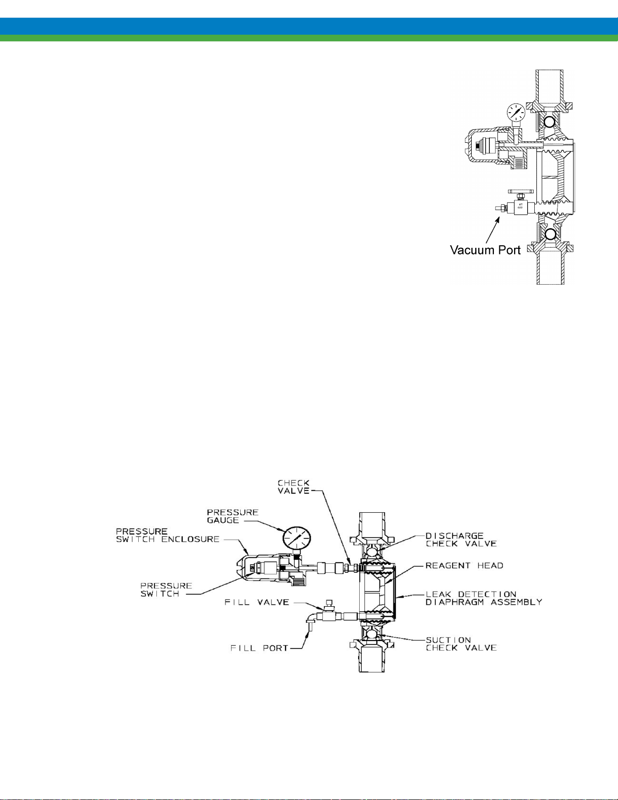
11.3 Leak Detection Option – Setup for Vacuum
A vacuum must be maintained at all times during pump operation,
otherwise, the diaphragm halves may separate during the suction stroke of
the pump, reducing flow capacity and potentially damaging the diaphragm.
Pumps incorporating the leak detection option are shipped from the factory
with the system evacuated to the operating vacuum of 650 mm Hg (26 in.
Hg). Due to flexure of the TFE diaphragms during transit and storage, the
initial vacuum may not be present at startup. When this occurs, re-evacuate
the system to the operating vacuum of 650 mm Hg (26 in. Hg).
1. Apply power to the alarm circuit.
2. Connect a vacuum pump capable of generating 26 inches of vacuum to
the Vacuum port, open the needle valve, and evacuate the system. A
hand-operated vacuum pump is generally appropriate for this procedure.
3. If required, verify system operation.
11.4 Leak Detection Option – Setup for Pressure
Figure 25
Pumps incorporating pressure leak detection are shipped from the factory with the system fully set up to
work at full pump pressure. No further setup is required. The standard factory barrier fluid is silicone
oil, if any other customer-specified media is used it must be compatible with construction materials.
The system will require proper setup after maintenance or repairs, see section 11.5 on the following
page for the proper procedure.
Figure 26
34
Page 41
11.5 Pressure System Set-up and Priming
If the pressurized leak detection system is opened to the atmosphere during maintenance or
inspection, the system must be re-primed properly to avoid diaphragm damage and ensure
proper leak detection operation and system performance.
The standard factory intermediate fluid is a Silicone oil. If any other customer-specified media
is used, it must be compatible with the materials of construction. Refer to the fluid
manufacturer’s literature for appropriate safety precautions.
Use the following procedure to set-up the pressurized leak-detection system:
1. Complete re-assembly of the diaphragm, reagent head, and external components. Ensure that
reagent head and tie-bar bolts are tightened according to the appropriate torque specifications
(consult Appendix IV)
2. Remove the pressure gauge from the housing body and replace with the straight tubing connection
supplied with the pump or conversion kit. Connect a vacuum supply (hand vacuum pump) to the tube
fitting.
If the system was previously sealed, you may need to remove the plug and re-install the hose
fittings at the fill port. There should be a container in the vacuum line to trap excess barrier
fluid. An inexpensive automotive brake bleeding kit is appropriate for this purpose.
3. Connect the fill tube, supplied with the replacement diaphragm, to the fill valve tubing connection.
Any short length of the appropriate sized tubing may be used for this purpose.
4. Open the fill valve.
5. Place the fill tube into a container of the barrier fluid being used.
6. Apply vacuum, the fluid should rise into the fill tube and enter the system.
7. Observe the fluid at the exit (vacuum pump) side. When clear, air free fluid is observed, close the fill
valve, while maintaining the vacuum on the system to begin the process of drawing out excess fluid.
If you a re-using a previous diaphragm, it will take time for the silicone fluid to migrate through
the system, be patient!
8. Release the vacuum, and remove both the fill tube and the vacuum pump from the fittings.
Continues next page…
35
Page 42

9. Empty the fill tube of fluid, and place it on the fitting near the switch, extending upwards, open to the
atmosphere.
10. Ensure that the eccentric box of the pump has been filled to the appropriate level with the correct
(normally Pulsalube 7H
™
) hydraulic fluid.
11. Adjust the pump to the zero stroke (0%) position.
12. If the pump is not already hydraulically primed, remove the PTP valve from the top of the pump
head. Using a plastic funnel or similar, slowly pour hydraulic fluid into the pump head cavity until
full.
13. Inspect the PTP valve to ensure the sealing o-ring is still in position, and re-insta l l the v alve.
14. Adjust the pump to full (100%) stroke.
15. In order to fully balance and evacuate the leak detection system, the pump must now run at normal
discharge pressure for a period of one hour. This ensures that excess barrier fluid is fully evacuated
from the system.
16. Supply either process fluid, or test fluid (i.e. water) to the suction fitting and ensure that the discharge
system is configured for safe operation. The pump can be started with minimal discharge pressure
and then slowly brought up to full pressure, if the system allows for this.
17. Apply power and start the pump. Hold down the PTP valve momentarily and observe the middle port
under the diagnostic cover. If no fluid is coming from this port, stop the pump and return to step 11.
If fluid is present, continue to step 18.
18. Slowly increase the discharge pressure to full operating pressure, and continue to run the pump for a
period of one hour.
19. During this time, excess barrier fluid will be displaced from the system into the short length of tubing
attached to the exit port, balancing the system for proper operation. A small pen mark on the tube can
assist in observing this process visually.
20. After the one-hour startup period, remove the tubing and connection from the housing body and
reinstall the pressure gage. Remove the fitting from the fill port and replace with the supplied pipe
plug.
21. Reconnect the alarm switch to the external system if necessary.
22. The pump and pressure leak-detection system are now properly prepared and ready for normal
service. During normal operation, the gauge should indicate 0 (zero) pressure.
Under certain circumstances, the system may not completely evacuate excess barrier fluid during
the procedure as outlined above. In these cases, after several days run time, a small amount of
pressure may build in the system. If this occurs, simply loo sen th e pressu re gau ge from the swi tch
housing and relieve a small amount of barrier fluid, returning the system to a zero-pressure state.
Once this startup procedure is completed, the pressure leak detection system should require no
further maintenance.
36
Page 43

11.6 Leak Detection System Maintenance
Although the PULSAlarm leak detection system requires minimal maintenance, vacuum must be
maintained to prevent false alarms and diaphragm damage.
11.6.1 Vacuum Setpoint Adjustment
If the optional switch is purchased, it is factory preset at the specified vacuum setpoint, 150 mm Hg (6
in. Hg), at which loss of vacuum causes the vacuum switch to actuate. The standard pressur e swi tch is
set to actuate at 5 psig.
Use the following procedure to perform a Vacuum setpoint adjustment:
1. Disconnect the alarm circuit from the vacuum switch.
2. Remove the switch enclosure cover and loosen the knurled locking ring on the switch.
3. Rotate the hex adjusting ring counterclockwise to increase or clockwise to decrease the setpoint.
4. Verify the new setpoint (refer to the next section).
5. Repeat steps (3) and (4) above until the required setpo int as attain ed.
6. Tighten the switch locking ring and replace the switch enclosure cover.
7. Reconnect the alarm circuit to the vacuum switch.
Use the following procedure to perform a setpoint adjustment test
1. Evacuate the system to approximately 650 mm Hg (26 in. Hg) OR properly prime and prepare the
pressure system.
2. Remove the switch cover and connect ohmmeter leads across the common terminal and the other
terminal used in operation (NO or NC).
3. Record the status of the switch (open or closed).
4.
a. Vacuum: Break the vacuum system at any point external to the pump to permit gradual loss of
vacuum.
b. Pressure
amount of pressure in the system.
5. Observe the ohmmeter to detect actuation.
: remove the pressure gauge, and install a hand pump or other means of producing a small
The setpoint can be observed by reading the vacuum/pressure
gauge upon actuation.
37
Page 44
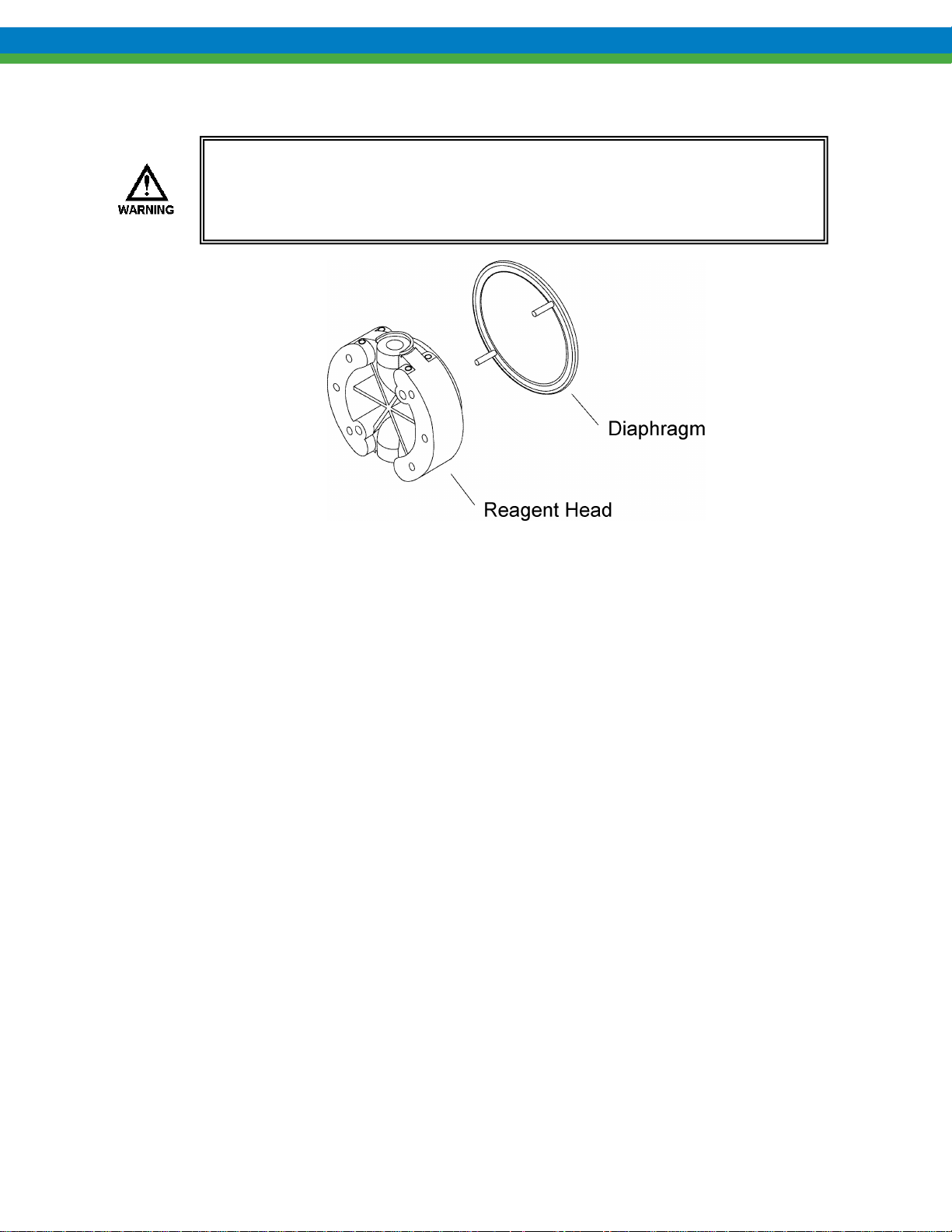
11.7 PULSAlarm Leak Detection Diaphragm Maintenance
After diaphragm failure, pressurized process fluid can be present in any
part of the PULSAlarm leak detection vacuum system. Take appropriate
precautions and handle with care.
Figure 27
11.7.1 Leak Detec ti on Dia phragm Removal
Use the following procedure to remove the Leak Detection Diaphragm:
1. Disconnect the power source to the drive motor.
2. Relieve all pressure from the piping system, and close the inlet and outlet shutoff valves
3. Take all precautions to prevent environmental and personnel exposure to hazardous materials.
4. Place a suitable container underneath the pump head to catch any liquid leakage.
5. Disconnect process piping and drain any process liquid, following material safety precautions.
6. Remove all but one top reagent head bolt. Oil will leak out between the pump head and reagent head
as the bolts are loosened.
7. Tilt the head and pour out any liquids retained by the check valves into a suitable container,
continuing to follow safety precautions as appropriate.
8. Remove the alarm switch assembly or pressure gauge from the reagent head.
9. Remove the bleed valve assembly and fla t gask et from the reagent head.
10. Rinse or clean the reagent head with an appropriate material.
11. Remove the diaphragm by running a blunt blade along the periphery and prying it out.
38
Page 45

11.7.2 Inspection
Remove and inspect the diaphragm assembly. It may have taken a permanent convex/concave set as
a result of normal flexure and conformance to the dish-plate. This condition is normal and is not
cause for replacement. The diaphragm must be replaced if it is deformed, dimpled, or obviously
damaged.
If the diaphragms have been removed from the spacer ring, the entire assembly should be replaced
to ensure proper sealing of its components.
11.7.3 Leak Detec ti on Dia phragm Reinstallation
1. Ensure that the critical sealing areas of diaphragm assembly, reagent head, and pump head are clean
and free from debris. Align the diaphragm assembly capillary tubes with mating holes in the seal
groove in the reagent head and position it in place against the reagent head. Ensure seating of the
diaphragm sealing ring into the mating groove in the reagent head.
2. Install the reagent head bolts and tighten in an alternating pattern to ensure an even seating force.
Torque to the values recommended in Appendix IV.
3. Apply sealing compound to the gauge/pressure switch assembly and reinstall to the upper port on the
reagent head.
4. Apply sealing compound to the fill valve assembly and reinstall to the lower port on the reagent head.
5. Open the needle valve
6. Connect a hand-held vacuum pump or other vacuum source to the vacuum port, which fits 6 mm (1/4
in.) I.D. tubing.
7. For a vacuum system, evacuate to approximately 650 mm Hg (26 in. Hg) and securely tighten
the needle valve after evacuation. Diaphragm damage or decreased flow will occur if a vacuum is
not drawn before the pump is returned to service. Refer to section 11.1 “Setup for Vacuum”.
8. Re-prime the pump head hydraulic system, see Section 7.2.2 on page 18
9. For a pressure system, see section 11.5, “Pressure System Set-up and Priming”
10. If required, test vacuum or pressure system operation.
11. After diaphragm set-up and priming, the pump is ready to be returned to service.
11.8 Leak Detection system conversion
Leak detection system conversion information can be found in Bulletin CV-LD-0203 (vacuum to pressure
system). For further conversion information and kits, please contact your loc al Pulsa fee der sa les rep res entat iv e.
39
Page 46

NPSHR
PULSAR
English (psi)
3
Metric (bar)
0.21
12. Appendix II Piping Calculations
Suction Head Requirements
All reciprocating metering pumps require a net positive suction head (NPSHR). Refer to Table 1 for the
(NPSHR) required for PULSAR pump models. The NPSHR is defined as the pressure required above
the absolute vapor pressure of the process fluid at the pumping temperature. This pressure is required at
the suction port of the pump throughout the entire pump stroking cycle in order to prevent cavitation of
the process fluid within the reagent head. The NPSHR is one of the requi rements necessary to assure
metering accuracy.
Table 1. NPSH
The net positive suction head available (NPSH
given system is calculated as follows for comparison to the NPSH
Equation 1. – For fluid viscosity below 50 centipoise.
Equation 2. – For fluid viscosity above 50 centipoise.
values
R
) must be greater than the NPSHR. The NPSHA of any
A
as shown in Table 1.
R
The variables used in the previous Equations must be in the units shown in Table 2 for the constants
listed to be used correctly.
40
Page 47

Units Set
English
Metric
NPSH
psi
bar
P
psia A
bar(a)
P
psi H
bar
P
psia V
bar(a)
L
feet S
meters
R
strokes/min
strokes/min
G
no units
no units
Q
gallons/hr
liters/hr
d
inches
millimeters
µ
centipoise
centipoise
L
feet D
Meters
P
psi T
bar
P
psi P
bar
V
feet/sec P
meters/sec
C
24,600 1
640
C
45,700 2
1.84
C
46.8 3
0.91
MSH
PULSAR
PULSAR*
English, (psia)
5
7.5
Metric, (bar(a))
0.35
0.53
Table 2. Unit sets and constant values for use in NPSH Equations.
Variable
If piping sizes vary throughout the suction line, different additive values may be used for the
pressure losses attributed to the liquid’s acceleration and deceleration. Use the last term of
Equation 1 or 2 as many times as needed in the equation to adjust for different lengths of different
pipe diameters in the suction line. (Everything but the pipe length and diameter will stay the same
in the equation.)
All reciprocating metering pumps also require that a minimum absolute pressure and minimum suction
head (MSH), be maintained at the pump inlet throughout the pumping cycle to ensure a stable hydraulic
system and proper pump operation. The sum of the NPSH
and the vapor pressure (P
A
) must be greater
V
than the values shown in Table 3.
Table 3. Minimum values for the sum of NPSH
and vapor pressure. (MSH)
A
* PULSAR Pump with PULSAlarm leak detection diaphragm.
41
Page 48
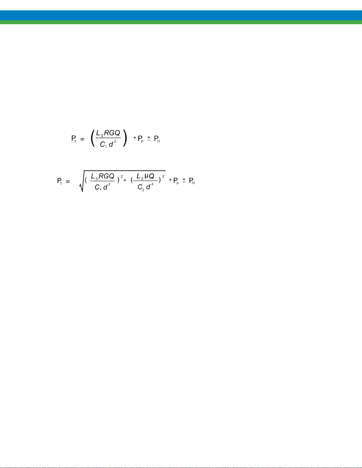
NPSH
=
R
Net positive suction head required, [psi, bar]
NPSH
=
Net positive suction head available, [psi, bar]
P
= A
Pressure at the surface of the liquid being pumped (atmospheric or supply tank
P
= H
Head pressure above (+) or below (-) the pump centerline, [psi, bar,] (convert from
ft or m)
P
= V
Absolute vapor pressure at pumping temperature of the process liquid at pump inlet,
[psi(a), bar(a)]
L
= S
Length of suction piping (actual, not equivalent), [ft, m]
R = Pump stroking rate, strokes/min [spm]
G = Specific gravity of process liquid, [no units]
Q = Pump average flow rate, [gph, lph]
d = Internal pipe diameter, [inches, mm]
C1, C2, C3
=
Numeric constants used in Equations 1 - 4 [no units]
µ = Viscosity of process liquid at pumping temperature, centipoise [cp]
L
= D
Length of discharge piping (actual, not equivalent), [ft, m]
P
= P
System discharge pressure, [psi(g), bar(g)]
P
= T
Peak pump discharge pressure at the discharge port, [psi(g), bar(g)]
V
= P
Peak liquid velocity generated by the pump, (suction or discharge) [ft/s, m/s]
System Back Pressure
The system backpressure must exceed the suction pressure by at least 5 psi (0.35 bar) in order to prevent
flow through, however it must not exceed the rated discharge pressure of the pump. Flow through can
be defined as the process liquid flowing from a higher pressure to a lower pressure (downhill pumping),
which attributes to pump failure and undesired flow at pump shutdown. If the system backpressure is
not at least 5 psi (0.35 bar) greater than the suction pressure, a backpressure valve must be installed in
the discharge piping. To calculate the system’s total backpressure use Equation 3 or 4.
Equation 3. – For fluid viscosity below 50 centipoise.
Equation 4. – For fluid viscosity above 50 centipoise.
Nomenclature
A
blanket pressure) [psi(a), bar(a)]
42
Page 49

13. Appendix III Oil Specifications
PULSAlube # 7H
API Gravity (ASTM D 287) = 31
Viscosity (ASTM D 2161) SSU @ 100° F = 175
Viscosity (ASTM D 2161) SSU @ 210° F = 51
Viscosity Index (ASTM D 2270) = 193
Pour Point (ASTM D 97) Degrees F (C) = -60(-51)
Flash Point, COC (ASTM D 92) Degrees F (C) = 367(186)
Fire Point, COC (ASTM D 92) Degrees F (C) = 403(205)
Color = purple
PULSAlube # 8G
AGMA Number = 7 EP
ISO Viscosity Grade = 460
API Gravity (ASTM D 287) = 34.1
Viscosity (ASTM D 2161) SSU @ 100° F = 2241
Viscosity (ASTM D 2161) SSU @ 210° F = 225
Viscosity Index (ASTM D 2270) = 167
Pour Point (ASTM D 97) Degrees F (C) = -40(-40)
Flash Point, COC (ASTM D 92) Degrees F (C) = 490(254)
Timken OK Load (ASTM D 2782) Lb(kg) = 100+(45+)
Four Ball EP Test (ASTM D 2783)
Weld Point kg = 250
Load Wear Index = 47
Rust Test (ASTM D 665A&B) = Pass
Oxidation Test (ASTM D 2893) = Pass
Demulsibility Test (ASTM D 2711) = Pass
Foam Test (ASTM D 892) = Pass
Copper Corrosion (ASTM D 130) = 1-A
Color = amber
43
Page 50
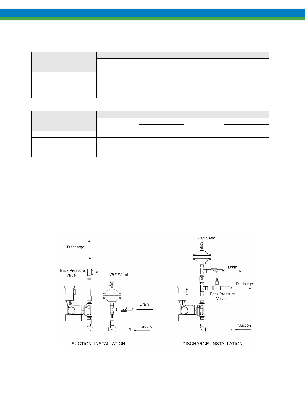
Head Bolts
Tie bar Bolts
No. Bolts &
Size
Torque
No. Bolts &
Size
Torque
N-m
Ft–lbs.
N-m
Ft–lbs.
NP160001
A
(6) M10 * 1.5
39
29
(4) M8 * 1.25
8
6
NP160002
B
(6) M12 * 1.75
68
50
(4) M8 * 1.25
8
6
NP160003
C
(6) M10 * 1.5
39
29
(4) M8 * 1.25
8
6
NP160004
D
(6) M8 * 1.25
20
15
(4) M8 * 1.25
8
6
Head Bolts
Tie bar Bolts
No. Bolts &
Size
Torque
No. Bolts &
Size
Torque
N-cm
In–lbs.
N-cm
In-lbs.
NP160012
A
(6) M10 * 1.5
850
75
(4) M8 * 1.25
250
22
NP160014
B
(6) M12 * 1.75
850
75
(4) M8 * 1.25
250
22
NP160011
C
(6) M10 * 1.5
850
75
(4) M8 * 1.25
250
22
NP160013
D
(6) M8 * 1.25
850
75
(4) M8 * 1.25
250
22
14. Appendix IV Bolt Torque Recommendations
Metal Construction
Reagent Head
Part No.
Head
Size
Plastic Construction
Reagent Head
Part No.
Please note that torque values for plastic heads are given in N-centimeters and inch-lbs
Head
Size
15. Appendix V Pulsafeeder Accessories
Pulsatrol Installation, Operation, & Removal Instructions
The PULSAtrol is a pneumatically charged diaphragm-type chamber that intermittently stores energy.
Used on the inlet, it will improve NPSHA (Net Positive Suction Head available) characteristics of the
suction piping system. On the discharge line it will reduce peak pressures and pulsating flow variations.
Figure 28
44
Page 51

Installation
On both discharge and suction lines, it is desirable to mount the PULSAtrol as close to the pump
connection as possible. It can be mounted in any position: horizontally, vertically, or at any angle. A
shutoff valve should always be used between the piping system and PULSAtrol. If the discharge line is
open to atmospheric pressure, a backpressure valve should also be incorporated in the system near the
PULSAtrol to assure proper operation. Pulsation dampeners do require regular maintenance and
inspection. Charge pressure should be checked every 2-4 months and renewed as needed. Temperature,
pressure, and other variables will affect charge life and diaphragm/bladder life.
A) Discharge Setup
The PULSAtrol may be precharged with air or nitrogen. When properly precharged the diaphragm is
positioned against the bottom liquid chamber. It is therefore necessary to drain all liquid below the
diaphragm and vent to atmospheric pressure when precharging.
Use the precharge pressure as determined from the PULSAtrol selection and sizing procedure (Catalog
No. 211). This can vary from 50 to 80% of mean line pressure in accordance with fluctuation level
selected. The PULSAtrol is now ready for service and the diaphragm will move to a neutral position as
liquid enters the chamber.
Use the following to complete a Pre Charge Procedure for Discharge Installation
1. Calculate the precharge pressure
a) Mean Line Pressure (PSIG)
b) Absolute Pressure (PSIA)
c) Pressure Absolute
2. Isolate PULSAtrol from line.
3. Carefully drain off process fluid by opening a drain valve (see recommend piping arrangement).
4. Apply precharge pressure (additional liquid may drain as diaphragm moves).
5. Close drain valve.
6. Place PULSAtrol in stream.
– Atmospheric Pressure = Precharge Pressure (PSIG)
+ Atmospheric Pressure = Absolute Pressure (PSIA)
x Precharge Percentage (80% max) = Pressure Absolute
B) Suction Setup (Flooded Suction)
Charge the PULSAtrol with adequate pressure to overcome the static suction head. Start up the pump.
Depress the stem on the charge valve, but only during discharge strokes of the pump, until the gauge
indicates pressure pulses. The diaphragm has now centered allowing the PULSAtrol to accumulate
liquid while the pump is discharging. If too much air becomes released and the gauge will not indicate
pressure pulses, recharge the PULSAtrol and repeat the procedure.
Use the following to complete a Pre Charge Procedure for Suction Installation
1. Isolate accumulator from line.
2. Carefully drain off process fluid by opening a drain valve (refer to Figure 24).
3. Apply 5-10 psi precharge pressure (additional liquid may drain as diaphragm moves).
4. Close drain valve.
5. Bleed off all pressure on the PULSAtrol.
6. Open the valve to put PULSAtrol in stream.
7. Push in on the stem of the charging valve during the discharge stroke of the pump and release during
the suction stroke.
8. Continue this for about 10 times and observe the compound gauge. As accumulator functions, the
needle will go from pressure to vacuum.
45
Page 52

PULSAtrol Removal
When removing or disassembling a PULSAtrol, drain all piping and remove all air and process pressure.
Assume that the diaphragm is broken and the chamber is flooded under pressure since the pressure
gauge could be damaged. Separate chambers with caution in a direction away from the body.
Back Pressure Valve
The Pulsafeeder diaphragm backpressure valve creates constant backpressure. A TFE diaphragm,
offering maximum chemical protection and service life, seals spring and bonnet from product. This
diaphragm seals directly on a replaceable seat.
Be sure to install with fluid flow in direction of arrow on valve body. If arrow is missing from plastic
valve body, install with flow exiting out center hole of valve body.
Pressure Relief Valve
Pressure relief valves should be utilized in any system to protect the pump and other process equipment
and piping from potentially damaging or unsafe pressures. It is critical that the pressure relief valve be
mounted in the discharge piping system before any other devices that can potentially block or impede
flow, or it cannot perform its intended function (refer to Figure 8).
The pressure relief valve must be set to a pressure high enough to prevent unwanted fluid relief during
normal process conditions. A setting that is approximately 10-20% above normal operating pressures is
generally sufficient. The valve must also be set below the maximum pressure capability of the lowest
rated device in the system. For example, if a PULSAR pump is rated with a maximum pressure
capability of 150 psi (approx. 10 bar) but the piping within the system is rated only to a maximum of
100 psi (approx. 7 bar) then the pressure relief valve must be set to a value lower than 100 psi.
Figure 29
46
Page 53

47
Page 54

12 - 2006
Bulletin PR-IOM-0802
Rev D
 Loading...