

Page 1
i
INSTALLATION
BULLETIN No. 418
OPERATION
MAINTENANCE
INSTRUCTION
Page 2

ii
PULSA SERIES GUARANTEE
Should you experience a problem with your Pulsafeeder pump, first consult the troubleshooting guide
in your operation and maintenance manual. If the problem is not covered or cannot be solved, please
contact your local Pulsafeeder Sales Representative, or our Technical Services Department for further
assistance.
Trained technicians are available to diagnose your problem and arrange a solution. Solutions may
include purchase of replacement parts or returning the unit to the factory for inspection and repair.
All returns require a Return Authorization number to be issued by Pulsafeeder. Parts purchased to
correct a warranty issue may be credited after an examination of original parts by Pulsafeeder.
Warranty parts returned as defective which test good will be sent back freight collect. No credit will
be issued on any replacement electronic parts.
Any modifications or out-of-warranty repairs will be subject to bench fees and costs asso ci ated with
replacement parts.
In addition, Pulsafeeder guarantees its PULSA Series drive assemblies for a period of two years from
the date of shipment. All other material and workmanship are fully covered for a period of one year.
Any parts found to be defective within the above time span will be replaced free of charge, F.O.B.
factory.
Equipment or accessories manufactured by others but purchased through Pulsafeeder, such as electric
motors, are guaranteed only to the extent of the original manufacturer.
Damages incurred from misuse, abuse, and/or improper protection during storage will be cause to
void the guarantee. Erosion, corrosion, or improper application of the equipment or related piping by
the buyer or any third party is also excluded from the guarantee.
The above guarantee is in lieu of any other guarantee, either expressed or implied. We make no
warranty of fitness or merchantability. No agent of ours is authorized to make any warranty other
than the above.
Safety Considerations:
1. Read and understand all related instructions and documentation before attempting to install or
maintain this eq uip ment
2. Observe all special instructions, notes, and cautions.
3. Act with care and exercise good common sense and judgment during all installation, adjustment, and
maintenance procedures.
4. Ensure that all safety and work procedures and standards that are applicable to your company and
facility are followed during the installation, maintenance, and operation of this equipment.
Information in this document is subject to change without notice. No part of this publication may be
reproduced, stored in a retrieval system or transmitted in any form or any means electronic or mechanical,
including photocopying and recording for any purpose other than the purchaser’s personal use without the
written permission of Pulsafeeder, Inc.
Page 3

iii
Conventions
A
Tips have been included within this bulletin to help the operator run the
Table of Contents
1. INTRODUCTION ........................................................................................................................................ 1
1.1 General Description ................................................................................................................ 1
1.2 Options ..................................................................................................................................... 3
Input Signals ............................................................................................................................ 3
1.3
Control Modes ......................................................................................................................... 4
1.4
Current Output Signals ........................................................................................................... 4
1.5
2. EQUIPMENT INSPECTION ....................................................................................................................... 5
3. PROCEDURAL NOTES ............................................................................................................................ 5
4. INSTALLATION ...................................................................................................................................... 6
4.1 Wiring Up .................................................................................................................................. 6
4.2 Start Up ..................................................................................................................................... 6
CALIBRATION ....................................................................................................................................... 7
5.
5.1 Deadband Adjustment ............................................................................................................ 7
5.2 Circuit Board Calibration ........................................................................................................ 7
Meter Readout (current Output) Calib ration ......................................................................... 9
5.3
5.4 Auto-Manual Calibration ......................................................................................................... 10
6. REPAIRS ........................................................................................................................................... 11
6.1 Limit Switch Adjustment......................................................................................................... 11
6.2 Potentiometer .......................................................................................................................... 11
6.3 Zero Alignment ........................................................................................................................ 12
6.4 Brake Air Gap ........................................................................................................................... 13
6.5 Jammed Slider Block .............................................................................................................. 14
7. ORDERING PARTS ................................................................................................................................. 15
8. CONVERSION (MANUAL TO PULSAMATIC) .............................................................................................. 15
9. TROUBLESHOOTING CHART................................................................................................................... 16
For the remainder of this bulletin, the following Conventions are in effect.
WARNING DEFINES A CONDITION THAT COULD CAUSE DAMAGE TO BOTH
THE EQUIPMENT AND THE PERSONNEL OPERATING IT
ATTENTION TO ANY WARNING
.
Notes are general information meant to make operating the equipment easier.
equipment in the most efficient manner possible. These “Tips” are drawn from
the knowledge and experience of our staff engineers, and input from the field.
. PAY CLOSE
Page 4

1. Introduction
1.1 General Description
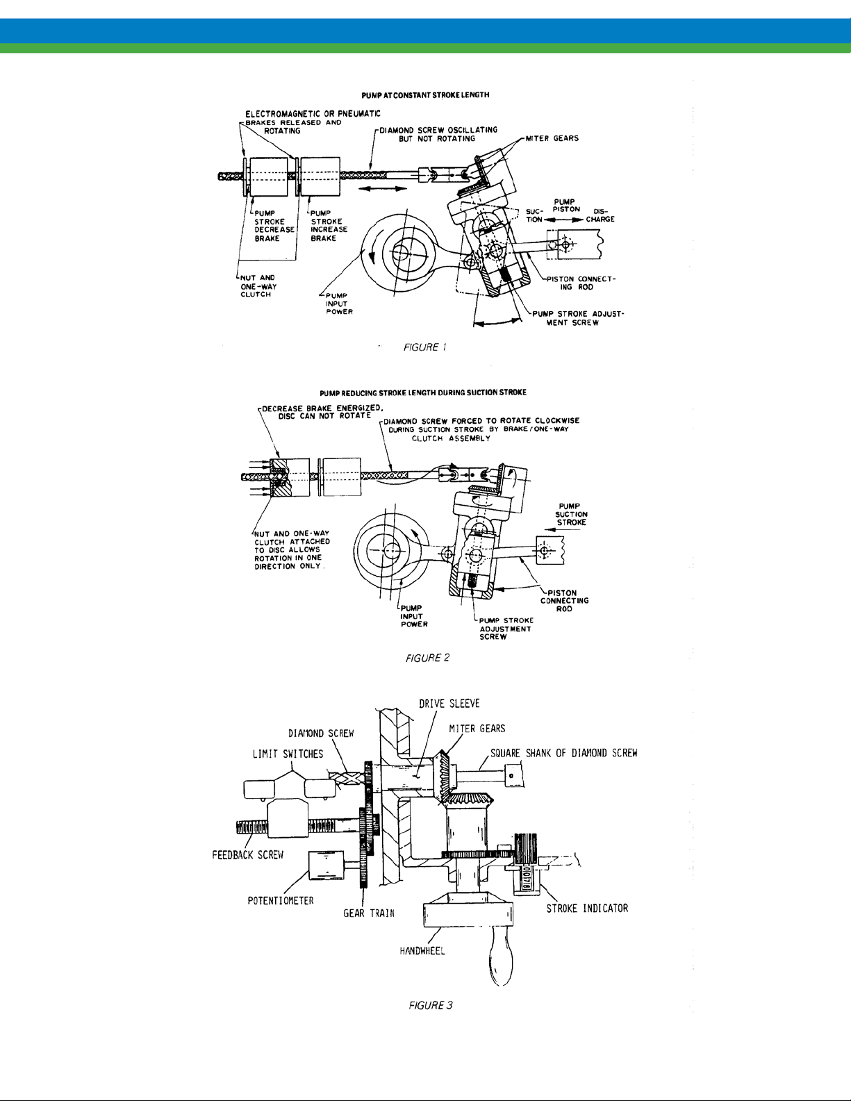
The PULSAmatic actuator converts reciprocating motion of the pump into rotary motion to turn
the pump’s stroke adjustment screw. By selectively engaging either of the two oppositely oriented,
one-way clutches, one of two corresponding nuts hat ordinarily rotate freely on a “diamond”
actuator shaft is blocked form rotation when the shaft moves longitudinally in one direction. Thus
locked, the nut compels the shaft to rotate, thereby turning the adjustment screw to which it is
connected.
The actuator assembly consists of the following major components: the actuator shaft (a major
portion of which is in the form of a diamond screw), tow brake housings, two one-way clutches,
and two helix nuts. Mounted side-by-side, the two brake housings are concentric to the axis of the
actuator shaft. The helix nuts are located between the inner walls of the brake housings and the
surface of the shaft. One nut engages the right-hand thread of the shaft and other engages the lefthand thread. Each nut rotates within a one-way clutch.
In operation, the actuator shaft reciprocates along its axis. When the brakes are de-energized, each
nut, along with its respective clutch, is free to rotate in alternation clockwise and counterclockwise
directions as it is driven by grooves in the shaft. Under this condition, the shaft and adjustment
screw do not rotate.
Upon energizing one of the brakes, the corresponding one-way clutch is utilized allowing the nut
to rotate only in one direction, while the shaft is moving longitudinally during the e discharge
stroke of the pump (linear motion of the shaft is now in the opposite direction), the clutch prevents
the nut from rotating, causing the shaft to rotate. This rotation is transmitted by a mechanism
inside the gearbox housing to the pump ad justment screw so that the piston stroke length is
changed. By energizing the other brake, the adjustment screw is rotated in the opposite direction.
To increase or decrease pump output, it is only necessary to selectively energize either brake.
Rotary motion of the actuator shaft also rotates a sleeve which in turn drives a gear train through a
spur gear pressed on one end of the sleeve. The gear train transfers outputs for a positional
feedback potentiometer and limit switches. A bevel gear mounted on the opposite side of the drive
sleeve is meshed with a hand wheel bevel gear and mechanical stroke position indicator.
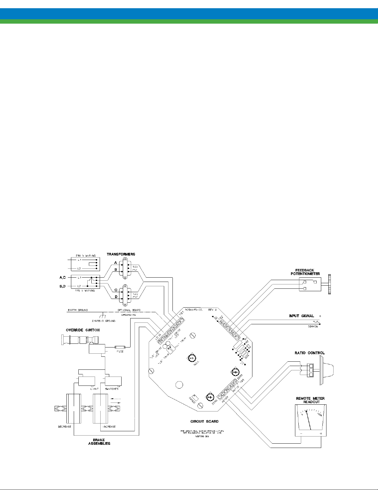
A printed circuit board contains standard and optional control circuits. The incoming command
signal is compared with the internal feedback signal. If the two are equal or nearly so, no action
occurs. If the command signal is greater, one brake is energized, resulting in a corresponding
change in pump output (stroke length) and feedback signal. If the feedback signal is greater than
the command signal, the other brake is energized, changing the pump output and feedback signal
in the reverse direction. When the feedback signal matches the command signal, stroke length is
properly positioned and adjustment is halted.
The override switch, operable from outside the actuator assembly, disconnects the brakes from the
circuit board to permit manual adjustment using the hand wheel. The “out” position is for manual
operation and the “in” position is for automatic operation.
Page 5
2
Page 6
3
1.2 Options
The PULSAmatic actuator is configured at the factory for a variety of options, both singly and in
various combinations. The appropriate wiring diagrams external to the circuit board are included
with each pump shipment.
1.3 Input Signals
.
Standard signals are:
1-5 mA DC @ 2000 ohm Impedance
4-20 mA DC @ 470 ohm Impedance
10-50 mA DC @ 180 ohm Impedance
0-10 V DC @ Greater than 270,000 ohm Impedance
Slide wire (Remote, 1000-ohm manual control potentiometer, user-supplied).
Actions
Direct Acting- minimum and maximum input signal levels correspond directly to minimum and
maximum stroke settings respectively. For example, a 4-20 mA signal ranges stroke from zero at
4mA to full at 20 mA. This is the standard mode of action.
Reverse Acting- Signal response is inverted relative to direct acting. For example, a 4-20 mA
signal ranges stroke from full at 4 mA to zero at 20 mA. This is an optional mode of action.
Page 7

4
1.4 Control Modes
Ratio Control- When ratio control is applied, the range of stroke adjustment is proportionally
reduced to a level equal to the ratio setting. For example, at a ratio setting of 60%, the full span of
the input signal commands the pump to operate between zero and 60% of full stroke rather than
over the full range of the stroke. The ratio is manually set between zero and 100% using a remote
potentiometer.
Split Ranging- A single control signal command s two pumps, each pump responding only to a
portion of the total range of the signal. The PULSAmatic controller opera tes spec ifica lly as
follows: One pump is commanded from zero to full stroke over the lower half of the input signal,
and a second pump is commanded, in the reverse-acting mode, from full to zero stroke over the
higher half of the input signal. For example, a 4-20 mA input signal controls the first pump
between zero stroke at 4mA to full stroke at 12 mA and controls the second pump between full
stroke at 12 mA and zero stroke at 20 mA
Manual- Remote manual stroke adjustment potentiometer.
Auto-Manual- Remote switch selection between automatic and remote manual operation.
1.5 Current Output Signals
0-10 mA DC – 500 ohm Impedance max.
4-20 mA DC – 250 ohm Impedance max.
Page 8

5
2. Equipment Inspection
1. Check all equipment for completeness against the order and for shipping damage. Shortages or
damage should be reported immediately to your PULSA Series representative.
2. Check pump and PULSAmatic stroke control identification tags for serial and model numbers.
There are two tags: one on the pump gearbox which includes the pump model number and
another on the PULSAmatic enclosure. The pump gearbox serial number identifies the
PULSAmatic actuator as well as any separately mounted control stations. Each should
correspond to the information on the parts lists. Use these reference numbers whenever
corresponding with the factory.
3. Check the envelope containing this bulletin for service parts list and special drawings and
wiring diagrams for specified control options.
3. Procedural Notes
Electrical repairs and calibrations should be undertaken only by an electronic technician q2ualified
in the maintenance and repair of linear (an alog) indust rial process control equipm ent.
A digital voltmeter and a process control signal generator are required for electronic calibrations.
Troubleshooting and repair may require access to the mechanism linking the actuator control to the
oscillating housing inside the pump gearbox. This requires removal and replacement of the rear
gearbox cover assembly. Refer to the pump operations manual for the description of these
operations.
Detailed circuit board schematics, containing component identifications, are available from the
factory to facilitate electronic circuit troubleshooting and repair at the board level.
The following conventions and procedures apply throughout this bulletin.
1. “Zero Stroke” refers to a zero, or (000) setting on the mechanical stroke counter.
“Full Stroke” refers to a full or (100) setting on the mechanical stroke counter.
2. A “low end” input control s ig na l is on e th at co m mands the pump to zero stroke
A “high end” input control signal is one that commands the pump to full stroke.
Note that the signal values are inverted in the reverse acting option so that, for example, a 4-20
mA signal commands full to zero stroke. In this case, 4 mA is the high end signal. See
“Options” under “principals of Operation” above for signal definitions.
3. Pump stroke can be manually or automatically set as required for calibrations and adjustments.
References to the disable switch (“out” for manual, “in” for automatic) may be omitted.
Manual, or hand wheel adjustments made while the pump is not operating, require that
pressures be relieved from both the suction and discharge lines.
4. Wiring terminals are indentified on the circuit board and referred to directly. For example
TB2-3 refers to terminal No. 3 on Terminal Board No. 2, (reference Figure 4).
CAUTION: When troubleshooting, always remove signal potential prior to
disconnecting AC power. This will help protect integrated circuits on the circuit
board.
Page 9

6
4. INSTALLATION
4.1 Wiring Up
(Refer to any special wiring diagrams and installation drawings supplied by Pulsafeeder).
AC power lines should be routed to the actuator via a separate conduit from the control signal and
any optional accessory wiring. A separate switched an d protec ted ci rcu it is recommended for the
actuator power supply.
Remove the PULSAmatic actuator cover, which is secured by two screws, or screwed on, in the
case of an explosion proof enclosure. The two power transformers should be wired as described by
wiring diagrams. Power and ground wire should be No. 18 AWG wire size or larger. A power
ground screw is provided on the backing plate near the conduit openings. Terminal TB1-4 is also
provided as an optional circuit board ground. This terminal is connected to the circuit board
ground through a 4700 ohm resistor.
Run the signal and accessory wiring using the alternative conduit opening. No. 22 AWG wire size
or larger is recommended. Make all connections per the diagram that apply to the combination of
signal and accessories provided.
Explosion proof actuators are Underwriters Laboratories (UL) listed and are labeled with the
hazardous environments for which they are rated, along with any special installation specifications
required in support of UL listing. They must be installed, wired, operated, and maintained in
accordance with local electrical codes.
CAUTION: T o help protect the integrated circuits in the servo amplifier, always
energize AC power prior to connecting the signal leads.
4.2 Start Up
Ever actuator is adjusted and calibrated at the factory. However, due to variations in input signals
RECALIBRATION IS REQUIRED. Prior to performing this procedure (as outlined in the next
section) it is recommended that the following steps be followed in order to verify proper
mechanical operation and limit switch adjustment.
Mechanical Operation- Before applying electrical power, remove the coupling guard between
pump and motor and manually rotate the motor shaft through several revolutions. The thin metal
brake armatures should rotate in alternate directions as the actuator shaft moves first in one
direction and then the other. (If they do not, the actuator linkage may be disconnected from the
oscillating housing under the main cover). Repla ce the motor coupling guard.
Limit Switch Verification- with the counter indicating 090 or less, pull out the handwheel and
rotate to increase the count. As a value of 200 is approached (from 099 to 100) a faint click should
be heard from one of the limit switches. If an audible indication of the limit switch operation
cannot be obtained, operation may be verified electrically. Turn the handwheel back to a counter
indication of 090 and pull out the override switch. Continuity should exist between the terminals
of the limit switch mounted on a double switch bracket, farthest from the printed circuit board.
Pull out and slowly rotate the handwheel so that the counter indication increases. The switch
should open, indicated by loss of continuity, when the stroke indicator reads between 097 and 100.
Page 10

7
Operation of the second limit switch (the one closest to the circuit board) may be checked in a
similar manner. The limit switch should be open at a stroke indicator reading between 001 and
000.
If either of the lim it sw it ch e s appears to be out of adjustment refer to “repairs- Limit Switch
Adjustment”.
Barring any problems proceed with “Calibrations and Adjustments”.
Refer also to the “Equipment Startup” section of the pump Installation, Operation, and
Maintenance Instructions.
5. Calibration
As stated previously, field recalibration is required upon startup. The following procures are to be
performed in sequence as presented. Refer to Figure 4 as required for circuit component locations.
5.1 Deadband Adju stme nt
With pump stroke positioned exactly as commanded by the input signal, a certain change in signal
must occur in either direction (increase or decrease) in order to cause the actuator to respond.
For example, if a pump is operating at 50% stroke in response to a 50% input signal, the signal
must typically increase to 51% or decrease to 49% before the actuator does not respond, or is
“dead”, is called “deadband”. If deadband is too narrow, the actuator will frequently make slight
adjustments in response o small signal variations. In the extreme case, the actuator will continually
“hunt” back and forth over a small range of adjustment. If deadband is too broad, response will lag
and accuracy will suffer. The “Null” potentiometer near the center of the circuit board adjusts
deadband. Clockwise movement decreases deadband, increasing sensitivity. Counterclockwise
movement increases deadband, decreasing sensitivity.
Deadband adjustment for response to a 1% change in signal (depicted in the example above) is
appropriate to most installations. This can be set approximately by setting the “Null”
potentiometer in the six o’clock position shown in Figure 4. To check deadband adjustment, cycle
the pump automatically, by input signal command, to an approximately midrange stroke setting.
Leaving the override switch in the “in” or automatic position, slowly adjust the handwheel in
either direction until the actuator responds to return the stroke to the original set point. Care must
be taken during this operation, as the handwheel will move without warning. Deadband is
observed on the mechanical stroke indicator as the difference between the original stroke setting
and that at which the actuat or responds.
5.2 Circuit Board Calibration
The PULSAmatic circuit senses all control signals in terms of voltage. A current signal is
converted to a voltage signal measured across a resistor, provided in the circuit board, through
which the current passes. For example, the most commons signal, 4-20 mA DC, passes through a
470 ohm resistor to generate a 1.88-9.40 volt DC signal, (0-6.3 v with Ratio Control).
This procedure trims the actuator circuits to the low and high ends of the actual input control
signal.
Page 11

8
Without Ratio Control – Coarse Adjustment
1. Place the override switch in the “out” or manual position. The pump need not be running for
coarse adjustment.
2. Set up a voltmeter to read a full scale DC voltage of 10.
3. Connect the positive lead of the voltmeter to TB2-2 and the negative lead to TB2-1.
4. Set the control signal at the low end (0%) and record the voltage.
5. Set the control signal at the high end (100%) and record the voltage.
6. Set up a voltmeter for DC voltage measurement between TB2-5 (positive) and TB2-1
(common).
7. Adjust the “LO” trim potentiometer on the circuit board to the voltage recorded in step 4.
8. Set up the voltmeter for DC voltage measurement between TB2-4 (positive) and TB201
(common).
9. Adjust the “HI” trim potentiometer on the circuit board to the voltage recorded in step 5.
10. The above adjustments are interactive. It may be necessary to repeat steps (2) thro ug h (5)
several times until the voltages stabilize. This completes coarse adjustment.
Without Ratio Control – Fine Adjustment
11. With the override switch still in the “out” or manual position start the pump.
12. Set up a voltmeter for DC voltage measurement between TB2-3 (positive) and TB2-1
(common).
13. Set the control signal at the low end (0%). Move the override switch to the “in” or auto
position. The LO” drive LED will light and the pump with automatically adjust to the 0%
stroke.
14. Adjust the “LO” trim potentiometer on the circuit board to the voltage recorded in step (4).
The stroke indicator should now read 000-001 and both LED drive lights should be off.
15. Apply a high end (100%) control signal. Allow the pump to adjust to 100% stroke.
16. With the voltmeter remaining as set up in step (12) above, adjust the “HI” trim potentiometer
to the voltage recorded in step (5). The stroke indicator should now read 099-100 and again
both drive lights should be off.
17. The above adjustments are interactive. It may be necessary to repeat steps (12) through (16)
several times until the voltages stabilize. This completes fine adjustment.
With Ratio Control (Optional Feature) – Coarse Adjustment
1. With the override switch in the “out” or manual position, start the pump.
2. Set the controls signal at the low end (0%). Move the override switch “in” to the auto position
and allow the pump to adjust to 0%.
3. Place the override switch back in the “out” or manual position. Check the stroke indicator; if it
does not read 000-001 use the handwheel to manually adjust it to this point.
4. Set the remote ratio control potentiometer at 100%.
5. Set up the voltmeter for DC voltage measurement between TB3-4 (positive) and TB3-6
(common).
Page 12

9
6. Adjust the “Ratio Zero” potentiometer on the circuit board (to the right of TB3) to +/- 0.0
volts.
7. With the voltmeter remaining as set up in step (5) above, set the control signal at the high end
(100%) and record the voltage.
8. Set up a voltmeter for CD voltage measurement between TB2-5 (positive) and TB2-1
(common).
9. Adjust the “LO” trim potentiometer on the circuit board to +/-0.0 volts.
10. Set up a voltmeter for DC voltage measurement between TB2-4 (positive) and TB2-1
(common).
11. Adjust the “HI” trim potentiometer on the circuit board to the high end voltage recorded in
setup (7) above.
12. The above adjustments are interactive. It may be necessary to repeat steps (8) through (12)
several times until the voltages stabilize. This completes coarse adjustment
With Ratio Control (Optional Feature) – Fine Adjustment
13. With the override switch still in the “out” or manual position start the pump.
14. Set up a voltmeter for DC voltage measurement between TB2-3 (positive) and TB2-1
(common).
15. Set the control signal at the low end (0%). Move the override switch to the “in” or auto
position. The “LO” drive LED will light and the pump will automatically adjust to 0% stroke.
16. Adjust the “LO” trim potentiometer on the circuit board to the voltage recorded in step (6).
The stroke indicator should now read 000-001 and both LED drive lights should be off.
17. Apply a high end (100%) control signal. Allow the pump to adjust to 100% stroke.
18. With the voltmeter remaining as set up in step (14) above, adjust the “HI” trim potentiometer
to the voltage recorded in step (7). The stroke indicator should now read 099-100 and again
both drive lights should be off.
19. The above adjustments are interactive. It may be necessary to repeat steps (12) through (16)
several times until the voltages stabilize. This completes fine adjustment.
5.3 Meter Readout Calibration
This procedure trims the current output to the calibrated range of pump capacity or stroke. Because
the output is based on position of the feedback potentiometer, an input signal is not required for
adjustment.
Depending on the options ordered an analog meter will have been supplied for signal indication. If
not, an amp meter will be required to measure the output, 0-10 mA standard, 4-20 mA optional.
1. With the pump set a zero stroke, adjust the “Meter Zero” potentiometer on the circuit board (to
the left of TB-3, as shown in Figure 4) for zero (0%) meter indication or 0% current level as
applicable. Note that with 4-20 mA output the “Meter Zero” and “Range” potentiometers will
be reversed.
2. Will the pump set at full stroke; adjust the “Range” potentiometer on the circuit board for
100% meter indication or 100% current level as applicable.
3. The above adjustments are interactive. Repeat steps (1) through (2) several times until the
meter accurately indicates both zero and full stroke settings.
Page 13

10
5.4 Auto-Manual Calibration
This procedure trims the manual control potentiometer to the low and high ends o the actual input
control signal.
The main circuit board must be calibrated prior to this procedure.
For current type control signals, a resistor is installed across terminals of the auto-manual switch.
If present, this resistor must remain in place.
This procedure can be performed with the pump on-line and operating, in the manual (handwheel)
control mode, with the override switch in the “out” position.
1. All voltages in this procedure are DC and are measured between TB2-2 (positive) and TB2-1
(common).
2. Set the remote auto-manual selector switch to the “Auto” position.
3. Set the control signal to the low end and record voltage.
4. Set the control signal to the high end and record voltage.
5. Set the remote selector switch to the “manual” position.
6. Set the remote “percent stroke” control potentiometer at zero percent.
7. Adjust the “LO” trim potentiometer on the small circuit board mounted on the back of the
“percent stroke’ potentiometer for the low end voltage recorded in step (3) above. Verify that
both LEDS on the main circuit board are off.
8. Set “percent stroke” potentiometer at 100%.
9. Adjust the “HI” trim potentiometer on the small circuit board on back of “percent stroke”
potentiometer for high end voltage recorded in step (4) above. Verify that both LEDS on main
circuit boards are off.
10. The above adjustments are interactive. It may be necessary to repeat steps 6 through 9 several
times, until the voltages stabilize.
Page 14

11
6. Repairs
6.1 Limit Switch Adjustment
This procedure adjust the limit switches to prevent the pump mechanism from jamming due to
over travel, without significantly restricting the range of stroke length settings.
The limit switches disable the actuator from operating below zero strokes or above full stroke,
either of which can cause jamming. For this reason, correct limit switch adjustment is very
important.
The procedure for checking limit switch adjustment is given under “Installation- Start Up”. As
stroke length is manually decreased, the switch closest to the circuit board should open (disabling
decrease clutch voltage) at as stroke indicator reading between (001) and (000). This reading m ust
not be below (000). As stroke length is manually increased, the switch farthest fro m the circuit
board should open (disabling increase clutch voltage) at a stroke indicator reading between 099
and 100. This reading must not be above 100.
To adjust a limit switch, loosen its two mounting screws, slide it in the required direction and
tighten the screws. Verify the adjustment as described under “Installation- Start Up”.
6.2 Potentiometer
1. Record the color codes of the potentiometer leads to TB2-3, 4, and 5, and disconnect them
from TB2.
2. Verify full potentiometer resistance of approximately 1000 ohms between the leads removed
from pins 4 and 5.
3. A needle type (analog) meter is recommended for checking potentiometer operation. As the
potentiometer gear is turned counterclockwise, the resistance between leads removed from
pins 5 and 3 should vary uniformly from zero to approximately 1000 ohms.
As the potentiometer gear is turned clockwise, the resistance should vary uniformly from
approximately 1000 ohms to zero.
4. If the extreme readings vary significantly from zero and 1000 ohms respectively or if the
resistance variation with rotation is not smooth at any point, the potentiometer should be
replaced. If the directions of rotation are the reverse of those stated above, then the
potentiometer has been wired for reverse acting operation.
5. To replace the potentiometer assembly, assure that pump has been turned manually to the
“000” indicator setting. Turn the potentiometer gear full clockwise (see from the gear end)
then back counterclockwise ¼ turn.
6. Install the potentiometer and reconnect leads to the circuit board.
Page 15

12
6.3 Zero Alignment
The actuator mechanism must be aligned relative to the pump drive in order to permit the full
range of stroke adjustment.
Preliminary Check
1. Set up a multimeter for resistance measurement across the limit switch (in subassembly #635,
Figure 6 or 7) closest to the circuit board.
2. Turn the handwheel clockwise to decrease pump stroke length until the meter indicates an
open switch. Record the mechanical stroke indicator reading at this point. Continue decreasing
stroke length until resistance is encountered. Record stroke indication at this point as well. If
the stroke can be decreased to the resistance point without opening the switch, jump to Step 4.
Otherwise proceed with Step 3.
3. If resistance was felt at 000 on the stroke indicator and if the switch opened at a stroke higher
than 000 but not above 003, zero alignment is correct and no further action is required. If not,
proceed with re-alignment as outlined below.
Re-alignment –Non-explosion Proof
1. Disconnect the power source to the drive motor and actuator.
2. Remove the screws to the rear gearbox cover, Item #526A. Refer to Figures 8 and 9.
3. Lift the cover slightly and hold the diamond screw shaft Item #657, horizontal to prevent
binding. Pull the cover back towards the motor until the shaft is disengaged from the actuator
drive sleeve, Item #621.
4. Check to see that the block, Item #352, inside the oscillating housing, Item #358 is at the top
by turning the miter gear Item #357 clockwise. Refer to Figure 5.
5. Set the stroke indicator two dig its lo wer than the settin g at which th e limit switch open ed (s e e
Step 2 of “Preliminary Check”).
6. If he diamond shaft is dry, lightly coat it with grease.
7. Hold the cover over the pump and carefully insert the shaft into the actuator drive sleeve as
you lower the cover in place. Be sure that the stroke indicator remains as set in Step 5.
8. Replace the cover screws.
9. With the handwheel fully clockwise, the stroke position indicator show read (000). If not,
remove the handwheel assembly form the cover assembly, turn to the (000) setting and
replace.
10. Align the potentiometer as described under “Repairs”.
11. Confirm free operation of mechanism and limit switch setup, as described under “Installation”.
Re-alignment –Explosion Proof
1. Disconnect the power source to the drive motor and actuator.
2. Remove the screws to the rear gearbox subcover, Item #529A. Refer to Figures 8 and 9.
3. Manually rotate the motor coupling until the oscillating housing is vertical. It may be
necessary to remove pressure from the piping system.
Page 16

13
4. Remove the cotter pin, Item #539, nut, Item # 535, and washer, Item #534 from the end of the
diamond screw shaft on top of the housing.
5. Remove the screws to the rear gearbox cover, Item #526A.
6. Lift the cover slightly and pull it back towards the motor. As the shaft disengages, the miter
gear, Item #533, bushing, Item #532, and bushing pin, Item #538, will come loose. Don’t
allow them to fall into the gear box.
7. Check to see that the block Item #352, inside he oscillating housing, Item #358, is at the top by
turning the miter gear, Item #357, clockwise. Ref to Figure 5.
8. Set the stroke indicator two digits lowers than the setting at which the limit switch opened
(See Step 2 of “Preliminary Check”).
9. If the diamond shaft is dry, lightly coat it with grease.
10. Hold the cover of the pump and insert the shaft into the housing bore as you lower the cover in
place. Make sure that the miter gear, bushing and bushing pin are in place and that the stroke
remains as set in Step 8.
11. Replace the washer and nut on the shaft. Snug the nut and then back it off to the nearest hole
for insertion of the cotter pin.
12. Replace the cover screws, subcover and coupling guard.
13. With the handwheel fully clockwise, the stroke position indicator should read (000. If not,
remove the handwheel assembly from the cover assembly, turn to the (000) setting and
replace.
14. Align the potentiometer as described under “Repairs”.
15. Confirm free operation of mechanism and limit switch setup, as described under “Installation”.
6.4 Brake Air Gap
1. Check the axial air gaps between the mating halves of the brake and clutch assemblies, Items
#638 and #646 on Figures 6 and 7. The gap specifications are 0.010-0.040 inches.
2. If either brake drags without being energized and the gap is less than 10 mils, equally shim all
three spacer sleeves, Items #608, to increase the air gap to the specified range. Refer to Figures
6 and 7. Item 607 denotes shim location on the illustrations, but as a spare part. It consists of a
pack of six 20-mil shims and twelve 5-mil shims.
NOTE: Care must be taken in this adjustment as permanent damage can result. We recommend
that all other possible causes listed under “Troubleshooting-Brake Slipping” be investigated
first.
Page 17

14
6.5 Jammed Slider Block
1. The slider block is probably jammed if the stroke cannot be freely adjusted using the handwheel
with the override switch pulled out and no pressure load on the pump. To confirm the problem,
remove the cover (Item #529A, Figures 8 and 9) over the oscillating housing and observe the
position of the front connecting rod, Item #353, where it enters the housing, Item #351 where
Figure 5 refers. If the slider block is jammed, the connecting rod will be at the extreme top or
bottom position.
2. Two free a jam, turn the slotted nut, Item #535, with the cotter pin, Item #539, remaining in
place, using a wrench. (Refer to Figures 8 and 9). If the connecting rod is in the top position,
rotate the nut counterclockwise. If the connecting rod is in the bottom position, rotate the nut
clockwise.
3. Replace the cover.
7. Ordering Parts
When ordering replacement parts, always specify:
1. Pump model and serial number (stamped on the pump nameplate, e.g. 7120-S-AE with
S/N 8604146-1)
2. The part name and part number from the parts lists.
8. Conversion (Manual to PULSAmatic)
Follow these instructions when converting from manual to PULSAmatic stroke adjustment.
Numbers in parentheses refer to items as appropriate in Figures 5 through 9, except as noted.
Removal of the Existing Manual Control Assembly
1. Disconnect the power supply going to the pump drive motor. Remove the motor coupling guard.
2. Drain out the pump oil into a clean container if it is to be reused or into a suitable conta ine r fo r
disposal.
3. Remove the cover screws (530). Pull the cover back toward the motor and lift it off.
4. Inspect the gearbox internal components for broken, missing or worn parts at this time it is
advisable to flush any sediment or foreign material from the gearbox, using a suitable solvent.
5. Remove the rear connecting rod cotter pin (#545) and wrist pin (#544).
6. Remove the housing pivot pins (#547).
Models 7120 and 7440
Remove the retainer set screws (#546) located directly above the housing pins in the opt surface
of the gearbox.
NOTE: If slight heat is applied to the pivot pins to loosen paint, or sealant, ensure that no
cleaning or combustible fum es or materials are pre sen t.
Page 18

15
Models 7660 and 8480
Remove the housing pin flange bolts and thread them into the tapped holes in the flange.
Tighten all bolts equally to remove the pins.
7. Pull the housing assembly (#540) rearward until the cross head wrist pin (#550) is exposed.
Loosen the set screw (#549) located on the rear of the crosshead (#551), and slide the wrist pin
out. Complete removal of the housing assembly is now possible.
8. If a new crosshead is to be used, the existing crosshead can be left on the front connecting rod
(#353) and the piston rod unscrewed from the crosshead by placing a wrench on the front
connecting rod and the piston rod. One some models it may be necessary to remove the reagent
and pump head assemblies in order to remove the piston from the crosshead. If the head
assemblies must be removed, refer to the pump “Installation, Operation, and Maintenance
Instructions” for proper repriming instructions, etc. The pump head assemblies are held on to
the gearbox by two socket head capscrews located at the 3:00 and 9:00 positions inside the
gearbox.
Installation of the PULSAmatic Control Assembly
1. Adjust the new oscillating housing assembly (#540) to zero stroke. This is done by turning the
miter gear (#357) on the top of the housing assembly until the sliding block (#352) is all the
way to the top.
2. Position the new housing assembly in the gearbox.
3. Connect the front connecting rod (#353) into the existing cross head (#551). Ensure that the
wrist pin (#550) is centered so that it does not protrude out the sides of the cross head. Secure
with the set screw (#549).
4. Attach the rear connecting rod onto the housing assembly.
5. Ensure that the pivot pin gaskets are in good condition. Apply a thin coat of sealant.
6. Align the housing to the pivot pin holes and install the pins (#547). On the 7120 and the 7440
pumps, make sure the small reliefs machined into the pins are positioned directly under the set
screw holes.
7. Secure by tightening set screws (#546) or flange bolts depending on the model.
8. Adjust the handwheel (#501) on the cover until the stroke indicator (#503) reads 000.
9. Lightly grease the drive shaft (Item #531, Figure 8 or 9) in the diamond groove area.
10. On non-explosion proof models, install the drive shaft assembly onto the housing cap (#358).
Hand-tighten the slotted nut (#535), loosen 1 ½ turn to the nearest hole-slot alignment, and
insert cotter pin (#539). Assembly cover assembly to pump by carefully threading the drive
shaft assembly onto the PULSAmatic control while lowering the cover into place.
On explosion proof models, the diamond shaft is retained in the PULSAmatic unit and does not
come out so the drive shaft assembly must be fed into the housing cap as the cover assembly is
lowered onto the pump. The slotted nut (#535) should be adjusted as above. Access to this nut
is provided through small subcover (#529A).
OR
11. Fasten cover to the gearbox making sure cover gaskets (#526B) are positioned properly.
Refer to the “Installation” section for mo re detailed set-up and wiring information.
Page 19

16
1. Control signal incorrect or of inverted polarity.
1. Control signal incorrec t or of inverted polarity.
1. Jammed slider block (see “Repairs”).
1. Wiring discontinuity.
9. Troubleshooting
PROBLEM PROBABLE C AUS E
Actuator Does Not Adjust
Actuator Adjusts to Incorrect
Setting
1. No AC power to actuator.
2. Pump not running.
3. Override switch not pushed in.
4. Control signal off, incorrect, o r of inverted polarity.
5. Ratio control (if so equipped) set at or very near zero
percent.
6. Blown fuse (see Figure 4 for location).
7. Wiring discontinuity.
8. Brake slipping (see “Troubleshooting”).
9. Defective feedback potentiometer (see “Repairs”).
10. Circuit board malfunction.
11. Broken actuator linka ge.
12. Brake drive nut damaged.
2. Incorrect ratio control setting (if so equipped).
3. Circuit board out of calibration (if so equipped). (See
“Calibration”).
4. Actuator misaligned to pump (see “Repairs”).
5. Defective feedback potentiometer (see “Repairs”).
6. Defective feedback potentiometer (see “Repairs”).
7. Limit switch out of adjustment ( se e “ Repairs”).
8. Circuit board malfunction.
Actuator Adjusts in One Direction
Only
Brake Slipping
Erratic Operation
2. Incorrect ratio control setting (if so equipped).
3. Wiring discontinuity.
4. Brake slipping (see “Troubleshooting”).
5. Defective feedback potentiometer (see “Repairs”).
6. Limit switch out of adjustment ( se e “ Repairs”).
7. Circuit board malfunction.
8. Defective brake.
2. Circuit board malfunction (inadequate power to the brake).
3. Brakes misaligned.
4. Improper brake air gap (see “Repairs”).
5. Brake friction surface contami nated with oil or other
foreign material.
2. Narrow deadband (see “Calibration”).
3. Erratic control signal.
4. Noisy controls signal (check grounding and shielding of
controls signal leads).
5. Defective feedback potentiometer (see “Repairs”).
6. Brake slipping (see “Troubleshooting”).
7. Brake dragging (check brake alignment and air gap, see
“Repairs”).
8. Circuit board malfunction.
Page 20

17
AP00229
Figure 5
Page 21

18
ITEM
PA RT NAME
QUANTITY
351
Housing
1
352
Housing Blo ck
1
353
Connecting Ro d -Front
1
355
Pin
1
356
Adjustment S crew
1
357
Miter Gear
1
358
Housing Cap Assembl y
1
359
Cap Screw
3
361
Washer
1
362
Nut
2
300
Housing Asse mbly: Consists of all the
1
MODEL 7120/7440 AE HOUSING ASSEMBLY
PULSAMATIC CONTROL
(Reference Figure 5)
354 Pin 1
360 Washer 3
above components pre-assembled
Page 22

19
351
Housing
1
352
Housing Blo ck
1
353
Connecting Ro d -Front
1
355
Pin
1
356
Adjustment S crew
1
357
Miter Gear
1
358
Housing Cap Assembl y
1
359
Cap Screw
4
361
Washer
1
362
Nut
2
Housing Assembly: Consists of all the
MODEL 7660/8480 AE HOUSING ASSEMBLY
PULSAMATIC CONTROL
(Reference Figure 5)
ITEM PA RT NAME QUANTITY
354 Pin 1
360 Washer 4
300
above components pre-assembled
1
Page 23

20
Figure 6
Standard NEMA 4 ENCLOSURE
Page 24

21
MODEL 7120/7440/7660/8480
NEMA 4 ACTUATOR ASSEMBLY
AP00332
PULSAMATIC CONTROL
(Reference Figure 6)
Page 25

22
AP00334
Figure 7
AP00333
EXPLOSION PROOF ENCLOSURE
MODEL 7120/7440/7660/8480
Page 26

23
NEMA 7 ACTUATOR ASSEMBLY
PULSAMATIC CONTRO L
(Reference Figure 7)
AP00335
Page 27
24
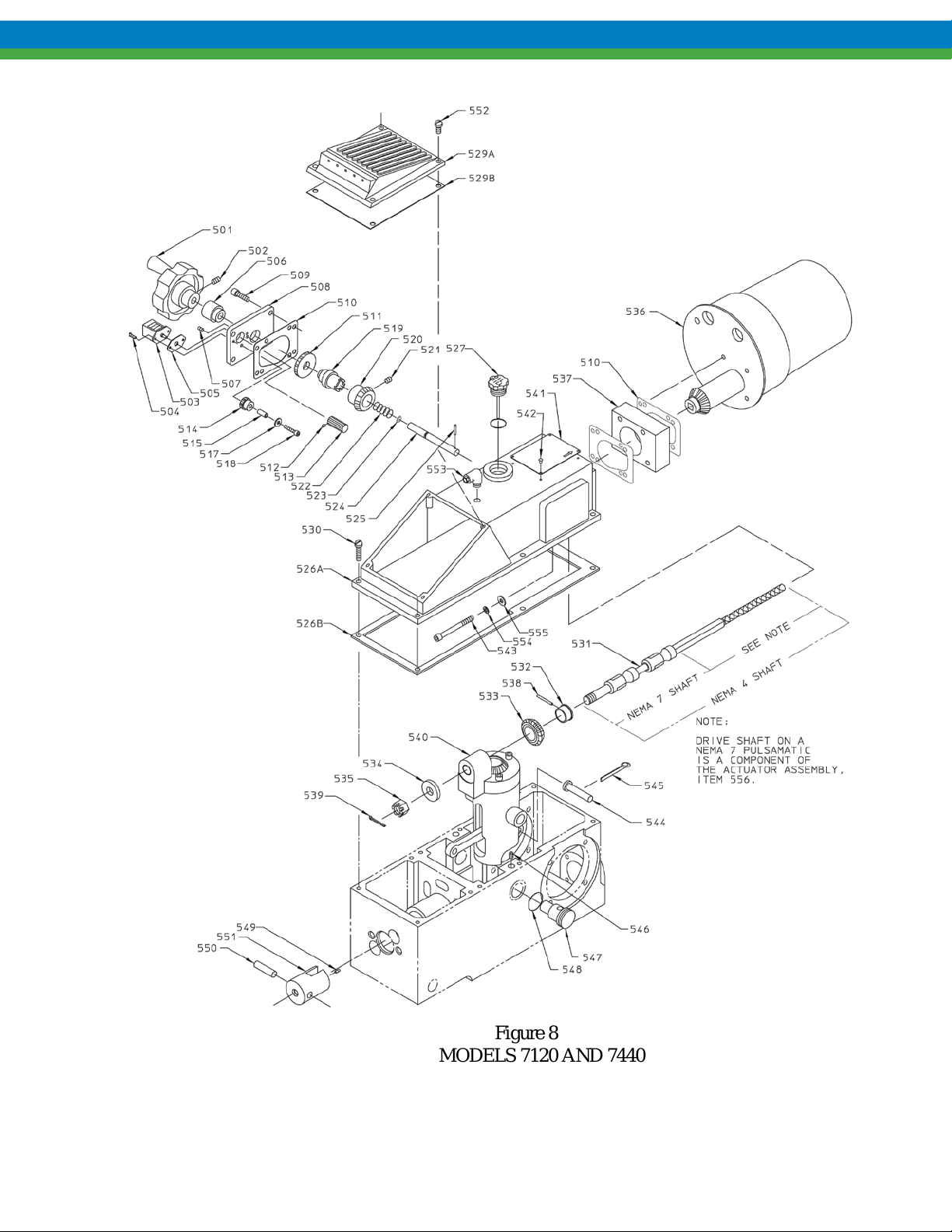
Figure 8
MODELS 7120 AND 7440
MODEL 7120/7440 -AE
AP00330
Page 28

25
501
Handwheel
1
502
Set Screw
1
503
Counter
1
504
Round Head Screw
2
505
Counter Gasket
1
506
Bushing
1
507
Set Screw
1
508
Mounting Plate
1
509
Cap Screw
4
510
Gasket
5
511
Gear 48T
1
512
Gear 16T
1
513
Set Screw
1
514
Gear 22T
1
515
Spacer
1
516
Washer
1
517
Washer
1
518
Cap Screw
1
519
Insert
1
520
Miter Gear
1
521
Set Screw
1
522
Spring
1
523
o-Ring
1
524
Pin 1 525
Roll Pin
1
526A
Cover
1
526B
Cover Gasket
1
527
Dip Stick Assembly
1
CONTROL ASSEMBLY
PULSAMATIC CONTROL
(Reference Figure 8)
ITEM PA RT NAME QUANTITY
Page 29

26
529A
Breather Cover
1
529B
Diaphragm
1
530
Fillister Head Screw
6
531
Drive Shaft Assembly
1
532
Bushing
1
533
Miter Gear
1
534
Washer
1
535
Slotted Nut
1
536
Actuato r As sembly
1
537
Spacer
1
538
Pin
1
539
Cotter Pin
1
540
Housing Asse mbly
1
541
Warning Plate
1
542
Drive Screw
4
543
Cap Screw
4
544
Pin 1 545
Cotter Pin
1
546
Set Screw
2
547
Housing Bol t
2
548
o-Ring
2
549
Set Screw
1
550
Pin 1 551
Crosshead
1
552
Fillister Head Screw
4
553
Tube Fitting
1
500
7120/7440 PULSAmatic Control consists of
1
all the above components pre-assembled
Page 30

27
Figure 9
MODELS 7660 AND 8480
AP00331
Page 31

28
501
Handwheel
1
502
Set Screw
1
503
Counter
1
504
Round Head Screw
2
505
Counter Gasket
1
506
Bushing
1
507
Set Screw
1
508
Mounting Plate
1
509
Cap Screw
4
510
Gasket
5
511
Gear 48T
1
512
Gear 16T
1
513
Set Screw
1
514
Gear 22T
1
515
Spacer
1
516
Washer
1
517
Washer
1
18
Cap Screw
1
519
Insert
1
520
Miter Gear
1
521
Set Screw
1
522
Spring
1
523
o-Ring
1
524
Pin 1 525
Roll Pin
1
MODEL 7660/8480 -AE
CONTROL ASSEMBLY
PULSAMATIC CONTROL
(Reference Figure 9)
ITEM PART NAME QUANTITY
Page 32

29
526A
Cover
1
526B
Cover Gasket
1
527
Dip Stick Assembly
1
528A
Front Cover
1
528B
Diaphragm
1
529A
Cover Plate
1
529B
Gasket
1
530
Fillister Head Screw
10
531
Drive Shaft Assembly
1
532
Bushing
1
533
Miter Gear
1
534
Washer
1
535
Slotted Nut
1
536
Actuato r As sembly
1
537
Spacer
1
538
Pin
1
539
Cotter Pin
1
540
Housing Assembly
1
541
Warning Plate
1
542
Drive Screw
4
543
Cap Screw
4
544
Pin
1
545
Cotter Pin
1
546
Hex Head Bolt
3
547
Housing Bol t
2
548
Gasket
2
549
Set Screw
1
550
Pin
1
551
Crosshead
1
552
Fillister Head Screw
4
500
7660/8480 PULSAmatic Control consists
1
of all the above components pre-assembled
Page 33

30
This page is intentionally left blank.
Page 34

31
PSM418 H11
 Loading...