

Pulsafeeder PULSAlarm Pulsa, PULSAlarm Pulsar, PULSAlarm PulsaPro Installation, Operation & Maintenance Instructions Manual
PULSAlarm®
Installation, Operation &
Maintenance Instructio n
Models: Pulsa, Pulsar, PulsaPro
DEMKO 12 ATEX 1204081X
II 2 G Ex d IIB T5 Gb
II 2 D Ex tb IIIC T100°C Db IP66
IECEx UL 14.0118X
Ex d IIB T5 Gb
Ex tb IIIC T100°C Db IP66
Bulletin: IOM-PUL-1007 Rev E
THIS DOCUMENT CONTAINS CHARACTERISTICS CONTROLLED BY U.L. FILE # E186527; CHANGES REQUIRE AGENCY
APPROVAL.
LEAK DETECTION

Pulsafeeder Factory Service Policy
Should you experience a problem with your Pulsafeeder pump, first consult the
troubleshooting guide in your pump operation and maintenance manual. If the problem
is not covered or cannot be solved, please contact your local Pulsafeeder Sales
Representative or Pulsafeeder Technical Service Department for further assistance.
Trained individuals are available to diagnose your problem and arrange a solution.
Solutions may include purchasing a replacement unit or returning the PULSAlarm to the
factory for inspection and repair.
All returns require a Return Material Authorization (R.M.A.) number to be issued by
Pulsafeeder. Parts purchased to correct a warranty issue may be credited after
examination of the original parts by Pulsafeeder personnel. Parts returned for warranty
considerations which are good will be sent back freight collect.
Any field modifications will void the warranty. Out-of-warranty repairs will be subject to
Pulsafeeder's standard bench fees and testing costs associated with replacement
components.
This document describes product features controlled by IECEx / ATEX
requirements. Those features, and this document, cannot be changed without
notification or approval of the appropriate agency.
Copyright
Copyright © 2006 - 2015 Pulsafeeder, Inc. All rights reserved.
Information in this document is subject to change without notice. No part of this
publication may be reproduced, stored in a retrieval system or transmitted in any form or
any means electronic or mechanical, including photocopying and recording for any
purpose other than the purchaser’s personal use without the written permission of
Pulsafeeder.
2

Safety Considerations:
• Read and understand all related instructions and documentation before attempting to
install or maintain this equipment
• Observe all special instructions, notes, and cautions.
• Act with care and exercise good common sense and judgment during all installation,
adjustment, and maintenance procedures.
• Ensure that all safety and work procedures and standards that are applicable to your
company and facility are followed during the installation, maintenance, and operation of
this equipment.
Notice
Information and specifications in this document are subject to change without notice.
Trademarks
Pulsa Series® and PULSAlarm® are registered trademarks of Pulsafeeder, Inc.
Revision History
Revision Implemented
By
B Engineering 04/27/2007 Technical
C Engineering,
Quality,
Compliance
D Engineering 03/03/2016 Technical
E Technical Service 05/31/2017 Aftermarket
Revision
Date
04/07/2015 Technical
Approved
By
Service
Service
Service
Manager
Approval
Date
04/27/2007 Material reference to “PTFE”
04/07/2015
03/03/2016
06/02/2017 Modify switch trip point settings and rem ove
Reason
Remove references to PULSAlarm®
Vacuum offering. Add ATEX and IECEx
information, general updates.
Modify temperature and code
information on front and back cover only
paragraph 7.4 for vacuum system priming.
3

Table of Contents
Contents
1.0 Conventions ........................................................................................................................ 5
2.0 Introduction ......................................................................................................................... 6
3.0 Foreword .............................................................................................................................. 6
4.0 ATEX / IECEx Nameplate and Marking ............................................................................... 7
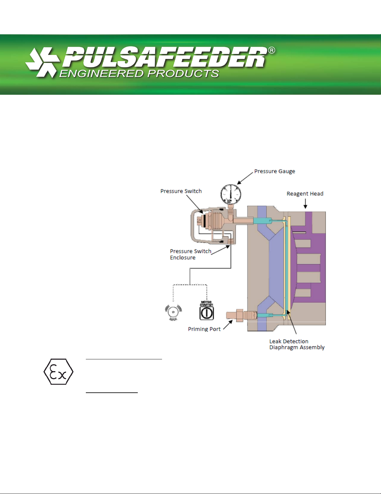
5.0 Description and Theory of Operation ................................................................................. 9
5.1
PULSAlarm® Reagent Head .......................................................................................... 10
5.2
PULSAlarm® Leak Detection Diaphragm .................................................................... 10
5.3
Diaphragm Construction ............................................................................................. 11
6.0 Electrical ............................................................................................................................ 12
7.0 Setup for Pressure ............................................................................................................ 13
8.0 Pressure fill chamber ........................................................................................................ 17
9.0 Maintenance ...................................................................................................................... 19
9.1
Switch Setpoint Adjustment ........................................................................................ 19
10.0 PULSAlarm® Diaphragm Maintenance .................................................................... 20
11.0 PULSAlarm® Diaphragm Removal .......................................................................... 20
12.0 Inspection .................................................................................................................. 21
12.1 PULSAlarm® Diaphragm Reinstallation .................................................................. 21
4
A
Tips have been included within this bulletin to help the operator run the
1.0 Conventions
For the remainder of this bulletin, the following conventions are in effect.
WARNING DEFINES A CONDITION THAT COULD CAUSE DAMAGE TO BOTH THE
EQUIPMENT AND THE PERSONNEL OPERATING IT
IN ALL CASES WHERE THE WARNING SYMBOL IS MARKED IN ORDER TO FIND OUT THE
NATURE OF THE POTENTIAL HAZARDS AND ANY ACTIONS WHICH HAVE TO BE TAKEN
TO AVOID THEM
.
. THIS MANUAL MUST BE CONSULTED
CAUTION,
POSSIBILITY OF ELECTRIC SHOCK
Notes are general information meant to make operating the equipment
easier. For information on overall pump operation and maintenance, refer to
the
Installation, Operation, and Maintenance manual specific to the model
of pump in
PULSAlarm® ® leak
question. The information in this bulletin pertains only to the
detection system supplied as an option on
Pulsafeeder PULSA/PULSAR Series pumps
equipment in the most efficient manner possible. These “Tips” are drawn
from the knowledge and experience of our staff engineers, and input from
the field.
5

2.0 Introduction
The PULSAlarm® ® is a microprocessor based stroke length control device for use with
the PULSA diaphragm-metering pump. It has been designed to operate in a variety of
industrial environments.
3.0 Foreword
The pumps to which these “instructions” refer to are designed for use in industrial areas
and therefore cannot be treated as retail products. The present documentation gives
instructions to be used by qualified personnel only. It must be used in compliance with
the regulations, laws and technical standards in force and cannot, under any
circumstances, take the place of plant standard or additional regulations, including any
which are not legally enforceable, which have been issued with the scope of ensuring
safety.
Equipment with special manufacturing or constructive variances may differ in details with
respect to this description.
In case of any difficulty, please contact PULSAFEEDER, INC. Technical Service.
The PULSAlarm® is rated for NEMA 7 locations as identified on the nameplate.
The PULSAlarm® complies with both ATEX and IEC IECEx standards.
The following standards apply to this product:
IEC 60079-0 6
IEC 60079-1 6
IEC 60079-31 1
EN 60079-0:2012+A11:2013
EN 60079-1:2007
EN 60079-31:2009
th
Edition
th
Edition
st
Edition
6
4.0 ATEX / IECEx Nameplate and Marking
All pumps bear a standard rating nameplate on which it is possible to read, apart
from functional data, all data required for universal identification.
Conduit connections
Conduit connections can carry fluids and vapors into the PULSAlarm®
causing damage and void the warranty. Care should be taken when
installing conduit to protect against fluid/vapor entry. In accordance with
any applicable codes provide sealed entries and conduit drains near the
point of entry as required. For installation purposes, the conduit glands on
the PULSAlarm® are .50-14 NPT.
To reduce the risk of ignition of hazardous atmospheres, conduit runs must
have a sealing fitting connected within 18 inches of the enclosure for
Division applications. For Zone applications, a seal shall be installed within
50 mm of the enclosure.
7
 Loading...