

Page 1
Standard Product Operations
27101 Airport Rd., Punta Gorda, FL 33982
Tel: (941) 575-3800 Tel: (800) 333-6677
Fax: (941) 575-4085 Fax: (800) 456-4085
spotech@pulsa.com www.Pulsafeeder.com
Manufacturers of Quality Pumps,
Controls, and Systems
Installation, Operation and Maintenance
Manual
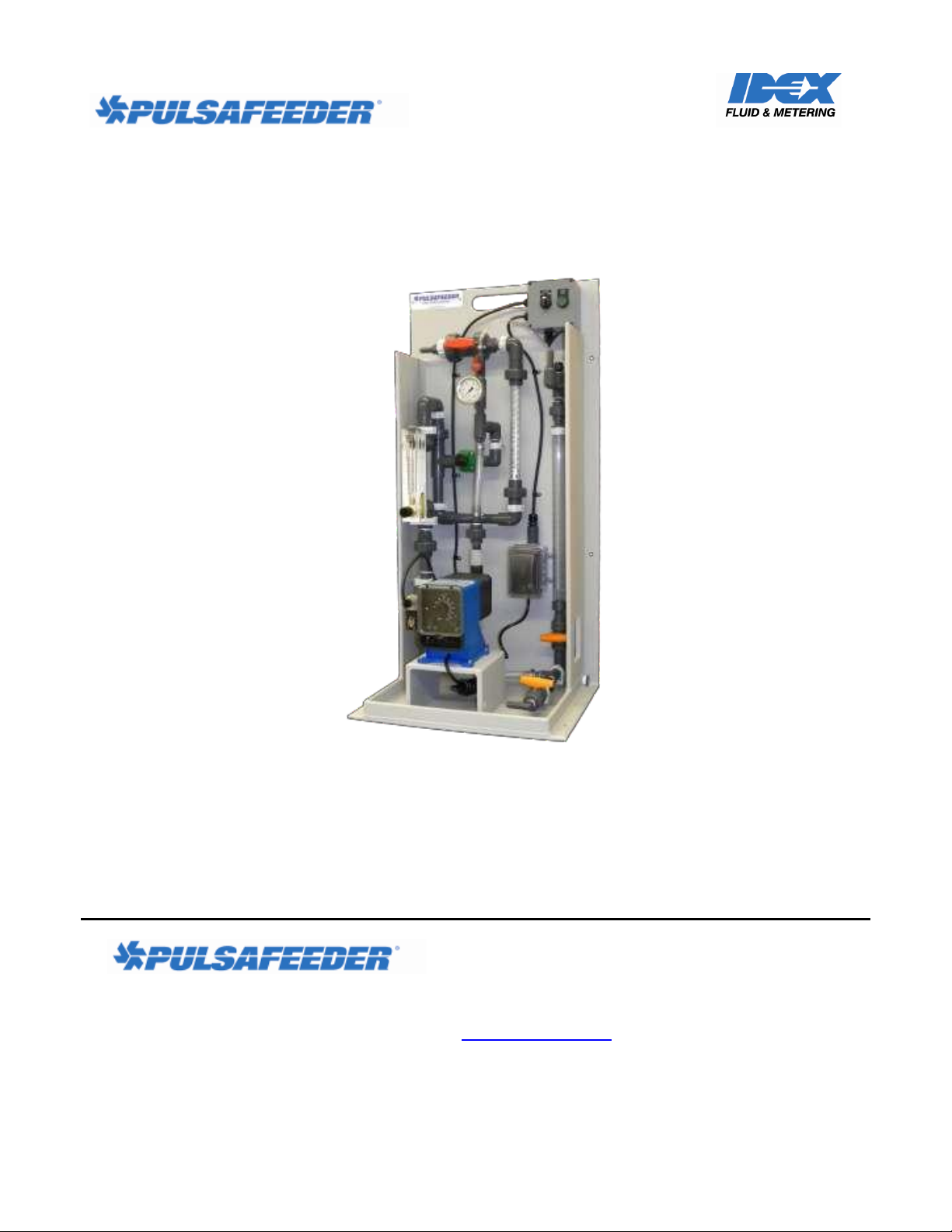
Manual Polymer Makedown Systems
72-910-MPMDS-E Rev A
Page 2

Manual Polymer Makedown Systems
Installation, Operation and Maintenance Manual
Pulsafeeder Factory Service Policy
Should you experience a problem with your Polymer Makedown System, first consult the
troubleshooting guide in this operation and maintenance manual, as well as the information in the
manual for your Pulsatron pump. If the problem is not covered or cannot be solved, please contact
your local Pulsafeeder Sales Representative or Distributor, or our Technical Services Department for
further assistance.
Trained technicians are available to diagnose your problem and arrange a solution. Solutions may
include purchase of replacement parts or returning the unit to the factory for inspection and repair. All
returns require a Return Authorization number to be issued by Pulsafeeder. Parts purchased to correct
a warranty issue may be credited after an examination of original parts by Pulsafeeder. Warranty parts
returned as defective which test good will be sent back freight collect. No credit will be issued on any
replacement electronic parts.
Any modifications or out-of-warranty repairs will be subject to bench fees and costs associated with
replacement parts.
Copyright ©2013 Pulsafeeder, Inc. All rights reserved.
Information in this document is subject to change without notice. No part of this publication may be
reproduced, stored in a retrieval system or transmitted in any form or any means electronic or
mechanical, including photocopying and recording for any purpose other than the purchaser’s personal
use without the written permission of Pulsafeeder, Inc.
72-910-MPMDS-E Rev A
ii
Page 3

Manual Polymer Makedown Systems
Installation, Operation and Maintenance Manual
Table of Contents
Topic Page
Introduction ........................................................................................................... 4
Safety .................................................................................................................... 5
Skid Layout and Component Descriptions ........................................................... 6
Systems Overview ................................................................................................ 7
Supply Side ..................................................................................................... 7
Process Side .................................................................................................... 8
Installation ............................................................................................................ 9
Owner Installed Piping/Tubing, & Electrical ................................................. 9
Initial System Start ............................................................................................. 10
Initial Prime .................................................................................................. 11
Polymer Makedown Process ............................................................................... 12
72-910-MPMDS-E Rev A
iii
Page 4

Manual Polymer Makedown Systems
Installation, Operation and Maintenance Manual
Introduction
Congratulations! With the Pulsafeeder Pre-Engineered Polymer Makedown System, you have the
finest polymer makedown equipment platform available. This system includes the essential elements
for successful installation and operation of your system(s). You are encouraged to:
READ THIS MANUAL!
Pulsafeeder Pre-Engineered Polymer Makedown Systems are designed to support multi-pump
installations for injection. The skid components (valves, gauges, interconnecting piping, etc.) are
furnished to meet your specified operational requirements. The Dosing Pump(s), per se, may be
furnished separately, so installation, operation and maintenance instructions for pump(s) are located
elsewhere.
72-910-MPMDS-E Rev A
Introduction Page 4
Page 5
Manual Polymer Makedown Systems
!
WARNING
Do NOT use Pulsafeeder Systems (or Pulsafeeder Pumps) for flammable liquids.
!
WARNING
Prior to working on any portion of the System, disconnect pump(s) from power supply,
de-pressurize the system and drain chemicals from the lines.
!
WARNING
Inspect tubing regularly and replace as necessary.
When inspecting tubing, wear protective clothing and safety glasses.
!
CAUTION
If skid is exposed to sunlight, use UV-resistant tubing.
!
CAUTION
Follow directions and warnings provided with chemicals from the chemical
manufacturer. User/owner is responsible for determining chemical compatibility with
chemical feed pump(s) and system components.
!
CAUTION
Secure chemicals, metering pump(s) and system, making them inaccessible to
children, pets and unauthorized personnel.
!
WARNING
Always wear protective clothing including gloves and safety goggles when
working on or near chemical metering pumps and systems.
Installation and start-up of chemical dosing system will require both mechanical
(plumbing) and electrical work. Only qualified and licensed plumbers and
electricians should perform this.
!
CAUTION
Installation, Operation and Maintenance Manual
Safety
Your safety is of the utmost concern to Pulsafeeder. Dosing pumps and systems can handle harsh or
toxic chemicals and exposure can lead to serious injury or death. Always wear appropriate protective
clothing (for example, safety glasses, gloves, coveralls, etc.) and follow safe handling procedures. Pay
attention to what you’re doing and note safety advisories where they are shown throughout this
manual. Some examples of safety issues and precautions for Pulsafeeder Pre-Engineered Polymer
Makedown Systems are:
72-910-MPMDS-E Rev A
Safety Page 5
Page 6
Manual Polymer Makedown Systems
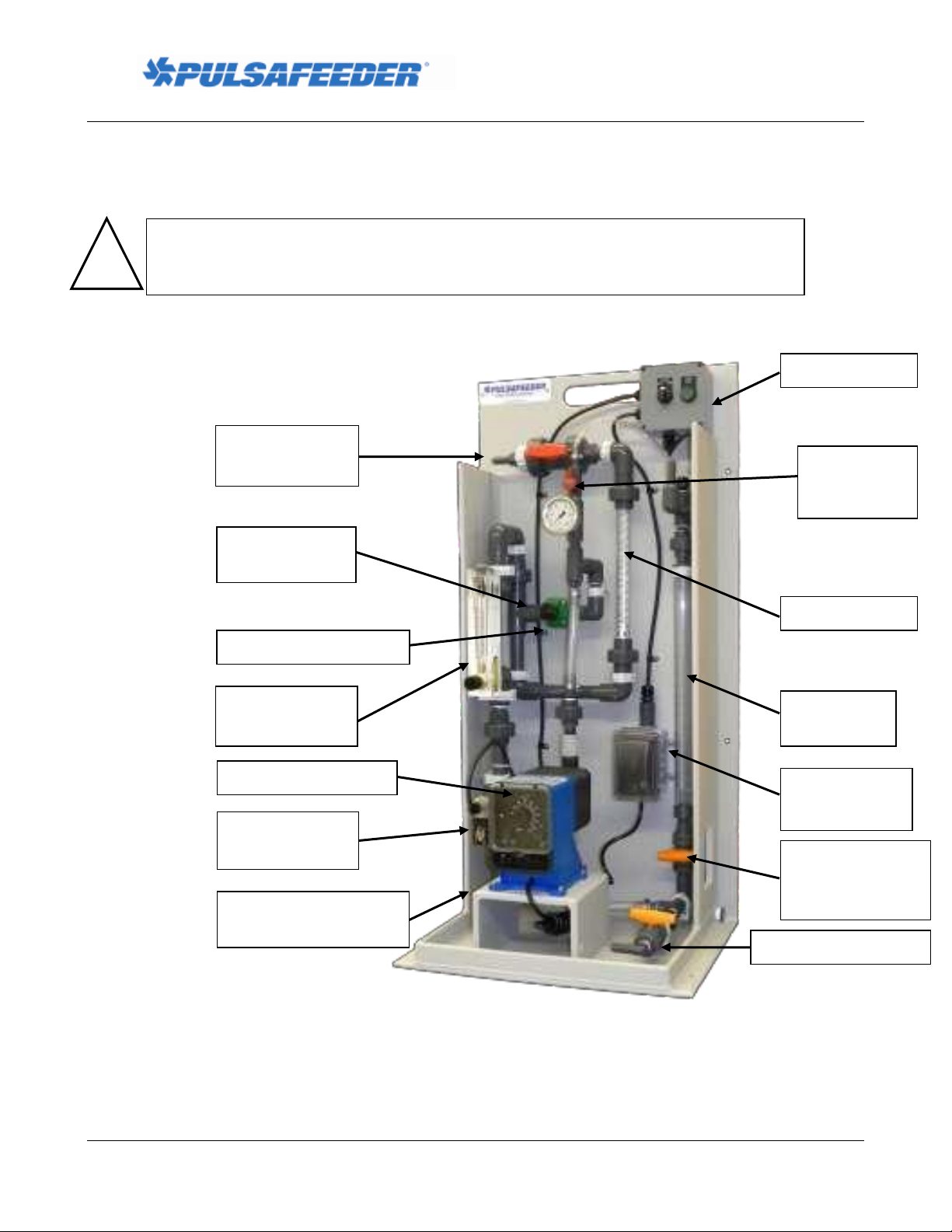
Control Panel
Calibration
Column
Flow Indicator,
Water
Static Mixer
Back Pressure Valve
Water Inlet, Left Side,
Back or Front
Made-down
Polymer Outlet
!
CAUTION
Never remove the Tank Cover without removing power to the Polymer
Makedown System first. The tank mixer blades (inside the tank) can cause serious
harm or even death if allowed to come in contact with a person during operation.
Neat Polymer
Injection Quill
Neat Polymer Inlet
Neat Polymer Pump
Pump Power
Supply
Calibration
Column Fill
Valve
Figure 1
Water Inlet
Solenoid Valve
Calibration
Column Supply
Valve
Installation, Operation and Maintenance Manual
System Layout and Components
Figure 1, below, illustrates a static mixer polymer makedown system with integrated control. Note the
various components and their descriptions as they apply to your system.
72-910-MPMDS-E Rev A
Skid Layout and Components Page 6
Page 7
Manual Polymer Makedown Systems
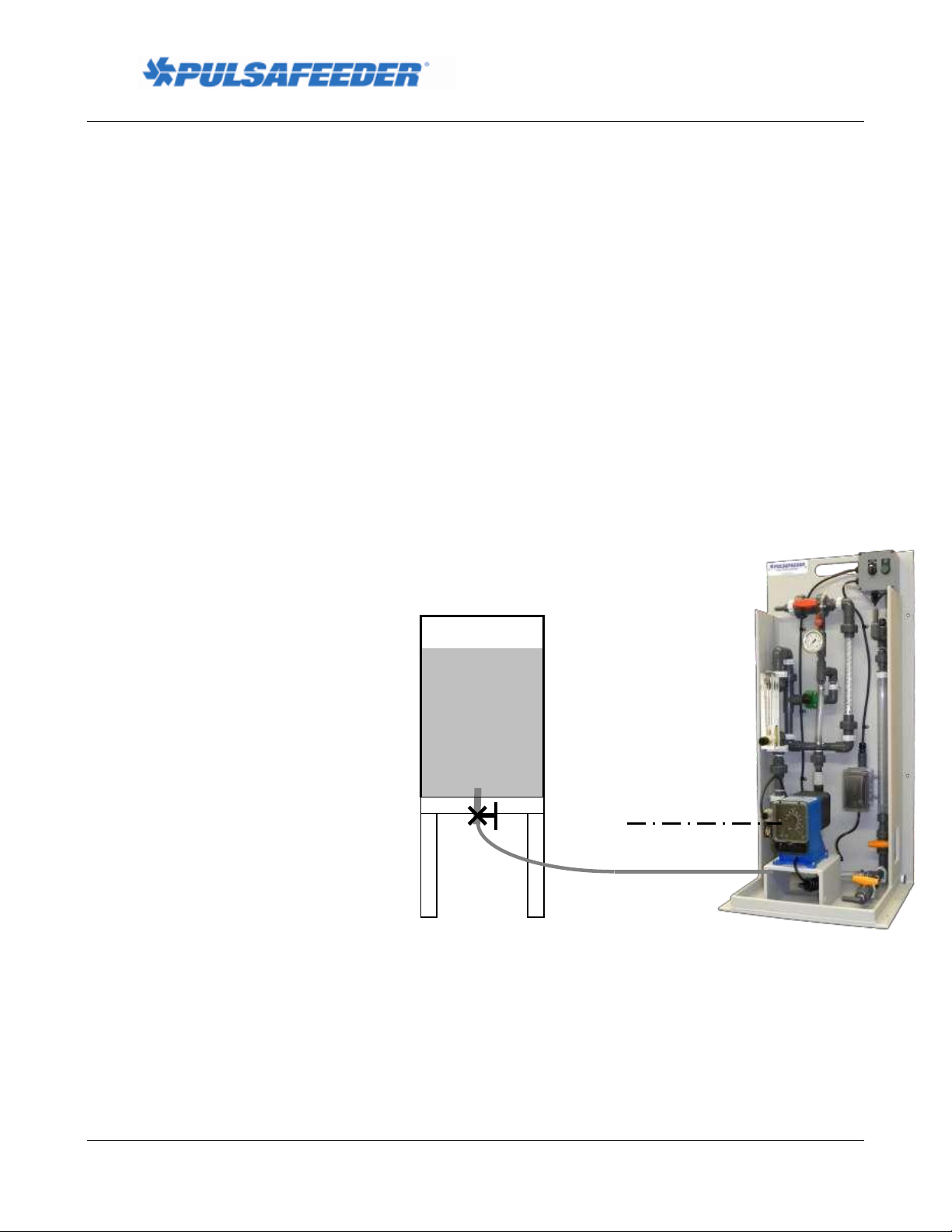
Pump
Neat
Polymer
Tank
Supply
Line
Figure 3
Flooded Suction
Flooded Suction
This is the most trouble free type of installation.
Since the Supply Line tubing is filled with
chemical, priming is accomplished quickly and the
chance of losing prime is reduced.
Recommended for very low flow rate applications.
e.g. 2 ml/hr, or where pumping solutions such as
sodium hypochlorite or hydrogen peroxide which
can form air bubbles.
Supply Line should gradually slope downward
from the Solution Tank to the Skid Suction
Connection.
It is strongly recommended to add a drain
provision on the suction side to facilitate
emptying and flushing of the system for
maintenance.
Installation, Operation and Maintenance Manual
Systems Overview
The Polymer Makedown System is designed to inject neat polymer into a clean water stream and to
agitate this mixture through a static mixer causing the polymer strands to expand into a ‘made-down’
aqueous solution. The solution is stored in the polymer solution day-tank and mixed occasionally with
the rotary mixer located in the tank. The tank outlet is typically connected to the dosing pump(s) which
inject the solution into the process application. The dosing pump(s) are not provided with the Polymer
Makedown System and are not powered by the System.
Supply Side
Dosing chemicals are usually sourced from a barrel or tote container. The source must be located
above the centerline of the neat polymer pump which is referred to as a “flooded suction”. Because
Neat Polymer is a high viscosity fluid, the supply should never be located below the centerline of the
pump(s) which is referred to as “suction lift.” Connections to and from the Neat Polymer Tank are
most commonly made with flexible hose or tubing although they may be made with hard piping. The
Neat Polymer Tank should be covered to prevent contamination.
72-910-MPMDS-E Rev A
Skid Layout and Components Page 7
Page 8

Manual Polymer Makedown Systems
Installation, Operation and Maintenance Manual
Process side
The Polymer Makedown System is not equipped with backflow prevention to protect against process
fluid flowing back into the municipal water supply should the process pressure become greater than the
water supply pressure. Please refer to all local, state and national codes for the proper backflow
prevention requirements based on your type of installation.
72-910-MPMDS-E Rev A
Skid Layout and Components Page 8
Page 9

Manual Polymer Makedown Systems
!
CAUTION
Some dosing chemicals will react with water, e.g., acids, polymers, etc. Check MSDS
for the chemical to be handled. If adverse reaction with water is indicated, ensure that
all portions of the skid piping, its components (and the pump) are free from water prior
to filling skid system with chemical.
CAUTION
If skid is exposed to sunlight, use UV-resistant tubing.
!
WARNING
Ensure that for all piping, tubing, fittings and other appurtenances, their materials are
compatible with the liquid to be pumped and the design is suitable for the pressures and
temperatures of the application. System design must ensure safety for operation and
maintenance as well as for anyone who may be in proximity to the system.
Failure to do so may result in damage to equipment, personal injury or death.
Installation, Operation and Maintenance Manual
Installation
Prior to attempting installation, familiarize yourself with the layout and components furnished with
your Pulsafeeder Polymer Makedown System. These vary from system to system – review the
documentation supplied with your order. Inspect your system for damage which may have occurred
during transit. If damage is discovered, immediately file a claim with the carrier and contact your
Pulsafeeder distributor for any required replacement parts or components.
All systems (and pumps) have been tested with water at the factory.
Polymer Makedown Systems are to be floor-mounted only. Mounting holes are provided on the skid
for floor mounting. Securely attach skid and the day-tank to the floor, in a position to prevent falling
or tipping.
Securely attach the provided ¾” x ½” diameter x 10’ long tubing from the system’s Made-down
Polymer Outlet to the Day-tank’s Made-down Polymer Inlet, on the hose barbs with the hose clamps
provided; refer to Figure 1 on page 6. It is best to cut this tubing to the desired length prior to
installation, and be sure to support the tubing adequately over its length as its weight will increase
when filled with made-down polymer.
Installation area should provide ease of access to skid components (and pumps) and the area should be
kept free of clutter to enable safe operation and maintenance.
Note that pumps/motors are designed for ambient temperatures of 104OF (40OC) maximum.
It is preferable that skid systems (and pumps) be located out of direct sunlight. If skid system is
exposed to sunlight, provide protection for the pump/motor to prevent overheating and UV damage.
Owner-Installed Piping/Tubing
The next series of steps are the connection of your piping/tubing which include the neat polymer
supply line and tank outlet for made-down polymer supply to the system.
These are your responsibility.
72-910-MPMDS-E Rev A
Skid Layout and Components Page 9
Page 10

Manual Polymer Makedown Systems
Installation, Operation and Maintenance Manual
Neat Polymer Supply Line
This line connects the source of the neat polymer to the Pulsafeeder Polymer Makedown System.
Please refer to Figure 1 on page 6. The neat polymer source must be located above the centerline of
the pump (flooded suction condition); ensure that the suction line has a gradual downward slope from
the tank to the skid suction connection. The purpose of this is to prevent air pocket(s) in the suction
line which could affect proper operation of the pump. Include whatever provisions you consider
necessary to facilitate maintenance and operation such as isolation valve(s), drain and/or flush
connections, etc., making sure that this sub-system enables SAFE OPERATION.
Discharge Line
This line connects the Pulsafeeder Polymer Makedown System to your served process. Please refer to
Figure 1 on page 6. If the injection point is below the dosing chemical source or if injecting into a low
pressure area such as the suction of a pump, an anti-siphon/ back pressure valve should be located as
close as possible to the injection point to prevent unwanted chemical feeding. Include whatever
provisions you consider necessary to facilitate maintenance and operation such as isolation valve(s),
drain and/or flush connections, etc., making sure that this sub-system enables SAFE OPERATION.
Electrical Connection
The control panel is provided with a standard plug for connection to 115V (+/-10%), 20A power to
operate. Be sure that the selector switch is in the “OFF” position before power is connected.
Initial Prime
The neat polymer pump must be primed before it can function within the system. This will require an
initial start of the pump. It is recommended that the system piping be filled with water before polymer
is introduced to the system.
1. Turn the Main Selector Switch to the “Flush” position (center) to initiate water flow.
2. Once water fills the system and begins to flow out of the system discharge, turn the Main
Selector Switch to the “OFF” position to terminate water flow.
3. Open the Calibration Column Fill Valve; this aids in pump priming by providing a vent path to
the calibration column, bypassing the Back Pressure Valve.
4. Depress the green “Prime” button to start the Neat Polymer Pump.
5. Observe polymer flow through the clear braided tubing connecting the pump discharge to the
system piping; when present the pump is primed.
6. Release the “Prime” button to stop the Neat Polymer Pump.
7. Close the Calibration Column Fill Valve.
8. The system is now ready to operate.
72-910-MPMDS-E Rev A
Skid Layout and Components Page 10
Page 11

Manual Polymer Makedown Systems
Installation, Operation and Maintenance Manual
Polymer Makedown Process
Process Start
This polymer makedown system utilizes a continuous makedown process. The makedown process is
started by moving the Main Selector Switch to the “Run” position. This will open the Inlet Water
Solenoid Valve and energize the Neat Polymer Injection Pump to add polymer to the water flow. The
system will produce made-down polymer continuously while in the “Run” mode.
System Adjustment – Refer to Figure 1
The Water Flow Meter can be adjusted to achieve the desired water flow rate by turning the
adjustment knob until the indicator ball settles on the correct flow rate.
Open the Calibration Column Fill Valve to divert neat polymer to the calibration column until
full; close the fill valve. Simultaneously open the Calibration Column Supply Valve at the
bottom of the column while closing the Neat Polymer Inlet Valve, and time the drawdown of
polymer from the column for 30 seconds. Record the volume consumed and simultaneously
close the Calibration Column Supply Valve at the bottom of the column while opening the Neat
Polymer Inlet Valve.
Calculate the actual flow rate of the pump and adjust to the desired rate. Repeat the calibration
process to confirm.
Adjust pump output as required and repeat calibration process to confirm adjustment.
System Operation for Polymer Makedown
Turn the Main Selector Switch to the ‘Run’ position; leave in this position for the time required
to produce the made-down polymer required.
When complete, turn the Main Selector Switch to the ‘Flush’ position for approximately 1
minute. This allows incoming water flow to clean the injector nozzle and the static mixer of
residual polymer.
CAUTION: Failure to flush the system could result in significant fouling of the injector
nozzle, static mixer and related piping as the made-down polymer solidifies over time before
the next cycle.
When the flush operation is complete, turn the Main Selector Switch to the ‘Off’ position.
72-910-MPMDS-E Rev A
Skid Layout and Components Page 11
 Loading...