

Page 1
Standard Product Operations
27101 Airport Rd., Punta Gorda, FL 33982
Tel: (941) 575-3800 Tel: (800) 333-6677
Fax: (941) 575-4085 Fax: (800) 456-4085
spotech@pulsa.com www.Pulsafeeder.com
Manufacturers of Quality Pumps,
Controls, and Systems
Installation, Operation and Maintenance
Manual
Automatic Polymer Makedown Systems
72-910-APMDS-E Rev A
Page 2

Automatic Polymer Makedown Systems
Installation, Operation and Maintenance Manual
Pulsafeeder Factory Service Policy
Should you experience a problem with your Polymer Makedown System, first consult the
troubleshooting guide in this operation and maintenance manual, as well as the information in the
manual for your Pulsatron pump. If the problem is not covered or cannot be solved, please contact
your local Pulsafeeder Sales Representative or Distributor, or our Technical Services Department for
further assistance.
Trained technicians are available to diagnose your problem and arrange a solution. Solutions may
include purchase of replacement parts or returning the unit to the factory for inspection and repair. All
returns require a Return Authorization number to be issued by Pulsafeeder. Parts purchased to correct
a warranty issue may be credited after an examination of original parts by Pulsafeeder. Warranty parts
returned as defective which test good will be sent back freight collect. No credit will be issued on any
replacement electronic parts.
Any modifications or out-of-warranty repairs will be subject to bench fees and costs associated with
replacement parts.
Copyright ©2013 Pulsafeeder, Inc. All rights reserved.
Information in this document is subject to change without notice. No part of this publication may be
reproduced, stored in a retrieval system or transmitted in any form or any means electronic or
mechanical, including photocopying and recording for any purpose other than the purchaser’s personal
use without the written permission of Pulsafeeder, Inc.
72-910-APMDS-E Rev A
ii
Page 3

Automatic Polymer Makedown Systems
Installation, Operation and Maintenance Manual
Table of Contents
Topic Page
Introduction ........................................................................................................... 4
Safety .................................................................................................................... 5
Skid Layout and Component Descriptions ........................................................... 6
Systems Overview ................................................................................................ 7
Supply Side ..................................................................................................... 7
Process Side .................................................................................................... 8
Installation ............................................................................................................ 9
Owner Installed Piping/Tubing, & Electrical ................................................. 9
Schematic ............................................................................................................ 11
Initial System Start ............................................................................................. 12
Initial Prime .................................................................................................. 12
System Operation ................................................................................................ 13
Polymer Makedown Process ............................................................................... 13
72-910-APMDS-E Rev A
iii
Page 4

Automatic Polymer Makedown Systems
Installation, Operation and Maintenance Manual
Introduction
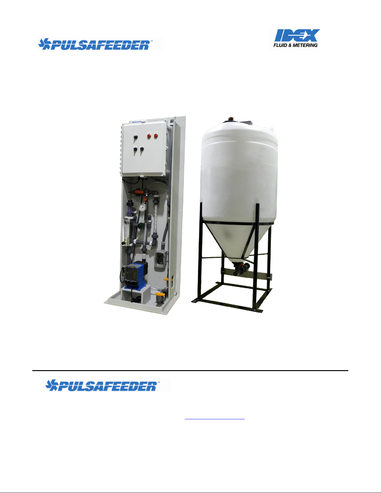
Congratulations! With the Pulsafeeder Pre-Engineered Polymer Makedown System, you have the
finest polymer makedown equipment platform available. This system includes the essential elements
for successful installation and operation of your system(s). You are encouraged to:
READ THIS MANUAL!
Pulsafeeder Pre-Engineered Polymer Makedown Systems are designed to support multi-pump
installations for injection. The skid components (valves, gauges, interconnecting piping, etc.) are
furnished to meet your specified operational requirements. The Dosing Pump(s), per se, may be
furnished separately, so installation, operation and maintenance instructions for pump(s) are located
elsewhere.
72-910-APMDS-E Rev A
Introduction Page 4
Page 5
Automatic Polymer Makedown Systems
!
WARNING
Do NOT use Pulsafeeder Systems (or Pulsafeeder Pumps) for flammable liquids.
!
WARNING
Prior to working on any portion of the System, disconnect pump(s) from power supply,
de-pressurize the system and drain chemicals from the lines.
!
WARNING
Inspect tubing regularly and replace as necessary.
When inspecting tubing, wear protective clothing and safety glasses.
!
CAUTION
If skid is exposed to sunlight, use UV-resistant tubing.
!
CAUTION
Follow directions and warnings provided with chemicals from the chemical
manufacturer. User/owner is responsible for determining chemical compatibility with
chemical feed pump(s) and system components.
!
CAUTION
Secure chemicals, metering pump(s) and system, making them inaccessible to
children, pets and unauthorized personnel.
!
WARNING
Always wear protective clothing including gloves and safety goggles when
working on or near chemical metering pumps and systems.
Installation and start-up of chemical dosing system will require both mechanical
(plumbing) and electrical work. Only qualified and licensed plumbers and
electricians should perform this.
!
CAUTION
Installation, Operation and Maintenance Manual
Safety
Your safety is of the utmost concern to Pulsafeeder. Dosing pumps and systems can handle harsh or
toxic chemicals and exposure can lead to serious injury or death. Always wear appropriate protective
clothing (for example, safety glasses, gloves, coveralls, etc.) and follow safe handling procedures. Pay
attention to what you’re doing and note safety advisories where they are shown throughout this
manual. Some examples of safety issues and precautions for Pulsafeeder Pre-Engineered Polymer
Makedown Systems are:
72-910-APMDS-E Rev A
Safety Page 5
Page 6
Automatic Polymer Makedown Systems
!
CAUTION
Never remove the Tank Cover without removing power to the Polymer
Makedown System first. The tank mixer blades (inside the tank) can cause serious
harm or even death if allowed to come in contact with a person during operation.
Installation, Operation and Maintenance Manual
System Layout and Components
Figure 1, below, illustrates a static mixer polymer makedown system with integrated control and daytank. This system can be used for two different chemicals or for redundant pump operation with one
chemical. Your skid system may be less complex than this. Note the various components and their
descriptions as they apply to your system.
72-910-APMDS-E Rev A
Skid Layout and Components Page 6
Page 7

Automatic Polymer Makedown Systems
Mixer, Tank
Level Sensor
Control Panel
Calibration
Column
Flow Indicator,
Water
Static Mixer
Made-down
Polymer Day
Tank
Back Pressure Valve
Water Inlet, Left Side, Back or Front
Mounting Base
Made-down
Polymer Inlet
Made-down
Polymer Outlet
to Day-tank
Neat Polymer
Injection Quill
Neat Polymer Inlet
Neat Polymer Pump
Pump Power Supply
Calibration
Column Fill
Valve
Low Flow Switch
Figure 1
Made-down
Polymer outlet
tp Process
Installation, Operation and Maintenance Manual
72-910-APMDS-E Rev A
Skid Layout and Components Page 7
Page 8

Automatic Polymer Makedown Systems
Pump
Neat
Polymer
Tank
Supply
Line
Figure 3
Flooded Suction
Flooded Suction
This is the most trouble free type of installation.
Since the Supply Line tubing is filled with
chemical, priming is accomplished quickly and the
chance of losing prime is reduced.
Recommended for very low flow rate applications.
e.g. 2 ml/hr, or where pumping solutions such as
sodium hypochlorite or hydrogen peroxide which
can form air bubbles.
Supply Line should gradually slope downward
from the Solution Tank to the Skid Suction
Connection.
It is strongly recommended to add a drain
provision on the suction side to facilitate
emptying and flushing of the system for
maintenance.
Installation, Operation and Maintenance Manual
Systems Overview
The Polymer Makedown System is designed to inject neat polymer into a clean water stream and to
agitate this mixture through a static mixer causing the polymer strands to expand into a ‘made-down’
aqueous solution. The solution is stored in the polymer solution day-tank and mixed occasionally with
the rotary mixer located in the tank. The tank outlet is typically connected to the dosing pump(s) which
inject the solution into the process application. The dosing pump(s) are not provided with the Polymer
Makedown System and are not powered by the System.
Supply Side
Dosing chemicals are usually sourced from a barrel or tote container. The source must be located
above the centerline of the neat polymer pump which is referred to as a “flooded suction”. Because
Neat Polymer is a high viscosity fluid, the supply should never be located below the centerline of the
pump(s) which is referred to as “suction lift.” Connections to and from the Neat Polymer Tank are
most commonly made with flexible hose or tubing although they may be made with hard piping. The
Neat Polymer Tank should be covered to prevent contamination.
Process side
72-910-APMDS-E Rev A
Skid Layout and Components Page 8
Page 9

Automatic Polymer Makedown Systems
Installation, Operation and Maintenance Manual
The injection point in the served process or system must be higher than the top of the Solution Supply
Tank to prohibit gravity feeding unless suitable backpressure is always present at the injection point.
In applications where the injection point is below the Solution Supply Tank (example – injection
into a well) or where the injection point may be at reduced pressure (example – injection into the
suction side of a pump), installation of an anti-siphon valve in the process feed line will prevent gravity
feeding.
Note: For some applications where air or gas may form in the suction line, this may interrupt flow.
In this case, it may be desirable to add a “Proof of Flow” device on the process side to alert if chemical
injection flow is somehow interrupted. Contact your Pulsafeeder distributor.
72-910-APMDS-E Rev A
Skid Layout and Components Page 9
Page 10

Automatic Polymer Makedown Systems
!
CAUTION
Some dosing chemicals will react with water, e.g., acids, polymers, etc. Check MSDS
for the chemical to be handled. If adverse reaction with water is indicated, ensure that
all portions of the skid piping, its components (and the pump) are free from water prior
to filling skid system with chemical.
CAUTION
If skid is exposed to sunlight, use UV-resistant tubing.
!
WARNING
Ensure that for all piping, tubing, fittings and other appurtenances, their materials are
compatible with the liquid to be pumped and the design is suitable for the pressures and
temperatures of the application. System design must ensure safety for operation and
maintenance as well as for anyone who may be in proximity to the system.
Failure to do so may result in damage to equipment, personal injury or death.
Installation, Operation and Maintenance Manual
Installation
Prior to attempting installation, familiarize yourself with the layout and components furnished with
your Pulsafeeder Polymer Makedown System. These vary from system to system – review the
documentation supplied with your order. Inspect your system for damage which may have occurred
during transit. If damage is discovered, immediately file a claim with the carrier and contact your
Pulsafeeder distributor for any required replacement parts or components.
All systems (and pumps) have been tested with water at the factory.
Polymer Makedown Systems are to be floor-mounted only. Mounting holes are provided on the skid
for floor mounting. Securely attach skid and the day-tank to the floor, in a position to prevent falling
or tipping.
Securely attach the provided ¾” x ½” diameter x 10’ long tubing from the system’s Made-down
Polymer Outlet to the Day-tank’s Made-down Polymer Inlet, on the hose barbs with the hose clamps
provided; refer to Figure 1 on page 6. It is best to cut this tubing to the desired length prior to
installation, and be sure to support the tubing adequately over its length as its weight will increase
when filled with made-down polymer.
Installation area should provide ease of access to skid components (and pumps) and the area should be
kept free of clutter to enable safe operation and maintenance.
Note that pumps/motors are designed for ambient temperatures of 104OF (40OC) maximum.
It is preferable that skid systems (and pumps) be located out of direct sunlight. If skid system is
exposed to sunlight, provide protection for the pump/motor to prevent overheating and UV damage.
Owner-Installed Piping/Tubing
The next series of steps are the connection of your piping/tubing which include the neat polymer
supply line and tank outlet for made-down polymer supply to the system.
These are your responsibility.
72-910-APMDS-E Rev A
Skid Layout and Components Page 10
Page 11

Automatic Polymer Makedown Systems
Installation, Operation and Maintenance Manual
Neat Polymer Supply Line
This line connects the source of the neat polymer to the Pulsafeeder Polymer Makedown System.
Please refer to Figure 1 on page 6. The neat polymer source must be located above the centerline of
the pump (flooded suction condition); ensure that the suction line has a gradual downward slope from
the tank to the skid suction connection. The purpose of this is to prevent air pocket(s) in the suction
line which could affect proper operation of the pump. Include whatever provisions you consider
necessary to facilitate maintenance and operation such as isolation valve(s), drain and/or flush
connections, etc., making sure that this sub-system enables SAFE OPERATION.
Discharge Line
This line connects the Pulsafeeder Polymer Makedown System to your served process. Please refer to
Figure 1 on page 6. If the injection point is below the dosing chemical source or if injecting into a low
pressure area such as the suction of a pump, an anti-siphon/ back pressure valve should be located as
close as possible to the injection point to prevent unwanted chemical feeding. Include whatever
provisions you consider necessary to facilitate maintenance and operation such as isolation valve(s),
drain and/or flush connections, etc., making sure that this sub-system enables SAFE OPERATION.
Electrical Connection
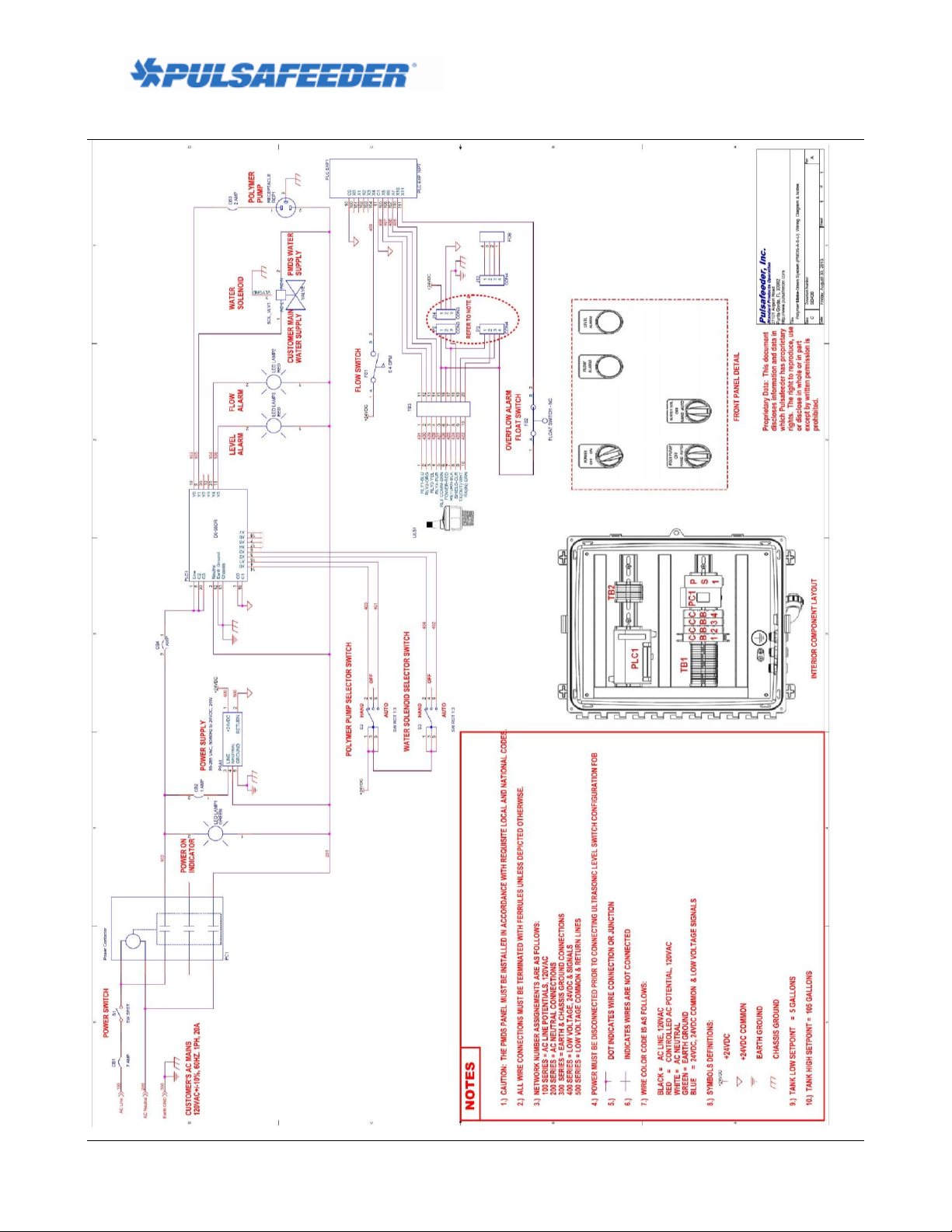
The control panel is provided with a standard plug for connection to 115V (+/-10%) , 20A power to
operate.
Electrical Schematic
Refer to diagram on page 11.
72-910-APMDS-E Rev A
Skid Layout and Components Page 11
Page 12
Automatic Polymer Makedown Systems
Installation, Operation and Maintenance Manual
72-910-APMDS-E Rev A
Skid Layout and Components Page 12
Page 13

Automatic Polymer Makedown Systems
Selecting the manual operation mode marked “HAND” for any of the switches
will operate that device without regard for any of the safety features or alarm
modes that may be active. All safety requirements are the responsibility of the
operator while in manual “HAND” mode.
!
CAUTION
Installation, Operation and Maintenance Manual
Initial System Start
Be sure that all selectors are in the “OFF” position before power is connected; this includes:
1. Main Power switch, marked “POWER”.
2. Neat Polymer Feed Pump switch, marked “POLY. PUMP”.
3. Water Inlet Solenoid Valve switch, marked “WATER SOL.”.
4. Polymer Tank Mixer switch, marked “MIXER”.
Initial Prime
The neat polymer pump must be primed before it can function within the system. This will require an
initial start of the pump. It is recommended that the system piping be filled with water before polymer
is introduced to the system.
1. Turn the Main Power switch to the “On” position.
2. Turn the Water Inlet Solenoid switch marked “WATER SOL.” to “HAND” position to initiate
water flow.
3. Once water starts to enter the Polymer Storage Tank, turn the Water Inlet Solenoid switch
marked “WATER SOL.” to “OFF” position to terminate water flow.
4. Open the Calibration Column Fill Valve; this aids in pump priming by providing a vent path to
the calibration column, bypassing the Back Pressure Valve.
5. Turn “POLY. PUMP” switch to “Hand” to start the Neat Polymer Pump.
6. Observe polymer flow through the clear braided tubing connecting the pump discharge to the
system piping; when present the pump is primed.
7. Turn “POLY. PUMP” switch to “OFF” to stop the Neat Polymer Pump.
8. Close the Calibration Column Fill Valve.
72-910-APMDS-E Rev A
Skid Layout and Components Page 13
Page 14

Automatic Polymer Makedown Systems
1/9 = 1 minute “ON” followed by 9 minutes “OFF”
4/6 = 4 minutes “ON” followed by 6 minutes “OFF”
7/3 = 7 minutes “ON” followed by 3 minutes “OFF”
10/0 = 10 minutes “ON” with no “OFF” time; continuous operation
Installation, Operation and Maintenance Manual
System Operation
1. After the Neat Polymer Pump is primed, turn the Main Power switch, marked “POWER” to the
“OFF” position.
2. Turn the Neat Polymer Feed Pump switch, marked “POLY. PUMP” to the “AUTO” position.
3. Turn the Water Inlet Solenoid Valve switch, marked “WATER SOL.” To the “AUTO”
position.
4. Optional: Turn the Polymer Tank Mixer switch, marked “MIXER” to the “AUTO” position.
5. Optional: Select the Mixer Cycle desired:
6. Turn the Main Power switch, marked “POWER” to the “ON” position; the unit will begin to
function automatically.
Polymer Makedown Process
o Process Start
This is a polymer makedown system utilizes a batch process sequence. The makedown
process is triggered to start when the high level switch in the storage tank is open, and the
low level switch in the tank changes from closed to open, indicating that the level in the
tank has just dropped below the low level.
o Polymer Makedown for Tank Fill
When triggered to start the controller will energize the Water Inlet Solenoid Valve to open,
allowing municipal water to flow into the system. This flow is verified by the condition of
the Flow Switch changing from Open to Closed contact. At the same time the Neat Polymer
Pump is energized to pump neat polymer into the water flow where it is ‘made-down’ into a
polymer solution and stored in the storage tank. This process continues until the High Level
switch is closed, leading to the process flush cycle.
Flow Switch Interrupt – When the Water Inlet Solenoid Valve is open, the Flow Switch
status should show Closed to verify water flow in the system, and otherwise show Open
indication that water flow has terminated. There are two alarm conditions that will be
triggered by the Flow Switch, causing the Red ‘Flow Alarm’ light to illuminate and power
supply to be removed from the Water Inlet Solenoid Valve and the Neat Polymer Pump
until reset by the Flow Switch condition returning to that expected, or by removing power
from the PLC allowing this alarm to reset to off when power resumes.
72-910-APMDS-E Rev A
Skid Layout and Components Page 14
Page 15

Installation, Operation and Maintenance Manual
1. No Flow Alarm: There is a 5 second delay from the opening of the Water Inlet
Solenoid Valve to reading the flow switch status for alarm. If the Flow Switch
contact status is Open (indicating No Flow, or loss of incoming water) the alarm
condition in will be activated.
2. Undesired Flow Alarm: There is a 5 second delay following closure of the Water
Inlet Solenoid Valve to the reading the flow switch status for alarm. If the Flow
Switch contact status is Closed (indicating flow, or a failure of the Water Inlet
Solenoid Valve to close) the alarm condition in will be activated.
o Process Flush Cycle
This process begins when the Tank Fill operation has ended, triggered by the Low Level
Switch in the closed condition, and the High Level Switch moving from to open to the
closed condition. The Neat Polymer Pump will be de-energized and the Water Inlet
Solenoid Valve will be allowed to remain open for the ‘Flush Time’ period of 10 seconds.
When the Flush Time has expired, the Water Inlet Solenoid Valve will be de-energized
allowing it to close, ending the fill process.
Automatic Polymer Makedown Systems
Mixer Operation – Optional Equipment
o The mixer is a 115V, 1/3Hp propeller or paddlewheel style unit that is flange mounted to the tank,
with either a Fixed Speed or Variable Speed motor. It is actuated via the HOA switch on the
control panel. In ‘Hand’ setting the mixer will run continuously. In ‘Auto’ mode it will follow a
timer sequence as selected by the operator from a multi position switch on the control panel. For
the VFD option, the speed adjustment for the mixer can be made on the mixer motor.
Level Sensor Operation
o The Conductivity Level Sensor has 2 level positions that are pre-programmed into the unit, which
function as a Low Level Batch Start and a High Level Batch Stop. Each reports as discrete Dry
Contact signal. If the tank liquid level is above a particular set point, that contact will show as
closed, if below a particular set point the contact will show as open. The ‘High Level Alarm’ is a
separate float switch which will deactivate the system when closed. If this float ever comes in
contact with polymer it should be thoroughly cleaned or replaced.
o The Ultrasonic Level Sensor has 3 level positions that are pre-programmed into the unit, which
function as a Low Level Batch Start, a High Level Batch Stop and a High Level Alarm. Each
reports as discrete Dry Contact signal. If the tank liquid level is above a particular set point, that
contact will show as closed, if below a particular set point the contact will show as open. The ‘High
Level Alarm’ is a separate float switch which will deactivate the system when closed. If this float
ever comes in contact with polymer it should be thoroughly cleaned or replaced.
72-910-APMDS-E Rev A
Skid Layout and Components Page 15
 Loading...