

Page 1
Automatic Flow Control for Chemical Feed Pumps
Installation, Operation &
Maintenance Manual
BULLETIN No. IOM-MPCV-0206 Rv. J
Manufacturers of Quality Pumps,
Controls and Systems
Engineered Pump Operations
2883 Brighton-Henrietta Townline Road
Rochester, New York 14623
Telephone: (585) 292-8000 Fax: (585) 424-5619
http://www.pulsa.com pulsa@idexcorp.com
Page 2

MPC VECTOR™ FACTORY SERVICE POLICY
Your MPC VECTOR is a state of the art microprocessor based motor speed control for use with Pulsafeeder
Eclipse Non-Metallic Gear Pumps. It includes extensive on-board diagnostics. If you are experiencing a
problem with your MPC VECTOR, first review the on-screen information, then consult the troubleshooting
guide. If the problem is not covered or cannot be solved, please contact your local authorized Sales
Representative or our Technical Service Department at (585) 292-8000 for further assistance.
Trained individuals are available to diagnose your problem and arrange a solution. Solutions may include
purchasing a replacement unit or returning the unit to the factory for inspection and repair. All returns require
a Return Material Authorization (R.M.A.) number to be issued by Pulsafeeder. Replacements purchased under
a possible warranty situation may be credited after an examination of the original parts by Pulsafeeder
personnel.
Certain components may be purchased for replacement. Refer to Section 19 – Spare Parts for more
information and part numbers. Parts purchased to correct a warranty issue may be credited after examination
of the original parts by Pulsafeeder personnel. Parts returned for warranty consideration that test satisfactorily,
will be sent back to the originator via freight collect.
Any field modifications will void the Pulsafeeder warranty. Out-of-warranty repairs will be subject to
Pulsafeeder’s standard bench fees and testing costs associated with replacement components.
FCC Warning
This equipment generates and uses radio frequency energy. If not installed and used properly, in strict
accordance with the manufacturer’s instructions, it may cause interference to radio communications.
Operation of this equipment in a residential area is likely to cause interference, in which case the user, at his
own expense, will be required to take whatever measures are necessary to correct the interference.
Copyright
Copyright © 2006, 2007, 2008 Pulsafeeder, Inc. All rights reserved.
Information in this document is subject to change without notice. No part of this publication may be
reproduced, stored in a retrieval system or transmitted in any form or any means electronic or mechanical,
including photocopying and recording for any purpose other than the purchaser’s personal use without the
written permission of Pulsafeeder.
ii
Page 3

Table of Contents
1. I
NTRODUCTION
1.1 Description .............................................................................................................................. 1
1.2 MPC VECTOR Standard Features ......................................................................................... 2
2. S
AFETY CONSIDERATIONS
2.1 General Safety......................................................................................................................... 3
2.2 Electrical Safety ...................................................................................................................... 3
2.3 Mechanical Safety................................................................................................................... 3
2.4 Hydraulic Safety...................................................................................................................... 3
3. E
QUIPMENT INSPECTION
4. S
TORAGE INSTRUCTIONS
4.1 Short Term (0 - 12 months).................................................................................................... 4
4.2 Long Term (12 months or more) ........................................................................................... 4
5. I
NSTALLATION AND WIRING
5.1 Location ................................................................................................................................... 5
5.2 Installation Notes .................................................................................................................... 6
5.3 Electrical Wiring...................................................................................................................... 6
5.3.1 Controller Layout ................................................................................................................ 6
5.3.2 Power Wiring Information .................................................................................................. 8
5.3.3 Power Wiring Diagram ....................................................................................................... 9
5.3.4 Input/Output Signal Wiring ................................................................................................ 10
5.4 Check Wiring and Close Access Cover................................................................................ 11
5.5 Confirm Correct Incoming Power ......................................................................................... 11
6. S
TART UP AND OPERATION
6.1 Overview .................................................................................................................................. 12
6.2 Critical Parameters ................................................................................................................. 12
6.3 Keypad/Lamp Operation ........................................................................................................ 13
6.4 Confirm Display and Keypad Functionality ......................................................................... 13
6.5 Motor Parameter Setup .......................................................................................................... 14
6.6 Setting Max Flow and Max Speed ......................................................................................... 14
6.7 Flow Display ............................................................................................................................ 16
6.8 Wrapping up ............................................................................................................................ 16
6.9 Factory Re-Initialization ......................................................................................................... 17
7. I
NPUT/OUTPUT SETUP
7.1 Analog Input Setup ................................................................................................................. 18
7.1.1 Analog Input 1 – Setpoint .................................................................................................. 18
7.1.2 Analog Input 2 – Flowmeter Feedback ............................................................................. 18
7.2 Digital Input Setup .................................................................................................................. 18
7.2.1 Multi-purpose Digital Inputs .............................................................................................. 18
7.3 Analog Output Setup .............................................................................................................. 19
7.4 Digital Output Setup ............................................................................................................... 19
8. C
ALIBRATIONS
8.1 Pump Flow Calibration ........................................................................................................... 20
8.1.1 WET Flow Calibration ......................................................................................................... 20
8.1.2 DRY Flow Calibration ......................................................................................................... 22
8.2 Analog Input Calibration ........................................................................................................ 24
..................................................................................................................................... 1
.................................................................................................................... 3
....................................................................................................................... 4
...................................................................................................................... 4
.................................................................................................................. 5
.................................................................................................................. 12
.......................................................................................................................... 18
..................................................................................................................................... 20
iii
Page 4

8.2.1 “WET” Analog Input Calibration (with a field signal) ......................................................24
8.2.2 “DRY” Analog Input Calibration (keypad only, no signal present)................................ 26
8.3 Analog Output Calibration .....................................................................................................28
8.4 PulsaGuard Pump Protection ................................................................................................ 30
8.4.1 PulsaGuard Calibrations, using Flow Meter Feedback................................................... 30
8.4.2 PulsaGuard Calibrations, no Flow Meter Feedback ........................................................31
8.5 Display Contrast Adjustment................................................................................................. 32
8.6 Tuning the Control Algorithm................................................................................................ 33
9. F
LOW METER INPUT
9.1 Flow Meter Installation ...........................................................................................................36
10. M
OTOR PARAMETER SETUP AND TUNING
11. A
LARM AND ERROR MESSAGES
11.1 Error Log ..................................................................................................................................41
11.1.1 Viewing the Error Log .........................................................................................................41
11.1.2 Clearing Error Log Entries .................................................................................................42
11.2 Error Messages ....................................................................................................................... 42
12. S
PECIFICATIONS
13. M
ODEL IDENTIFICATION
14. M
ENU MAPS
15. F
ACTORY DEFAULT VALUES
16. R
ETRIEVAL OF SETUP INFORMATION
17. S
PECIAL KEY PRESS ACCESS
18. T
ROUBLESHOOTING GUIDE
19. S
PARE PARTS
20. A
PPENDIX 1, HANDHELD WIRING
20.1 Removal and Connection of the Cable from the Handheld: ............................................... 54
20.2 Removal and Connection of the Cable from the Base Unit:............................................... 55
21. A
PPENDIX 2,
21.1 PID Controller Theory: ............................................................................................................ 58
21.2 Three Control Components: ..................................................................................................60
21.3 PID Basic Summary, what happens when I… ......................................................................61
21.4 Putting it all together to run the MPC Vector ....................................................................... 62
21.5 Troubleshooting ...................................................................................................................... 63
.........................................................................................................................................48
PID T
.............................................................................................................................36
..............................................................................................38
............................................................................................................41
...................................................................................................................................44
........................................................................................................................47
.................................................................................................................51
.....................................................................................................51
...............................................................................................................51
...................................................................................................................52
......................................................................................................................................53
...........................................................................................................54
HEORY AND ADJUSTMENT
........................................................................................58
iv
Page 5
Conventions
For the remainder of this bulletin, the following Conventions are in effect.
Revision History:
2-2006 Rev A First Release
3-2006 Rev B New menu maps
Digital I/O features added
4-2006 Rev C Add “Speed Mode Flow Cal” instructions
Misc. minor updates and changes for spelling, grammar, etc
7-2006 Rev D, E New illustrations, new dimensional diagram, change to MPC Vector name, added
5-2007 Rev F Updated signal connections diagram
9-2007 Rev G Added notes and diagram for digital outputs, section 5.3.4 and 7.4
1-2008 Rev H Update to match new software revision, multiple changes (3.01)
3-2008 Rev J Further updates and corrections for new software version (3.01)
A
WARNING DEFINES A CONDITION THAT COULD CAUSE DAMAGE TO BOTH
THE EQUIPMENT AND THE PERSONNEL OPERATING IT. PAY CLOSE
ATTENTION TO ANY WARNING
.
Notes are general information meant to make operating the equipment easier.
model string, minor text revision, added 3 phase information for low Hp motors.
Added hand-held wiring diagram
Added PID tutorial information in appendix
Added startup and parameter setup information section 6
Corrected steps in Dry Flow Cal for Speed Control section
Other minor text changes and additions
Safety Considerations:
1. Read and understand all related instructions and documentation before attempting to install or
maintain this equipment
2. Observe all special instructions, notes, and cautions.
3. Act with care and exercise good common sense and judgment during all installation, adjustment, and
maintenance procedures.
4. Ensure that all safety and work procedures and standards that are applicable to your company and
facility are followed during the installation, maintenance, and operation of this equipment.
v
Page 6

vi
Page 7

1. Introduction
The MPC VECTOR is a microprocessor based motor speed control device, for use with Pulsafeeder pumps. It has
been designed for simplicity, yet still has many advanced features that allow the MPC VECTOR to operate in a wide
variety of environments and applications. This product is not just a variable speed drive. It is a state of the art
multifunctional controller, which provides functionally no one stand-alone variable speed drive does. What makes this
product unique is that it combines functionality of three devices in one:
• Vector type variable speed drive.
• Input output processor (4-20 mA in and out, digital input/output), including PID loop for closed loop flow
control.
• Power monitor for detection of run-dry conditions
This instruction manual covers the MPC VECTOR control only. For information and safety precautions specific to the
pump or any other accessories, please refer to the appropriate IOM.
1.1 Description
The MPC VECTOR is an advanced pump controller that is physically separated from the pump's enclosure. Its
purpose is to precisely adjust output flow of a process media by means of pump motor speed control.
The MPC VECTOR is designed for a wide variety of control applications. If delivered with a pump and motor,
the device is factory configured. Field configuration may be required in certain installations. Local setup and
control is achieved through the keypad and a backlit two-line liquid crystal display. Basic operation is simple with
dedicated function keys eliminating the need for a sophisticated menu system. Pump output is displayed as
Gallons or Liters per Hour (GPH/LPH), Gallons or Liters per Minute (GPM/LPM), or Revolutions per Minute
(RPM).
Digital and analog inputs will support a variety of industry standard signals to offer flexible remote control.
The MPC VECTOR is designed to simplify and automate the calibration of pump flow and analog signals. Flow
calibration uses on-screen prompting and automated pump operation to eliminate stopwatches, calculators and
human inaccuracies. Analog signal calibration is also accomplished by simple keypad entry. It includes a realtime display of signal level. This eliminates the need for external meters.
The MPC VECTOR will accept, and automatically adjust to, either 60 Hz or 50 Hz input power. No special
modifications, settings, or adjustments are required. MPC VECTOR controller can be supplied with a 60 Hz, 50
Hz, or dual rated 50/60 Hz motor. The controller/motor combination allows for 60 Hz rated pump flow (1800 rpm
motor speed) even when operating from a 50 Hz input. Users in locations with 50 Hz AC supply do not have to
de-rate pump flow with this controller.
Minimum motor speed is limited under all circumstances to 31 rpm. Please note that in certain applications, the
practical minimum speed (to achieve flow and pressure) may be higher than 31 rpm. This can be dependent
on product viscosity and other application-specific variables.
Input Frequency MPC VECTOR Motor Max MPC VECTOR Output
60 Hz (USA and similar) 60 Hz (or dual rated) 60 Hz / 1800 rpm
50 Hz (Europe, Asia, etc) 50 Hz or 60 Hz or dual rated 60 Hz / 1800 rpm
1
Page 8

The motor used with the MPC VECTOR is a three-phase motor; however the three-phase power is generated
internally by the MPC VECTOR itself. Do not be confused by the motor nameplate. Input power to the
MPC VECTOR is single-phase or three-phase AC 230 volts (see Section 12, Specifications for acceptable
voltage range). The nameplate on the side of your MPC VECTOR controller will list the appropriate supply
requirements for your controller.
Motor Hp Rating MPC VECTOR Input Power* Output to Motor**
1 208/230 VAC 1 or 3 phase 230 VAC 3 phase
2 208/230 VAC 1 or 3 phase 230 VAC 3 phase
3 208/230 VAC 1 or 3 phase 230 VAC 3 phase
5 208/230 VAC 3 phase only 230 VAC 3 phase
* all input ratings are 50 or 60 Hz
** output to pump motor is always 60 Hz maximum frequency
The AC drive used in the MPC VECTOR maintains tight control over voltage and current supplied to the
pump motor. This results in lower motor operating temperatures and less stress on motor windings, resulting
in longer motor life and more reliable overall operation. Further motor selection information can be found in
Section 12, Specifications at the end of this manual.
1.2 MPC VECTOR Standard Features
• User keypad and display for ease of operation
• Display pump operation in GPH, LPH, GPM, LPM, or RPM
• One 4-20 mA analog input signal for flow control
• One analog (mA) input for flow feedback control (with an external, user supplied flow metering device
which provides an analog signal)
• Sensorless vector motor speed control
• Two configurable digital inputs
• Three configurable digital outputs (transistor type, 40 VDC maximum)
• Analog 4-20 mA feedback output
• NEMA 4X and IP56 ratings (for controller housing)
• 230 Volts, 50 or 60 Hz, single or three phase AC power for 1 through 3 Hp systems
• 230 Volts, 50 or 60 Hz, three phase (only) AC power for 5 Hp systems
• Security code lockout of menus
• Standard configurable pump protection utilizing proprietary PulsaGuard technology
2
Page 9

2. Safety Considerations
• Read and understand all related instructions and documentation before attempting to install or maintain this
equipment
• Observe all special instructions, notes, and cautions.
• Act with care and exercise good common sense and judgment during all installation, adjustment, and
maintenance procedures.
• Ensure that all safety rules, work procedures, and standards that are applicable to your company and facility
are followed during the installation, maintenance, and operation of this equipment.
2.1 General Safety
The MPC VECTOR was designed as a controller for operation solely with the Pulsafeeder Eclipse series of
non-metallic gear pumps. Use for any other application is considered unsafe and voids all certification
markings and warranties.
2.2 Electrical Safety
The MPC VECTOR is an industrial process controller. Improper application and use can be hazardous.
You are solely responsible for its use.
The MPC VECTOR electrical installation must conform to all relevant electrical codes. Installation and
electrical maintenance must be performed by a qualified electrician. Before installing or servicing this
device, all power must be disconnected from the source at the main distribution panel.
The MPC VECTOR emits electro-magnetic energy and may generate radio frequency interference. Its use is
restricted to industrial applications. You are responsible for shielding this energy/interference.
Certain wiring procedures may require that the user wear a wrist strap to dissipate static charges.
Wait a minimum of 5 minutes after disconnecting power before servicing the MPC VECTOR or pump
motor. Capacitors retain a charge even after power is removed from the controller.
2.3 Mechanical Safety
Users should note that the pump motor is always under the control of the MPC VECTOR, and as such may
actuate without warning. Care should be taken to keep loose clothing and other objects away from the pump
motor.
The MPC VECTOR was designed to be service free. It contains no user-maintainable components.
Disassemble the MPC VECTOR enclosure only for initial field wiring, or as instructed to do so within this
manual. Evidence of unauthorized disassembly shall void the warranty.
2.4 Hydraulic Safety
Thoroughly review and adhere to the contents of the pump Installation, Operation, Maintenance and
Instruction manual for any pump used with the MPC Vector control. As a microprocessor controlled device,
the MPC VECTOR may activate the pump motor without warning – generating hydraulic pressure and fluid
flow. Care should be taken to protect both users and systems should the pump activate.
3
Page 10

3. Equipment Inspection
When you receive your order, check all equipment for:
• Completeness against the shipping document / purchase order
• For any evidence of shipping damage.
Shortages or damage should be reported immediately to the carrier and your Pulsafeeder Representative.
4. Storage Instructions
The MPC VECTOR can be successfully stored for extended periods. The key to this success is temperature and
humidity control.
4.1 Short Term (0 - 12 months)
The MPC VECTOR should be stored in a temperature and humidity controlled environment. It is preferable
to keep the temperature constant in the range of -18° to 60° Celsius (0° to 140° Fahrenheit). The relative
humidity should be 0 to 90% non-condensing.
4.2 Long Term (12 months or more)
Storage of the MPC VECTOR for periods of longer than twelve months is not recommended. If extended
storage is unavoidable the MPC VECTOR should be stored in accordance with those conditions stipulated
for Short Term Storage. In addition, a porous bag of 85g (3 oz) silica gel or similar desiccant should be
placed inside the enclosure. The cover should be re-installed to seal the desiccant within the enclosure. The
conduit connections must be tightly capped.
Special note for long-term storage:
If AC input power has not been applied to the MPC VECTOR for a period greater than 12 months, the
controller must be prepared for operation. The MPC VECTOR should have AC power applied at the input
for a period of 8 hours before placing pump into normal operation. Refer to Installation and Wiring section
for AC power connection instructions.
4
Page 11
5. Installation and Wiring
5.1 Location
Review the Safety section (Section 2) prior to installing the MPC VECTOR. It contains information
required to properly install and operate the MPC VECTOR in an industrial environment.
The site selected for the installation of your MPC VECTOR is largely dependent on that of the gear pump.
Review the Installation, Operation, and Maintenance manual provided with your gear pump. It details
system related issues that are important to proper operation of the pump. Consider the following MPC
VECTOR related issues when selecting a site. Avoid locations where the MPC VECTOR would be
subjected to extreme cold or heat. Note the warning statement on the next page. The installation of this
device must comply with national, state and local codes.
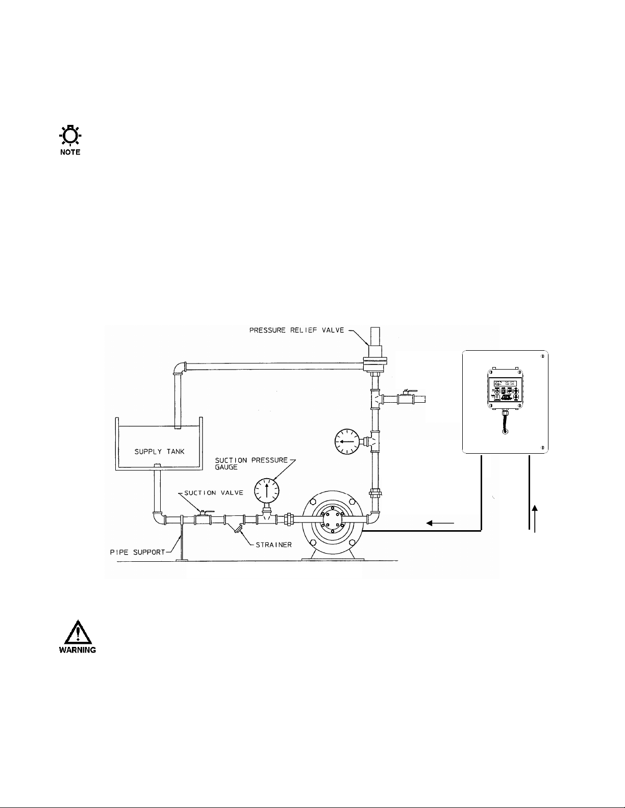
The MPC VECTOR controller must be secured to an appropriate support before use. Use appropriate
hardware to secure the MPC VECTOR controller and pump to a smooth vertical surface. No assembly is
required for the MPC VECTOR controller itself.
AC TO MOTOR
AC POWER IN
Figure 1 – Typical Installation.
A
VOID LOCATIONS WHERE THE
HEAT [LESS THAN
F
AHRENHEIT)] OR DIRECT SUNLIGHT. FAILURE TO OBSERVE THIS WARNING COULD DAMAGE THE
MPC VECTOR
0°°°° C
ELSIUS
AND VOID ITS WARRANTY
MPC VECTOR
(32°°°° F
AHRENHEIT) OR GREATER THAN 40
.
WOULD BE SUBJECTED TO EXTREME COLD OR
°°°° C
ELSIUS
(104 °°°°
5
Page 12

5.2 Installation Notes
The MPC VECTOR is a microprocessor-based controller that uses electro-static sensitive CMOS
components. Do not make any (high or low voltage) electrical connections without adequately grounding
the MPC VECTOR and the worker to eliminate an electro-static charge between the two. A conductive
wrist strap worn by the worker and attached to the MPC VECTOR’s internal ground plate is
adequate to satisfy this requirement.
Calibration is an important element of successful MPC VECTOR operation. If a flow meter is being used for
process feedback the flow meter must be calibrated prior to MPC VECTOR calibration according to
manufacturer recommendations.
Conduit connections can carry fluids and vapors into the MPC VECTOR causing damage and void the
warranty. Care should be taken when installing conduit to protect against fluid/vapor entry. If necessary,
provide sealed entries or conduit drains near the point of entry. The user must supply the correct connection
for the power entry, as per the local codes and requirements. Any cable entrances that are not used should
be appropriately sealed against moisture and vapors.
5.3 Electrical Wiring
Wait a minimum of 5 minutes after disconnecting power before servicing the MPC VECTOR or
pump motor. Capacitors retain a charge even after power is removed from the controller.
1. Make the motor connections between the control unit and the pump motor (ref. Figure 3).
2. Make the incoming AC power connections and the outgoing power connections to the pump motor (ref.
Section 5.3.2). These will allow you to operate the MPC VECTOR and attached Eclipse pump.
3. Decide which signal (control) Inputs and Outputs (e.g., 4-20mA in) will be used and make those
connections (ref. Section 5.3.4).
4. Power-up and test the MPC VECTOR to confirm the connections and check for proper operation.
5. Configure the software via the menu system for the desired operational conditions. Depending on the
anticipated function, users may need to enter settings for the following:
a. Analog input signal, so the MPC VECTOR can accept a process input signal
b. Digital input settings, for example start/stop and/or tank level inputs
c. Digital output settings, for example auto/manual status and/or alarm outputs
6. Conduct a final power-up and test the MPC VECTOR to confirm the connections and check for proper
operation.
7. Go to the Section 6 – Start Up and Operation for details on how to perform the power-up tests.
5.3.1 Controller Layout
The design of the MPC VECTOR incorporates all control circuitry onto one easily accessed circuit board.
This board is located on the inside of the main controller. Gain access to this board by removing the 2
cover screws allowing the cover to hinge open.
6
Page 13
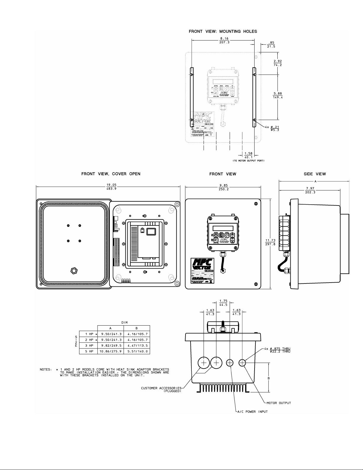
Figure 2 – Controller Layout and Dimensions
7
Page 14

5.3.2 Power Wiring Information
• Verify the correct supply voltage (230VAC single-phase or three-phase) with the nameplate
affixed to your MPC VECTOR. Ensure that your supply voltage matches the MPC VECTOR
configuration.
• The 1 hp, 2 hp, and 3 hp AC drives use single phase or three phase 230VAC input. The 5 hp
AC drive must be powered by three phase 230VAC input only.
• Wires should be routed within the enclosure in a manner that maintains separation between
high voltage and low voltage conductors. High voltage conductors should be routed to the side
opposite the control circuitry.
• Incoming power wiring should adhere to all applicable local and national electrical codes and
regulations. A circuit breaker or fuse must be provided as noted below.
• Upon initial application of AC power, a current inrush will occur to charge the DC bus
capacitors. This is normal operation, and breakers and other circuit protection devices should
be sized accordingly.
The MPC VECTOR requires one connection to an external power source. It uses this same
connection to power its own supply as well as the AC pump motor. You must take all of these loads
into consideration when sizing the branch circuit (see Table 1). A circuit breaker or disconnect
switch with fuses must be wired in series with terminals L1 and L2/N in accordance with all
applicable local and national electrical codes and regulations. The circuit breaker or disconnect
switch shall be located in close proximity to the MPC VECTOR controller installation, and must be
marked or labeled to identify it as the power disconnect for the MPC VECTOR.
Recommended Minimum Wiring and Circuit Breaker
Power
Requirements
MPC VECTOR
and 1.0 Hp motor
MPC VECTOR
and 2.0 Hp motor
MPC VECTOR
and 3.0 Hp motor
MPC VECTOR
and 5.0 Hp motor
Actual
10.6 A 15 A 14 AWG 2.0 mm2 5.8 A 10 A 14 AWG 2.0 mm
14.8 A 20 A 14 AWG 2.0 mm2 9.1 A 15 A 14 AWG 2.0 mm
19.7 A 25 A 12 AWG 3.5 mm2 12.4 A 20 A 14 AWG 2.0 mm
Single Phase 208/230 VAC Three Phase 208/230 VAC
Circuit
Draw
--- --- --- --- 19.6 A 25 A 12 AWG 3.5 mm2
Breaker
Wire
Size
Wire
Size
Actual
Draw
Circuit
Breaker
Wire
Size
Wire
Size
2
2
2
Table 1 – Sizing Branch Circuits
The MPC VECTOR controller is provided with a 7/8” thru hole for incoming AC power wiring and
a 7/8” thru hole for motor wiring at the bottom of the enclosure. Utilize the appropriate conduit
fittings to route and seal the supply wires into the MPC VECTOR enclosure.
The power wires are secured to the terminal strip at the bottom end of the AC drive as per Table 2.
Remove approximately 0.20 – 0.25” of insulation from the end of each conductor. Loosen the
terminal strip screw, and insert the stripped wire end fully into the terminal. Tighten the screw to
8
Page 15
secure the conductor, making certain that the terminal grips the wire, not the insulation. Ensure that
all wiring meets applicable local and national codes and requirements.
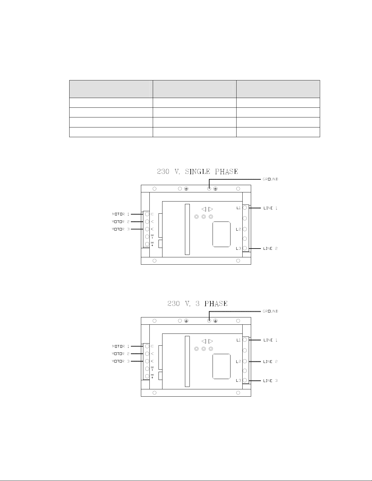
5.3.3 Power Wiring Diagram
MPC VECTOR Drive
Terminal
L1 Line 1 Line 1
L2 N/C Line 2
L3 Line 2 Line 3
Ground Plate Ground Ground
Single Phase 208/230 VAC Three Phase 208/230 VAC
Table 2 – AC Drive Terminals
Figure 3 – AC Power Connections
Wait a minimum of 5 minutes after disconnecting power before servicing the MPC VECTOR or pump motor.
Capacitors retain a charge even after power is removed from the controller.
9
Page 16
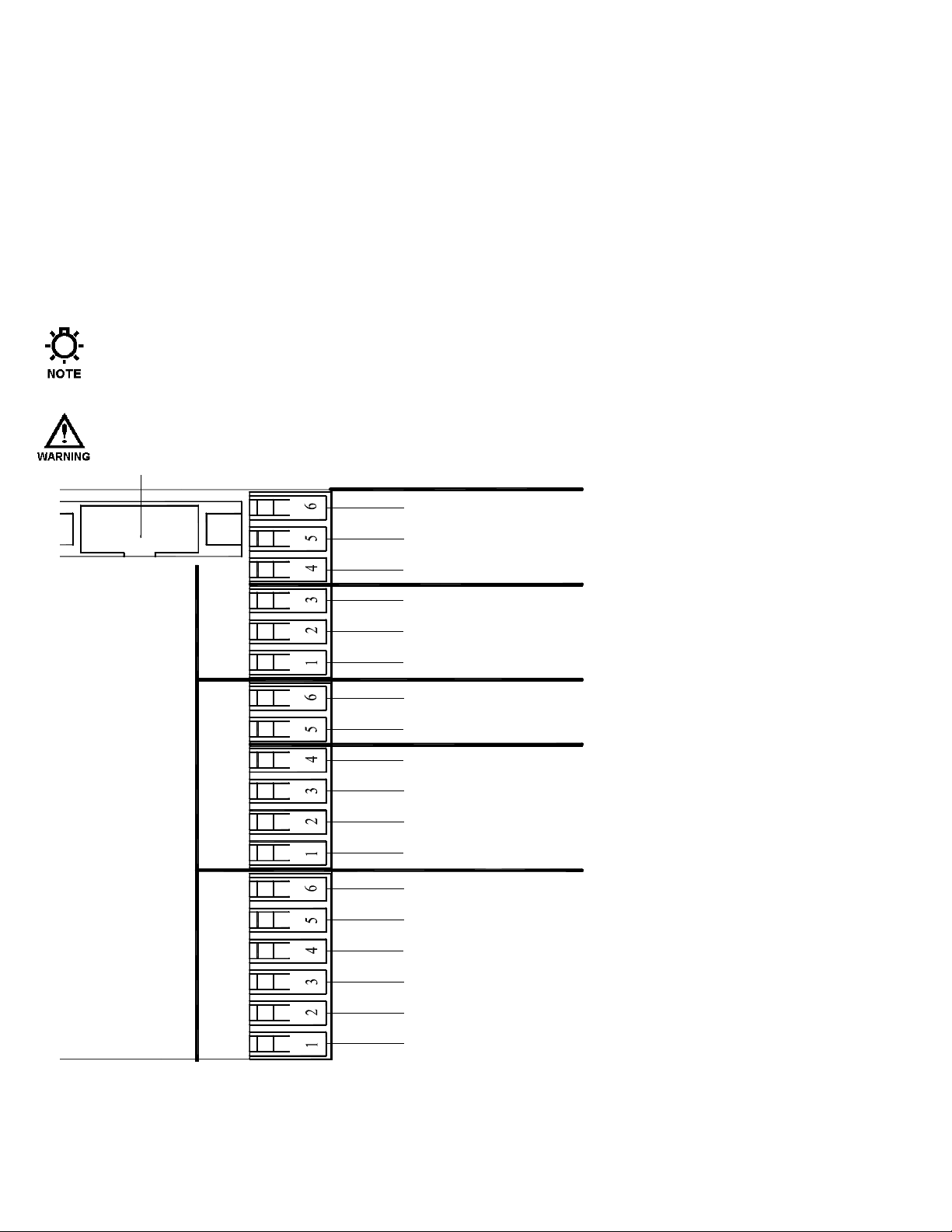
5.3.4 Input/Output Signal Wiring
4-20 INPUT
(
)
(
)
Signal wiring is routed through the two unused conduit openings at the base of the MPC VECTOR.
All input/output signals are connected to the terminal strips at the edge of the MPC VECTOR circuit
board except for flow meter feedback which is connected to a separate terminal block. Use caution
to observe proper wire location and signal polarity. Always cap or plug unused openings. Wires
should be routed with in the enclosure in a manner that maintains separation between high voltage
and low voltage conductors. Ensure all low voltage wiring is installed as per any applicable local
and national electrical codes and regulations.
Utilize 16 to 22 AWG, 250 V shielded cable with a 75o C insulation rating (or better) for all signal
input and output wiring. Recommended strip length is 0.39” or 10 mm. Refer to Figure 4 below for
signal connection locations.
Unused conduit openings should be plugged as required to avoid ingress of moisture and contaminants
into the MPC VECTOR enclosure. Do not remove the factory provided plug from openings that are not
required for field wiring.
I
T IS RECOMMENDED THAT A WRIST STRAP BE WORN WHEN MAKING CONNECTIONS TO ANY PRINTED
CIRCUIT BOARD
.
GROUND
J20
J11
J23
J14
ANALOG IN 2
ANALOG IN 1
F L O W M E T E R S I G N A L
P R O C E S S S I G N A L
DIGITAL INPUT
GROUND
DIGITAL IN 2
DIGITAL IN 1
4-20 OUTPUT
ANALOG OUT 1
GROUND
DIGITAL OUTPUT
GROUND
DIGITAL OUT 3
DIGITAL OUT 2
DIGITAL OUT 1
REMOTE
BLACK/WHITE
WHITE
SHIELD
BLACK/GREEN -GREEN
Figure 4a – Signal Connections
10
BLACK/RED
RED
Page 17
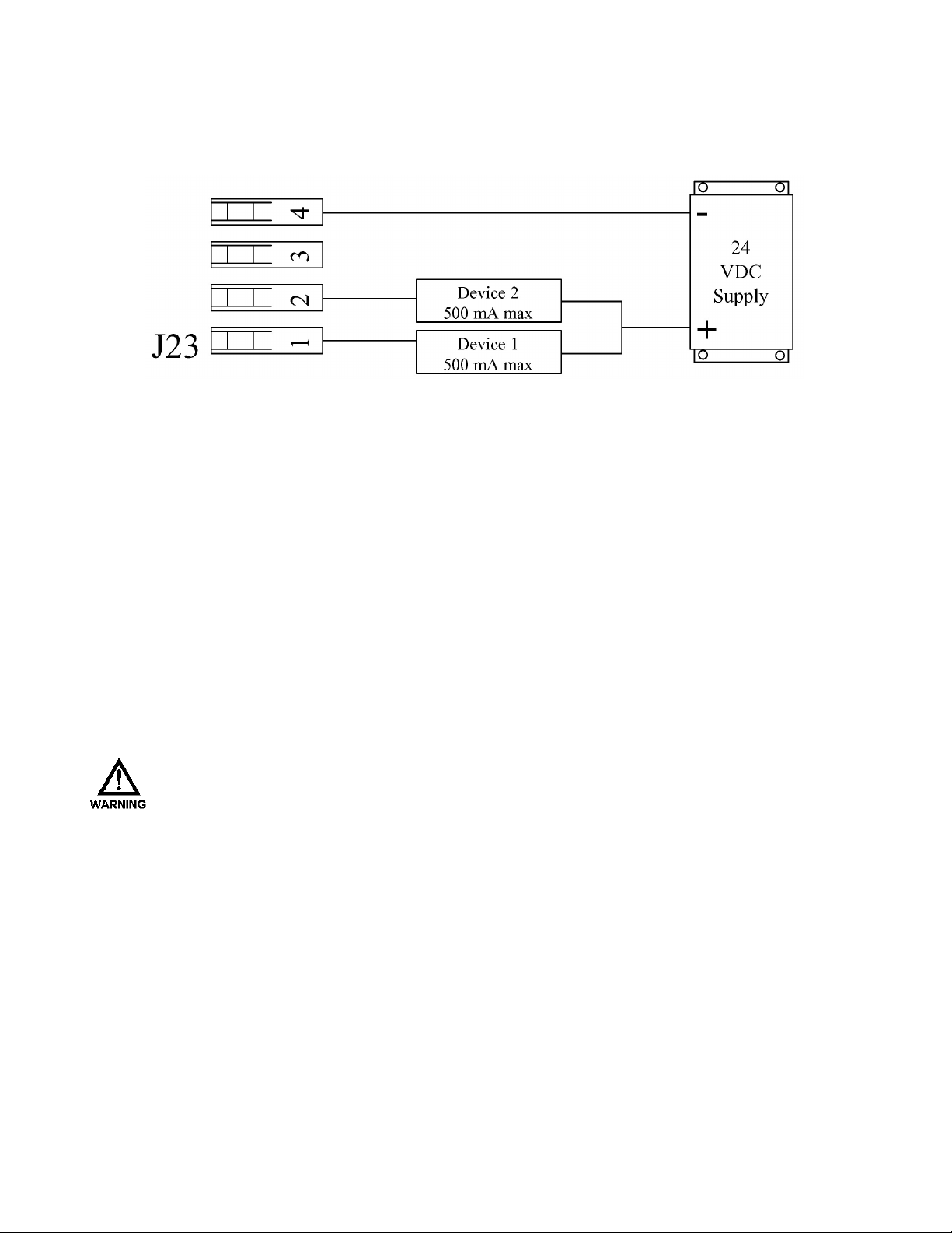
Digital output signals can drive devices such as relays or indicator lamps. 5 to 24 VDC power must be
supplied from an external source. Each output has a maximum current capability of 500 mA. Maximum
voltage capability of these circuits is 40 VDC (see Section 12, Specifications, for more information).
Figure 4b – Sample Digital Output Connections, (power can be in the range of 5 – 24 VDC)
5.4 Check Wiring and Close Access Cover
Double-check all of your electrical connections. Pay attention to polarity of all inputs and outputs – both
low and high voltage. Additionally, insure that all terminals are clamping onto the bare conductor, not on
its insulation. Ensure that wires will not be trapped or pinched when front cover is replaced and secured.
Ensure that excess insulation is not removed from the wires, as this can lead to poor connections or faulty
operation.
Replace the main access cover and secure the 2 screws.
5.5 Confirm Correct Incoming Power
W
ITHOUT PRIOR OPERATING KNOWLEDGE, IT IS IMPOSSIBLE TO TELL IF THE PUMP MOTOR WILL
RUN WHEN POWER IS APPLIED TO THE
NECESSARY STEPS TO ENSURE THAT ALL ASPECTS OF SAFETY HAVE BEEN CONSIDERED (E.G.,
ELECTRICAL, HYDRAULIC, ETC
.).
Turn on power at the mains or distribution panel. If the MPC VECTOR's incoming power is connected
correctly, the backlighting on the MPC VECTOR’s display will illuminate (depending on lighting
conditions, it may be necessary to shade the display to confirm illumination). If the display is not
illuminated, first check the line voltage with a voltmeter. If the voltage is not correct, return to Section
5.3.2 – Power Wiring Information. Otherwise, proceed with the next step.
MPC VECTOR. Y
OU ARE RESPONSIBLE FOR TAKING THE
11
Page 18

6. Start Up and Operation
6.1 Overview
Once all electrical connections have been made, your MPC VECTOR is ready for setup and operation. The
following sections detail the procedures required to complete the MPC VECTOR start up.
W
HEN POWER IS SUPPLIED TO THE UNIT, LINE VOLTAGE IS PRESENT WITHIN THE
ENCLOSURE EVEN WHEN THE MOTOR IS
DURING START-UP, IT IS NECESSARY TO RUN THE PUMP MOTOR. THIS WILL CAUSE FLUID TO
DISCHARGE FROM THE PUMP. YOU ARE RESPONSIBLE FOR SAFELY DIVERTING FLOW FROM THE
PUMP DURING START-UP AND CALIBRATION
6.2 Critical Parameters
For proper operation of the MPC VECTOR control, at startup the following parameters and calibrations must
be entered and/or verified:
Parameter(s) Reference IOM Section
OFF.
MPC VECTOR
.
Pump maximum flow Section 6.6
Flow meter calibration (if using this feature) Ref flowmeter IOM as required
Flow calibration in speed mode Section 8.2
Motor calibration for Vector mode Section 10
4-20 mA analog signal calibration Section 8.3
Flow meter type setup Section 9
12
Page 19
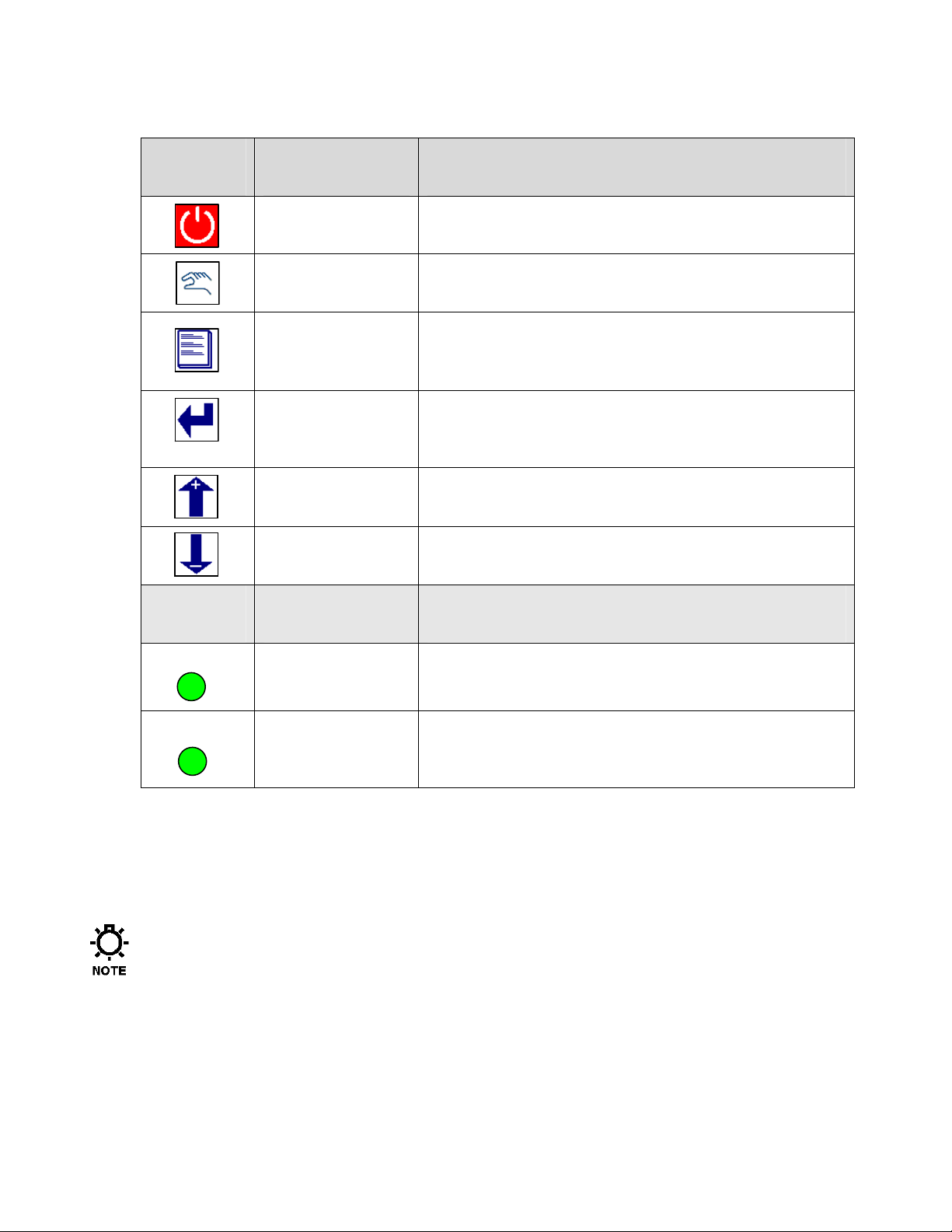
6.3 Keypad/Lamp Operation
Green = Manual Control Off = Automatic Control
MANUAL
ON
Key Function Description
Motor On/Off Press to start pump, press again to stop pump
Lamp Color Description
Auto/Manual
Menu
Enter
Arrow Up
Arrow Down
Green, Amber,
Red, Off
Press to toggle between automatic operation and manual
control of the pump
Press to adjust controller settings, to exit the menu system,
to move cursor back when entering values, or to step back to
higher level menus
Press to accept changes in menus, to move cursor forwards
when entering values, and to access lower level menus.
Press to adjust values upwards, and to scroll through menu
options
Press to adjust values downwards, and to scroll through
menu options
Off = Motor off Green = Motor on
Amber = Remote standby Red (blinking) = Error
Green, Off
Table 3 – Keypad and Lamp Operation
6.4 Confirm Display and Keypad Functionality
The example display messages are shown in English for demonstration purposes. If an alternate
language has been set, the text is displayed as a translation of the English version.
Now that you have confirmed that the MPC VECTOR is receiving power, it is necessary to confirm that the
display and keypad are functioning properly. On normal power-up, the display appears for approximately 2
seconds.
P U L S A F E E D E R INC.
F W : 0 0 . 0 0 / 0 0.00
The first four digits displayed are the software revision for the MPC VECTOR control board, and the second
four indicate the software revision for the remote board.
13
Page 20

The revision numbers should be identical for both units. Unpredictable or unstable operation may result
from mismatched software revisions.
Please note that it may be necessary to adjust the display contrast. Please refer to Section 8.6 if this is
required.
6.5 Motor Parameter Setup
The MPC VECTOR controller interfaces closely with the Eclipse pump motor. The MPC VECTOR needs to
know certain details about the motor in order to function properly. End users may have to input or adjust
motor parameters before operation. Use the following as a guide:
If you: Have received your MPC VECTOR and Eclipse pump and motor as a unit from the factory,
and Your MPC VECTOR to motor wiring distance is less than 25 feet
Then you should not have to perform any parameter setup or calibration. All parameters and setup have been
completed for you at the factory.
If you: Are using the MPC VECTOR with a motor that did not come from the factory, or
Your MPC VECTOR to motor wiring distance is greater than 25 feet, or
You are replacing the motor on an existing setup
Then you may have to enter the motor parameters, and you will have to perform a motor auto-setup
procedure. Please reference Section 10, Motor Parameter Setup and Tuning, before proceeding with
operation of your MPC VECTOR controller.
6.6 Setting Max Flow and Max Speed
What is Max Flow?
The value entered into the Max Flow is largely used for display purposes. It limits the flow rates that can be
entered during normal operations, as well as during analog calibration routines and PulsaGuard calibration.
Internally it is also used in PID calculations.
What should my Max Flow be set to?
Max Flow can vary for a gear pump based on the viscosity of the fluid being pumped and the system
pressure. It is recommended that the Max Flow be set 10% higher than your pump is rated for at 0PSI. This
will allow for a full range of data entry.
What if I try to set my pump to a flow higher than it can actually achieve for my current pressure and
viscosity?
The pump has internal software protections and validations which prevent the motor from exceeding 1800
RPM (approximate). If the pump can only achieve 2.5GPM at 1800 RPM for your system configuration and
the flow rate is set to 10GPM, the motor will spin at 1800 RPM and produce 2.5GPM.
What is Max Speed?
Max Speed is the maximum speed that the motor can spin, according to the manufacturer. This is largely
unused by the MPC Vector at the moment and will not affect operations. It is recommended that this value is
kept at 1800 RPM.
14
Page 21

Setting Max Flow
1) Begin at the main screen displaying the current flow/speed setpoint
S E T P T 0 . 0 0 G P M
F L O W 0 . 0 0 G P M
2) Press the MENU key to access the menus.
- M E N U -
C A L I B R A T I O N
3) Press the UP or DOWN arrow keys until you get to System Setup.
- M E N U -
S Y S T E M S E T U P
4) Press the ENTER key to access System Setup Menus.
S Y S T E M S E T U P
S T A T U S
5) Press the UP key until you see the Information setup option.
S Y S T E M S E T U P
I N F O R M A T I O N
6) Press the ENTER key to access the Information screens.
P U L S A F E E D E R , INC
F W : 1 . 0 4 / 1 .04
7) Press the UP or DOWN arrow keys until you see Max flow and Speed displayed.
M A X : 6 . 0 0 G P M
M A X : 1 8 0 0 R P M
8) Press the Enter key to allow Max Flow to be edited. A blinking cursor will appear
M A X : 6 . 0 0 G P M
M A X : 1 8 0 0 R P M
9) Press the UP or DOWN arrow keys to manipulate the flow rate until you reach your max flow.
M A X : 8 . 5 0 G P M
M A X : 1 8 0 0 R P M
10) Press the ENTER key to accept the new Max Flow rate. Note that the blinking cursor has moved to the
Max Speed location.
M A X : 8 . 5 0 G P M
M A X : 1 8 0 0 R P M
11) Press the ENTER key again to save the Max Flow and Max Speed. Note that the blinking cursor
should disappear at this point.
M A X : 8 . 5 0 G P M
M A X : 1 8 0 0 R P M
15
Page 22

6.7 Flow Display
The MPC VECTOR will display calibrated pump flow in GPH, LPH, GPM, or LPM on the digital display
when configured for flow control. The motor speed (in RPM) may also be viewed while in flow control.
Changes to the flow units are made in the System Setup Menu.
6.8 Wrapping up
Your MPC VECTOR is now commissioned for use. Note that you cannot configure the software in a way
that would damage the MPC VECTOR. Typically, whenever you are about to set a critical value (e.g.,
Calibrate Flow), you are always prompted to confirm your change before it takes effect. If you are ever
dissatisfied with the configuration of your MPC VECTOR, you can always return to the Factory Defaults by
referring to Section 6.7.
16
Page 23

6.9 Factory Re-Initialization
Factory Re-initialization is typically not required. When re-initializing your MPC VECTOR, all of the
system settings and calibration information will be overwritten by the original factory default settings.
The controller must be re-configured and re-calibrated to your specifications.
A Factory Re-initialization should be performed only if there is reason to believe that the MPC VECTOR is
operating abnormally. The condition usually manifests itself with inconsistent or erratic operation – often
associated with meaningless characters on the display, or exaggerated numerical values. Commonly, a user
has entered incorrect parameters, or made changes to the setup of the control.
Once a re-initialization has been performed, all operating parameters should be checked and adjusted or reentered as necessary, including maximum flow and rpm, motor parameters, flow and analog signal
calibrations, etc.
Factory Re-Initialization:
1. Press the MENU key to access the System Setup Menu
- M E N U -
C A L I B R A T I O N
2. Press the UP arrow key to display
- M E N U -
S Y S T E M S E T U P
3. Press the ENTER key
S Y S T E M S E T U P
S T A T U S
4. Press the UP arrow key twice
S Y S T E M S E T U P
F A C T O R Y I N I T
5. Press the ENTER key
P R E S S E N T E R
T O F A C T O R Y INIT
6. Press the ENTER key
A R E Y O U S U R E?
Y E S = E N T E R NO=ME N U
7. Pres the ENTER key
R E S E T T I N G P UMP
T O F A C T O R Y INIT
17
Page 24

7. Input/Output Setup
Use the “DIGITAL I/O” and “ANALOG I/O” menus to activate the functions required for the intended
application.
Users may also reference Section 14 – Menu Maps for additional configuration assistance
7.1 Analog Input Setup
Two Analog Inputs are provided for the User. Analog Input 1 is used for Setpoint input. Analog Input 2 is
used for systems configured for analog process feedback from a flow meter.
7.1.1 Analog Input 1 – Setpoint
See Figure 4 – Signal Connections to insure that you have your Analog Input signal connected to the proper
location before activating. Use the “ANALOG I/O” menu to activate the analog input signal function. The
menu can be used to set the analog input to either ACTIVE or INACTIVE. The setpoint input should be
calibrated prior to activation (ref. Section 8.2 – Analog Input Calibration).
7.1.2 Analog Input 2 – Flowmeter Feedback
See Section 9 Flow Meter Input for installation instructions. The flow meter input signal must be configured
properly prior to use. Use the “FLOW SENSOR” sub-menu under “SYSTEM SETUP” to enable the process
feedback analog input. The flow sensor type must be set to “ANALOG” to enable this input. The process
feedback input should be calibrated prior to activation (ref. Section 8.1 – Pump Flow Calibration).
7.2 Digital Input Setup
7.2.1 Multi-purpose Digital Inputs
Each of the 2 Digital INPUTS can be selected as: Inactive
Each can be set as normally OPEN or normally CLOSED. For example, if an input is set to ON/OFF and
NORMALLY CLOSED, this means a CLOSED switch will activate the pump. A NORMALLY OPEN
setup will give the opposite response. These inputs are to be attached to a dry contact circuit only, apply no
voltage to these inputs.
Tank Level Input
Leak Detection (using external device)
Remote ON/OFF Input
Flow verification Input
18
Page 25

7.3 Analog Output Setup
No setup is required for the analog output. Analog output is always available at the corresponding terminals
(see wiring diagram Figure 4a, Section 5.3.4). The analog output follows and is proportional to motor speed.
7.4 Digital Output Setup
Each of the 3 Digital OUTPUTS can be selected as: ON/OFF Status
AUTO/MAN Status
Leak Detected
Alarm Indicator
Tank Level Status
Each can be set as normally OPEN or normally CLOSED. For example, if an output is set to ON/OFF
INDICATION and NORMALLY CLOSED, this means that when the motor is running (indicator lamp is
ON) the output will be CLOSED. A NORMALLY OPEN setup will give the opposite response.
Digital output circuits are transistor based and limited to 40 VDC maximum, see Section 5.3.4, Input/Output
Signal Wiring, and Section 11, Specifications, for more information).
19
Page 26

8. Calibrations
As a convention in this manual:
“WET” calibrations
pump running with fluid, or an electrical signal input provided at the appropriate terminals.
will refer to those that require normal operating conditions, for example the
“DRY” calibration
or that a specific input signal be present.
Some of the calibration routines may be performed either way. Note any system requirements listed
for each routine.
routines are run under other conditions, and often do not require the pump to run
8.1 Pump Flow Calibration
Pump flow calibration is not necessary for the standard speed controller. It is only necessary for models
configured for flow meter feedback. The selected flow meter should meet or exceed requirements listed in
the Flow Meters section (ref. Section12 - Specifications). The flow meter should also be calibrated prior to
MPC VECTOR calibration according to manufacturer specifications.
Y
OUR
MPC VECTOR
DEPENDENT AND FLOW METER DEPENDENT. YOU MUST ALWAYS PERFORM A CALIBRATION WITH
THE
MPC VECTOR
CALIBRATE THE UNIT MAY RESULT IN DAMAGE TO SYSTEM COMPONENTS
The pump may be calibrated in WET (under normal operating conditions) or DRY (performed with pump
off) conditions.
8.1.1 WET Flow Calibration
The Wet Flow Calibration routine will require that the user turns on the pump. The flow meter should be
configured and calibrated prior to MPC VECTOR calibration (refer to flow meter IOM for calibration
instructions). Please note that it must be safe to run the pump and dispense liquid into the system in order to
complete this calibration. The pump should be fully primed with the product in order to complete an
accurate calibration.
IS NOT FACTORY CALIBRATED AS THE CALIBRATIONS ARE SYSTEM
INSTALLED IN YOUR SYSTEM PRIOR TO USE. FAILURE TO PROPERLY
.
1. Press the MENU key to access the Calibration Menu.
2. Press the ENTER key to access Pump Flow Calibration screen.
3. Press the ENTER key to access Wet Pump Flow Calibration screen.
4. Press the ENTER key to begin Flow Calibration
R P M 0
20
- M E N U -
C A L I B R A T I O N
C A L I B R A T I O N
P U M P F L O W
P U M P F L O W
W E T C A L
C A L S P E E D
Page 27

5. Using the UP and/or DOWN arrow keys adjust the motor speed to approximate setpoint. This speed is just
a reference point for the MPC MPC VECTOR to measure flow meter input. If the maximum motor speed
for a given application is known, it is best to use this as a flow calibration point.
C A L S P E E D
R P M 1800
6. Press the ENTER key to accept the calibration speed.
S T A R T M O T O R
Y E S = E N T R N O =MENU
7. Press the ENTER key to start the motor and advance to the flow entry screen. You cannot start the motor
with the motor key during MENU operations.
P U M P F L O W
F L O W : 0 0 0 . 00GPM
T
HE MOTOR WILL START WHEN THE ENTER KEY IS PRESSED. MAKE SURE THAT YOUR SYSTEM IS
PREPARED FOR OPERATIONS BEFORE STARTING THE MOTOR
8. Obtain flow rate from flow meter.
.
Pay close attention to the units used for flow rates. The flow rate entered into the MPC VECTOR
calibration MUST match the units displayed on the MPC VECTOR. You may back out of this
calibration routine at this time and change the MPC VECTOR flow units, if necessary.
9. Enter the flow rate from your flow meter. If flow meter output is not visually available you may obtain
flow rate through measurements and stopwatch. The UP and DOWN arrow keys may be used to change
each digit. Press the ENTER key after each digit has been entered to advance to the next digit or the
MENU key to back up.
P U M P F L O W
F L O W : 0 0 4 . 80gpm
The calibration routine may be exited at any time prior to pressing ENTER after the last digit has been
entered by pressing the MENU key (several times) to back out. If there is a problem with flow units or
flow meter calibration back out before completing MPC VECTOR calibration and fix the problem.
10. Once all digits have been entered and the ENTER key is pressed, the WET flow calibration routine is
complete and you should see the following screen.
P U M P F L O W
C A L I B R A T E D
After the ENTER key has been pressed it will take several seconds for the calibration routine to
complete.
11. Pump flow calibration is complete.
12. Press the MENU key three times to exit back to the main operating screen.
21
Page 28

8.1.2 DRY Flow Calibration
The DRY Flow Calibration routine does not require the pump to run. Instead, the user may input known
flow meter feedback values. This process can be used for fine adjustment of flow rate display, or in
situations where it is not possible or not safe to run the pump during calibration.
The DRY Flow Calibration Routine may be used to make small adjustments to the MPC VECTOR
calibration to ensure to make the MPC VECTOR display more closely matches the Flow Meter display.
If you are not using a flow meter for feedback, the DRY flow calibration routine can be used, but will
display motor RPM instead of mA value during the procedure.
1. Press the MENU key to access the Calibration Menu.
- M E N U -
C A L I B R A T I O N
2. Press the ENTER key to access Pump Flow Calibration screen.
C A L I B R A T I O N
P U M P F L O W
3. Press the ENTER key to access Wet Pump Flow Calibration screen.
P U M P F L O W
W E T C A L
4. Press the UP or DOWN key to access DRY Pump Flow Calibration screen.
P U M P F L O W
D R Y C A L
5. Press the ENTER key to access the DRY Pump Flow Calibration routine. A blinking cursor will show you
that you are adjusting the Current (mA).
M I N S E T P T 0.0MA
F L O W : 0 . 00GPM
6. Press the UP and/or DOWN keys to adjust the Current setpoint.
M I N S E T P T 4.0MA
F L O W : 0 . 00GPM
7. Press the ENTER key to accept this setpoint. The Cursor will now blink on the second line, indicating that
the Flow is the active field. Press the UP and/or DOWN keys to adjust the Flow setpoint.
M I N S E T P T 4.0MA
F L O W : 0 . 00GPM
8. Press the ENTER key to access the MAX setpoint values. The cursor will blink on the top line indicating
that the Current setpoint may be adjusted.
M A X S E T P T 1 6.0MA
F L O W : 4 . 00GPM
22
Page 29

9. Press the UP and/or DOWN arrow keys to adjust the Max Current setpoint.
M A X S E T P T 2 0.0MA
F L O W : 4 . 00GPM
10. Press ENTER to accept the Current Setpoint. The cursor will blink on the bottom line indicating that the
Flow setpoint may be adjusted.
11. Press the UP and/or DOWN arrow keys to adjust the Max Flow setpoint. Note that you can not set this
value greater than the Maximum Flow the pump is rated for (you may see the maximum rated flow in the
Pump Information screens).
M A X S E T P T 2 0.0MA
F L O W : 5 . 92GPM
You may back out of the DRY calibration routine at any point up to now without saving any calibration
settings. Use the MENU button to back up.
12. Press the ENTER key to save the new Analog Calibration values. Upon completion of Calibration
you should see the following screen.
P U M P F L O W
C A L I B R A T E D
13. Press the MENU key several times to return to Operations Mode.
To optimize feedback, it is best to set 4mA to 0 flow and 20mA to a value slightly higher (10-20% or
so) than your max desired flow setting. This allows the user a full range of flow setpoints as well as
giving the MPC VECTOR the best possible Analog resolution.
23
Page 30

8.2 Analog Input Calibration
If you are not using the 4-20mA input to the MPC VECTOR for control, skip this section. To calibrate the
Input Current you must first correctly wire an external signal source. Refer to Section 5 – Installation: Low
Voltage Input Connections, Analog Input. As with the flow calibration routine, the Analog Input may be
calibrated WET or DRY. To perform a WET calibration, the signal-generating device must be active and
capable of generating the full range (low to high) of potential input signals. A DRY calibration requires no
input signal.
If the MPC VECTOR is configured for Speed Control instead of Flow Control the displays below reflecting
pump flow will be replaced with pump speed displays. For example the bottom line of step 8 of the WET
Calibration routine will display ‘SPEED XXXX RPM’.
8.2.1 “WET” Analog Input Calibration
1. The starting display will be:
S E T P T X X . X X X
F L O W X X . X X X
2. Press the MENU key
- M E N U -
C A L I B R A T I O N
3. Press the ENTER key
C A L I B R A T I O N
P U M P F L O W
4. Press the UP arrow key twice, to access the analog input calibration
C A L I B R A T I O N
A N A L O G I N P U T
5. Press the ENTER key
A N A L O G I N P U T
(with a field signal)
6. Press the ENTER key
A P P L Y M I N M A
E N T E R T O S T ART
7. Apply your desired minimum mA control signal to the MPC VECTOR (usually 4 mA)
8. Press the ENTER key
M I N S E T P T 4 . 2 M A
F L O W 0 .00GP M
(The mA value will be equal to your input signal level)
(The lower line shows the setting the MPC VECTOR will use for this signal value)
9. Press the UP and DOWN arrow keys to change the Speed/Flow corresponding to the Analog Input Value.
24
W E T C A L
Page 31

10. Press the ENTER key once more to accept the calibration value
A P P L Y M A X M A
E N T E R T O S T ART
11. Apply your desired maximum mA control signal to the MPC VECTOR (usually 20 mA)
12. Press the ENTER key
M A X S E T P T 2 0 . 2 M A
F L O W 7 .01GP M
(The mA value will be equal to your input signal level)
(The lower line shows the setting the MPC VECTOR will use for this signal value)
13. Press the UP and DOWN arrows to adjust the Speed/Flow corresponding to the Analog Input value.
14. Press the ENTER key once more to accept the calibration value
A N A L O G I N P U T
C A L I B R A T E D
15. Analog input signal calibration is complete
16. Press the MENU key three times to exit back to the main operating screen.
If you receive the following message:
C U R R E N T D E L TA
O U T O F R A N G E
This indicates that there is not a wide enough range between your maximum and minimum analog signals.
The minimum signal range is 3 mA. The most likely source of this error is the user did not change the value
of the incoming analog signal when moving from the MIN calibration to the MAX calibration.
The analog input signal calibration procedure should be performed again, ensuring that a minimum
of 3 mA difference exsists between the MIN and MAX signal levels.
25
Page 32

8.2.2 “DRY” Analog Input Calibration
1. The starting display will be:
(keypad only, no signal present)
S E T P T X X . X X X
F L O W X X . X X X
2. Press the MENU key
- M E N U -
C A L I B R A T I O N
3. Press the ENTER key
C A L I B R A T I O N
P U M P F L O W
4. Press the UP arrow key twice, to access the analog input calibration
C A L I B R A T I O N
A N A L O G I N P U T
5. Press the ENTER key
A N A L O G I N P U T
W E T C A L
6. Press the UP or DOWN key
A N A L O G I N P U T
D R Y C A L
7. Press the ENTER key to access the DRY Pump Flow Calibration routine for ANALOG Flow Meters. A
blinking cursor will show you that you are adjusting the Current (mA).
M I N S E T P T 0.0MA
F L O W : 0 . 00GPM
8. Press the UP and/or DOWN keys to adjust the Current setpoint.
M I N S E T P T 4.0MA
F L O W : 0 . 00GPM
9. Press the ENTER key to accept this setpoint. The Cursor will now blink on the second line, indicating that
the 4mA Flow is the active field. Press the UP and/or DOWN keys to adjust the Flow setpoint.
M I N S E T P T 4.0MA
F L O W : 0 . 00GPM
10. Press the ENTER key to access the MAX setpoint values. The cursor will blink on the top line indicating
that the Current setpoint may be adjusted.
M A X S E T P T 1 6.0MA
F L O W : 4 . 00GPM
26
Page 33

11. Press the UP and/or DOWN arrow keys to adjust the Max Current setpoint.
M A X S E T P T 2 0.0MA
F L O W : 4 . 00GPM
12. Press ENTER to accept the Current Setpoint. The cursor will blink on the bottom line indicating that the
Flow setpoint may be adjusted.
13. Press the UP and/or DOWN arrow keys to adjust the Max Flow setpoint.
M A X S E T P T 2 0.0MA
F L O W : 5 . 92GPM
You may back out of the DRY calibration routine at any point up to now without saving any calibration
settings by pressing the MENU key several times.
1. Press the ENTER key to save the new Analog Calibration values. Upon completion of
Calibration you should see the following screen.
A N A L O G I N P U T
C A L I B R A T E D
2. Press the MENU key several times to return to Operations Mode.
27
Page 34

8.3 Analog Output Calibration
The analog output calibration routine maps the motor speed of the MPC VECTOR to a 4-20mA output signal. The
output signal is NOT proportional to pump flow. If a 4-20mA signal representing flow is required it must be
obtained by splitting the flow meter output signal.
1. The starting display will be:
S E T P T X X . X X X
F L O W X X . X X X
2. Press the MENU key
- M E N U -
C A L I B R A T I O N
3. Press the ENTER key
C A L I B R A T I O N
P U M P F L O W
4. Press the UP ARROW key to access the analog output calibration
C A L I B R A T E D
A N A L O G O U T P UT
5. Press the ENTER key
S E T 0 % S P E E D TO
0 4 . 0 M A
6. Use the UP and DOWN arrow keys to adjust the output signal as required. The actual output signal
will vary and can be monitored with a meter or your facility control system. The value displayed on
the screen may not match the actual output signal and is for visual reference only.
7. Press the ENTER key once more to accept the calibration
S E T 1 0 0 % S P EED T O
2 0 . 0 M A
8. Use the UP and DOWN arrow keys to adjust as in step 6 above
28
Page 35

9. Press the ENTER key once more to accept the calibration value
A N A L O G O U T P UT
C A L I B R A T E D
10. Analog output signal calibration is complete
11. Press the MENU key three times to exit back to the main operating screen
If you receive the following message:
C U R R E N T D E L TA
O U T O F R A N G E
This indicates that the output current for 0% speed has been set greater than or equal to the output current
setting for 100% speed. Repeat the process and ensure that the 0% calibrated signal is set to a value lower
than the 100% calibrated signal.
29
Page 36

8.4 PulsaGuard Pump Protection
PulsaGuard is designed to turn your pump off when running in dangerous conditions. These conditions are
user configurable and can be easily modified to meet each application.
When flow meter feedback is being provided, PulsaGuard will turn off your motor if a low flow set point is
crossed for more than 10 seconds. This will protect the pump in under-loaded or overloaded conditions, which
would cause the flow to fall below the user’s acceptable limit. The MPC VECTOR will also trigger an alarm
condition if the flow set point cannot be reached for some reason. This alarm will be displayed on the MPC
MPC VECTOR display but will not shut the motor off. If the MPC VECTOR is operating without flow meter
feedback PulsaGuard can read the motor current and shut off the pump if the current drops below the shut off
level and stays under that level for 10 seconds, effectively protecting equipment from under-loaded conditions.
The PulsaGuard pump protection may be enabled and disabled as desired from the System Setup menus (see
section 8.4.2: PulsaGuard Enable/Disable). Note that once a calibration is performed the pump protection is
automatically enabled, you will not have to manually enable it.
8.4.1 PulsaGuard Calibrations, using Flow Meter Feedback
1. The starting display will be:
S E T P T X X . X X X
F L O W X X . X X X
2. Press the MENU key
- M E N U -
C A L I B R A T I O N
3. Press the ENTER key
C A L I B R A T I O N
P U M P F L O W
4. Press the UP key
C A L I B R A T I O N
P U L S A G U A R D
5. Press the ENTER key
M I N S E T P O I N T
S E T P T : 0 . 00GPM
6. Using the UP and DOWN arrow keys set the low flow setpoint
M I N S E T P O I N T
S E T P T : 0 . 50GPM
30
Page 37

7. Press the ENTER key to complete the PulsaGuard Calibration.
P U L S A G U A R D
C A L I B R A T E D
8.4.2 PulsaGuard Calibrations, no Flow Meter Feedback
PulsaGuard may be calibrated WET or DRY. A WET calibration requires that the user simulate
underloaded conditions.
Follow Steps 1-4 above. You should see the following screen
C A L I B R A T I O N
P U L S A G U A R D
5. Press the ENTER key.
P U L S A G U A R D
W E T C A L
WET CALIBRATION:
6. Press the ENTER key again to access the WET calibration routine.
S T A R T M O T O R
Y E S = E N T R N O =MENU
7. Run the pump to meet desired low setpoint conditions. You may adjust the speed of the motor using
the UP and DOWN arrow keys. The output current of the motor will be displayed on the screen. The
values below are not indicative of what your display will show.
M I N S E T P T 2.0A
S P E E D : 1 2 00RPM
8. Once the MPC MPC VECTOR has reached the desired low current setpoint, press the ENTER key.
P U L S A G U A R D
C A L I B R A T E D
9. PulsaGuard Pump Protection is now calibrated and enabled.
DRY CALIBRATION:
6. Press the UP key
P U L S A G U A R D
D R Y C A L
31
Page 38

7. Press the ENTER key
M I N S E T P O I N T
S E T P T : 0.0A
8. Use the UP and DOWN keys to adjust the current setpoint
M I N S E T P O I N T
S E T P T : 2.0A
9. Press the ENTER key to accept the calibration value.
P U L S A G U A R D
C A L I B R A T E D
10. PulsaGuard Pump Protection is now calibrated and enabled.
8.5 Display Contrast Adjustment
Should adjustment of the contrast level of the display become necessary, use the following procedure while
in the normal operating mode.
To increase contrast, press and hold at the same time.
To decrease contrast, press and hold at the same time.
32
Page 39

8.6 Tuning the Control Algorithm
This option should only be used by control systems engineers who are familiar with tuning PID loops.
This is not intended for the casual user. Changing these values may result in the system oscillating
without settling on the set point or never reaching the set point at all. See Section 21, Appendix 2 for
more information and theory on PID control.
The MPC VECTOR allows users to tune the motor control algorithm to speed up or slow down the MPC
VECTOR response time. This is done by adjusting the PID Controller parameter coefficients.
The user may adjust the Proportional coefficient, kp, the Integration coefficient, ki, and the Derivative
coefficient, kd, independently. The user may also view and modify the sampling period of the control loop, ts.
Modifying the PID coefficients
1. The starting display will be:
S E T P T X X . X X X
F L O W X X . X X X
2. Press the MENU key
3. Press the UP arrow key
4. Press the ENTER key
5. Press the DOWN
6. Press the ENTER key
- M E N U -
C A L I B R A T I O N
- M E N U -
S Y S T E M S E T U P
S Y S T E M S E T U P
S T A T U S
S Y S T E M S E T U P
P I D P A R A M E T ERS
P I D P A R A M E T ERS
C O E F F I C I E N T S
7. Press the ENTER key
P R O P O R T I O N A L
X . X X X
33
Page 40

8. Press the UP and/or DOWN keys to adjust the denominator, kp'
P R O P O R T I O N A L
X . 1 0 0
9. Press the ENTER key
I N T E G R A L
X . X X X
10. Press the UP and/or DOWN keys to adjust the denominator, ki'
I N T E G R A L
X . 0 5 0
11. Press the ENTER key
D E R I V A T I V E
X . X X X
12. Press the UP and/or DOWN keys to adjust the denominator, kd'
D E R I V A T I V E
X . 0 5 0
13. You may back out without saving the new PID coefficients at this point by hitting the MENU key
several times to return to the first screen. If you want to save the changes press the ENTER key
P I D P A R A M E T ERS
C O E F F I C I E N T S
14. The new PID coefficients have been set.
34
Page 41

Modifying the Sampling Interval, when Flow Meter feedback is used
1. The starting display will be:
S E T P T X X . X X X
F L O W X X . X X X
2. Press the MENU key
- M E N U -
C A L I B R A T I O N
3. Press the UP arrow key
- M E N U -
S Y S T E M S E T U P
4. Press the ENTER key
S Y S T E M S E T U P
S T A T U S
5. Press the DOWN key until you get to the PID screen
S Y S T E M S E T U P
P I D P A R A M E T ERS
6. Press the ENTER key
P I D P A R A M E T ERS
C O E F F I C I E N T S
7. Press the UP arrow key
P I D P A R A M E T ERS
S A M P L I N G P E RIOD
8. Press the ENTER key
S A M P L I N G P E RIOD
P E R I O D : XXXMS
9. Press the UP and/or DOWN arrows to adjust the sampling period, ts
S A M P L I N G P E RIOD
P E R I O D : XXXMS
10. Press the ENTER key to accept the new sampling period
P I D P A R A M E T ERS
S A M P L I N G P E RIOD
11. The new PID sampling period has been set.
35
Page 42

9. Flow Meter Input
The MPC VECTOR accepts flow meter process feedback from an analog (4-20mA) flow metering device. The
manufacturer of the flow meter is not important but the process signal must conform to a set of minimum
specifications in order to work with the MPC VECTOR.
9.1 Flow Meter Installation
Prior to installation make sure your flow meter conforms to the MPC VECTOR’s flow meter specifications
(refer to Section 13, Specifications). Your flow meter must also be calibrated independently prior to
installation.
Figure 5 – Flow Meter Connection
1. Remove MPC VECTOR power and wait 30 seconds for complete power dissipation.
2. Connect your flow meter input to the Flow Meter Input Terminal Block (ref Fig. X.XX).
3.
Plug in MPC VECTOR. After the system information is displayed the starting display will be:
S E T P T X X . X X X
F L O W X X . X X X
4. Press the MENU key
- M E N U -
C A L I B R A T I O N
5. Press the UP arrow key
- M E N U -
S Y S T E M S E T U P
36
Page 43

6. Press the ENTER key
S Y S T E M S E T U P
S T A T U S
7. Press the DOWN key five (5) times
S Y S T E M S E T U P
F L O W S E N S O R
8. Press the ENTER key to enter the Flow Sensor setup menus.
F L O W S E N S O R
S E N S O R T Y P E
9.
Press the ENTER key to see the current sensor configuration
.
S E N S O R T Y P E
I N A C T I V E
10. Press the ENTER key to change the sensor type.
S E N S O R T Y P E
< I N A C T I V E >
11. Press the UP arrow key until the analog flow meter option is displayed.
S E N S O R T Y P E
< A N A L O G >
12. Press the ENTER key to accept the new configuration.
S E N S O R T Y P E
A N A L O G
13. Press the MENU key several times to return to the Main screen.
14. Perform either a WET or DRY Flow Calibration on your MPC VECTOR (see Section 8.1: Pump Flow
Calibration).
15.
Your MPC MPC VECTOR is now ready for use with your flow meter.
37
Page 44

10. Motor Parameter Setup and Tuning
The MPC VECTOR controller must know several motor characteristics before the motor can be calibrated.
This calibration allows the controller to maintain precise control over the operation of the motor.
If the drive has not been calibrated an error will appear on the screen. In addition, at startup the User Interface
will be redirected to the Calibration/Motor Parameter sub-menu.
If your MPC VECTOR unit has been shipped from the factory as a complete unit with Eclipse pump
and motor, these parameters will have been entered at the factory. No further user input will be
required.
Note that the ranges listed in the table below reflect absolute min/max accepted by the drive and may not
match a specific application. These do not have to be set in any particular order but will be presented
sequentially by the User Interface. The parameters will need to be entered in the field if the MPC VECTOR
controller was shipped without a motor, or if the motor is changed to a different model than was originally
supplied.
S
ETTING THESE PARAMETERS IMPROPERLY AND RUNNING THE AUTO-CALIBRATION ROUTINE CAN
RESULT IN DRIVE ERRORS.
Reference motor parameter table, next page
38
Page 45

Param.
85 Motor Rated Speed Nameplate RPM Rating 300 – 65,000
86 Motor Rated Amps Nameplate FLA Rating 0.0 – 480 Amps Various 1
87 Motor Rated Volts Nameplate Voltage Rating 0 – 600 Volts 230 VAC
88 Motor Base Frequency Nameplate Frequency 25 – 500 Hz 50 or 60 Hz
91 Motor Cosine Phi Nameplate Cosine Phi 0.4 – 0.99 Approx 0.8 2
81 Invoking this parameter begins the auto-calibration routine
NOTES:
1. FLA = Full Load Amps
2. The Cosine Phi is also known as the Power Factor, this will sometimes be on the nameplate as
“PF”. If the Power Factor is given as a %, always use the decimal equivalent (for example a power
factor of 84% would be entered as 0.84) If the Cosine Phi is not provided by the motor manufacturer,
one of the following formulas may be used.
Name Description Range Typical Note
1800 RPM
RPM
COS
)2(
COS
1
−
=Φ
sincos)1(
CurrentgMagnetizin
CurrentMotor
=Φ
746
×
HPMotor
CurrentMotorVoltageMotorEfficiencyMotor
×××
732.1
After all of the Parameters have been entered, the drive needs to perform an auto-calibration routine
(Parameter 81). This calibration routine will take several seconds to complete. The user may use the Menu
Key to back up and/or out of the calibration any time prior to the auto calibration. The motor, and therefore
the pump, will not run during this auto-calibration procedure.
39
Page 46

Setup Process
1. Navigate to the
display will be:
2. Press the ENTER key
3. Use UP and DOWN arrows to adjust value as required, then press the ENTER key
4. Use UP and DOWN arrows to adjust value as required, then press the ENTER key
5. Use UP and DOWN arrows to adjust value as required, then press the ENTER key
CALIBRATION
C A L I B R A T I O N
M O T O R P A R A M
menu, and scroll to the
8 5
< 1 8 0 0 >
8 6
< 1 . 2 >
8 7
< 2 3 0 >
8 8
< 6 0 >
MOTOR PARAM
option. The starting
6. Use UP and DOWN arrows to adjust value as required, then press the ENTER key
9 1
< 0 . 8 0 >
7. Use UP and DOWN arrows to adjust value as required, then press the ENTER key
8 1
E N T E R T O S T ART
8. Press the ENTER key
C A L I B R A T I N G
9. The last screen will show
M O T O R P A R A M
c a l i b r a t e d
10. Upon completion of the routine, remove power from the MPC VECTOR controller for one minute,
and then re-apply power to complete the process.
After all of the Parameters have been entered, the drive needs to perform an auto-calibration routine
(Parameter 81). This calibration routine will take several seconds to complete. The user may use the Menu
Key to back up and/or out of the calibration any time prior to the auto calibration. The motor, and therefore
the pump, will not run during this auto-calibration procedure.
40
Page 47

11. Alarm and Error Messages
If a fatal error has occurred while in Operational Mode, the error will flash on the screen and the Red LED
lamp will also flash. The menus can still be accessed by pressing the menu key. This allows the user to try
and fix the source of the error if possible.
11.1 Error Log
As each error occurs an entry is saved in an Error Log. You may view the four most recent errors as well as the
current status through the System Setup Menus.
11.1.1 Viewing the Error Log
1. The starting display will be:
S E T P T X X . X X X
F L O W X X . X X X
2. Press the MENU key
- M E N U -
C A L I B R A T I O N
3. Press the UP arrow key
- M E N U -
S Y S T E M S E T U P
4. Press the ENTER key
S Y S T E M S E T U P
S T A T U S
5. Press the ENTER key again to view the current status
- - N O - -
- - E R R O R - -
6. Press the DOWN key to view the most recent system error
A L A R M
L E A K D E T E C T
7. Continue pressing the DOWN key to scroll through the 4 most recent errors.
8. Press the MENU key at any time, while viewing either current status or Log entries, to exit the Error
Log.
Once you see ‘NO ERROR’ in the Error Log (the screens AFTER current status) there will be no errors
in any of the subsequent positions. If the pump turns off for any reason check the Error Log to see any
messages that were reported. Some errors may clear themselves from the screen, but the entry will still
be in the Error Log.
41
Page 48

11.1.2 Clearing Error Log Entries
Any of the entries in the Error Log may be cleared while viewing by pressing the ENTER key. If the problem
is recurring or still present it may not be clearable.
11.2 Error Messages
The following table gives an example of these messages and when you can expect them to be displayed.
Message Displayed When:
FATAL ERRORS: The pump and controller will not run while one of these error conditions
exists. The Red LED will blink and the error message will flash on the screen. Users can access
the menu system by pressing the MENU key. The red LED and the message will cease when the
error condition has been corrected.
Ana lo g In pu t #X
Out o f Ra ng e
The analog input is less than 2.4 mA or greater than 24 mA
ALA RM
LOW L EV EL
The level monitoring input has triggered
ALA RM
AC DR IV E FA UL T
Internal fault
ALA RM
MOT OR E RR OR
COM MU NI CA TI ON
ERR OR
The MPC VECTOR has detected that the motor shaft is not
rotating at the expected speed
Communication error exists between the MPC VECTOR
controller and the keypad/display module
Continues next page…
42
Page 49

NON-FATAL ERRORS: The pump and controller can still be run while these conditions exist.
The Red LED will flash and the error will flash on the screen. The Red LED and error message
will cease once the error condition has been corrected.
SOF TW AR E Fa ul t
Err or = # ## #
Har dw ar e fa ul t
Err or = # ## #
Software related problem, record error number and consult
factory
Hardware related problem, record error number and consult
factory
CON SU LT f ac to ry
Err or = # ## #
Unidentified error, record error number and consult factory
USER NOTIFICATIONS: These are errors in setup or calibration. They will display on the
screen for several seconds. They can be corrected by properly completing the procedure
involved.
Can no t ac ce ss
Wit h mo to r on
Cur re nt d el ta
Out o f ra ng e
No re mo te
Con tr ol
.
User is trying to change a setting that cannot be changed
while the pump is running
Not enough difference between high and low signals during
an analog input signal calibration (min 3 mA)
User is trying to activate the AUTO mode, but there is no
remote input (mA signal or remote on/off) to the controller
For unlisted or numbered error codes, consult the factory for assistance.
43
Page 50

12. Specifications
Operation mode: AC motor speed control with sensorless speed feedback
Flow control with Flow Meter feedback
Recommended Minimum Wiring and Circuit Breaker
Power
Requirements
MPC VECTOR
and 1.0 Hp motor
MPC VECTOR
and 2.0 Hp motor
MPC VECTOR
and 3.0 Hp motor
MPC VECTOR
and 5.0 Hp motor
Actual
10.6 A 15 A 14 AWG 2.0 mm2 5.8 A 10 A 14 AWG 2.0 mm
14.8 A 20 A 14 AWG 2.0 mm2 9.1 A 15 A 14 AWG 2.0 mm
19.7 A 25 A 12 AWG 3.5 mm2 12.4 A 20 A 14 AWG 2.0 mm
Single Phase 208/230 VAC Three Phase 208/230 VAC
Circuit
Draw
--- --- --- --- 19.6 A 25 A 12 AWG 3.5 mm2
Breaker
Wire
Size
Wire
Size
Actual
Draw
Circuit
Breaker
Wire
Size
NOTE: AC drive capacitors will cause in-rush current demand when power is first applied to the unit.
Control Inputs
Analog In #1
Analog Flow Meter
Input
Flow Meter Terminal
Wiring Specification / Description
J11 pins 4-6 4-20mA control signal
Max current 30mA; Input resistance 200 Ohm
Internally protected with resetable fuse
Minimum signal accepted = 2.4 mA
Maximum signal accepted = 24 mA
4-20mA flow meter feedback signal
Block Pins 1,2,4
Max current 30mA; Input resistance 200 Ohm
Internally protected with resetable fuse
Minimum signal accepted = 2.4 mA
Maximum signal accepted = 24 mA
Wire
Size
2
2
2
Digital In #1
Digital In #2
* Digital input functions:
J11 pins 1-3 User to provide dry-contact input *
J11 pins 2-3 User to provide dry-contact input *
1. Remote on/off control of pump
2. Level input from supply tank
3. Leak Detection with external device
4. Flow detection with external device
44
Do not apply power, maximum 2K Ohm resistance to register as
“active”
Page 51

Control Outputs
Analog Out #1
Digital Out #1
Digital Out #2
Digital Out #3
* Digital output functions:
Calibration: Controller includes an on board program for signal and flow calibration.
Input Voltage: 230 (208 – 240 acceptable range) VAC
Note: factory configured only for correct input voltage range (specified at time of purchase)
Wiring Specification / Description
J23 pins 5-6 4-20mA output for pump flow indication
Max voltage out 12 Volts; Max current out 30mA;
Max load resistance 300 Ohm
Internally protected with resetable fuse
J23 pins 1-4 Transistor-based output, various functions *
J23 pins 2-4 Transistor-based output, various functions *
J23 pins 3-4 Transistor-based output, various functions *
1. Triggering an external relay due to a fault condition
2. Auto/Manual status
3. On/Off status
4. Leak Detected
5. Tank level status indication
Single Phase or Three-Phase (Single-Phase not available for 5 hp)
50 or 60 Hz.
All digital outputs maximum 40 VDC, maximum 500 mA
NOTE: requires external power source
Tolerance: Input voltage +/- 10% maximum
Input frequency range 48 Hz to 62 Hz
Motor Req: Commercially available motor supplied by the manufacturer of the pump controller
See following page for further motor information
Motor Distance: Maximum motor to controller distance is 100 feet (30.5 meters)
For distances greater than 25 feet (7.6 meters) see motor information, next page
Consult factory for distances greater than 100 feet (30.5 meters)
Keypad: Mounted to MPC VECTOR main enclosure, can be made remote from the enclosure
Display: Backlit 2 line extended temperature 16 character LCD
Enclosure: NEMA 4X and IP56 ratings
Altitude: 3300 Ft (1000 M) above sea level (derate 5% for each additional 3300 feet)
Humidity: 0-90% (non-condensing)
Temperature: 0o C (32o F) Minimum operating temperature
40o C (104o F) Maximum operating temperature
Earth Leakage
Current: Size Earth Leakage Circuit Breakers (ELCB) to a detection level of 30 mA or greater
45
Page 52

Motor Selection and Requirements
General Specifications
All motors used with the MPC VECTOR controller must meet these minimum specifications:
• 230 VAC, 50 or 60 Hz 3-phase input power AC induction motor
• 1800 rpm (60 Hz) or 1500 rpm (50 Hz) synchronous speed
• Service Factor 1.05 or greater
• Class F Insulation (minimum)
• Refer to your equipment specifications and documentation for the correct frame size
• Motors may or may not need feet and/or a C-face mount depending on equipment
Turndown Requirements
Motor turndown ratings are dependent on the application and intended use of the pump. Users should understand and
take into account the following factors when considering motor selection:
• Application required turndown ratio
• Viscosity of pumped liquid
• Length of wiring between the MPC VECTOR controller and the pump (motor)
Application Required Turndown Range
Liquid Viscosity
Low, below 50 CPS 3:1 or 4:1 N/A
High, above 50 CPS 3:1 or 4:1 10:1 Consult factory
NOTE: when pumping liquids with low viscosity, pump performance is greatly diminished at slow rotational speeds due
to internal slip. Therefore, high speed turndown ratios are not expected in this type of application.
Cable Length Minimum Required Motor Turndown Rating
MPC VECTOR to motor less than 25
feet (7.6 meters)
MPC VECTOR to motor greater
than 25 feet (7.6 meters)
4:1 10:1 20:1
(see note below)
Use ratings guidelines in chart above
4:1 or 10:1 turndown 20:1 turndown
Must use 10:1 inverter duty
rated motor
Consult factory
Consult factory
NOTE: the maximum pump to controller distance is 100 feet (30.5 meters). If longer distances are required, please
contact the factory. Line and load reactors can be utilized to allow operation over longer distances.
46
Page 53

13. Model Identification
Position Sample Specifies Options
1 and 2 EP
3 C
4 B
5 X
Enclosure Type
Motor Hp Rating
Language
EP – MPC VECTOR
C – meets NEMA 4X specifications
*
A - Fractional to 1.0 Hp (.37 kW); Drive Input: 208-230 Volt
B - 2 Hp (1.5 kW); Drive Input: 208-230 Volt
C - 3 Hp (2.2 kW); Drive Input: 208-230 Volt
D - 5 Hp (3.7 kW); Drive Input: 208-230 Volt (3-phase only)
X – English (default)
A - German
B - French
C - Spanish
* Reference specific motor selection requirements in Section 12, Specifications
47
Page 54

14. Menu Maps
48
Page 55

49
Page 56

50
Page 57

15. Factory Default Values
Parameter Factory Set Value
Digital Input #1 INACTIVE, normally closed
Digital Input #2 INACTIVE, normally closed
Analog Input #1 INACTIVE
Analog Input #2 INACTIVE
Digital Output #1 ON/OFF indication, normally closed
Digital Output #2 AUTO/MANUAL Indication, normally closed
Digital Output #3 ALARM Indication, normally closed
Security Code Default = 0000
Language ENGLISH
MODE Local (Manual)
UNITS GPM (gallons per minute)
16. Retrieval of Setup Information
Users can access the
this may be helpful in troubleshooting:
Controller software revisions
Pump serial number
MPC VECTOR model number
Pump maximum flow and PulsaGuard minimum flow setpoint
Pump maximum speed and PulsaGuard minimum current setpoint
system SETUP : INFORMATION
17. Special Key Press Access
In This SCREEN Press MENU and ENTER at the same time to:
MEN U
ANA LO G I/ O
MEN U
DIG IT AL I /O
Press the MENU key to exit from any of these special screens.
Show calibration and RAW data for analog inputs
Feature not available
menu, which will list the following data,
51
Page 58

18. Troubleshooting Guide
Problem Potential Cause Solution
DISPLAY
No Display No power supplied. Check power source. plug & circuit breaker
Back-lighting Supply power wired incorrectly. Check wiring.
Supply power outside of specification. Check voltage/frequency against specification.
Contrast out of adjustment. Adjust as per section 8.4 No Text on
Display
No power No power supplied. Check power source. Plug & Circuit Breaker
Indicators Supply power wired incorrectly. Check wiring.
Supply power outside of specification. Check voltage/frequency against specification.
Software did not initiate properly. Remove and re-apply AC power
POWER
52
Page 59

19. Spare Parts
User replaceable parts for the MPC VECTOR.
Pulsafeeder P/N Description
NP530091-000 ½” wiring liquidtight connector
NP530137-000 ¼” wiring liquidtight connector
W213946-NTR Hand-held enclosure gasket
NP550113-000 Membrane keypad for hand-held
W772568-STL ½” conduit opening plug
W772585-018 ¼” conduit opening plug
53
Page 60

20. Appendix 1, Handheld Wiring
The hand-held controller for your MPC can be placed as far as 1000 feet from the main control unit. It is
recommended that all calibrations be completed before the cable is lengthened, as these tasks are easier when
the pump and hand-held controller are close to each other.
POWER TO THE UNIT MUST BE OFF!
SHOULD BE WORN WHEN MAKING CONNECTIONS TO ANY
The following standard length cables are available from Pulsafeeder for use with the MPC:
Cable Length Part Number Notes
6 feet NP530130-000 Standard, supplied with all MPC controllers
Others per foot NP530147-000 (1 ft) NOTE: do not exceed 1,000 feet total length
20.1 Removal and Connection of the Cable from the Handheld:
A GROUNDING WRIST STRAP
PCB
1. Open the handheld unit by removing the 4 screws on the face of the unit.
2. Open the unit by separating the cover from the base.
3. Use care with the keypad tail that is connected to the board, it can be left in place during this process.
4. Make a note of what color lead is in each position of the terminal block “J5”. Cut the tie-wrap that
secures the cable. Unscrew each screw on the terminal block “J5” and remove each lead.
5. Loosen the outer domed nut on the liquid tight, releasing the tension on the cable. Pull the cable
through the liquid tight. Thread the new cable through the liquid tight with enough length to reconnect
to the terminal block.
6. Cut the shield wire as close as possible to the outer insulation at the remote end only.
7. Wrap the end of the cable with electrical tape to insulate any remaining shield so that it will not
contact the circuit board, equipment case, or any other parts.
8. Referring to the notes taken earlier, connect each lead of the new cable to the proper position of the
terminal block, lock the lever back in place to hold lead. NOTE: It is recommended that you insert and
secure one lead at a time.
9. Tighten the dome nut of the liquid tight to secure/seal cable.
10. Check that the keypad tail is still firmly connected, re-insert if necessary.
11. Replace cover and tighten screws. Be sure the o-ring is in its groove, paying special attention to the
corners. NOTE: Do not over tighten.
54
Page 61

20.2 Removal and Connection of the Cable from the Base Unit:
Wait a minimum of 5 minutes after disconnecting power before servicing the MPC or pump motor. Capacitors
retain a charge even after power is removed from the controller.
1. Remove the screws that are securing the cover of the main unit.
2. CAUTION: The cover is wired and should be opened gently being sure not to pull any of the wires
that are connected to it.
3. Make a note of what color lead is in each position of the terminal block “J14”. Unscrew each screw on
the terminal block “J14” and remove each lead.
4. Loosen the outer domed nut on the liquid tight, releasing the tension on the cable. Pull the cable
through the liquid tight. Thread the new cable through the liquid tight with enough length to reconnect
to the terminal block.
5. Prepare the end of the cable as per figure 7 on the following page. Ensure that the shield is fully
insulated until the point where it enters the terminal. No part of the shield should be allowed to come
in contact with the circuit board, equipment case, or any other surface.
6. Note that the black-green lead should be paired with the green wire.
7. Referring to the notes taken earlier, connect each lead of the new cable to the proper position of the
terminal block, and then lock the lever back in place to hold lead. NOTE: It is recommended that you
insert and secure one lead at a time.
8. Tighten the dome nut of the liquid tight to secure/seal cable.
9. Replace cover carefully being sure not to crimp any of the cables/leads between cover and enclosure
and tighten screws.
10. Power the unit on, if all connections were properly made the unit will power as normal and the display
will show the start up screen.
55
Page 62

REMOTE
TAPE SHIELD
MIS-WIRING OF J5
MAY DAMAGE UNIT.
AC
J20
DRIVE
J11
J23
J14
AN00446-002
BLACK/WHITE
WHITE
SHIELD
BLACK/GREEN - GREEN
BLACK/RED
RED
RED
BLACK/RED
GREEN
BLACK/GREEN
WHITE
BLACK/WHITE
Figure 6 – Handheld Remote Wiring
Figure 7 – Wire Preparation Detail, Base Unit End
56
TAPE END
Page 63

Figure 8 – Handheld Remote
57
Page 64

21. Appendix 2, PID Theory and Adjustment
The PID control method allows the MPC Vector to accurately maintain a specific desired setpoint for flow rate
from the pump it is connected to.
The PID Control Loop is a widely accepted general purpose control algorithm which is built into the MPC
Vector. A PID control loop consists of three components which each have their own specific responsibilities in
the control loop; the Proportional, Integral, and Derivative components. Although these mathematical terms
are derived from calculus, and are internally implemented as such, the PID can be tuned without using a
calculator by simply understanding the roles each of the three components play. Note that if you aren’t
interested in a semi-technical discussion of PID Control Loops you can skip ahead to Section 21.3.
21.1 PID Controller Theory:
The basic PID Control Loop consists of an input command, the control system, and feedback (see diagram,
following page). The user enters an input flow rate. This command is sent through the control system which
decides what the new motor speed should be. That motor speed command is sent to the pump which then
changes the output rate. A flow meter at the output of the pump measures the output flow and feeds the data
back to the controller. Based on the feed back the control system adjusts the motor speed and subsequently the
flow in an attempt to meet the required set point. This process is repeated continuously bringing the flow rate
closer and closer to the target until it eventually settles on the target. In the drawing, both the Requested Flow
Rate and Control System are integrated into the MPC Vector controller.
58
Page 65

Basic MPC Vector Control Loop
Flow Rate
Flow
1 2 3 5
4
1
Flow output from flow meter
2
3
4
5
Requested
PID Control
System
Pulsafeeder
Pump
Flow
Meter
Output
Requested flow rate from the user
Motor speed command from the control system
Flow output from the pump
Flow measurement from the flow meter
The function we are controlling is liquid flow from the pump, and the variable being controlled by the MPC
Vector is motor speed. This control must be based on some type of feedback, in this case a flow meter
measuring liquid flow rate.
Feedback and Error
Feedback is critical in control systems. The feedback lets the controller know the actual flow rate being output
by the pump at all times. Utilizing the feedback, the control system is able to determine the error which can be
defined as the difference between the expected flow rate and the actual flow rate. The PID controller acts on
the error, manipulating the process variable being controlled (in the case of the MPC Vector, motor speed) in
order to bring the process closer to the setpoint, thereby eliminating the error.
The PID controller does not act on the actual flow rate being reported by the flow meter, it acts on the error
between the actual flow rate, and the desired setpoint, it’s goal being to eliminate the error between the two as
much as possible.
Sampling Rate
In the digital world the control loop is run at some base period which is called the sampling rate, Ts. After the
initial command is given the control system waits for this period of time and then samples the output,
compares it to the set point, and makes motor speed adjustments. After the same period of time expires again,
it samples the flow rate again and compares it to the expected flow rate and adjusts. This continues as long as
the pump is running. Like many other options for the MPC Vector, this is a configurable setting. The sampling
rate of the MPC Vector should be at least twice as fast as the sampling rate of the flow sensor.
59
Page 66

21.2 Three Control Components:
The PID controller has three adjustable internal components, all of which contribute to the final output value,
they are proportional, integral, and derivative.
Proportional Component
The proportional component of the control system (also known as “gain”) is concerned with the current error
(“current” as in time, not electricity). The component is calculated by multiplying the current error by a
proportional coefficient, commonly known as Kp or proportional gain. Since the proportional component is
only concerned with current error it is able to contribute to initial startup speeds. Think of the proportional
gain as the component which gives a jump start to the pump. Typical values of Kp for this application are in
the 0.25 -> 0.7 range.
Proportional Part = Kp * error
Integral Component
The integral component of the control system (also known as “reset”) provides a historical memory to the
system. This is accomplished by adding the errors into an error summation. The sum of the errors is then
multiplied by an integral coefficient, Ki which is also called the integral gain. Because the integral component
is a historical component, it can take some time to build “history”. The Integral component is used mainly to
force the control to track closer to the desired setpoint, to eliminate any “offset”. Typical values of Ki are in
the same range as Kp, 0.25 -> 0.7.
Integral Part = Ki * error sum
Derivative Component
The derivative component (also known as “rate”) provides a predictive element to the system. The derivative
component compares the current error and previous error to calculate the approximate change over the last
sample period. This is then multiplied by the differential coefficient, Kd which is also called the differential
gain. When the flow rate of the pump is rising, the differential component is used to keep it from rising too
fast. This is because as you get closer to the flow setpoint, the current error will be smaller than the last error.
The differential term can be used to stabilize systems with excessive overshoot, it slows down the response as
the setpoint is reached.
Derivative Part = Kd * (error – last error)
60
Page 67

21.3 PID Basic Summary, what happens when I…
When the proportional control is increased:
Initial rise time to setpoint gets faster
Overshoot once setpoint is reached tends to increase (gets worse)
Steady-state error can be reduced but will never be eliminated
Settling time (ability to hold setpoint) is not strongly affected
Proportional is used mainly to affect the initial startup of the system, how quickly it reaches the desired
setpoint. Too much proportional control will result in overshoot and oscillation, and inability to hold a
setpoint over time.
When the integral control is increased:
Initial rise time to setpoint gets faster
Overshoot once setpoint is reached tends to increase (gets worse)
Steady state error is eliminated with the proper setting
Settling time (ability to hold setpoint) is increased (gets worse)
Transient response ( for example to an upset condition) may get worse
Integral is used mainly to tune the system to reach a certain setpoint, to eliminate any offset the might be
present, for example the desired flow rate is 5.0 gph, but the system settles and runs at a consistent 5.2 gph. If
too much integral control is used, the system can overshoot, not settle, and not react smoothly to transient
(temporary) upset events.
When the derivative control is increased:
Stability of the system is increased
Rise time to setpoint is not significantly affected
Overshoot is controlled and decreased with the proper setting
Settling time is decreased and controlled with the proper setting
Steady state operation is not affected significantly
Derivative is used to tune out oscillation of the system around the desired setpoint. Too much derivative
control will result in a system that never reaches setpoint, reacts too slowly, or is unstable and will not hold
setpoint.
A properly tuned PID loop will:
Reach the desired setpoint in a reasonable amount of time
Maintain operation at or very close to the setpoint with minimal oscillation
React quickly to transient changes or upset conditions
61
Page 68

21.4 Putting it all together to run the MPC Vector
The proportional, integral, and differential components are all added together into a command sum which is
used to set the motor speed. The motor speed command does have software protection which prevents the
motor speed from ever exceeding the max motor speed or from being negative and therefore if the command
loop is unstable, no damage can be caused to the drive, motor, or pump. Please be aware though that the
motor could reach maximum speed during tuning and all necessary system precautions should be taken.
Also note that the differential part alone can not be used to start the motor since it depends on previous values.
If the previous saved error matches the current error then the differential part will be 0 and therefore the
differential part alone will not start the motor reliably. It is possible to eliminate one of the parts by setting the
appropriate coefficient to 0 (i.e. if you want a PI only controller set Kd to 0 to eliminate the differential part).
However the tuning steps below assume that all 3 parts will be used.
Step 1 – Configure the MPC Vector (reference earlier sections of this IOM for more detail)
1. Make sure that the chosen flow meter is hooked up to the proper location in the MPC Vector.
2. Flow units should be set appropriately in the menu
3. Max flow should be set to at least the max flow achievable by the pump at max speed.
4. Flow sensor type should be set appropriately (digital or analog)
5. Flow calibration should be performed to make sure the MPC Vector flow reading matches flow meter
feedback.
Step 2 – Choosing the test setpoint
In order to tune the PID loop it is necessary to choose a test speed. For most purposes the test flow should be
set to approximately 80 – 85% of the max flow. If the test point is too close to the maximum flow, you may
not notice the overshoot. If the test point is too low you may have an unstable system at higher flow rates.
Step 3 – Tune the Proportional gain
1. Start with an integral gain of 0 and a derivative gain of 0. The proportional gain should be set to allow
the motor to start reliably.
2. Set the motor to the test setpoint
3. Start with a proportional gain of 0.1
4. Make sure that the integral and differential gains are 0
5. At the main operations mode screen, attempt to start the pump. If the motor starts and settles at a low
speed with minimal flow then the proportional gain is set. If not, increase the gain by 0.05 and try
again. Continue until motor start condition is met reliably.
Step 4 – Tune the Integral gain
1. The Integral gain is what will ultimately pull the speed up to the desired setpoint. Note that because
the Integral gain is based on a sum it takes some time for the Integral part to stabilize.
2. Make sure that the proportional gain is set as found above. differential gain is still 0
3. Start with an integral gain of 0.05
4. At the main operations mode screen, start the pump. You should see that the flow is now slowly
building towards the setpoint. Increasing the integral gain will cause the buildup to occur faster. Keep
adding 0.05 to the integral gain until you overshoot your setpoint. As an example, if your setpoint is 5
GPM, your gain might go to 5.1 GPM before falling down to 4.9 GPM or so and oscillate for a few
seconds.
62
Page 69

Once you see the oscillation, back the integral gain down by 0.05 – 0.1. Start the pump again and make sure
that the flow rate does not overshoot the setpoint significantly.
Note: you may want to use a stopwatch to time how long it takes to get to 80% of the setpoint, especially if you are
using the Pulsaguard pump protection. Pulsaguard will stop the pump if the minimum flow is not reached within the
timeout limit. In any case the pump should be able to get to at least 90% of the given flow setpoint within 25 seconds.
Step 5 – Tune the derivative gain
The derivative gain is not required under all circumstances. In many cases, a PI controller alone is sufficient to
control the pump flow. If derivative gain is added, start with a low setting (0.05 or so) and keep adjusting in
0.05 increments until desired settling time is met.
21.5 Troubleshooting
My flow rate is never reached. How can I fix it?
If the flow rate is never reached you have what is called an over-damped system. Try increasing the Integral
gain to help pull the setpoint up higher. Also, make sure your flow rates and units match. If you are trying to
set a flow higher than the pump can provide, you’ll never reach it!
My flow goes past the setpoint and back below again and oscillates a long time. How can I fix it?
Some oscillation is natural in many PID controlled systems. To minimize it you need to decrease the
Proportional and/or Integral gains to slow the system down a bit.
63
Page 70

BULLETIN No. IOM-MPCV-0206
Rv J
Engineered Pump Operations
2883 Brighton-Henrietta Townline Road
Rochester, New York 14623
Telephone: (585) 292-8000 Fax: (585) 424-5619
http: //www.pulsa.com pulsa@idexcorp.com
 Loading...